MORE HANDBOOKS ARE ON THEIR WAY! We will let you know when they get here.
×


Stockholm tar
-
Posts
866 -
Joined
-
Last visited
Content Type
Profiles
Forums
Gallery
Events
Everything posted by Stockholm tar
-
Hi Dirk, No problem (well not much), and it was an interesting exercise – in keeping the old brain cells working! I don't exactly see how my log will be that useful, as I'm not sure there's much I can teach you.
-
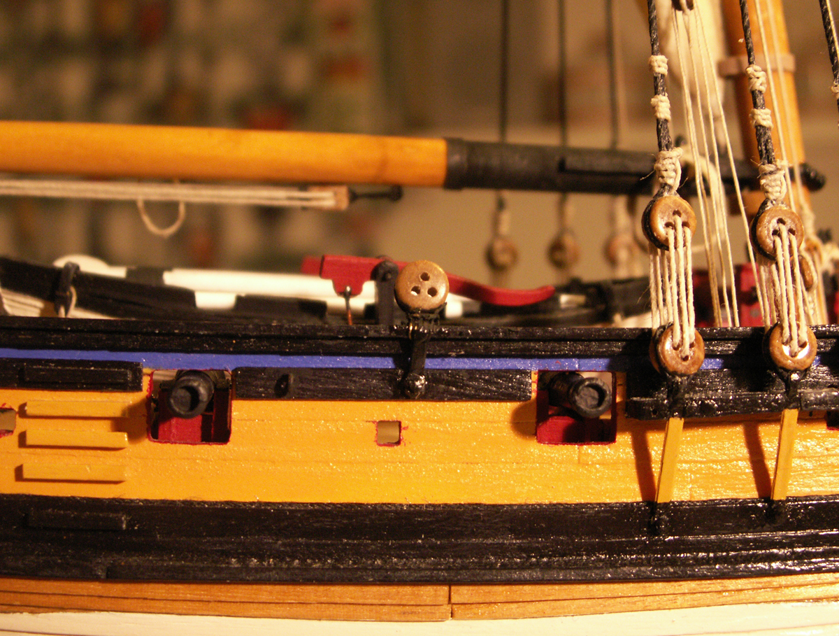
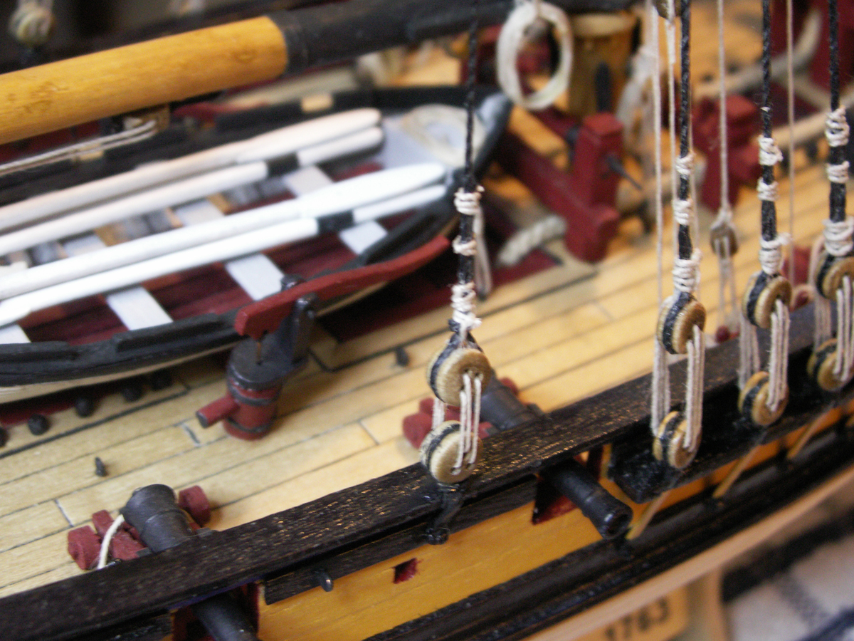
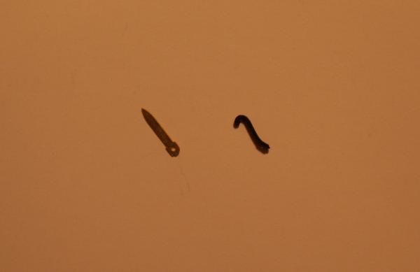
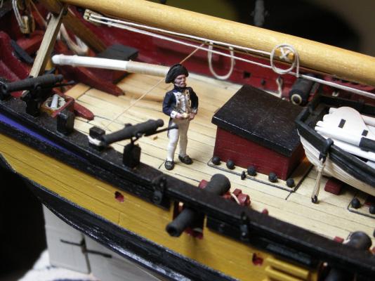
The kit is provided with two running backstays, one on each side but, in addition I decided to add two standing backstays, such as fitted to the Alert. This arrangement would appear to be the more likely – which is not really surprising, considering the large sail area of these cutters, and the mast support required. The backstays go next over the masthead after the shrouds, the standing ones nearest the mast first, followed by the running backstays further aft. The standing backstays are fitted with deadeyes and lanyards, of a similar size to those for the shrouds, and I purchased four extra 5mm deadeyes for them. I had previously set eyebolts into the side of the hull for these backstays but now realised that they would be neither sufficient nor in the right position, and so removed them. The lower deadeye of the standing backstay sits on the edge of the cap rail, being bolted to a metal strengthening strap, which effectively transmits the pull of the shroud to the hull. On considering what might I might use for these I remembered the short brass strips left over in the kit, originally intended as handles (!) for the swivel guns and which I hadn’t used, but retained amongst my spare parts. However, they looked as though they just might make passable backstay straps. (Moral: never throw anything away you think you might find a use for!) One end of each strip has a hole drilled in it, which I thought to use for pinning the strap to the side of the hull (conveniently through the holes which had previously held the eyebolts) whilst the other end comes to a point. After having rounded off the square corners at the ’hole’ end and slightly widened the hole itself (for some reason a new similar–sized pin wouldn’t fit!), I then turned the strip round and bent over the point, so that it formed a hooked shape. (My thinking was that this would hold firmly on the caprail, whilst leaving a small gap between it and the rail to pass a wire strap around the deadeye. The bent angle should also fit into the groove in the deadeye.) The finished strap was then laid aside, whilst I made a similar one for the backstay on other side. (Making up the pair together not only ensured that the same procedure was followed for both but the two will, hopefully, end up looking reasonably similar.) I had originally thought to glue the strap and its deadeye to the hull as a single unit but, in doing this, I couldn’t be sure that the angle of the deadeye to the lie of the shroud would be correct. I therefore decided it was better to fix the strap first, then mount the deadeye to it. (I also only have one pair of hands and it would have been difficult, to say the least, to manage all of these procedures at the same time!) The way I eventually decided on to attach the strap, was to first cut the retaining bolt to the right length then, holding the end with small pliers, pass it through the hole in the strip, brush the other end with CA and push it into the hole in the hull – at the same time angling the strap to the seized shrouds on the mast, using a simple ruler. (A bit heath robinson, and it had of course had to be done quickly before the glue went off, but it did work after a fashion.) A length of suitably-sized, flexible, wire was then passed under the turned over part of the strip on the rail and glued, leaving one end long, the other very short. The wire was to form the retaining strap around the deadeye. The wire was painted black, and the long end was then passed around the groove in the deadeye and under the bent over part of the strap. It was gently worked tight, with a pair of long-nosed pliers in one hand, the other aligning the deadeye in the direction of the lie of the shroud. The deadeye itself was left free within the wire strap, so that it could be correctly orientated. The long end of the wire was wound firmly three or four times around strap below the deadeye, anchoring the short end, being fixed with CA. A touch-up with black paint, and the job was done. (I may as well point out an error here, before the eagle-eyed amongst you do so, in that the deadeye is upside down! My fault entirely, being caught up in the intricacies of the work – but I am afraid the error will now have to remain.) The whole process had been a little intricate so, rather than go straight to fitting the backstay strap on the other side, I first decided to rig the backstay and lanyard on the strap that I had just finished. The backstays, both standing and running, should be of a slightly smaller size than the shrouds, and I opted to use 0.7mm thread for them. The backstays on each side are of course single, the upper end being passed around the mast and seized to itself. Apart from that the same procedure was followed as previously for the shrouds. The distance between the two standing backstay deadeyes when rigged I decided to make about about half that of the main shrouds, in order that all of the deadeyes would be more of a uniform height. Having rove the backstay lanyard in the normal way, and as earlier described for the shrouds, I left the end long whilst I made and rigged the opposite side deadeye fittings and shroud, which were done in the same way. Both backstays were then finally tensioned, each lanyard being threaded between the shroud and the top of the deadeye with a needle, before being fastened off around the shroud. Moving on to the straps for the running backstays, here again I decided that the eyebolts I had earlier placed for them would both be insufficient, and in the wrong position. I could now also see that it would be easier, with the mast and in situ, to judge where they should be positioned. Searching around for suitable material, I again remembered that left over from the swivel guns. This included the strips of metal originally intended for the gun supports, but which I didn’t think had looked quite right, and so had swopped for something else. The strips were rather long, having two creases in their length where they were supposed to be bent at right angles, giving two long sides and a middle shorter side, to form the support. I therefore cut one of the longer sides off, a process which left two holes, one in the remaining long side, and one in the short. The crease between them was slightly bent to accomodate the uneven side of the hull, and to which the long side could be glued. The hole in that side was used to pin the strap to the hull. The hole in the short end was used to attach the hooks of the running tackle, when the backstay was set up. With a pair of pliers I cut off the square corners at the short end, leaving the part with the hole proud, and which would protrude above the rail when positioned. I rounded off all the corners and then painted the finished straps black. Using a length of thread from the masthead to align the shroud straps, I then fixed all four in position with CA. New holes then had to be drilled in the hull, through those in the lower part of the straps, for the pins. This operation had to be done very carefully, first using a drill size smaller than the hole and then enlarging it, so that the movement of the drill bit didn’t knock off the strap. (This actually did happen with one of them – which, naturally, promptly ’pinged’ off onto the floor, although I did eventually find it.) This operation took a little while, but the straps were all finally glued and pinned in position. It was then just a question of tidying up the upper wale and rail, and touching up the black paint on both. The final job will be to attach the running backstays themselves and their associated tackle. However, this will have to wait until next time, as there was one small task to be done before that, and whilst I still had the access to do it. This was to position the first crew member on deck, the young lieutenant and commanding officer… Next time: Setting up the running backstays.


-
Correct hitch and advice on rigging a flag needed
Stockholm tar replied to Gabek's topic in Masting, rigging and sails
Jay, Not so much of the 'old', if you don't mind. -
Correct hitch and advice on rigging a flag needed
Stockholm tar replied to Gabek's topic in Masting, rigging and sails
Gabe, Fully understand. I'm sure we can wait. -
Tony, Thank you for those kind words. I'm not sure she's that beautiful though, and I could list a few glaring errors, I've managed to hide - but then as you said, we are our own worst critics! However, you might have a point, re. the focus. Well, I suppose there are things to be said for keeping things simple, and I've learnt to live with it (or perhaps that should be without it), but just occasionally I think it would be nice to have all this machinery. I do however, have a scroll saw at the summer cottage which comes in handy on occasion... Btw, I hope to have an update to my log soon which, I have a feeling, is somewhat overdue...
- 269 replies
-
- 2
-

-
- Caldercraft
- First build
- (and 3 more)
-
Tony, Good post on those upgrades, and I especially liked your technique for sanding the base of the gratings – so simple, and sets one to thinking now why didn't I think of that? That's why MSW is so good, someone is bound to think of new ways of doing things. I have to say that I am rather envious of yours, and others, workshops. Not having a dedicated area in our flat, I use the worktop in the kitchen for my modelling, which means that I have to clear it all away after each session. Naturally using anything other than simple tools, like a Dremel, is out as it would create too much dust, and would certainly take up too much space – plus my wife might have something to say! It's nice though to see what others are doing. I'd certainly agree with you, that thinking around the problems that crop up keeps the old brain cells functioning!
- 269 replies
-
- 1
-
-
- Caldercraft
- First build
- (and 3 more)
-
Correct hitch and advice on rigging a flag needed
Stockholm tar replied to Gabek's topic in Masting, rigging and sails
Gabe, I'm sure we're only too glad to help. Will your Swift be in the gallery? -
Correct hitch and advice on rigging a flag needed
Stockholm tar replied to Gabek's topic in Masting, rigging and sails
Hi GabeK, I see no-one has come back on this yet, so perhaps I can help. To be accurate halliards which had any weight on them, such as for hoisting a gaff, usually had a tackle at the deck end to aid in the hoisting, which gave a mechanical advantage. This normally consisted of two double blocks with line rove between them, the end of the line being belayed to a cleat or pin, thus a knot wasn't needed. In fact it wasn't really desirable, since it could become very difficult to undo, if it tightened up under strain. The end of the halliard proper was seized around the groove in the upper of the two blocks, whilst the lower block was fastened to the ringbolt in the deck. The line rove between the two was of smaller circumference than the halliard itself, one end being fastened at the lower end of the top block (usually through a small loop made in the seized halliard). It then ran through all the sheaves in both blocks, coming off of the top one, from where it ran down to the pin or cleat, where it was belayed. As you say, there was a lot of rope left on deck when the gaff was hoisted. This was then neatly coiled, and hung from the same pin or cleat. On a model it is easier to make the coils separately, and attach them afterwards. You'll appreciate that the positions of the two blocks, relative to each other, will be different when the gaff is at full hoist than when it is lowered – them being closer together for the former position, and wider apart in the latter. You'd have to judge their approximate positions, on the model. Regarding the flag, or ensign, at the end of the gaff. As far as I am aware, the toggle was the normal arrangement used on British ships, and I am not sure that other nations used this method. However, since the ship is American, they very likely followed British practice. The toggle was fastened close to the top of the flag, usually passing through a loop in the thin line that was stitched along the flag's hoist side, ie. that nearest the staff or halliards. The other end of the line, which protruded from the bottom for a little distance, had another loop in it. One end of the halliards also had a loop, through which the toggle on the flag was threaded, the other end passing through the loop in the end of the flag line, and normally made fast with a sheet bend. The ensign was now ready to hoist. All the other flags used would have had the same arrangement. Incidentally, you might come to find that research is one of the more rewarding sides of ship modelling. -
Jan, Ok, I'm sure you'll get there. As you say, look at it as a vessel to learn on – and I'm glad you're having fun!
-
Jan, I think I would approach this from the other side, as it were. From the inside of the bulwark you can actually see the position of the gunport, and sweep ports, on the opposite side – something rather difficult to gauge any other way! This will give you the exact size to go for. Next, I think I would try drilling the holes for each port across the model, from inboard – one in each corner and one in the middle. Start by pricking where the holes should go (so that the bit doesn't 'wander'). If you're very careful you might use be able to use a Dremel, with a small size bit. If you don't think you can manage that, try doing it by hand. In awkward places I have often held the bit by hand (pressing with the thumb) against the wood and twisting it. This will take a little while, but it does work. When the holes are made, and so marking the area to be removed, from the outboard side you can then carefully cut straight between them with a sharp knife, and then tidy each port up with a file. I hope this helps. Something to remember, perhaps, for your next model. It might be better, and easier, to plank around the gunports (how it is done on the real ship) rather than plank over them, and cut them out afterwards. As you become more proficient in model building, you'll probably realise the instructions are there only as a guide – and that there are other ways to achieve a goal! Btw, I don't fully understand why you moved some of the gunports, as I think this could cause problems later, with other deck fittings.
-
Gregor, Very good work on both the jeer bitts and the bell, they look most authentic! The anchor cable going around the crosspiece on the bitts probably wouldn't have mattered much, as it would have been hauled in by hand in any case, and veered on deck when letting go. I'm not too sure about the belaying pins though, as I would have thought them rather low to belay ropes around, and to accomodate the coils without getting them tangled. Since I believe the bitts would have been used for various hauling jobs, I have an idea that rope stoppers would have been employed. These were short lengths of line, one end of which was probably fastened to a ringbolt in the deck near the bitts, the other end being temporarily bent to whatever line happened to be attached to the bitts at the time, and when it was at full hoist. This was then held fast be a crew member, taking the strain, whilst the line was quickly transferred from the bitts to its own belaying pin or cleat, which would have been in the vicinity or on the mast. I have no definite proof of this and have not read anything about how the bitts were operated, but stoppers were frequently used for various jobs like this. They are also used on modern vessels. The stopper works partly by friction, it normally being half hitched around the halliard or whatever, the end then being wound around it against the lay. Apologies for bringing this up, but I thought it worth mentioning. Gregor, a valiant effort in getting the mechanism to work! I have previously wondered about the length of the handles specified. Mine are short too, but I did wonder if their were possible extensions to lengthen them, when in operation. As they are, it seems as though only two people could be accommodated, one on each handle – which doesn't really seem sufficient manpower. My overactive brain again (!), but does anyone have any thoughts on this?
- 210 replies
-
- 1
-
-
- Sherbourne
- Cutter
- (and 5 more)
-
Gthursby, It does show up on the lines drawing included in the illustrations, on the half breadth and body plans. There is also a painting and a drawing of the ship, both from the starboard side, the latter from slightly above. It's not particularly clear in either, but you can make out part of the stern rail with the open sections. Incidentally, I looked up Abebooks UK, and the cheapest is £20. You might think it worth buying, for the informative five pages on the Scottish Maid alone, but it is a good book altogether. You might perhaps be able to find it a bit cheaper elsewhere.
-
Wefalck, Yes, I would agree with you, and can't think of any other reason for it.
-
Gthursby, All indications are that the stern of the Scottish Maid was indeed open, as shown on the plans, with the top rail supported on wooden stanchions. This was not at all unusual, and there are old photographs showing this on other vessels, although the ones I have seen have tended to be on smaller vessels, such as smacks. In fact the 1913 pilot cutter Jolie Brise, which I sailed on many years ago and (as far as I know) is still sailing, has this feature. So, what I'm saying here, is don't dismiss this as a design fault in the kit, because it is out of the norm. Another thing worth mentioning is that shipbuilding was individual, and a shipbuilder would construct a vessel according to his way of thinking, and the conditions it was expected she would encounter. Scottish Maid was designed for the packet trade and was built to be fast, so her lines and some of her features are perhaps a little different than many other vessels of her time. I wouldn't particularly want to counter anything written by David MacGregor, a noted authority! I think the book Wefalck mentioned must be his Fast Sailing Ships, of which I have a copy. Chapter four covers the Scottish Maid in some detail, with about five pages given over to her. He doesn't specifically mention the open stern, or the reason for it, but one of his drawing of her shows this feature. Reading the other build features about her, reinforces the fact that she was something out of the ordinary and, as said, built for a particular trade. (The book is probably out of print now, but you might be able find it second hand, or through a library.) The bottom line though, is that I don't exactly know what the open stern was for! The only thing I can think of is that because all these vessels, smacks, pilot cutters, schooners, etc., with this feature, were built for trades where speed was necessary, it was a means of letting any water that swilled aft, escape from the deck.
-
Hi Jan, I've just caught up with your log. Good work with your clinker planking, and I think you've found it's not so difficult. Believe me, I felt the same before doing mine, and as I think you've found, it is manageable. If I have a small criticism, it is that I think you might have overlapped the planks perhaps a little more, and you have to keep an eye on the tapering. All in all though very well done. I think you've also learnt that it's better to progress at a slower pace, trying to make each part as best you can, rather than hurrying to get to a perhaps more enjoyable part of the build. Trying I know, but you'll end up with a better model as a result. Tony also hit the nail on the head when he said that we are our own worst critics! I see you've made up one of the guns. Good idea for checking those gunport heights – I wish I had thought of doing that, since my larboard bulwark was a little too low at the stern. It isn't noticeable, but let's just say the two after guns needed some serious modification to fit – and even then they just cleared the upper edge of the port! You might want to think about shortening the trunnions, they're the metal pins the gun rests on on the carriage, as they shouldn't overlap the carriage sides. A small file should do it. Look forward to seeing what's next.
-
Those Chinese 8 year olds must be pretty advanced – and I would think many here will find it interesting to build when they're sixty eight!
-
Oh, I don't know. It's erm, erm, – 58" long!
-
Mike, In addition to what has already been said: I don't believe the Victory would have worn the red-white-blue Union pennant at the main truck, but rather as BE said, the plain white. The Union pennant was normally reserved for ships on detached service, i.e. they were on their own, and worn with a red ensign – the senior flag in the then squadronal system. (Unfortunately many kit firms supply this pennant for the Victory, which I think is incorrect.) The small piece of wood at the top of flags is called the 'toggle' and was slipped into an eyesplice in one end of the halliard. The bottom of the flag had a short length of line attached, with an eyesplice in its end. The other end of the halliard was bent to it with a sheetbend. The mast trucks by the way were fitted with two sets of halliards, one to larboard, the other to starboard. So far as I know, the halliards would actually have come down to the deck, and belayed at the after end of the shrouds, for each mast. I note you have the white ensign hoisted at the mizzen peak, but that you also appear to have the ensign staff shipped. I'm not sure the latter would have been fitted at the same time, being normally used for when the ship was in harbour or at anchor. In fact I would have used the staff, seeing that you have the jack on the bowsprit. Btw, a very fine model, I'm sure the museum will be proud to exhibit it.
-
Hi Jeff, She's coming on well, and good job on the coppering. Re the colour. I'd go with the yellow ochre, which is the colour used on the real ship. Many models are painted in lighter colours, but to my mind they don't look right. I read once that Nelson and Hardy decided on the darker shade because it was cheaper.
-
Jeff, You're making some progress – but without sacrificing quality workmanship. Glad you sorted out the copper plate cutting problem, and they look really good. You're also making me want to get back to my own bow section, which hasn't had anything done to it for some time!
-
Colored thread for rigging
Stockholm tar replied to flying_dutchman2's topic in Masting, rigging and sails
Hi Marc. Historically rigging was not all of the same colour, nor does it depend on its being horizontal or vertical. Ships of various nationalities also more or less followed the same practice: Standing rigging, which supported masts and yards, was tarred for protection from the elements. This means that it was black or a dark colour, although many modellers prefer to use dark grey or brown to make give it a weathered look. Running rigging, which moves and runs through blocks, was left untarred and is thus hemp or tan coloured. This can vary between light and dark shades, although it's best not to make it too light. One perhaps problematic area is the ratlines on the shrouds. Are they standing or running rigging? There are various views on this. My view is that although they were fixed, ie. like standing rigging, they weren't tarred but left natural, or given a light coating of thin preservative. There were likely two main reasons for this: the men's feet wouldn't get tar on them (and it would thus be tranferred elsewhere); the ratlines broke frequently and were continually being replaced. -
Jeff, Can't help with the copper plate cutting problem, but she's looking good! Great work!
-
10 gun cutter kit to bash into Witch of Endor?
Stockholm tar replied to Sailor1234567890's topic in Wood ship model kits
Sailor, Interesting concept, which leaves you a great deal of 'leeway' since Forester doesn't go into much detail about her. I seem to remember the vessel in the Gregory Peck film was painted a light blue! I would think you could use any of the three kits mentioned. Speaking personally, I think the Sherbourne would be a good basis for the 'Witch' – although you would probably have to update her pre-1780's masting and yard arrangements. As Tony mentioned, the bow ports wouldn't be much use for guns, there being no room – unless they were of a special recoiless type, permanently run out! Their position would also make them rather wet in operation! -
Shamrock, It's probably better, and easier, to make the coils separately off the model, and attach them when you have belayed each line to its pin. Btw, good-looking model.
-
Hi Jan, Will be following with interest!