
chris watton
-
Posts
2,339 -
Joined
-
Last visited
Content Type
Profiles
Forums
Gallery
Events
Everything posted by chris watton
-
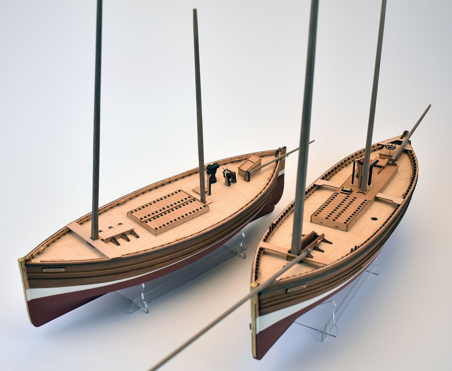
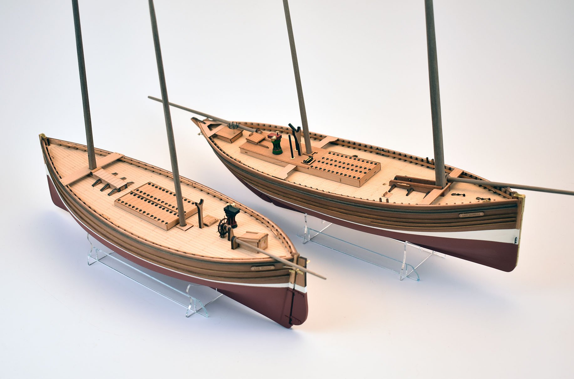
 Yes, that is the plan. (Assuming the whole world isn't in shut down mode by then..). I intend to release both the 80 foot Zulu (Lady Isabella) and the 70 foot Fifie (Lady Eleanor) together. There will be pre-made sail sets for both as an optional extra.
- 100 replies
-
- 16
-

-
- zulu
- vanguard models
- (and 2 more)
-
Bristol is most definitely going to happen, the decoration has already been sorted, plus the ordnance.
-
Agreed! After my third small/medium development (not counting the two small fishing boats), I cannot tell you how much I want to start doing larger kits. So with 5 kits available, these should help with the larger kit development and material costs. No day job today, am off sick - but no symptoms for the Corona virus, I think I am just a little run down...
-
Cheers If this pair sell OK, I will definitely do another one (or two) at some point.
-
Pre sewn sails are very expensive. I have never liked them anyway, from a personal point of view. So the thought of spending so much on sail sets (clearly, I cannot just order a couple of sets to be made, but minimum is 40 sets) is never high on my to do list. They do suit the smaller model though, especially subjects like the fishing boats, where the sail plan seem to compliment their 'character'.
-
Nice job, Glenn! Should have some more updates in a couple of weeks, just been beavering away getting though boring stuff. (drawings, sorting pics, waiting for sail sets etc.) I do have on order a powered miniature rope making machine, which should arrive in a couple of weeks.
-
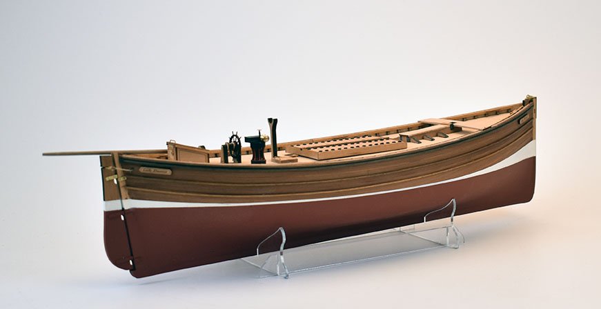
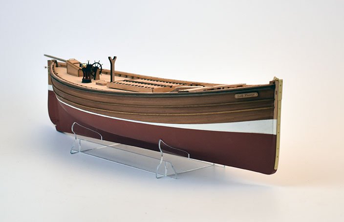
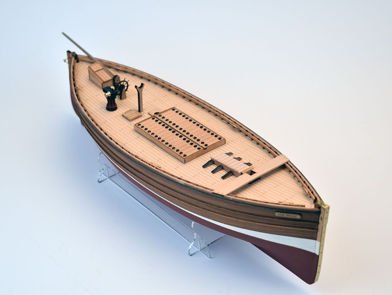
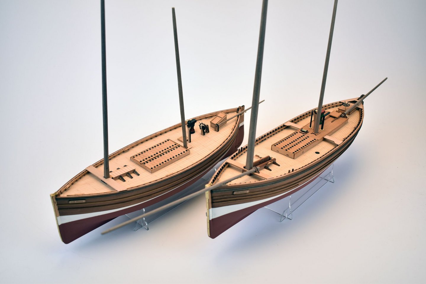
Thank you. Although it is designed to be relatively easy to put together, they aren't just for beginners. I chose the Zulu especially because it has some pleasing lines, and wouldn't look out of place in most homes, and wouldn't take up so much space.
-
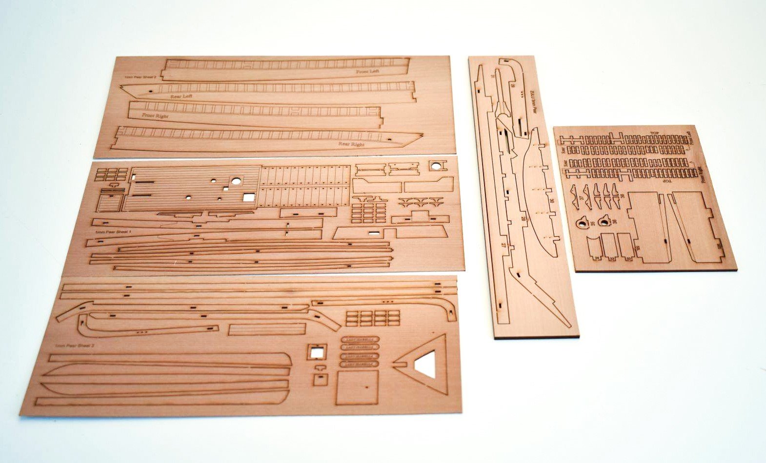
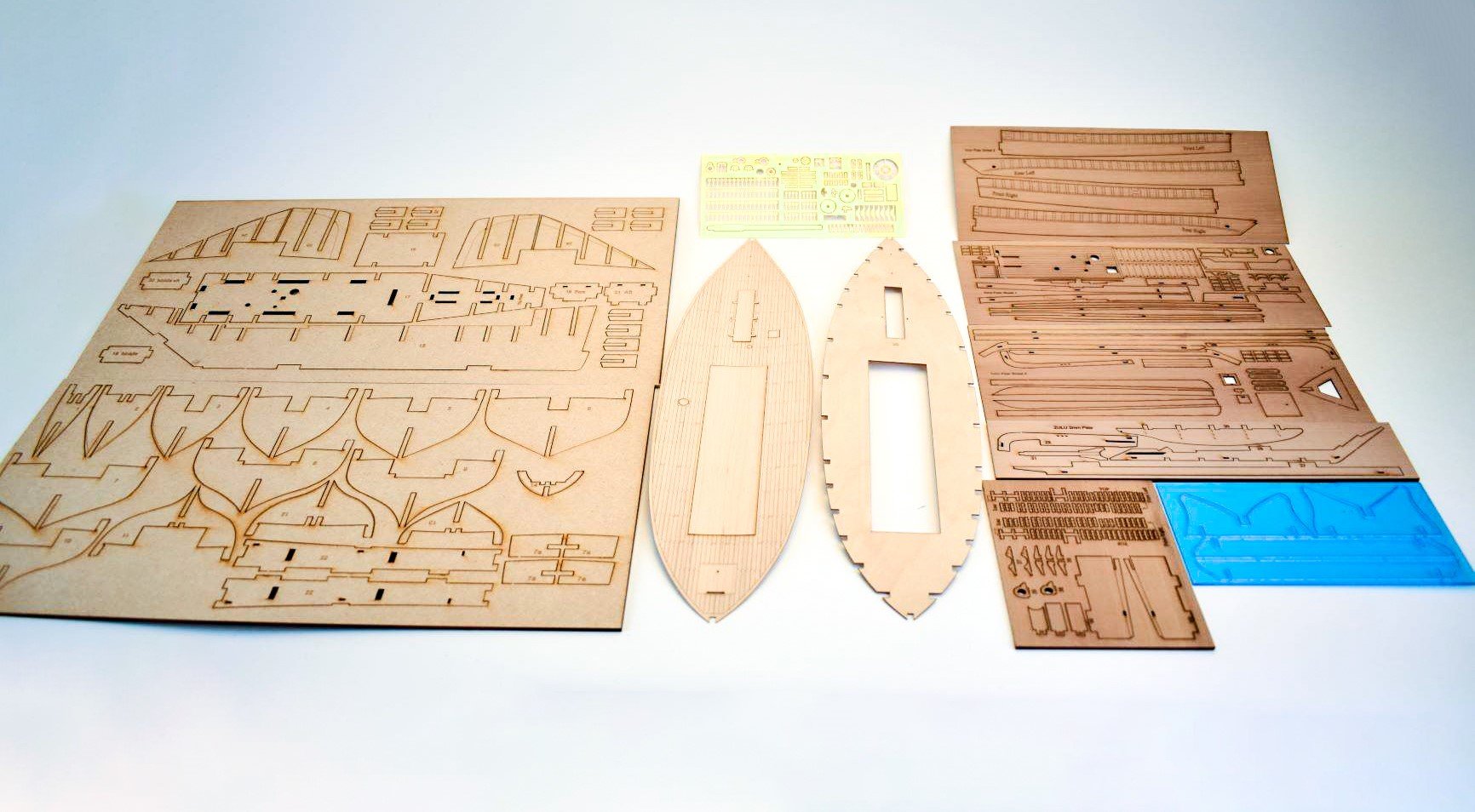
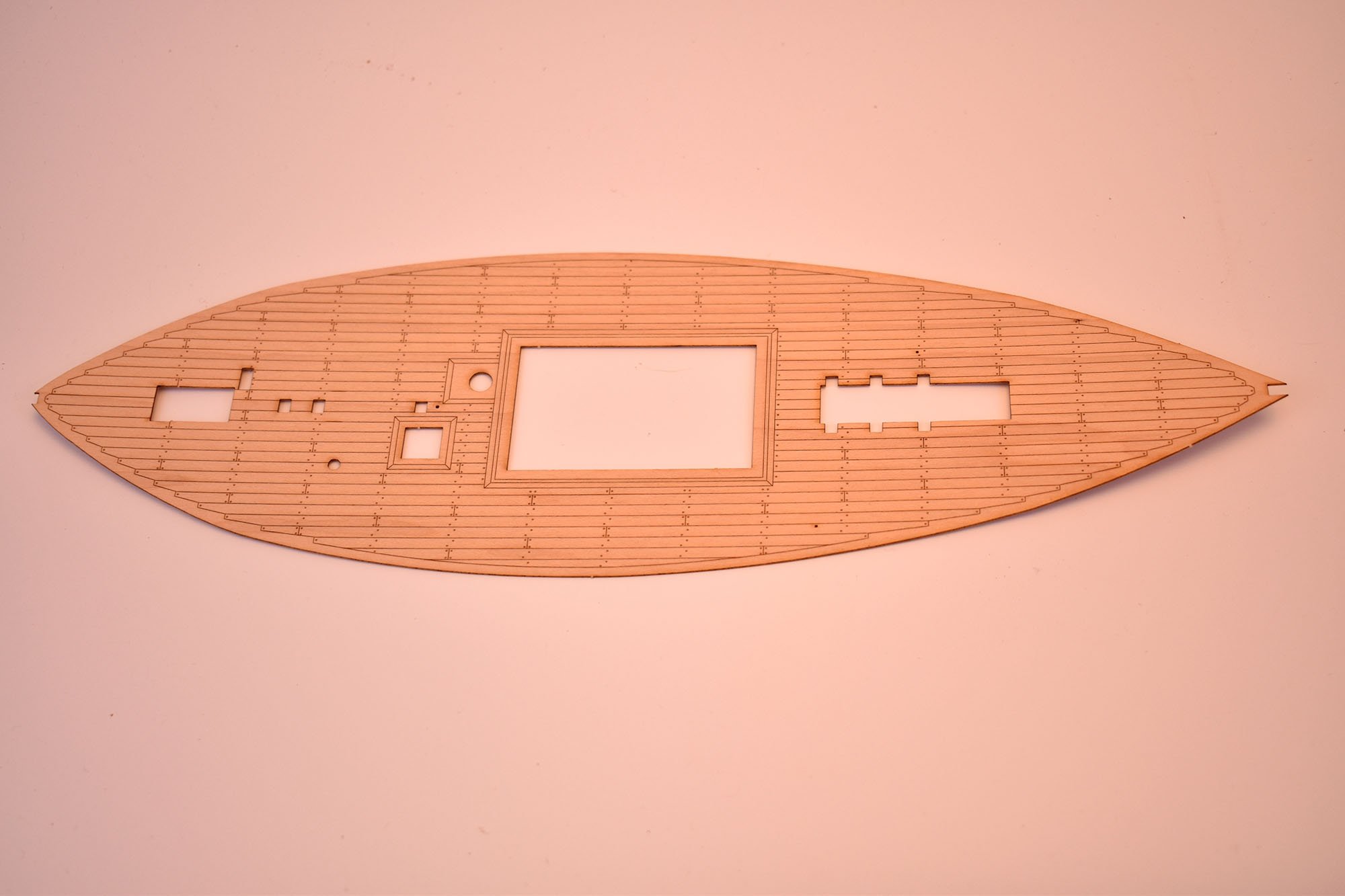
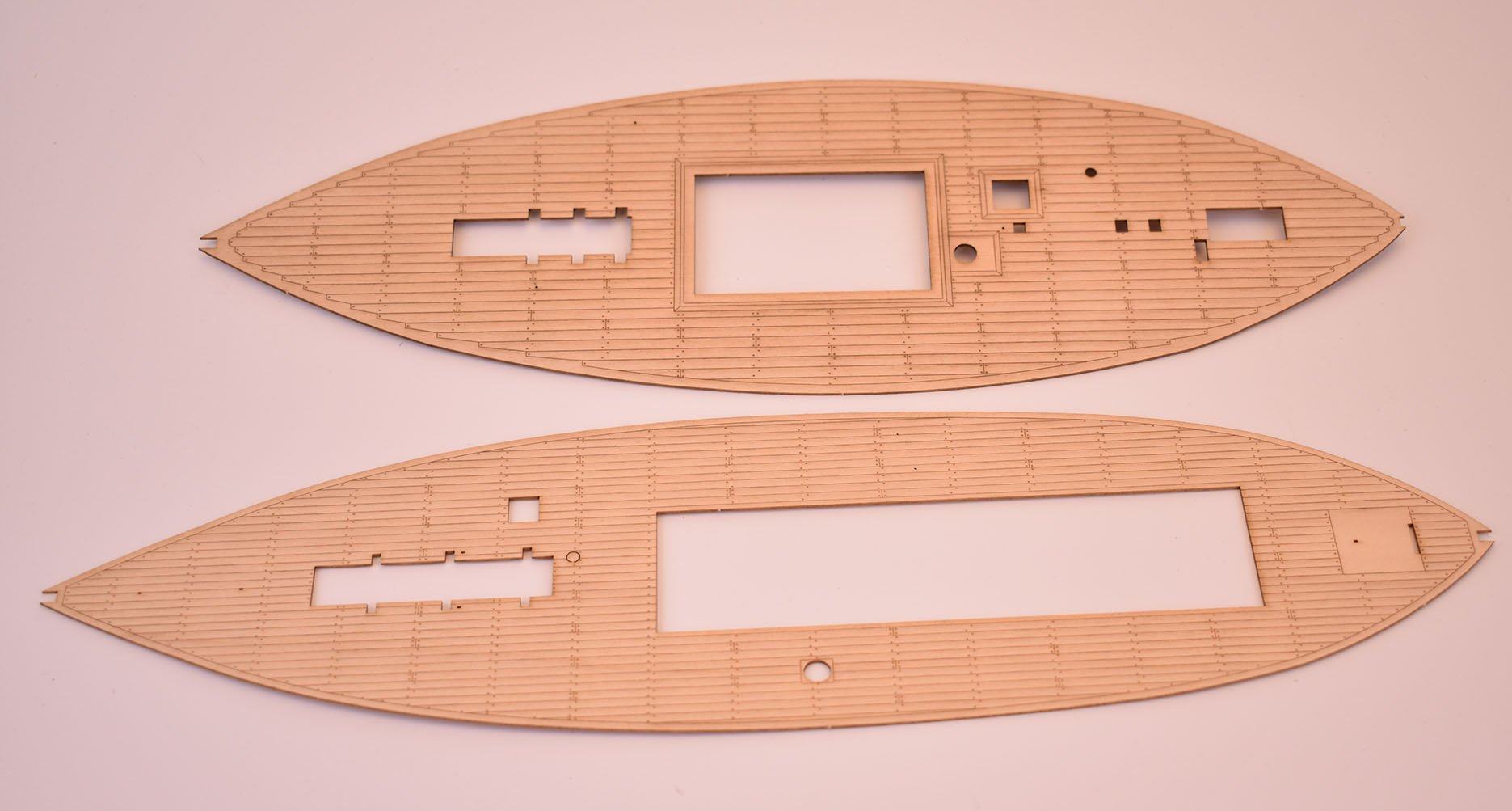
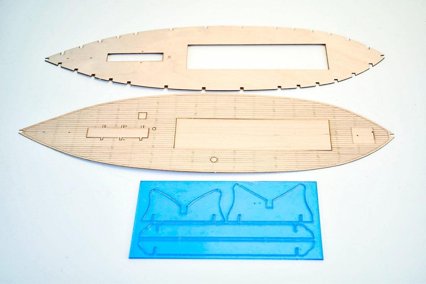
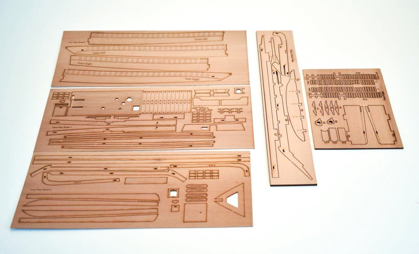
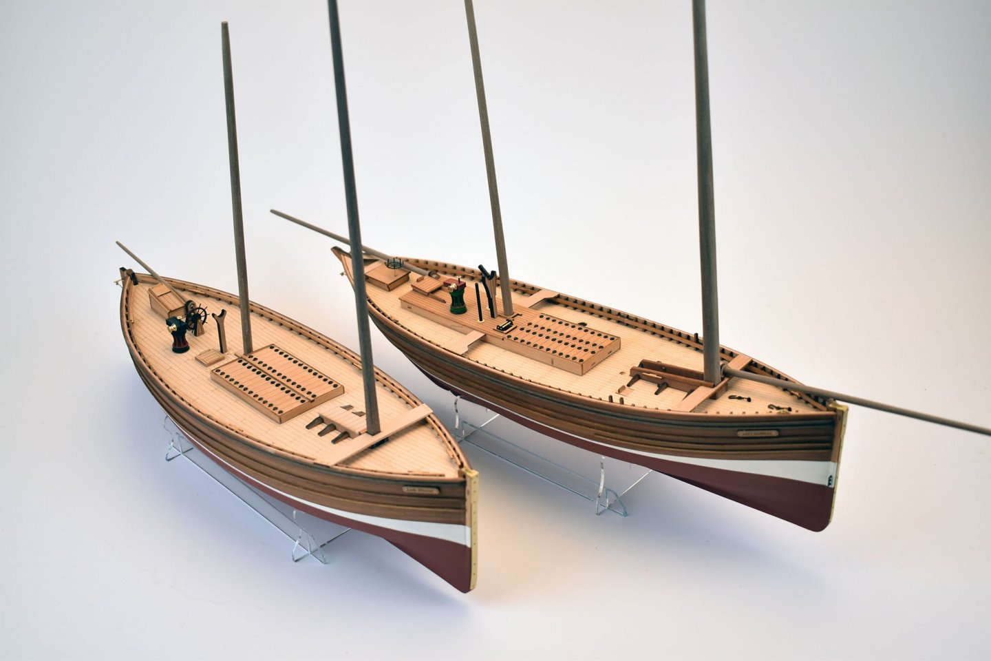
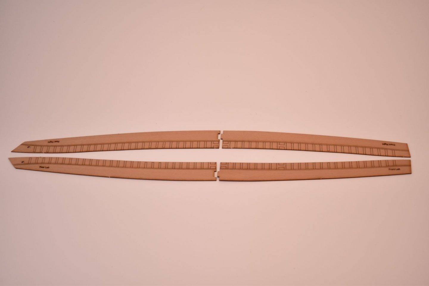
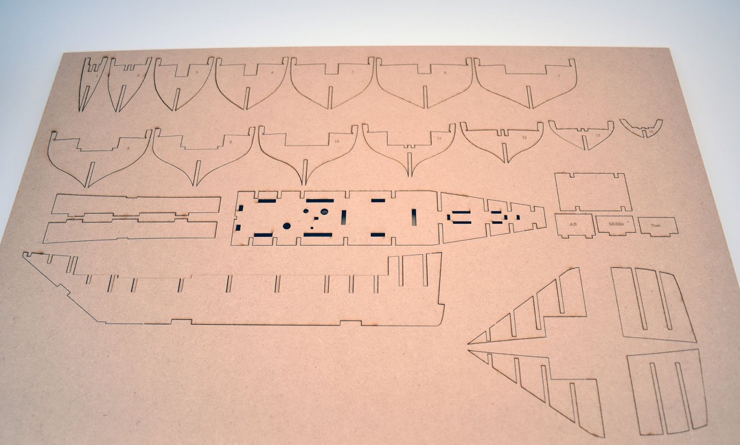
Here is the complete suite of laser cut and etched parts for the Zulu, Lady Isabella: 2 x 3mm MDF sheets 1 x 3mm Pear sheet 1 x 2mm pear sheet 3 x 1mm pear sheets 1 x 2mm acetate stand 1 x 0.8mm ply sub deck 1 x 1mm limewood laser etched deck (although the one shown is 0.6mm maple veneer, which may be an option) 1 x 0.4mm PE brass sheet

-
Thank you! I will certainly do another pair of small boats at some point, I have heard only good things about MarisStella and Syren, so you clearly choose well. I have never build a US based kit, all have been from the European manufacturers, but I am talking a long time ago since I bought and built one of those kits. I always remember thinking that no matter what the subject, they always seemed to look very similar to each other when built, always the same materials (that really needed replacing), same fittings etc, even for ships that were 100 or 200 years apart from each other, historically. In my mind, I still equate 'Beginners Kit' to cheap 'n' nasty, with emphasis on getting as many sold as possible, even though the modeller would really need to replace most of the kit contents, easily doubling the initial price, if they wanted a fighting chance of doing a decent job. I am talking a couple of decades ago, so not sure if things have changed... Cheers - but next time, let me know and I will send you more planks, I really wouldn't have minded at all!
-
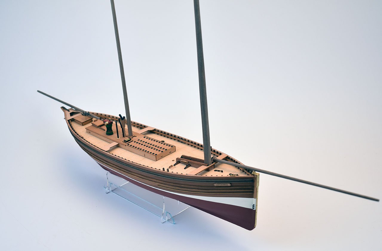
Thanks! Scale is 64th, I think the one I did for Amati was 35th scale, memory hazy. Both these new (and smaller) kits are pure sailing vessels, with no motor. I have been in contact with James Pottinger, an expert of these vessels, to help get the details and overall look right.
-
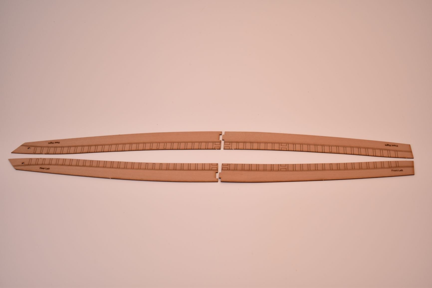
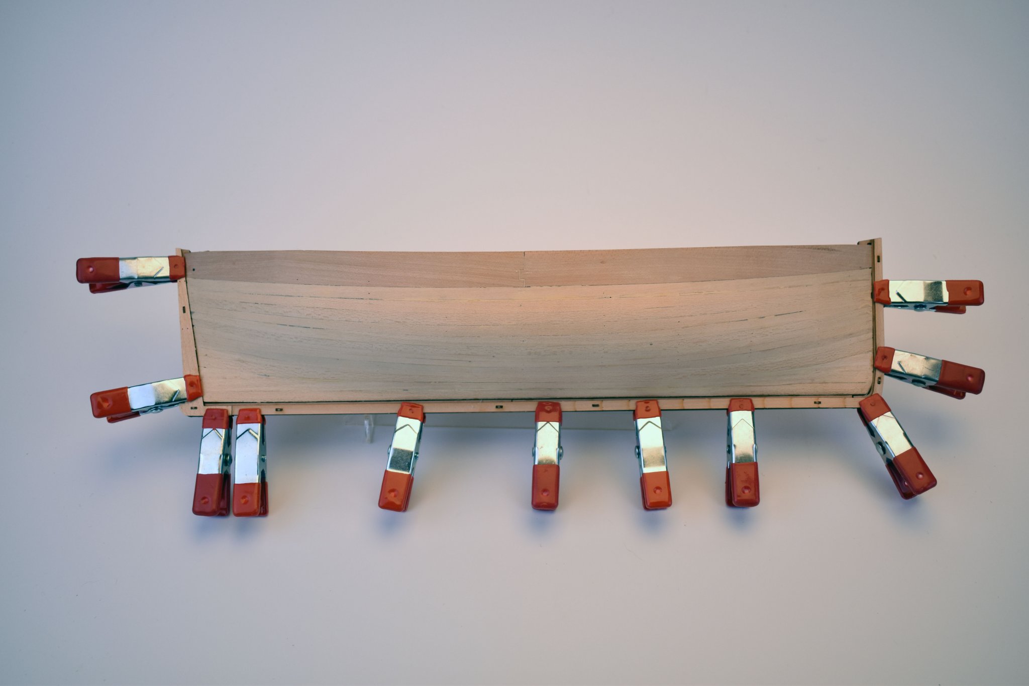
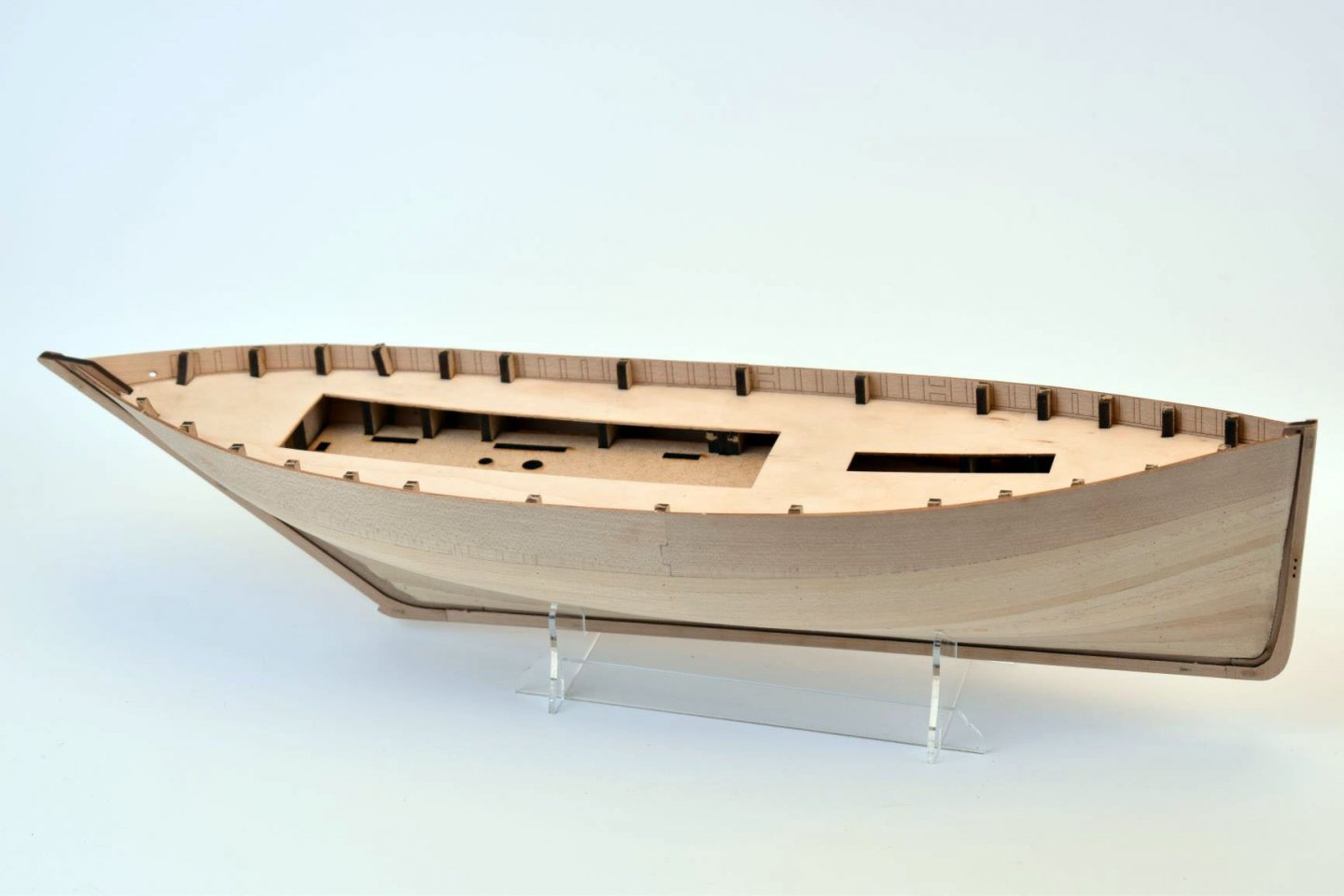
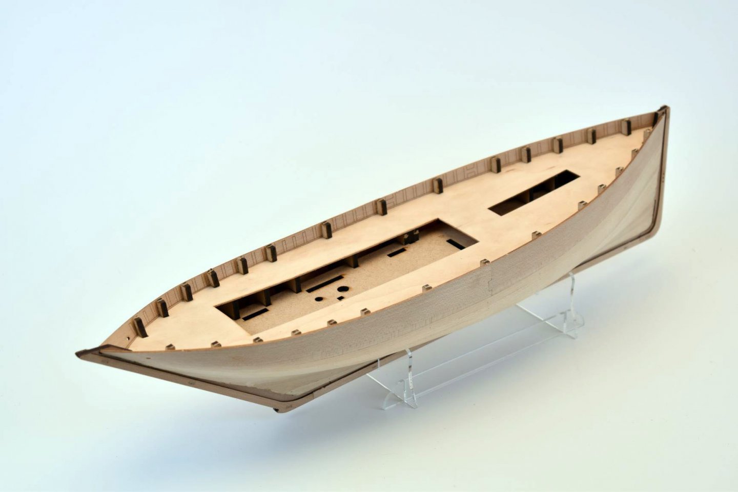
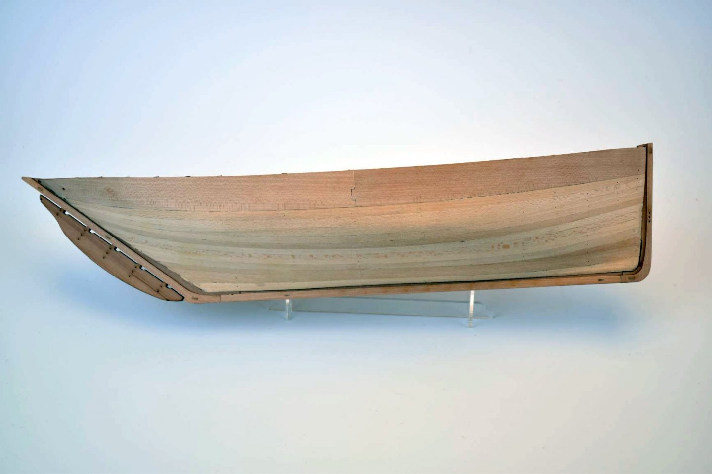
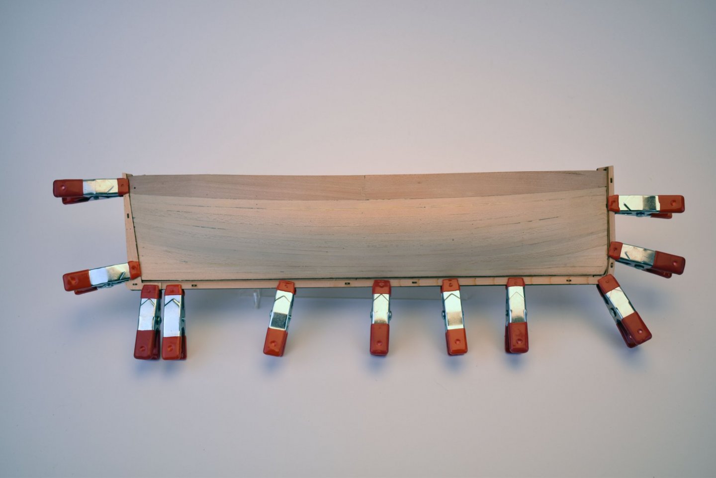
Cheers :). If anything, at least these helped me get to know my laser machine and it's capabilities (and mine) a little better. The bulwarks are fine, the pear worked great once soaked for a few minutes, a lot better than I first thought, in fact. If it didn't work, I would have just planked the area from the top of the bulkhead tabs down to the keel. As it is, however, the pear is very pliable and I had no problems just dry clamping them in place whilst the glue dried..
-
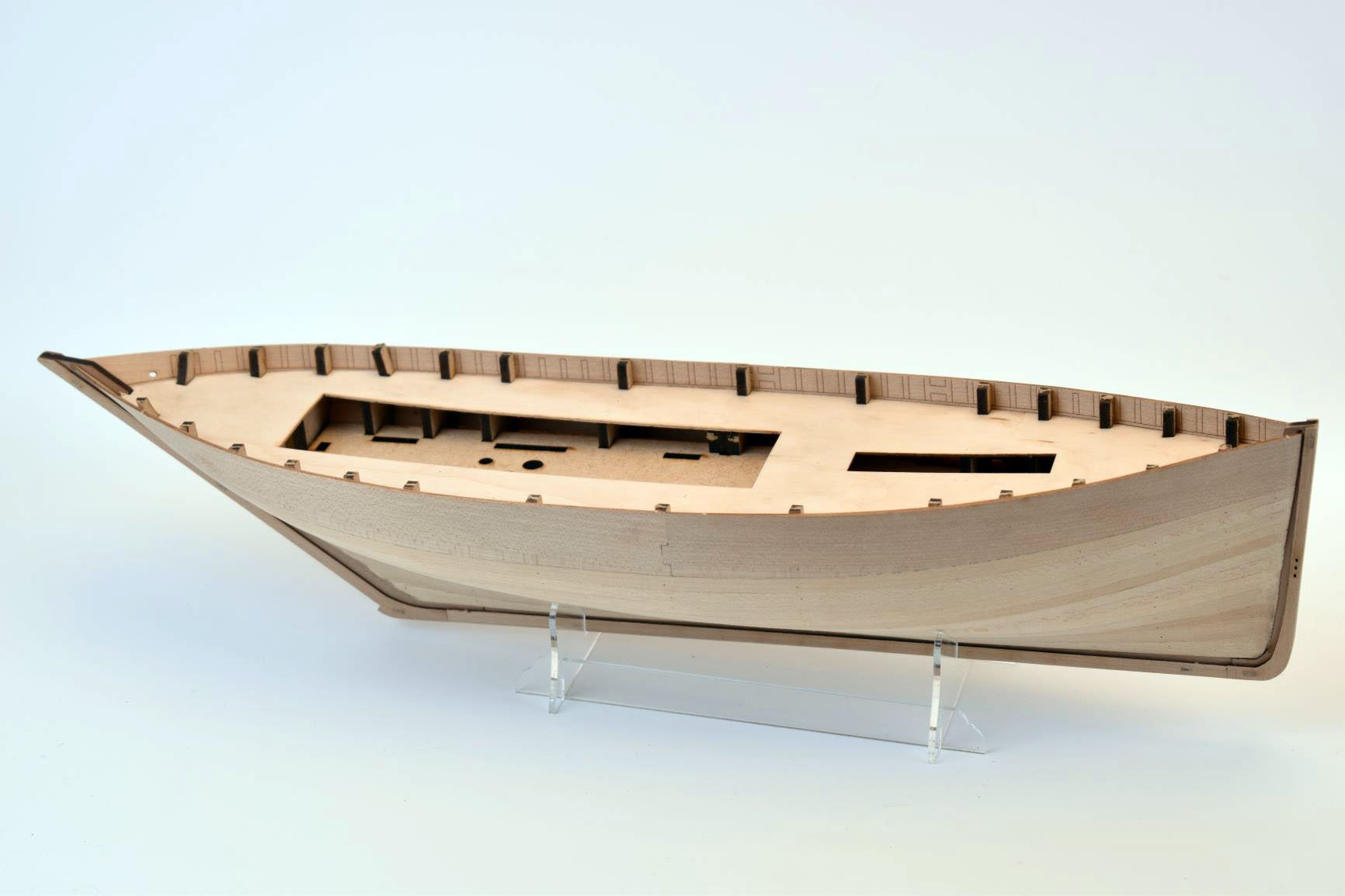
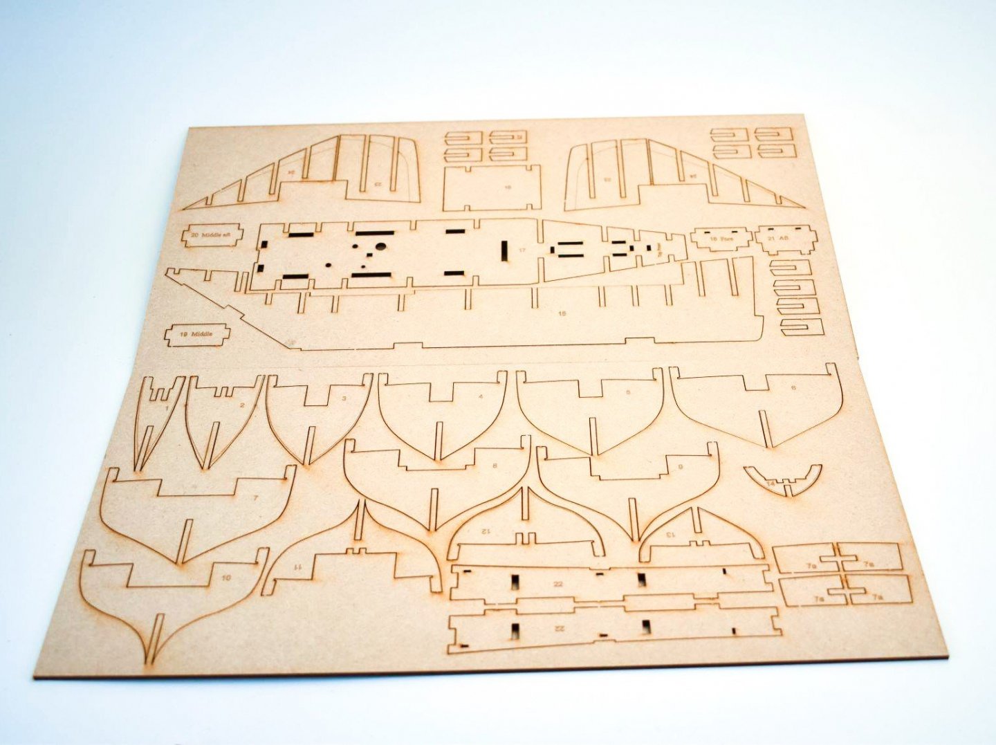
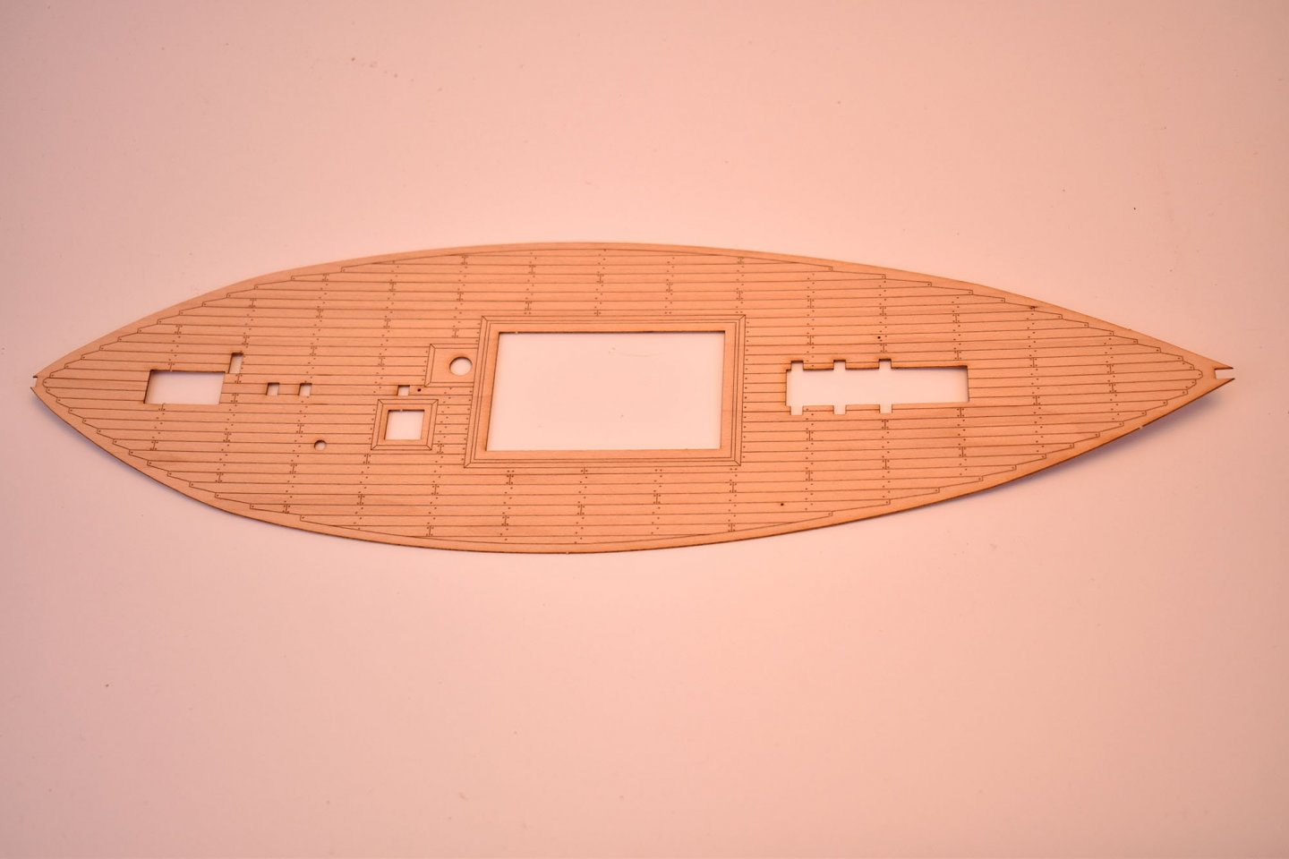
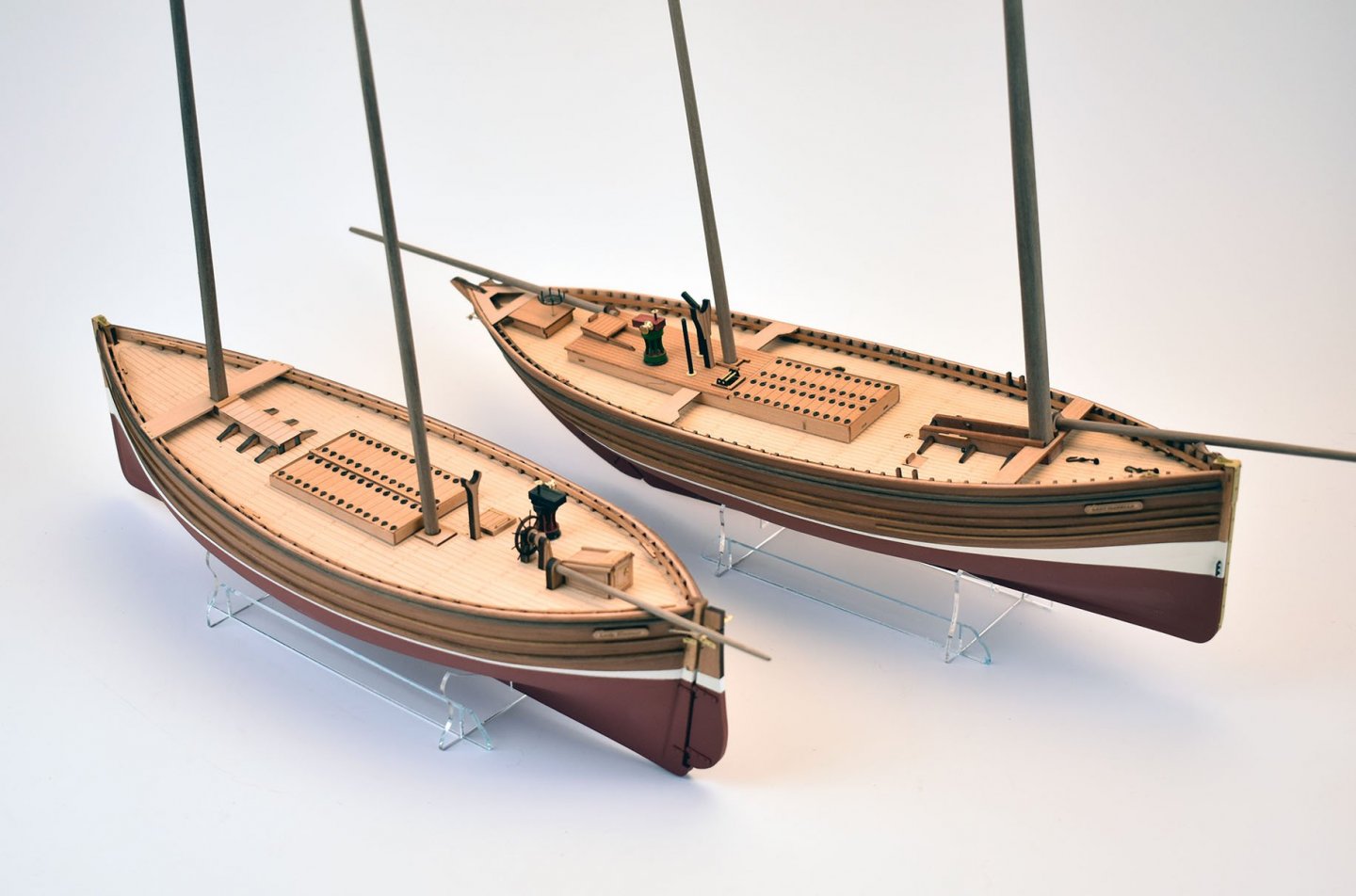
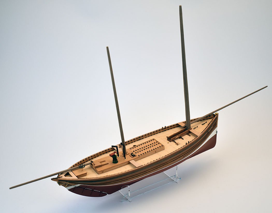
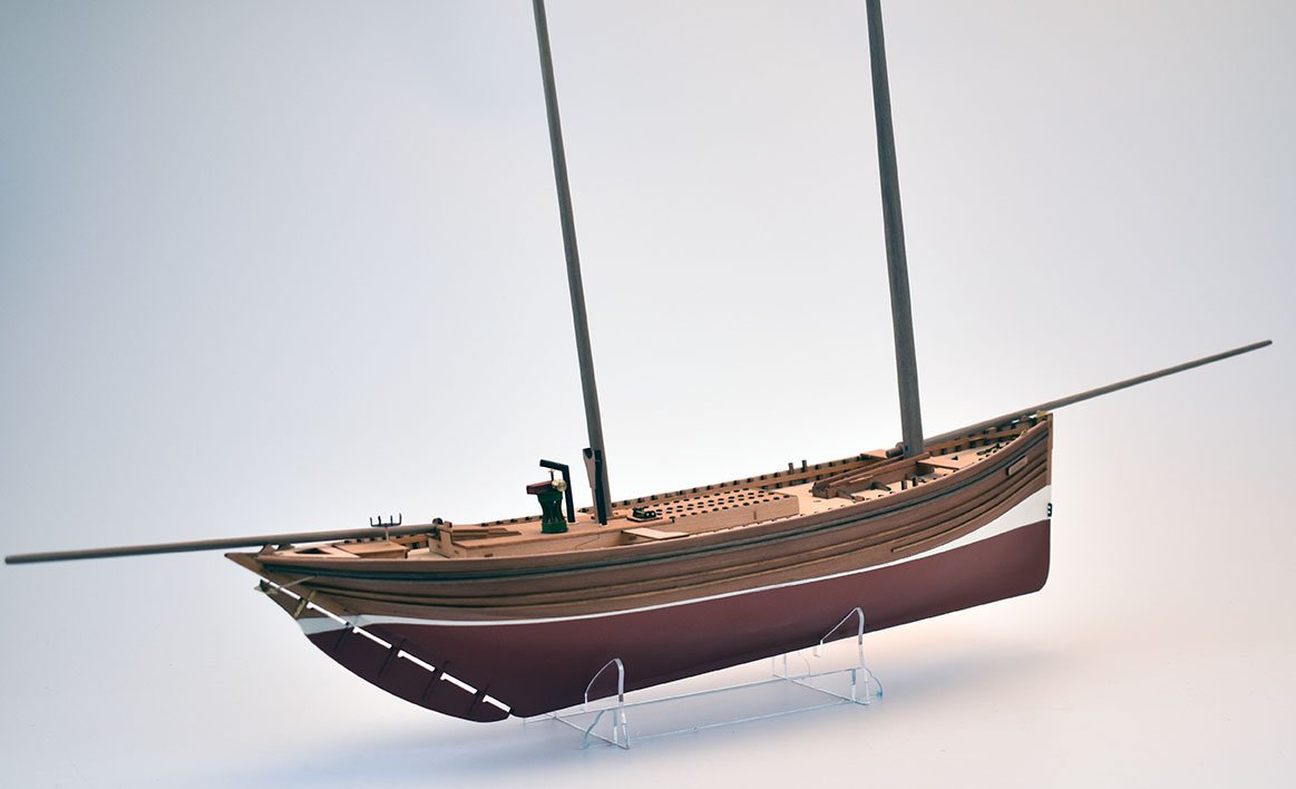
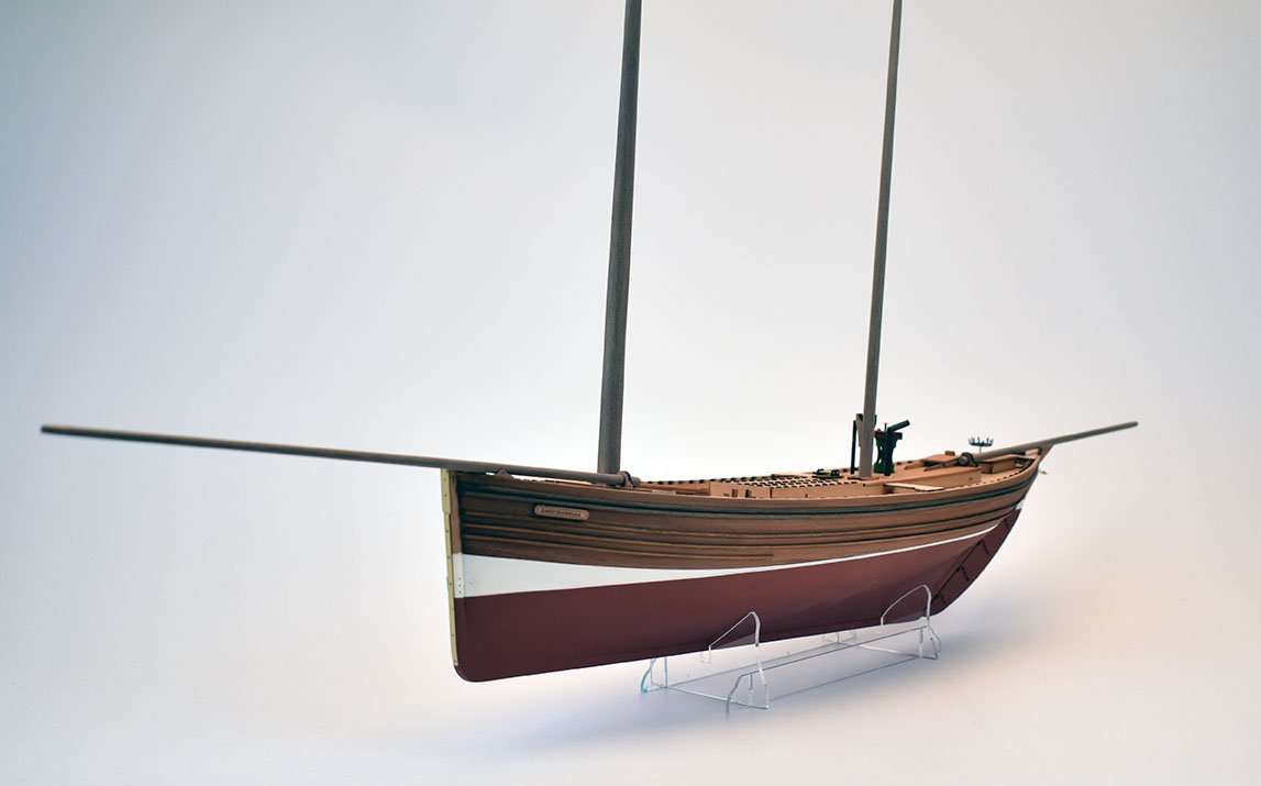
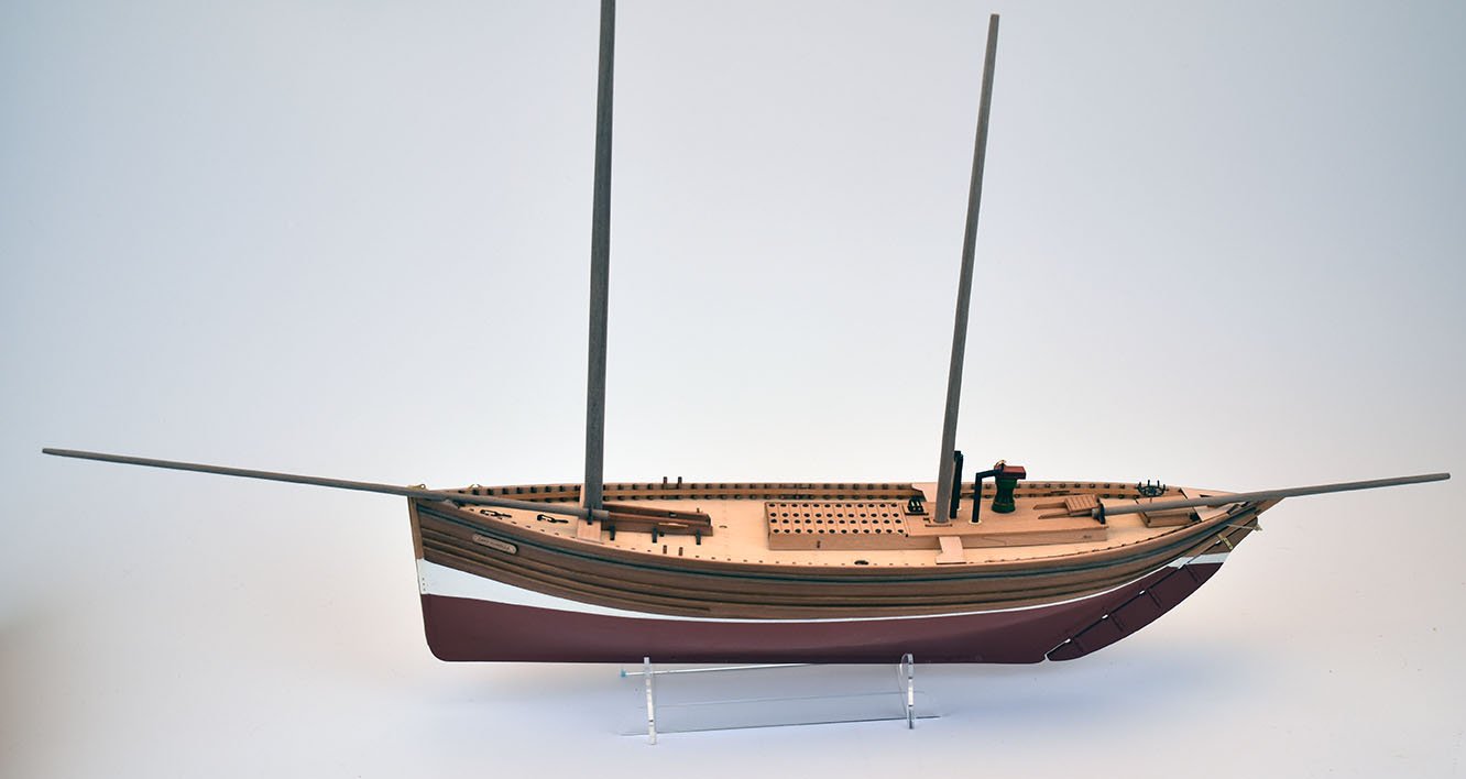
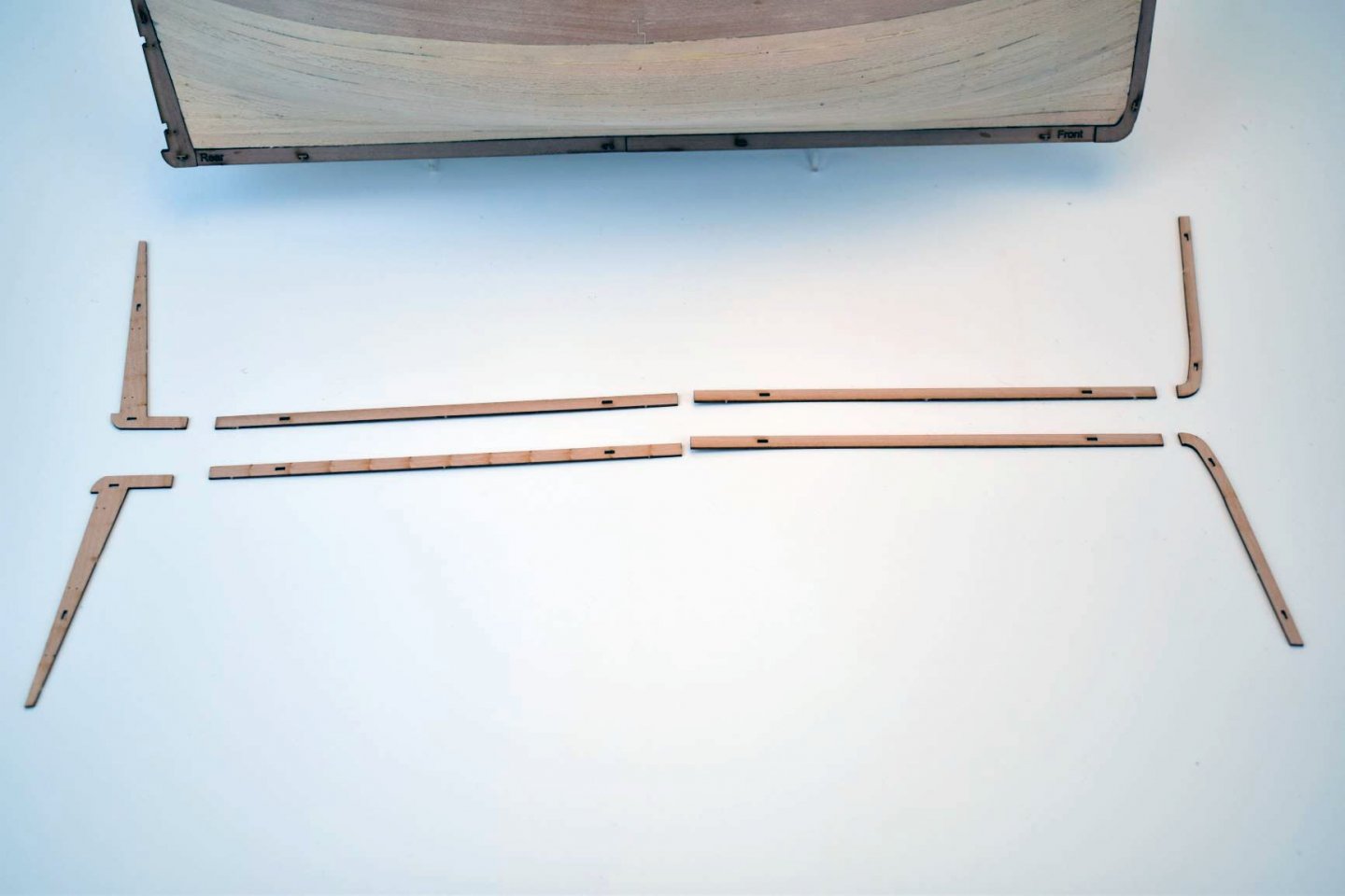
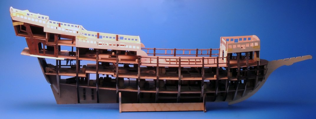
Haven't updated for a while, but I have been busy, overtime at work, and me deciding it would be a very good idea to develop one simple little beginners kit, no problem, I thought... Things never quite work out how you first envisage, however. I thought I would do the minimum for beginners kit, making it cheap and easy. But I just couldn't help myself, and kept adding more parts and using better materials. These are the first kits I have done so all design and laser cutting is done completely in-house. My initial reason was for me to get used to my laser machine, rather than working on something more complex, do something a little simpler. I had intended to do just the Fifie, but I saw the lines of a Zulu and figured it would compliment the Fifie perfectly, so I decided to develop that too, in concert with the Fifie. The (80 foot) Zulu is named Lady Isabella and the (70 foot) Fifie is called Lady Eleanor. They are both late 19th/early 20th Century Scottish fishing vessels, built for the rough northern seas. The Zulu has around a third more parts than the Fifie, but both follow the standard designs, but with more helpful stuff added for beginners. Both have a laser etched deck, laser cut skeleton in MDF (tried poplar ply, too weak and birch ply, too thick, well over 3mm), and the rest of the wooden parts are all pear wood laser cut, with the decks being in 1mm limewood. Each has a brass PE sheet, first planking in 1x5mm limewood and second in 1x4mm pear wood, and masts, spars and a couple of other things in walnut. I am just waiting for my sample pre-stitched sails to arrive, two separate sails for the Fifie and three for the Zulu. I figured that just because it's aimed more at beginners, that doesn't have to mean it should be just a box of cheap crap, but hopefully, a project most can enjoy without much bother. The pic of the bulwarks show the inner sides, with all positions for the pre cut timberheads above deck level marked out, so no need for measuring. And this is where I am up to. I am currently laser cutting the wood files, as all have now been added to the prototypes and all are good. All this because I thought it would be a good idea to quickly develop a cheap little kit...


-
I too am not so keen on the copper, I prefer the off-white for the overall aesthetic. OK, I have been working on these two small kit, partly to try an nail some new aspects of design. Especially the way the second planking meets with the keel parts. With this very much in mind, I have designed these kits with a 'beading edge' to be glued into position all along both side of the keel after the first planking has been applied. I have included little location pegs for each pattern, so there is no chance of any of the parts slipping/moving while the glue cures. I think it will work, but these two models are double ended, which means the modeller will have to be very exact with their plank lengths or, as I will likely suggest, lay each plank in two lengths, starting each and the bow and stern..
-
This was my first ever wooden boat kit, I bought it in the very early '90's. back then it was the same as shown above, where you plank the two halves of the hull and then glue them together once each half has been planked. A great first kit as the hull is quite 'box-like'.
- 83 replies
-
- 1
-
-
- finished
- billing boats
- (and 1 more)
-
It is always 'heart in mouth' time when it comes to removing the deck after dry fitting. The ply is very flexible, though, so I always make sure I bend the deck almost to a U shape, to clear the slots of the tabs. I did think about splitting the deck in half, but I think the inherent strength of the complete deck, once in place, trumps the minor difficulty on removing after dry fitting.
-
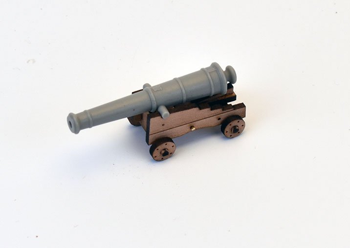
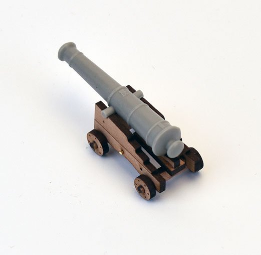
Yes! lol I tried the round versions for the new 24 pounders, and they seem fine, so will change all square holes to round for future cutting. Problem could be when you have 26-28 carriages to make up for each deck, that is a lot of axle filing to get them to fit through the round holes..
-
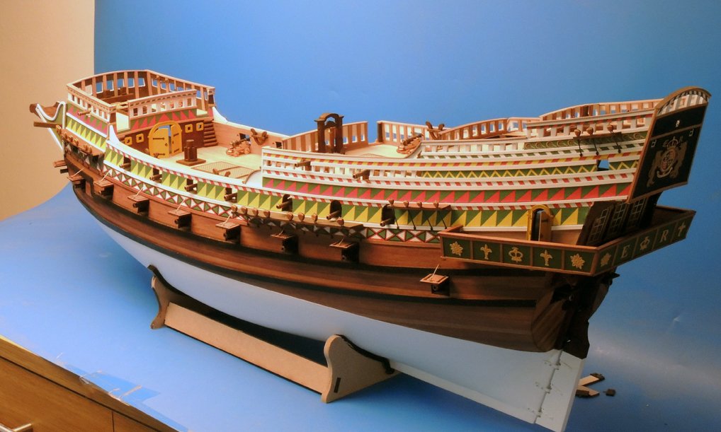
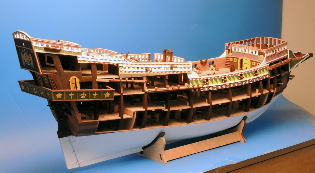
Very nice. I think this was the first design that got me more interested in adding internal detail. A few years later, I developed a much larger version (48th scale I think) of a completely reworked Revenge, with a lot less sheer/curve to the decks and bulwarks.

- 65 replies
-
- 13
-
-
There are a few frigates I would like to do right now, to be honest, and my potential future development plan has 4 in mind. I wanted to develop one next, but I have spent quite a bit on Bristol/Portland Class development already, and need to do this/these first. (stern and figurehead decoration already done, plus cannon barrels) Cheers I am adding these 'bolt heads' in the trucks to all sizes of carriage parts now.
-
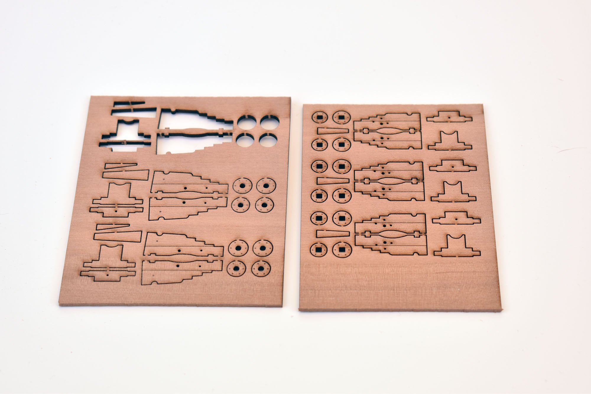
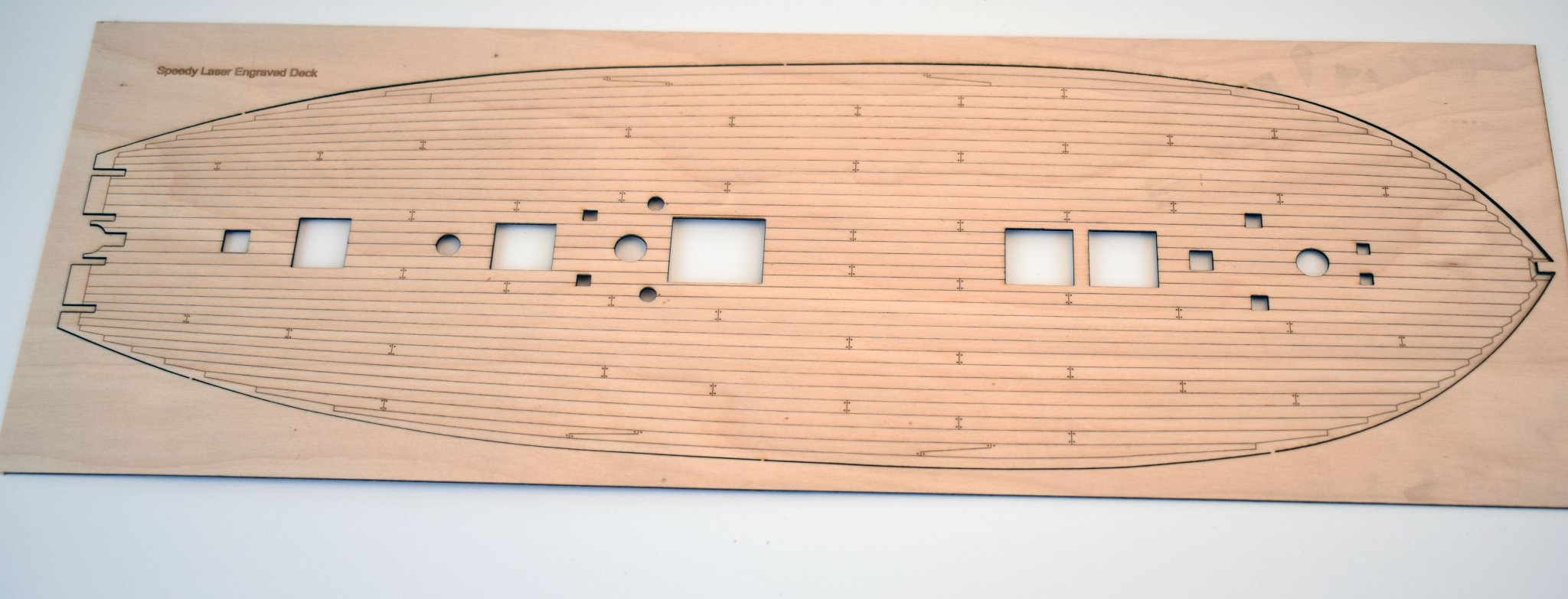
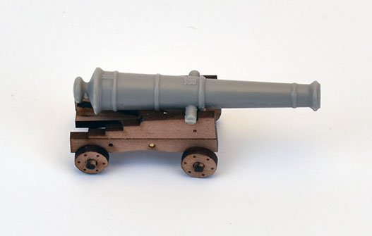
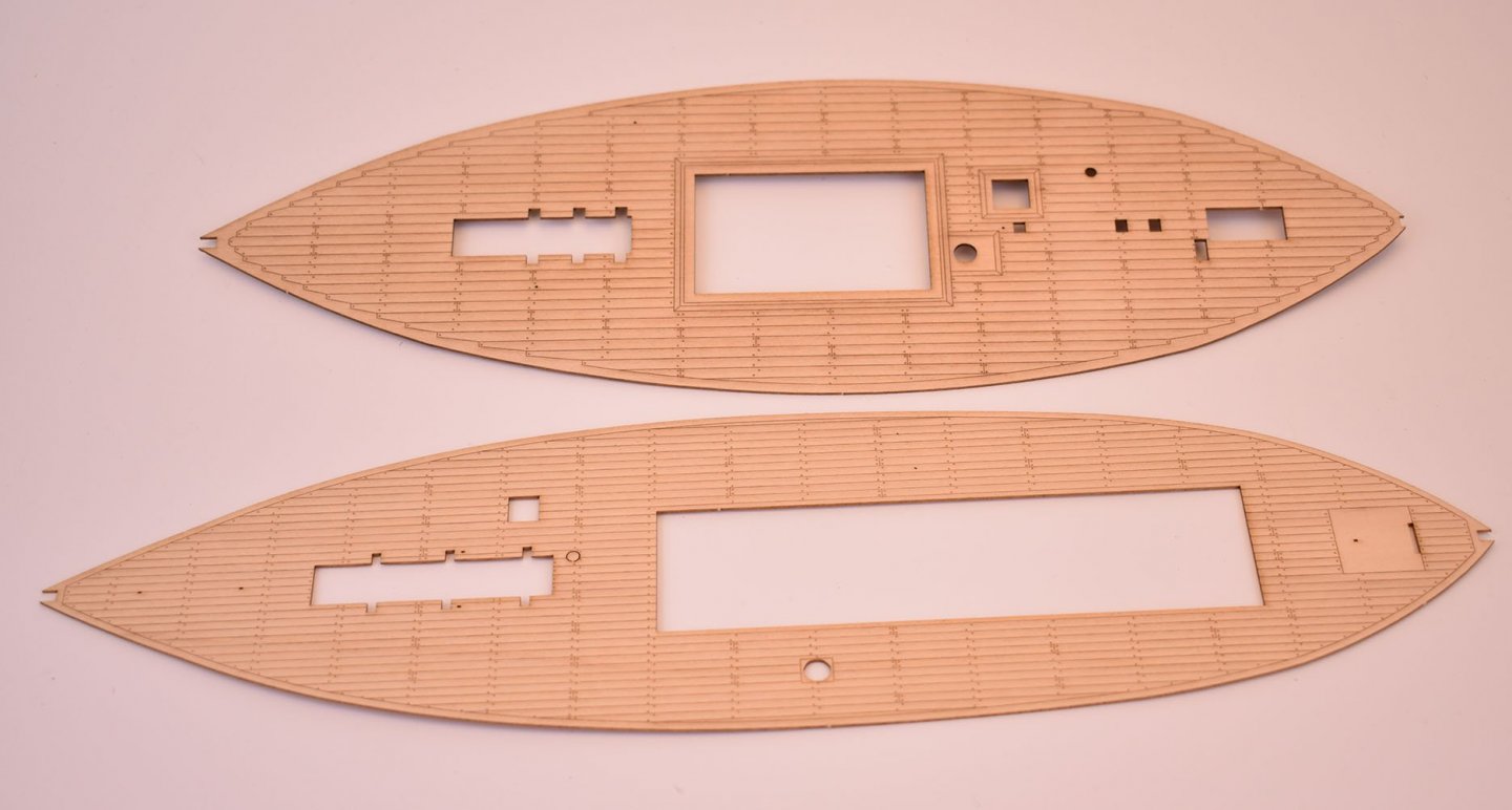
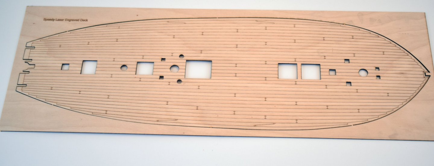
Yes, the laser etched deck was amended, I have attached a pic to show this. I have mostly been getting on with the two small kits, but today I turned my attention to the Bristol and other vessels cannon carriages. Attached is a pic of the Bristol (64th) 24 Pounder carriage, laser cut and etched in 2mm pear, with the cast resin barrel. The pic showing the laser cut parts in the sheet are the 24 pounders (the larger of the two sets) and 32 pounder carriages in 72nd. I have done a few gratings sets too, plus the decks for the two small kits, which I have shown here, as this is their final kit form.

-
I just use common or garden water based 'medium colour' filler, which I buy from my local DIY shop.
-
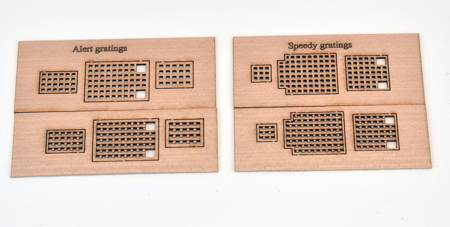
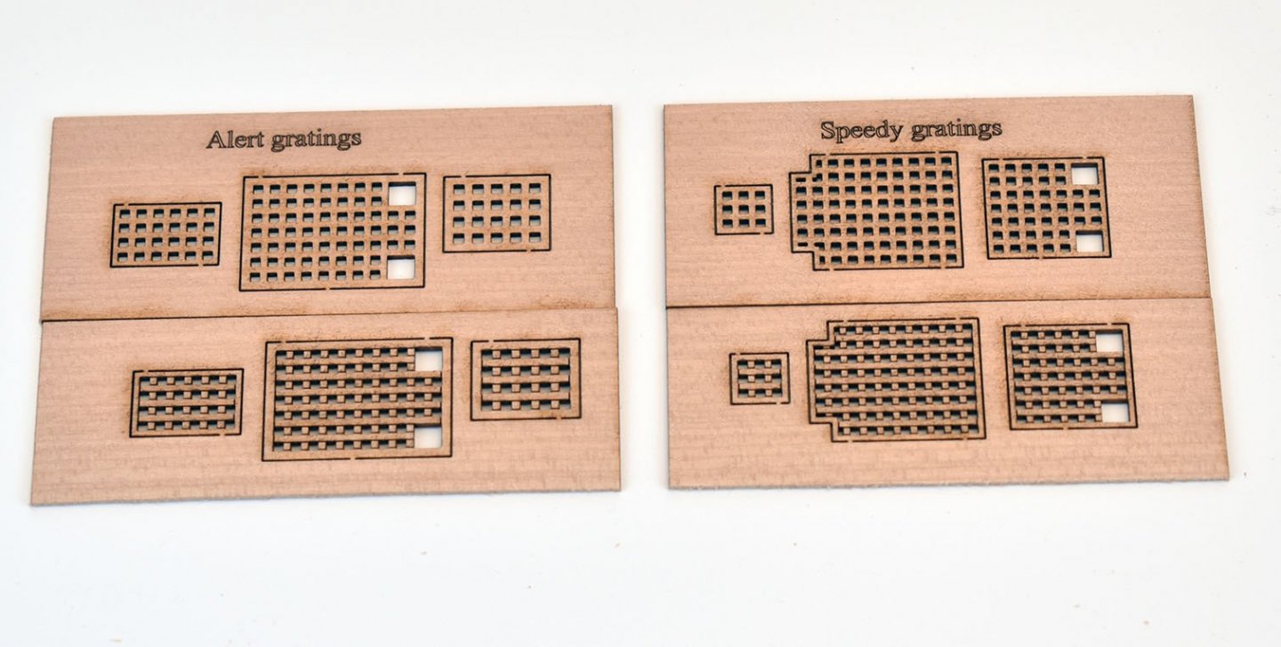
Cheers I never thought of laser cutting the gratings until a few days ago, as I know I tried it before, years ago, and the laser machine 'nuked' them( they looked like debris from L'Orient after she blew up at the Nile), so I figured the same would happen again. Plus it was too expensive when having to sub-contract anyway (as was adding the treenail marks in the etched decks). However, all new developments that have gratings will be laser cut. Regarding the laser etched decks, I do like the look, and think they suit the smaller vessels (and help out the more novice modeller, who only has the hull planking to contend with). The problem with plywood (my preferred choice) is that half of every batch I buy is not suitable due to natural imperfections. The scrap rate is unacceptably high (I can still use the ply for all other laser cut ply parts, but not for decks). Even then, if I have to cut the etched deck in an area that has the fewest marks, this may be slap bang in the middle of the plywood sheet, rendering the rest of it unusable for anything else. I know that limewood is a lot more reliable, surface-wise, and does look nice when matt varnished for decks (I have seen dozens of models with such planked decks). Tanganyika sheet would be OK (colour-wise), but it would be a lottery as to whether the grain is too heavy or not in certain batches, as I know this particular wood quality varies from good to darn awful. I do advise that low tack masking tape is applied to the top surface of the deck until all hull and bulwark planking is done
-
I am sure I spend half of my entire development time trying to think of the most easy and painless way a customer would like to put the parts together. I sometimes stop one aspect of the design and end up thinking about it for days before trying a few variations..
-
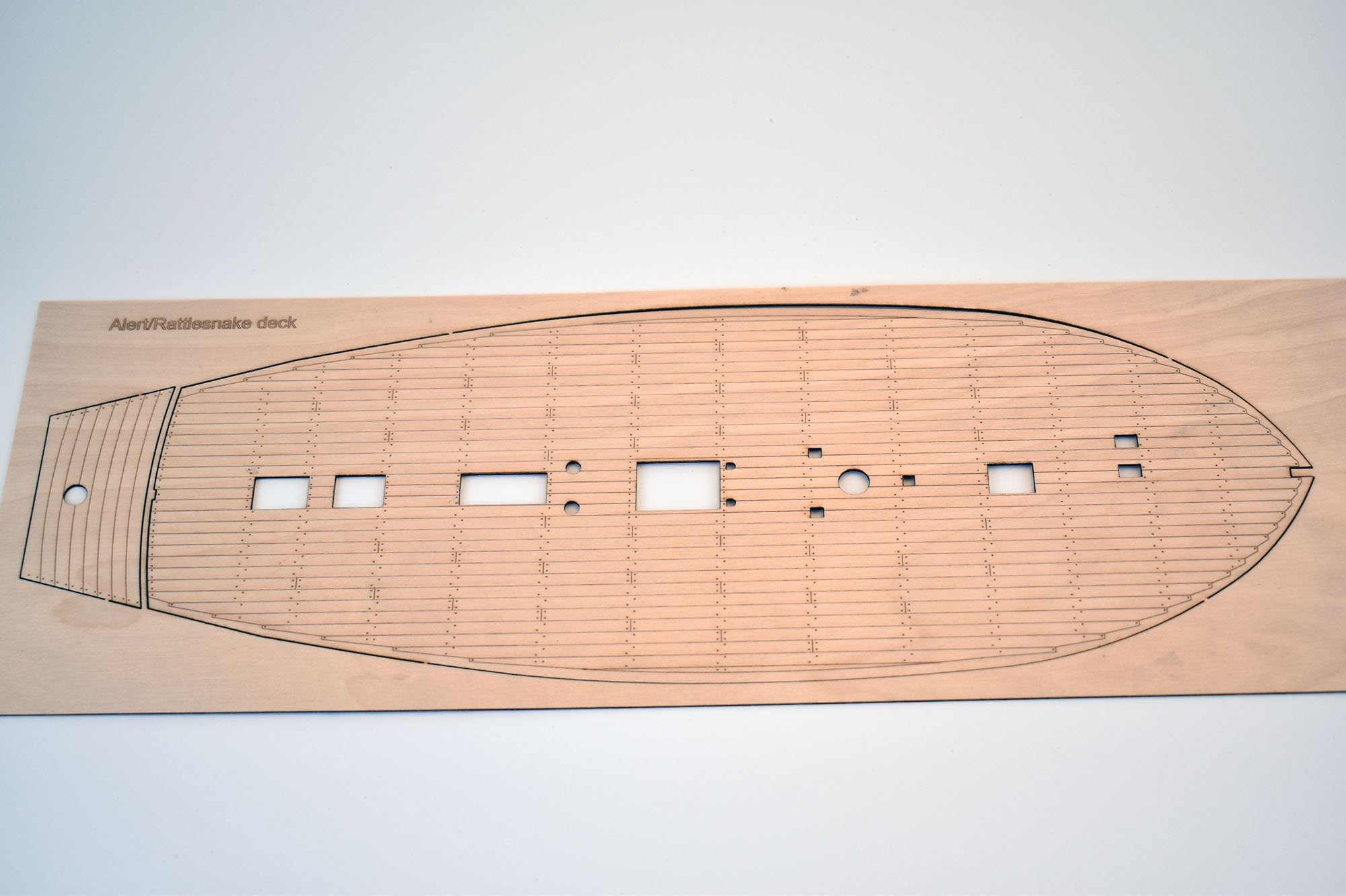
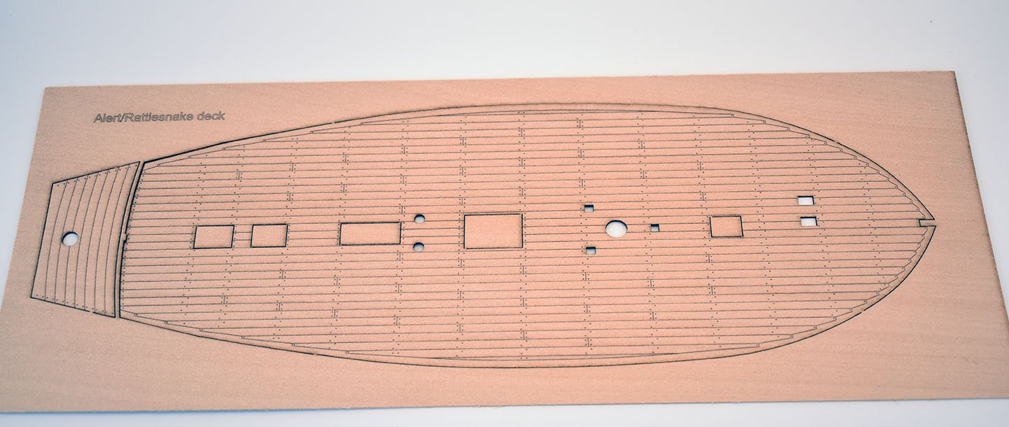
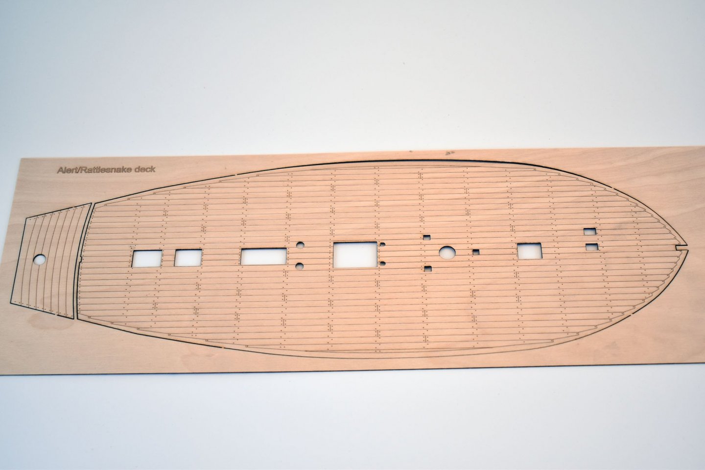
I have added the grating sets for Alert and Speedy to the website: https://vanguardmodels.co.uk/product-category/fittings I don't want to add the Alert deck yet, as it is really intended for Alert's sister, plus I want to see what they look like in limewood instead of the ply. however, if anyone would like a deck, contact me and I am more than happy to do them as one offs.
-
Thank you! It is a learning curve for me, and I find myself plunged into the deep end of certain aspects of processes I have thus far not had to worry about. I am not really a true 'businessman', but a designer, so am pretty crap with migraine-inducing sales patter. I am just happiest when designing the stuff I like (and hopefully what others would like), and trying to design the parts in a way that people will enjoy putting together. Also learning a lot about box art, manual layouts etc. they will get better.. OK, today I have no work (main job..). So I managed to re-design the Alert and Speedy laser engraved decks and also design the PE gratings so they can be offered as laser cut pearwood parts. These came out a lot better than I thought they would and will be laser cutting gratings in all new developments. I did two sets of each, one with just laser cutting and the other set, which I think looks better, both laser cutting and engraving. They haven't been cleaned up in any way, that is how they looked when removed from the laser machine (I ordered a special air nozzle for the laser, which focuses a more direct air flow on the parts the laser cuts, so less burning) Is it worth offering these as an optional extra? I ask because I cannot really included them in future kits until I run out of the original PE parts, then I can remove them and replace with the laser cut pearwood versions. Is the Alert/Rattlesnake deck with laser engraved planking and treenails OK? I will most probably develop Alert's sister at some point (not for a long while though), and will use that deck. The Speedy deck has all hatch bordering removed, which was done quite a while ago, so should be filtering into the latest kits. I was hoping to cut these on my new 150mm limewood sheet, which should have arrived today, but didn't. So these are cut in 1mm ply. Finally, a pic of my very latest, the second of my little 'beginner' kits. These are very first to be cut, to check basic overall fit. I am hoping these two little kits will have optional pre-made sail sets in the exact same quality as the Master-Korabel sail sets. Right, back to checking these little Zulu parts...
-
Cheers guys I am currently working on 2 beginner kits in concert, am hoping these won't take that long. I have also designed a laser engraved deck for Alert/Rattlesnake, which I plan to cut a sample of later.