
HOLIDAY DONATION DRIVE - SUPPORT MSW - DO YOUR PART TO KEEP THIS GREAT FORUM GOING! (Only 24 donations so far out of 49,000 members - C'mon guys!)
×


Javelin
-
Posts
624 -
Joined
-
Last visited
Content Type
Profiles
Forums
Gallery
Events
Everything posted by Javelin
-
 So Mark, you're Sphinx is finished... Time to continue work on this gem maybe?
 -
Hi Johny, the flags don't mean anything, the triangular ones are pendants, they signify numbers and double/triple etc of the letter before or after them. considering they are alternated with normal signal flags shows there is no meaning. It is also normal to have the flags in this order, which is meaningless in any language to avoid offending anyone during a port visit.
-
2023 Donations drive
Javelin replied to James H's topic in Using the MSW forum - **NO MODELING CONTENT IN THIS SUB-FORUM**
I also made a small payment. More of a test to see how this works. -
Brilliant work Glen, fantastic display of perseverance. With my limited bottle experience I can already imagine what you went through. And this build went really fast, you overtook my build in no time and with such great results. I also love the way she fills the bottle, not too large, not too little.
- 290 replies
-
- 4
-

-

-
- Quinquereme
- Finished
- (and 1 more)
-
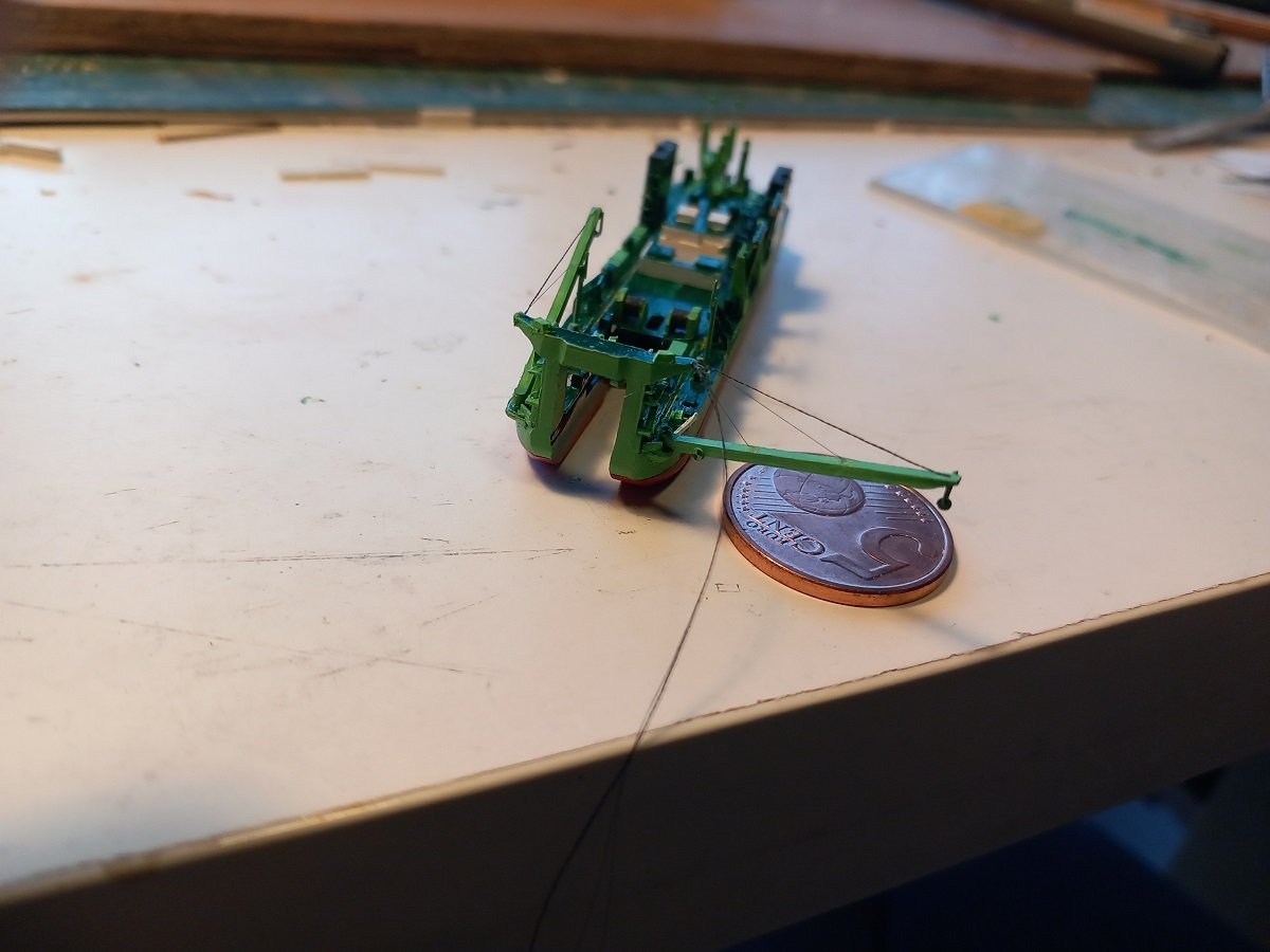
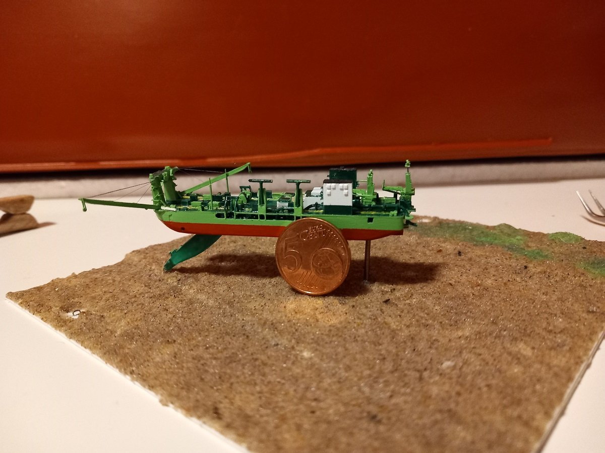
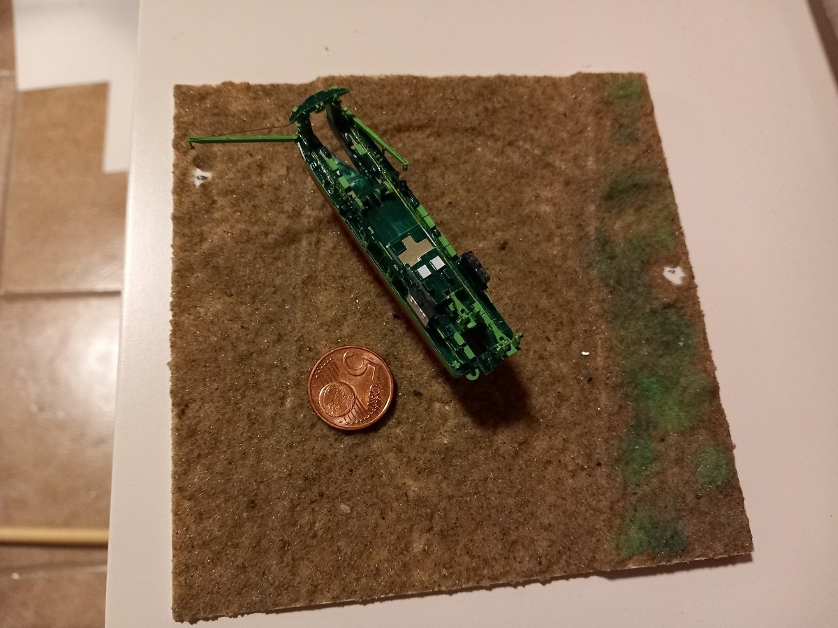
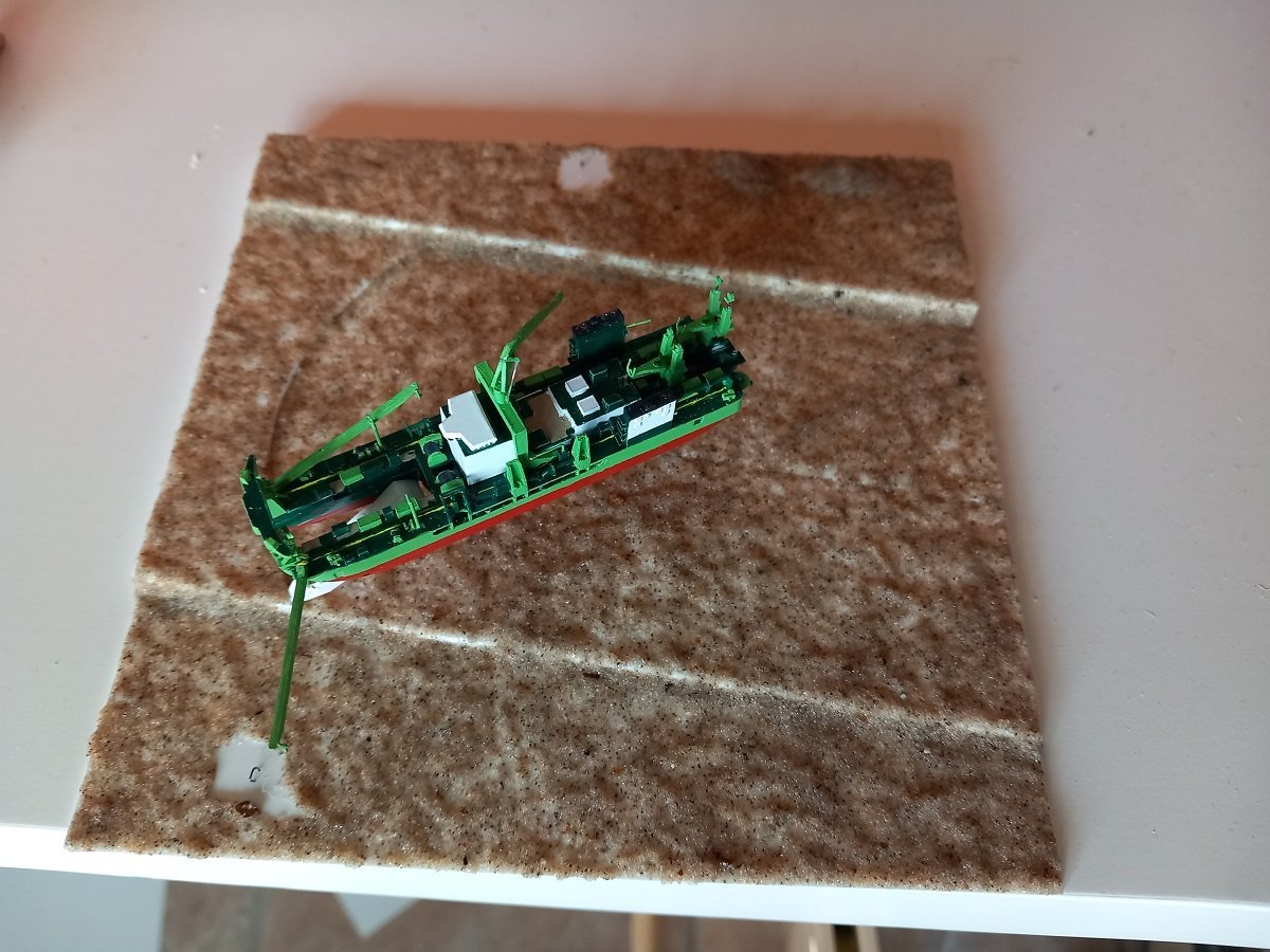
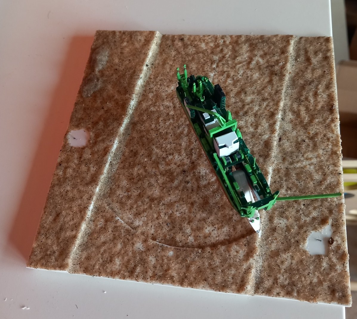
Small steps forward. Started rigging the anchor booms. They're held by a large pendant wire at the top and 2 smaller auxiliary wires. Don't forget that the anchor booms are over 40m (120ft) long and the anchor weight itself is 60t (+ force to pull it out of the ground and additional optional ballast weight). I had tiny 0.3mm holes drilled in the gantry to pass the wires through and similar (but not all the way through) holes in the anchor booms to attach the wires. In the original design I was hoping this would allow me to hinge the boom in to pass the bottle neck and then pull it outwards once inside the bottle. Not entirely sure this was going to work. In any case I have glued the anchor boom in a fixed position on the model now. Will make life easier later on. I've also continued on the base with that 2nd layer. Looking at it now, it does look overscaled, I am planning to cover this with a layer of gel to avoid air bubbles in the epoxy later on. Due to the overscaled look of this sand, I believe I would simply paint sea bottoms in any future 1/2000 scale builds, perhaps with an acrylic base to create more texture. I have also added some different shades of green, although I'm not entirely sure anything would grow at such a depth. It does give a contrast with the original sea bottom and the cut parts in the end. As you can see, she also received the barge loading T-pipes. Considering the top view now, I might adjust the lay-out with the floating line going to PS of the dredger and the multicat approaching on the SB side to balance the whole display a bit.
-
Great solution for getting those halves together, will keep that one in mind for later. Applying that acrylic after the ship is in, will be terribly difficult with that mast and those oars in place. On the other hand it would be difficult to insert and assemble the hull while the gel is still wet... Perhaps apply the gel in the back of the bottle and a bit on the sides leaving a large spot open in the centre for the ship? Then let it dry, insert the ship and add acrylic around it? Just thinking out loud. Didn't apply acrylic to my Sea Installer because of the difficulty to go around objects and smearing it on the vessel. I'll be happy to see your solution.
- 290 replies
-
- 5
-
-
- Quinquereme
- Finished
- (and 1 more)
-
I was just wondering though, you poured the resin, but didn't put the ship in? Does that mean you'll pour another layer or will you insert it with acrylic gel on top of the epoxy due to its limited draft?
- 290 replies
-
- 3
-
-
- Quinquereme
- Finished
- (and 1 more)
-
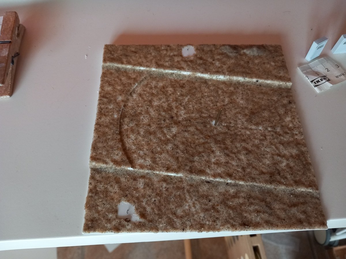
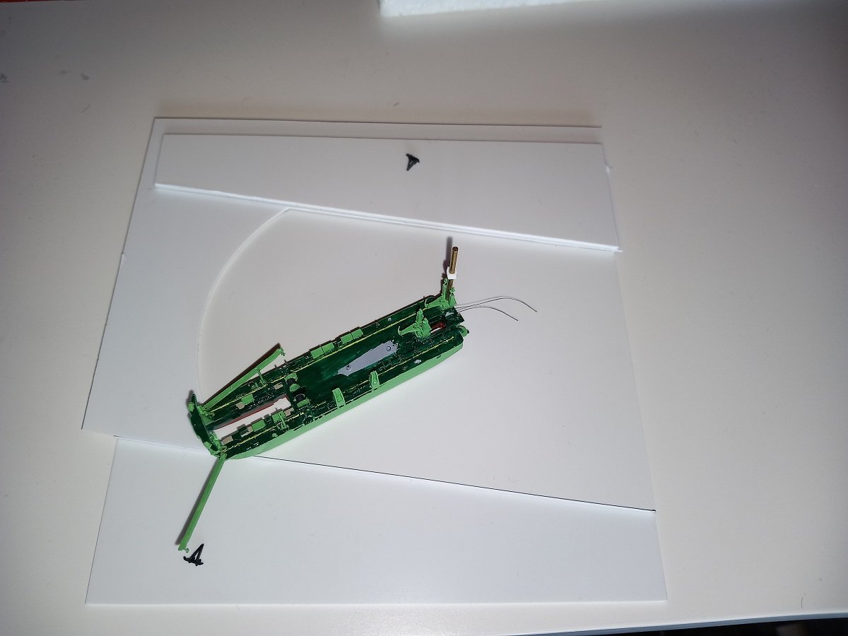
Then it was time to start coating the bottom. First coat. As you can see it was a bit too liquid to stay on the vertical surfaces, but that's not too bad. I also opted not to give the styrene a dark coat. I've thought about it, but I believe it would give an overall darker appearance, obscuring the anchors etc. once it's submerged in epoxy. Also the sand would probably not stick very well, while now it is bonded directly to the styrene plate. In the right corner you can also see one of my secret measuring tools. The paper Ikea measurement tapes are easy to use as you can bend them and measure between obstacles etc. where straight rulers can't be used. You can see the spaces where the anchors should be. I'm going to "cheat" by rigging the wires to the small steel brackets that are drilled in the plate and later on put the anchors over these brackets. It would be difficult to attach the wires directly to the anchors and create enough tension to keep the wires taut. Test fitting of the ship. After this test, I decided to actually change the position of the PS bracket since the original position is a bit too much forward. Everything fits, so I'll continue with the second layer of sand, this time with more density, less liquid and just filling up spots where the first layer is too thin.
-
I was thinking along the same lines as Keith, but I don't think it will be practical. Outside a bottle perhaps, but sliding the hull halves through a noose (which you can't really hold open) will be very difficult, especially with those oars sticking out. Unfortunately I don't really have a better solution to offer apart from "regular" conical locating pins and pushing the hull halves together by the parts on top of the bow and stern. Perhaps a variation on Keith's idea by putting nooses around the stern, bow top and ram to pull together. Those nooses would probably be easier to loop around when the hull halves are inside the bottle, and they'd leave the oars alone.
- 290 replies
-
- 4
-
-
- Quinquereme
- Finished
- (and 1 more)
-
Genious way of doing those rivets. Love the plating effect so far. This is real scratchbuilding.
-
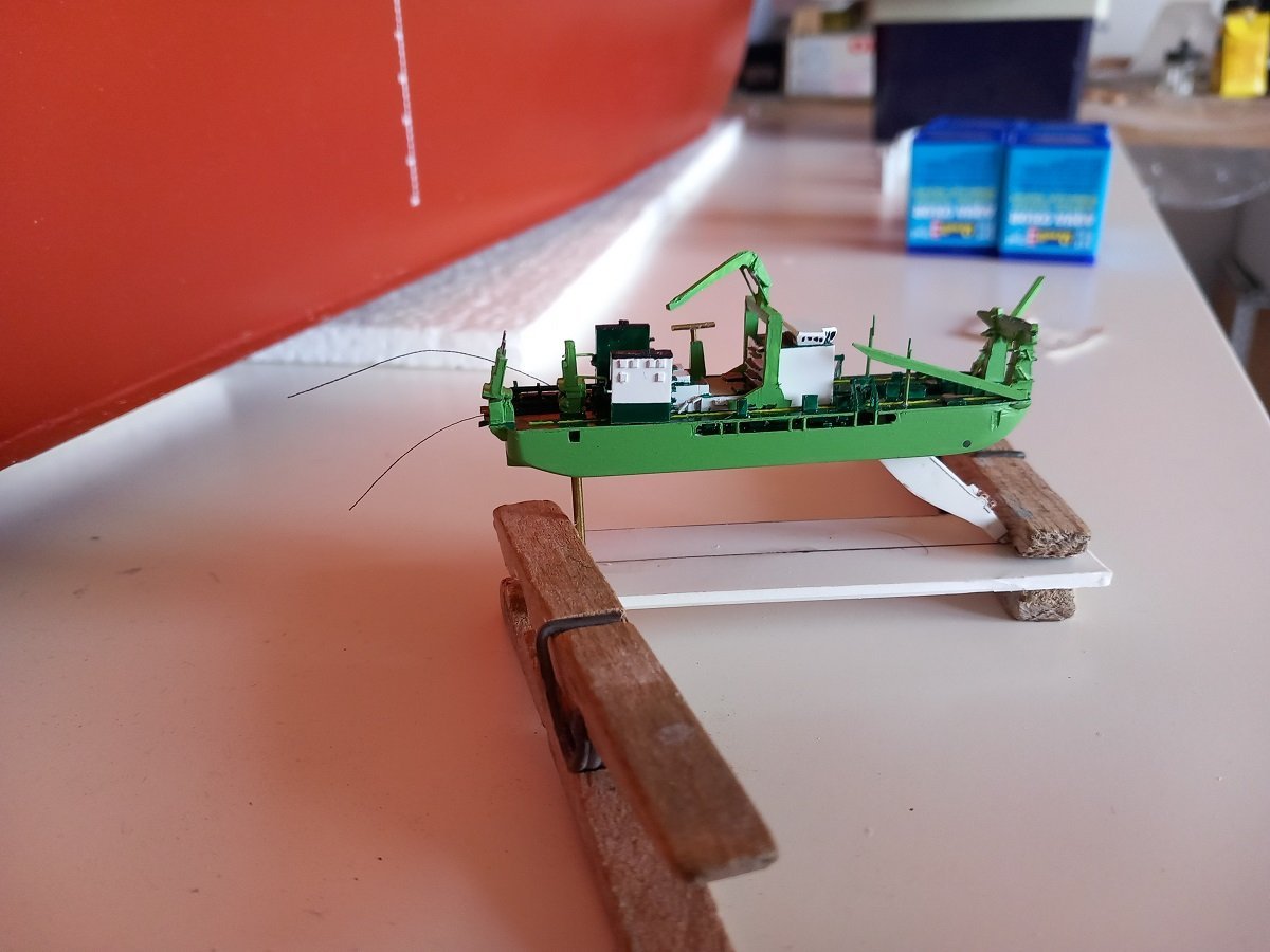
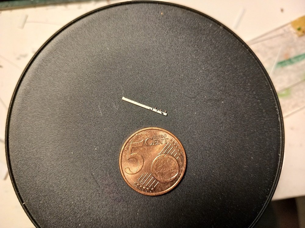
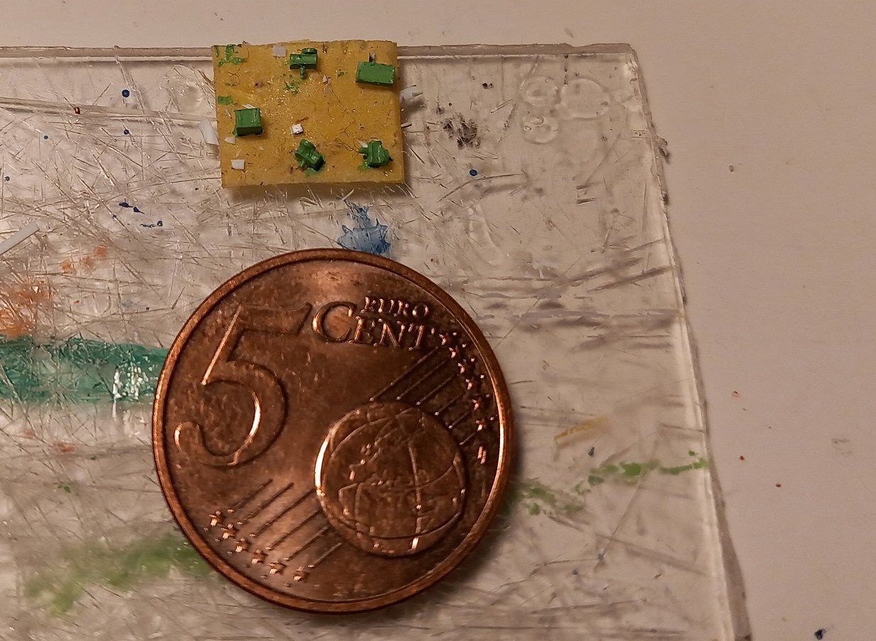
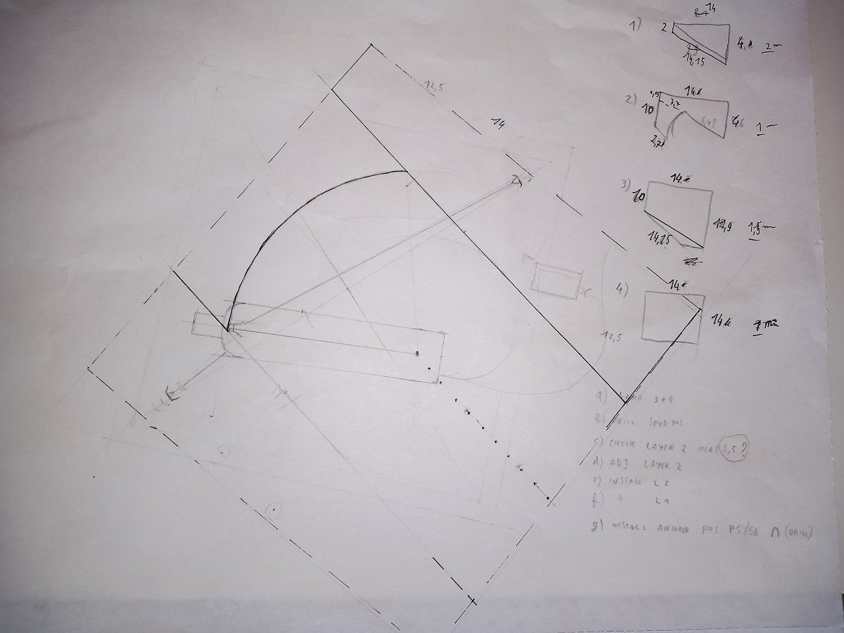
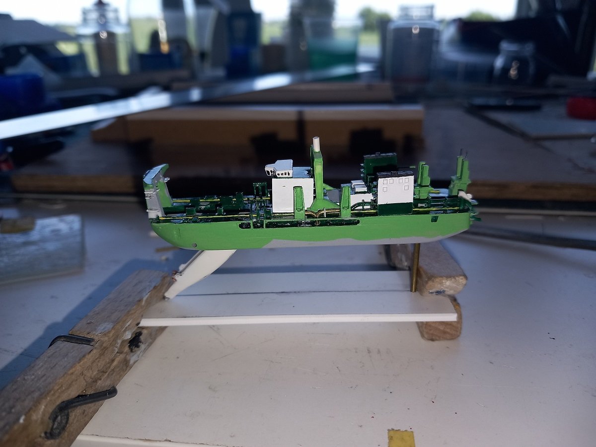
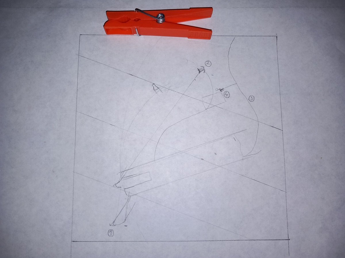
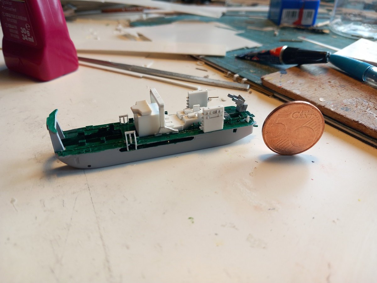
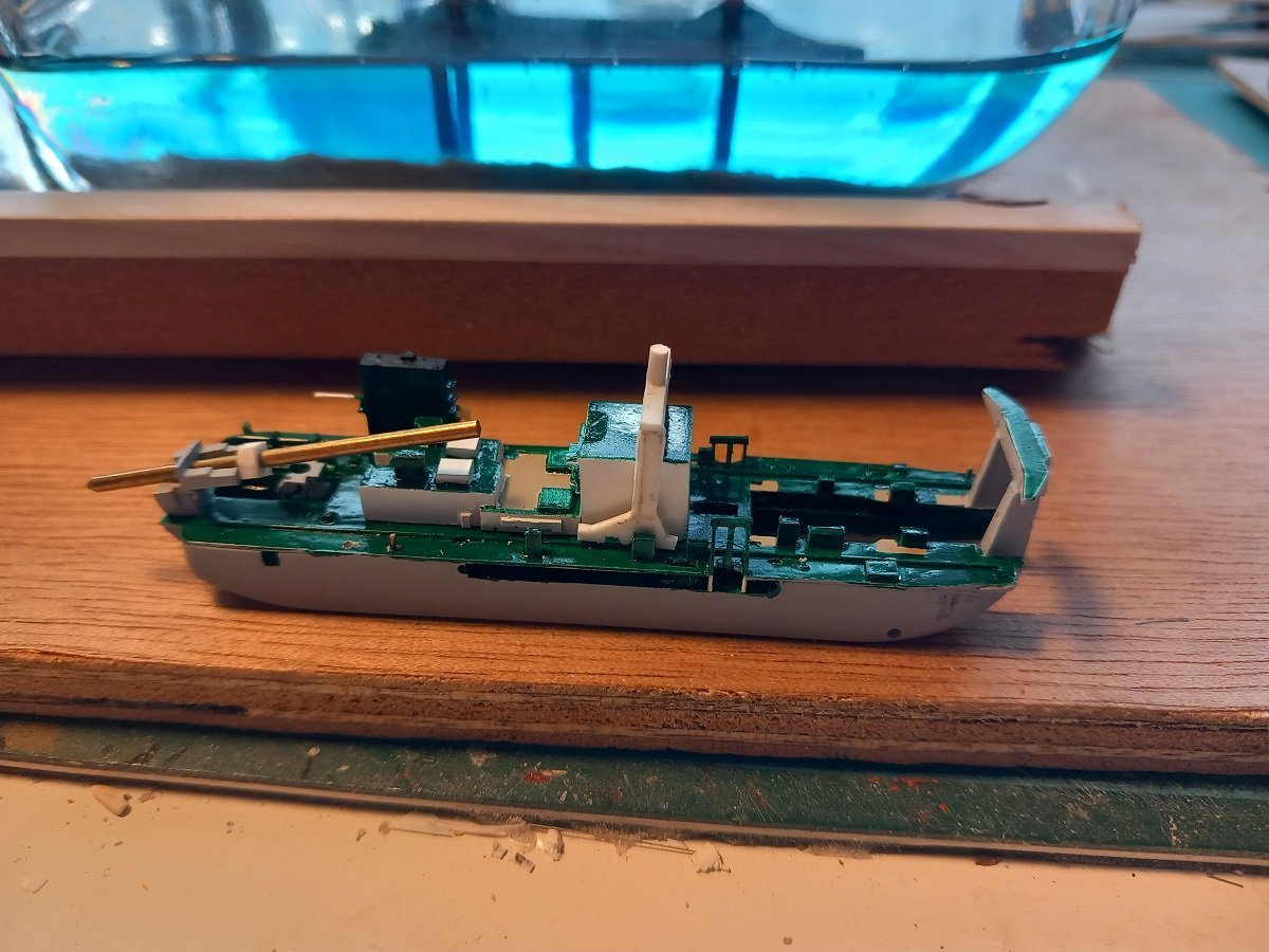
Been a while again. I had expected for a break, but due to unforeseen circumstances, I could continue the build. I've been detailing the ship further, I'm feeling without the bottling risk, I could expend the additional time on this. I've done some tiny rigging on the system that holds the spud and compensates the forces on the spud and vessel in large swell and/or forces from the cutting process. I've made some anchor winches as she doesn't have real mooring winches. Drilled tiny holes in a 0.75mm thick strip. Then cut to length and added the gipsy wheels for the anchor chains. The finished product, hugely enlarged. The other objects are a half-height container and a 10ft container. Fully coated the hull in yellow-green now, to avoid contrasts below the water line when painting the anti-fouling. I then continued with the bottom profile. A more detailed sketch was made. It was then divided in different layers with different thicknesses, based on real dredging operations. The original depth would be the highest point, that part I will probably litter with tyres, debris etc.. The lowest part would be a part that is already at the final depth. The middle part is slowly being dredged in layers to reach that final depth. I chose this lay-out so the deepest part would give a proper visibility on the anchor and dredging cut, while showing some specific issues with having the anchors in deeper and shallower water than the ladder itself. This can give some issues with the wires below the surface. As you can see, I started with the vessel outline and anchor positions. I then chose an orientation and measurements and last, but not least drew the layers and measured them from the sketch. In the lower right corner I've made a small sequence note as I'd probably screw up if I didn't write these things down. This whole profile will be covered and smoothed out with sand-acrylic mixture. The "dredge layer" with the semi-circle, is made too large, so I can adjust to push the ladder back and hold the vessel evenkeel on the spud. The anchor boom will be swept more aft eventually. You can also see the large hydraulic mechanisms to tilt the spuds from horizontal to vertical and vice-versa when shifting between sailing and dredging. Most parts are still dry-fitted since I'm still adding the details. Having the big parts loose leaves me more space to manoeuver the pincers in.
-
Love the blue garden dragon. The ship is also nice Brilliant job so far. In a way it's a pitty you won't do the rigging, but on the other side it does put more focus on your brilliant hull work and decoration.
-
Somehow she looks large... Bulky is probably a better word for it (might be the macro picture of course). It'll be a challenge to get her in a bottle for sure... Great looking corvus, always thought they were shorter compared to the vessel. You're off to a well deserved vacation. Enjoy!
- 290 replies
-
- 4
-
-
-
- Quinquereme
- Finished
- (and 1 more)
-
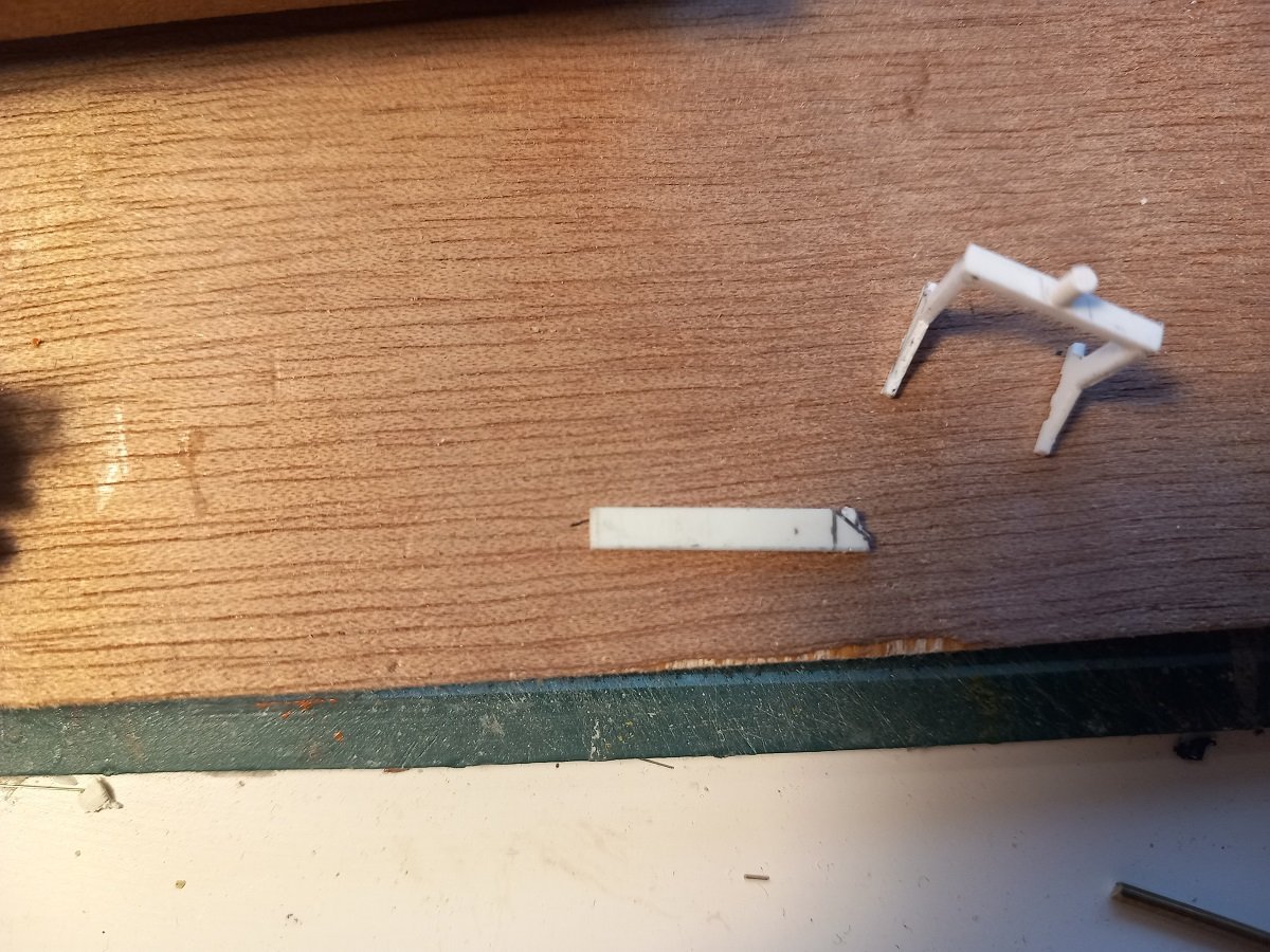
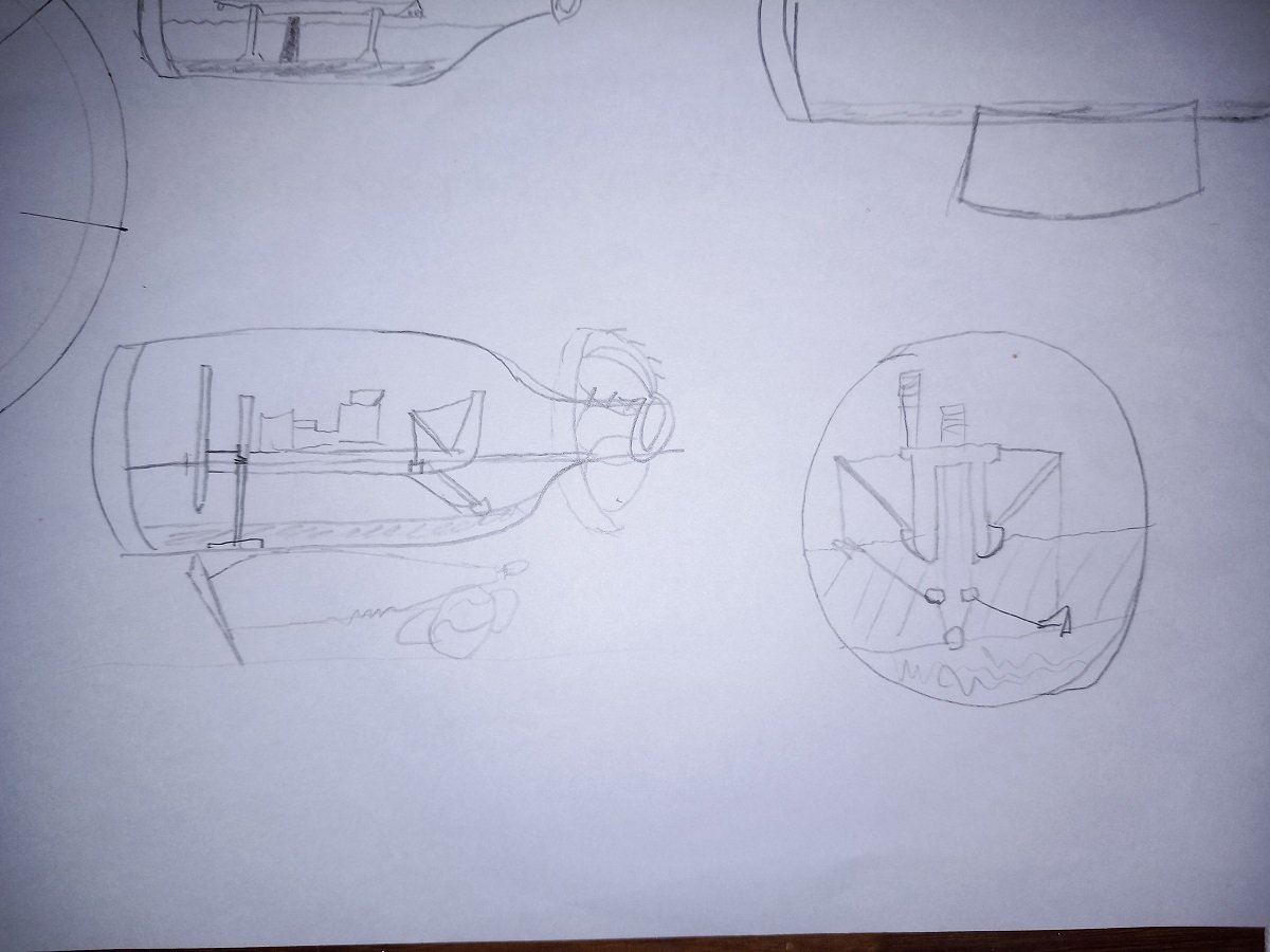
Thanks for the encouragement throughout the project Keith. Let me start off with an example of my production of small parts. In this case I needed to make 4 devices that were of the same dimensions. In such a case I'll determine which measurement is the most important one to be the same and which one I can adapt later on to make them match. Then I'll cut a strip of the most important dimension and start shaping the first part. Once it's ready, I cut it off and do the next one. And time for an overview of where I'm at at the moment. As you can see the barge loading installation is nearly in place. The large T-shaped pipes still need to be placed. It took me a while to realize that by cancelling the whole bottle idea (sorry @Glen McGuire), I wasn't restricted by that bottle anymore. Here was a drawing of the original idea, side view and forward view (from the bottle neck). The cutter head over the neck would have been cancelled considering the experience with the windmill hub on the Sea Installer project, but the bottle was to lay on a dredge anchor supported by some rocks. As you can see on the front view, the rigging would have been a nightmare and doing it ahead of pouring resin probably was a recipe for disaster. Since I realized this, I've gone back to an old concept for this vessel. Originally I wanted to do this in 1/400 scale without epoxy, but with a regular plexi box (which was probably going to take around 3 years to build). Below is a top view drawing in more or less actual measurements. I'll make a more precise one once I figure out what I'm going to use a base for this. Above is a top view. The ship's position you can figure out. Numbers 1 and 2 are the anchors, with number 1 anchor just being laid on the bottom. Number 3 is the floating line (on the surface of the expoxy). Number 4 is a multicat workboat stand-by near the anchor of the floating line. The multicat is there to simply fill up some open surface. I think I'll also treat the epoxy surface with acrylic gel for tiny waves. The straight lines crossing are the "cut" with the middle one being the center line, where the spud is positioned. That would be the lowest part, with Number 2 anchor on a more shallow area and perhaps for visibility, Number 1 anchor on the same depth or deeper than the cut depth.
-
Looks very convincing already! Can't tell if it's card or wood, which means you're doing an excellent job.
-
I don't like a shelf-of-doom. These things tend to annoy me greatly, being a brake on every project, I don't like to leave loose ends. As it stands, I'm now planning to keep the same lay-out, minus the bottle. I think I'll build up a box of 4 plexi walls, build the model inside, including pouring the epoxi to finally finish it by closing the plexi box on top. This would allow me greater access to the rigging during/after pouring, which would increase chances of succes. The anchor boom and its rigging are my greatest worries for bottling as its deployment should be done before pouring (= ship not very fixed yet). Tightening some of the lines and preventing the anchors to float in the epoxy were other concerns/risks. All those things can be fixed in an open box, but working around the corner inside a bottle is doubtfull at best.
-
I'd probably bend some 0.3mm copper or stainless wire around a rod/drill bit of appropriate diameter for the bow and cut to length. Then insert it through or glue it at the end of a small strip and make a support of an opposite V shape of 0.1 or 0.3mm wire. Something along those lines in any case.
- 290 replies
-
- 4
-
-
- Quinquereme
- Finished
- (and 1 more)
-
Well not entirely true. I'm building on autopilot so to speak. Pushing to get ahead with it and get rid of it. I'm on the verge of giving up. Perhaps I'll complete it without a bottle, as a gift to my son. It'll probably be that or just squash it under my foot (which is the faster way). I'm longing for something with sails, probably made out of wood too. It's been fighting with project all along.
-
Hi, I have some serious branches of pear and apple trees in my backyard (more or less freshly cut) and would like to know how to prepare it for modelling use. - Do I first de-bark it? - Do I dry it first (in original branch form or cut up in shorter lengths?) - Do I just cut it in slices and let it dry that way? Removing bark after drying? - Any known sequence/additional info is welcome It's the first time I've cut larger branches and I don't want to let them go to waste.
-
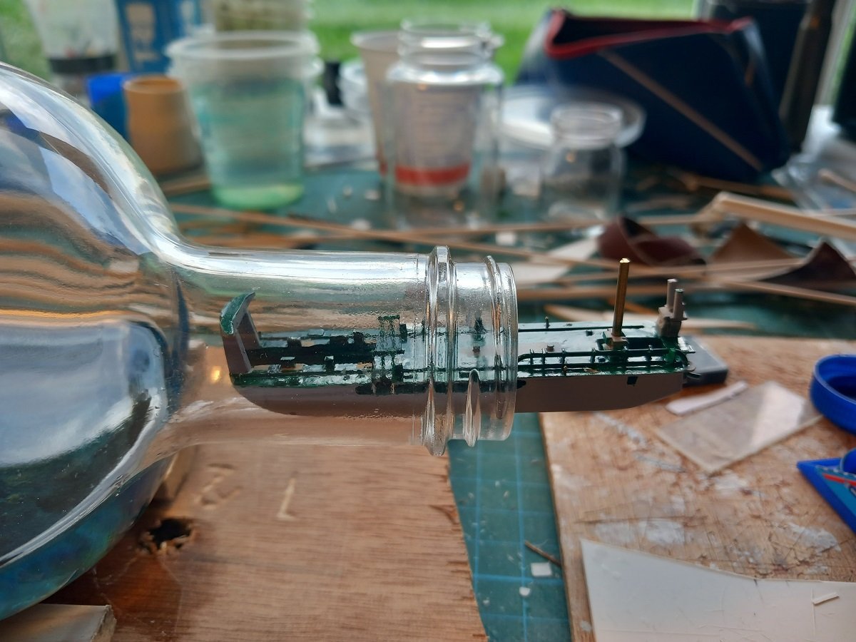
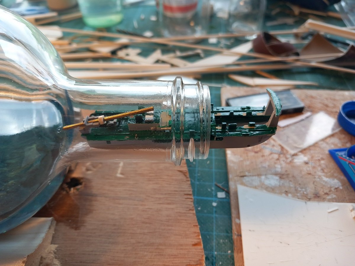
I've made a start on that crane. Seems simple enough, but it doesn't fit through the neck due to its large square shape. The idea is to drill two holes through its feet and mount it on pins to the aft superstructure. The aft superstructure will be glued in place before bottling. The crane will then be hinged down forward, on deck to pass through the neck. Once in, I'll have to erect the crane before putting the accomodation block in place (hope this makes sense). She'll be mounted more aft than on this picture as she's normally somewhere aft to avoid blocking the sight from the bridge when handling the anchors. Since I've been working with simply a circle cut-out from a page to see if things are passing, I though I'd use the Sea Installer bottle for some testing. To avoid surprises later on. I was happy to see the gantry fit through. I'll have to shorten the main spud a bit, but that's not an issue since it's always a question how deep the spud goes in the soil, so I have a few mm (meters in reality) to play with.
-
Great progress indeed. Did you consider an offset cut to keep the bow, stern and masts fixed on one half? Would make life a lot easier I believe. Or is the bottle neck really too tight to do that with the oars and all? I kind of expected my comment to backfire in following way: "Shouldn't you be building instead of making stupid comments in my build log" But I'm happy it's motivating (forcing ) you to carry on
- 290 replies
-
- 5
-
-

-
- Quinquereme
- Finished
- (and 1 more)
-
Cap San Diego by mikegr - 1/160
Javelin replied to mikegr's topic in - Build logs for subjects built 1901 - Present Day
Nice work. Love that forepeak entry hatch with the attached davit. -
I checked and it appears the current rules for navigation lights were only implemented from 1969, so considering the age of your tug, they wouldn't have been applicable. Can't say anything useful on lights pre-dating that implementation, I assume it was regulated on a national (flag of registry) level.
- 118 replies
-
- 1
-
-
- sanson
- artesania latina
- (and 1 more)
-
That's a stunning result on that sail. Quite a job to do all of them like that. Are you going to repaint the hull as well? The green looks quite authenthic, but its application isn't exactly what I'd call "sharp"... On the other side you are restoring, rather than rebuilding...
-
Beautiful model, one note though, the inside of navigation lights is supposed to be matt black, this is to avoid any sheen that would reflect the light out out of its regulatory angle. I'm not sure however, when this matt black was introduced into the regulations. Towing lights are normally a combination of masthead lights, depending on the tow's length. Basic is 2 masthead lights on top of each other (tow less than 200m in length). The red-white-red means restricted in manoeuvrability (also carried by other vessels)
- 118 replies
-
- 1
-
-
- sanson
- artesania latina
- (and 1 more)

