HOLIDAY DONATION DRIVE - SUPPORT MSW - DO YOUR PART TO KEEP THIS GREAT FORUM GOING! (Only 24 donations so far out of 49,000 members - C'mon guys!)
×


Javelin
-
Posts
624 -
Joined
-
Last visited
Content Type
Profiles
Forums
Gallery
Events
Everything posted by Javelin
-
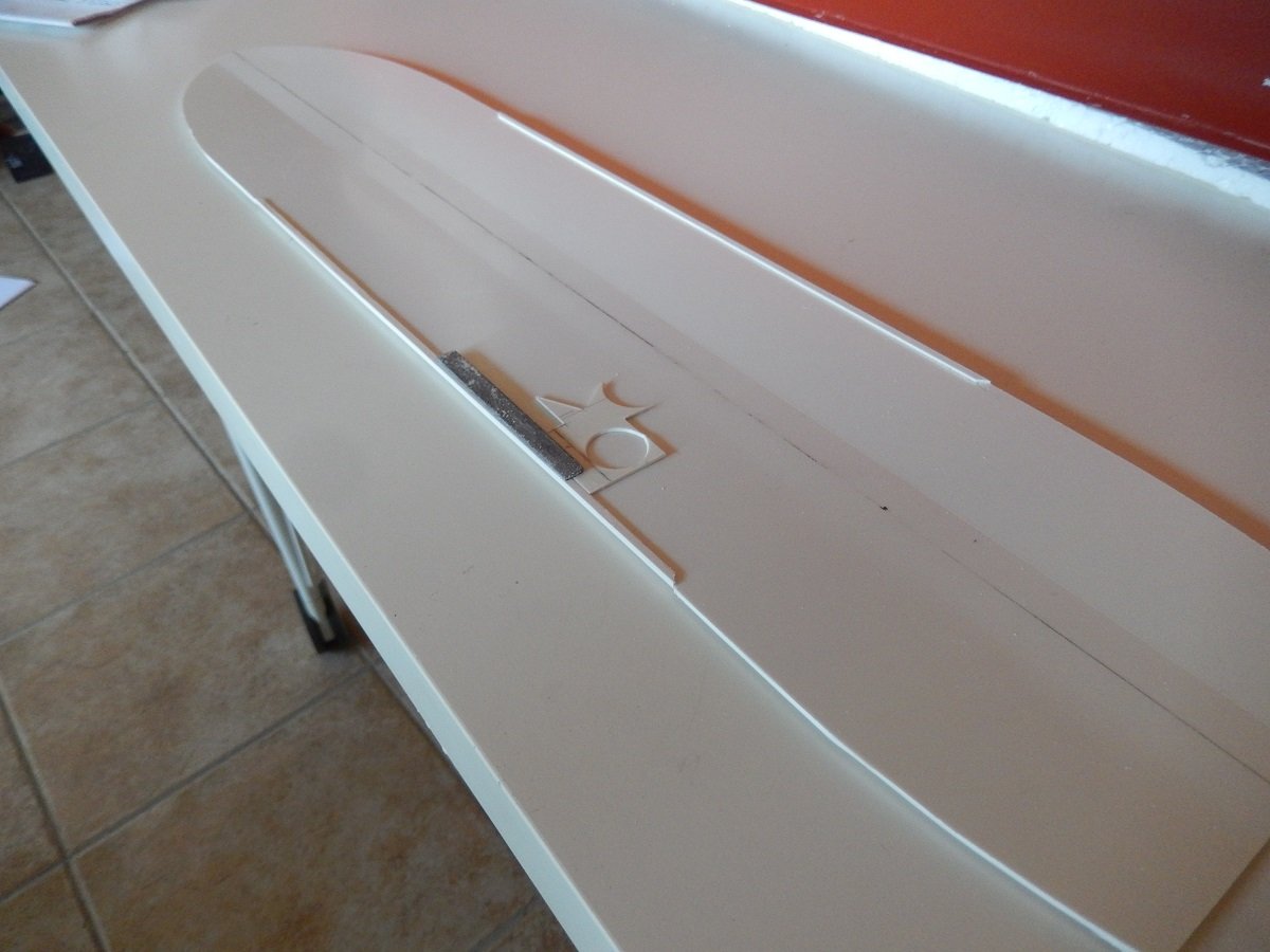
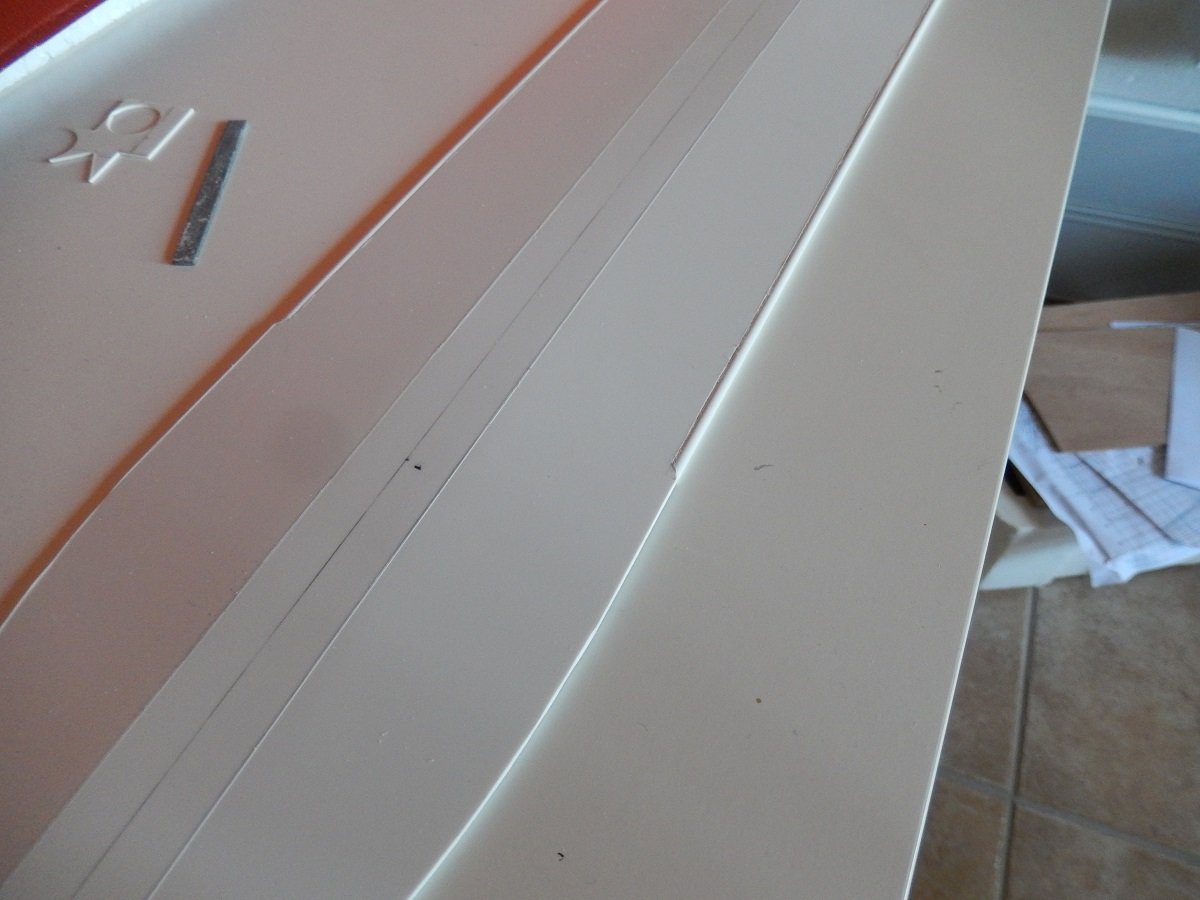
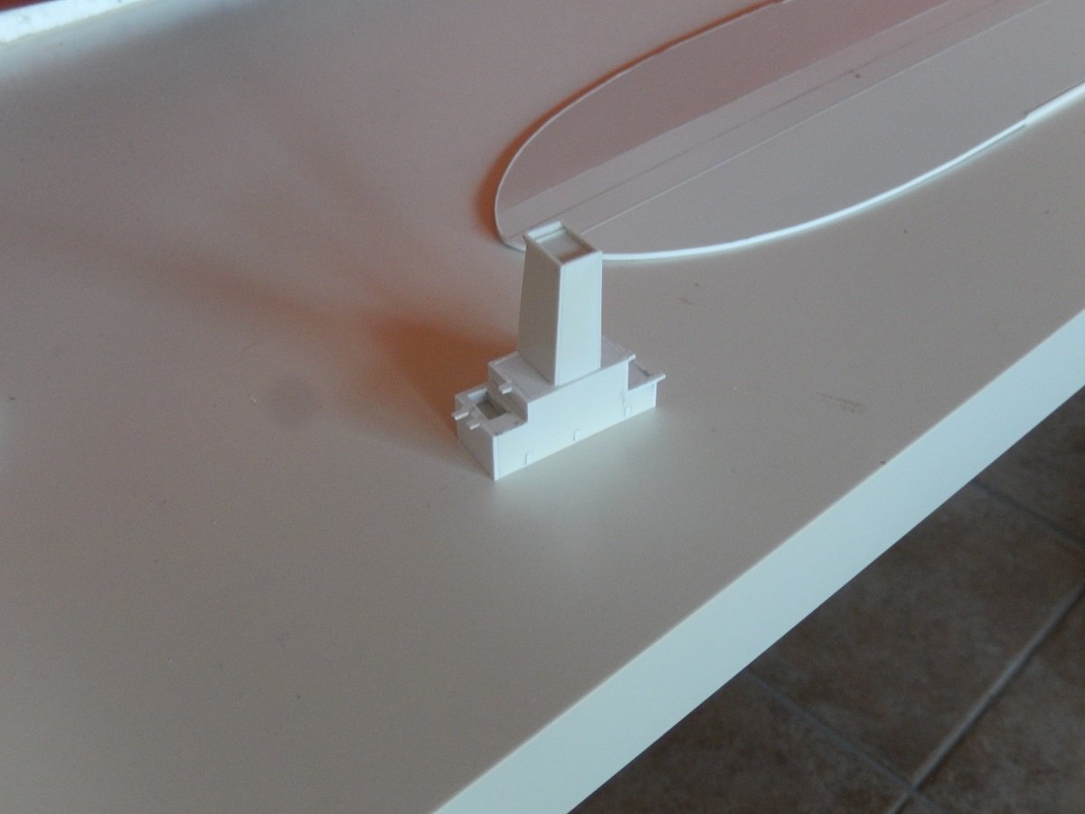
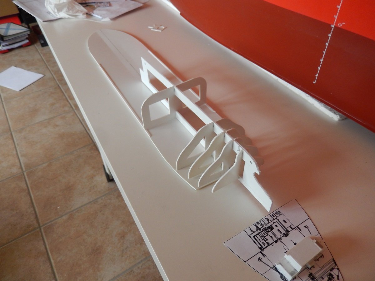
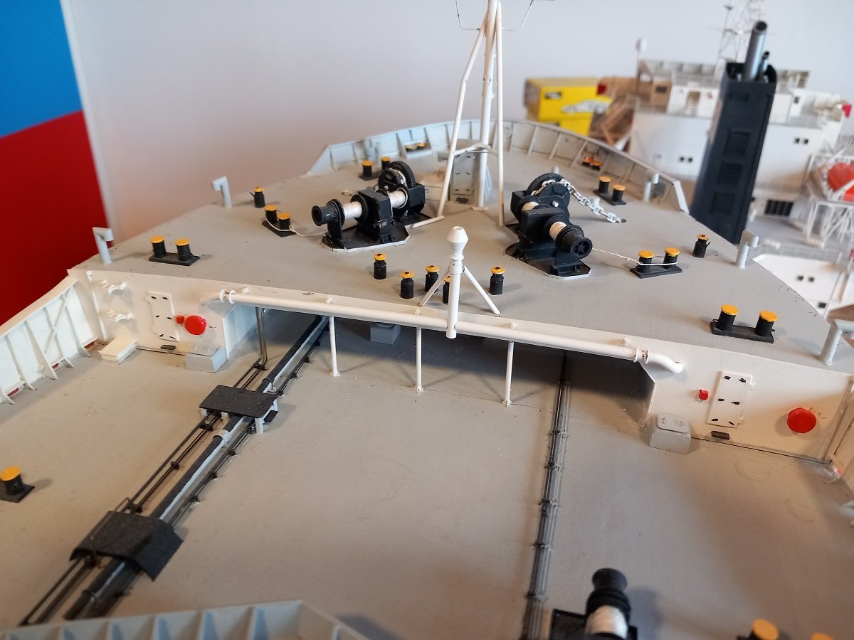
 Well since I'm longer onboard, without the possibility to show new progress. I'd thought I'd fuel @KeithAug newfound love for complex piping a bit further. I consider this build, for an unknown reason, still as one of my best builds. It's an eye catcher in my display closet, probably by its color and size. As the title says, I'm talking about the TI Europe (TI standing for Tankers International, an oil tanker company pool). The TI Europe is an Ultra Large Crude Carrier, one of 4 sister ships built by the Korean Daewoo yard. They were built for the Greek company called Hellespont, but were sold after a few years to the larger company called Euronav and renamed as TI Africa, TI Asia, TI Europe and TI Oceania. TI America was deliberately left out for fears of terrorist attacks since this all happened in the beginning 2000's. When built they were the largest double hulled ULCC's in the world and still are some of the heaviest ships around. Their size, 380m (1247ft) long on 68m (223ft) wide, was huge for those days (nowadays however this is not such an exception with many container ships measuring around 400m long x 56m wide), however their full load draft of around 24.5-25.5m (80-85ft) made them huge. With that full load draft they were unable to pass Singapore Strait, the English Channel etc. in a safe way. Due to that size, they were also restricted in amount of ports that they could enter. These vessels weigh about the same as 5 US Carriers together when fully loaded. When I went onboard, we were doing Ship-to-ship transfers off the coast of Los Angeles to smaller vessels. The voyage then went to Saudi Arabia, where loading happened on buoys connected to the actual terminal by submerged pipelines. Other voyages she often did, took her to Europe, discharging part of her cargo in France before transiting the English Channel to go to Rotterdam with the remainder of the cargo. The model. I built her, using the experience I built up with frame on keel methods from plastic. Size and rigidity was the real challenge here. Since that's also an issue in the real design of such vessels, some solutions were given by the original. The main deck of the beast, can easily fit a US CVN on top of that deck. I've made the main deck of 1.5mm styrene, this was still not very rigid over such a length. However, on the real ships, the corners are rounded, this help divide the forces over a larger surface instead of a single angle. A square angle would simply break loose under such forces. To simulate this rounded corner, I cut a piece of styrene rod and glued it flush with the deck. This added to the rigidity of the deck where it was most needed (the central part). Additionally you see the deck is divided in 3 parts, creating a camber like the real ship. On the real thing, that camber is truly large as well. Then I started building up the skeleton structure bellow, using the table surface and deck to keep everything flat. At the same time I started building the (small-ish) superstructures for this vessel. That's it for today. Since I can't get home for a while, I'll continue soon.
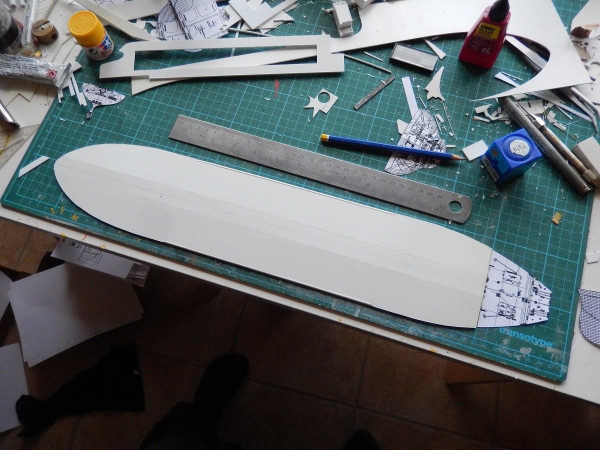
-
Hi Vinoth, are you talking about the real ones or the model ones?
-
Thanks for that Glen. Basically how I made my crude hinges for Sea Installer then. They were far from perfect and luckily hidden by the casings on my model. Also thanks for pointing me to @John Fox III 's build. He cheated by putting "in a lightbulb" instead of bottle and avoided showing up in my bottle searches. That is indeed a work of art, I love his hinges and might have to try and steal that method ( but likely end up on a level of "doing the job" rather than a work of art as you mentioned).
- 109 replies
-
- 5
-

-
- Ghost Ship
- Jenny
- (and 2 more)
-
Great attention to detail again Nils. It is very odd to see a non-studded anchor chain. They are normally studded to avoid knots in the chain. I assume they don't consider that an issue with this type of vessel and anchor, where that anchor is not regularily hoisted.
- 300 replies
-
- 8
-
-

-
- lightship
- Feuerschiff Elbe 1
- (and 1 more)
-
Your penguin is somewhat out of scale, I dare say. I'm quite curious how you did the mast hinges? Did you make 2 halves, 1 on the top and 1 on the bottom part of the mast or did you sandwich 1 piece of top mast between 2 pieces of the bottom part? Kind of difficult to explain what I'm talking about I guess.... Also, the hinge pin, how do you keep it in place? Difficult to make out in your pictures due to the paint. Looking forward to your method for making the ice in the bottle.
- 109 replies
-
- 4
-
-
- Ghost Ship
- Jenny
- (and 2 more)
-
I was just about to send you a message, enquiring about this one as I had seen it in your signature, without a build log link! It's great since I'm scrolling through your sailing ship builds in search of your techniques for a similar build of mine. How lucky can I get? Looking forward to see the rest of this build!
- 109 replies
-
- 5
-
-
-
- Ghost Ship
- Jenny
- (and 2 more)
-
Very sharp and solid work Nils. An astounding pace of construction as well. I believe not many here can match your building speed.
- 300 replies
-
- 6
-
-
- lightship
- Feuerschiff Elbe 1
- (and 1 more)
-
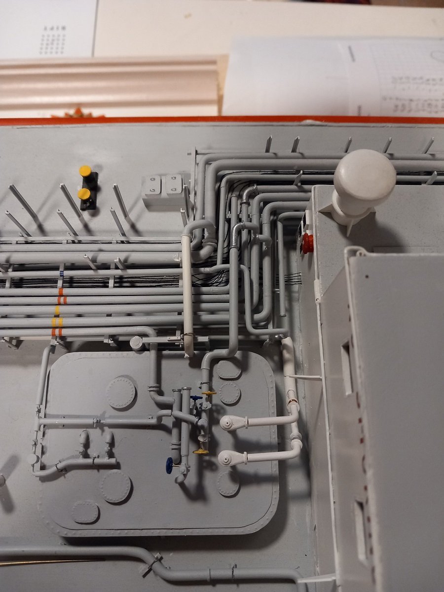
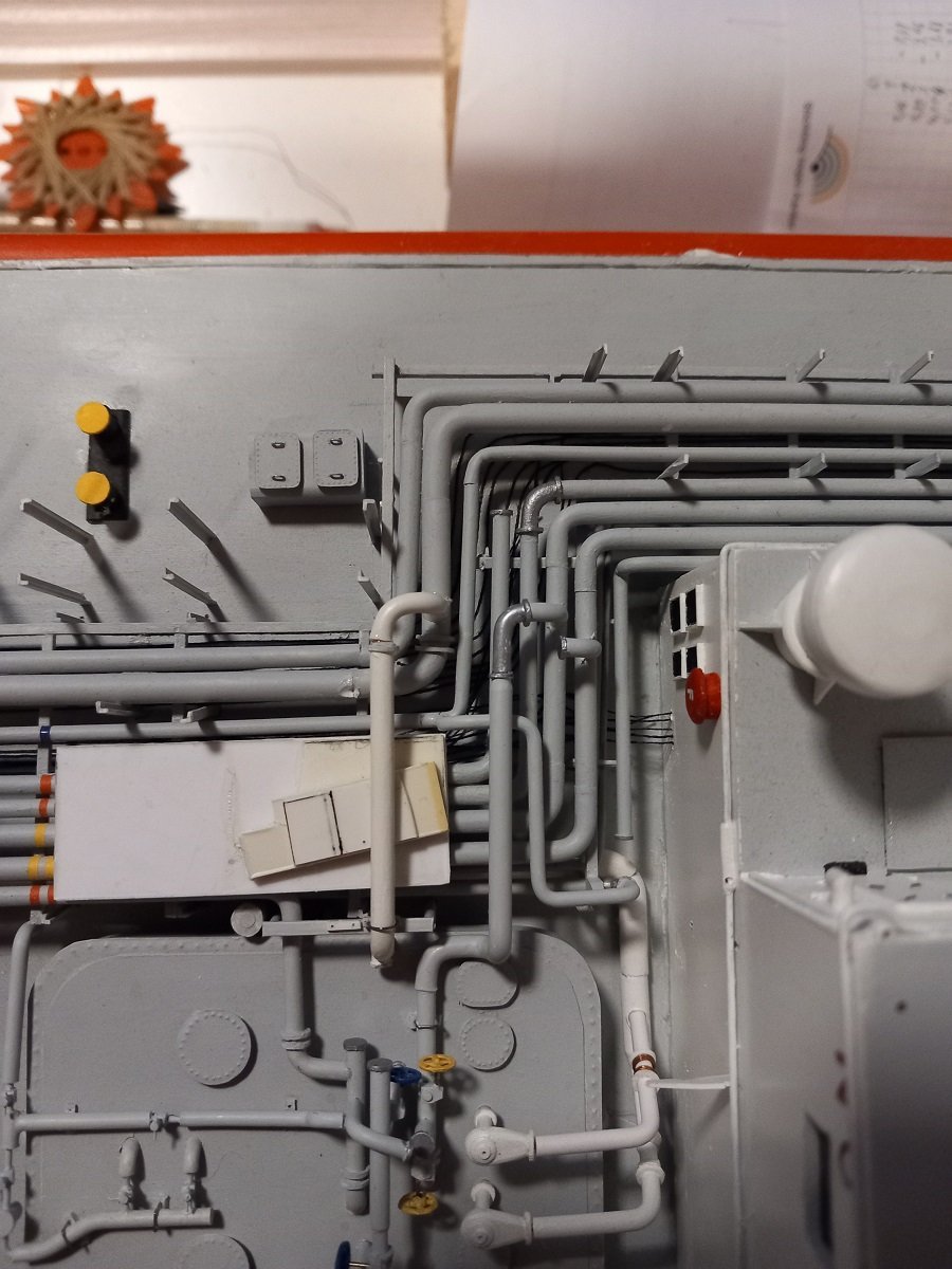
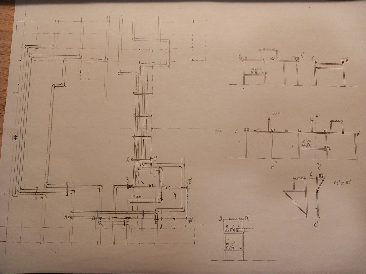
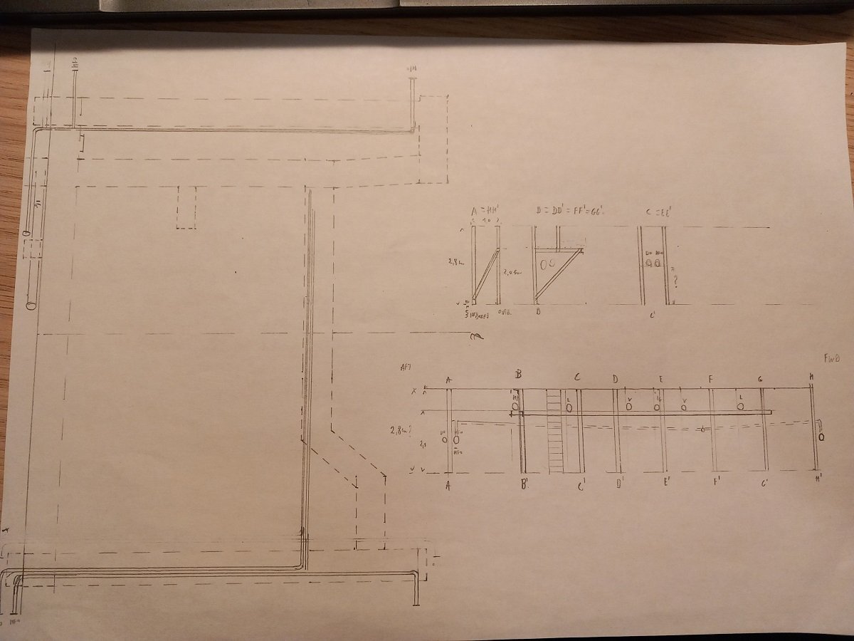
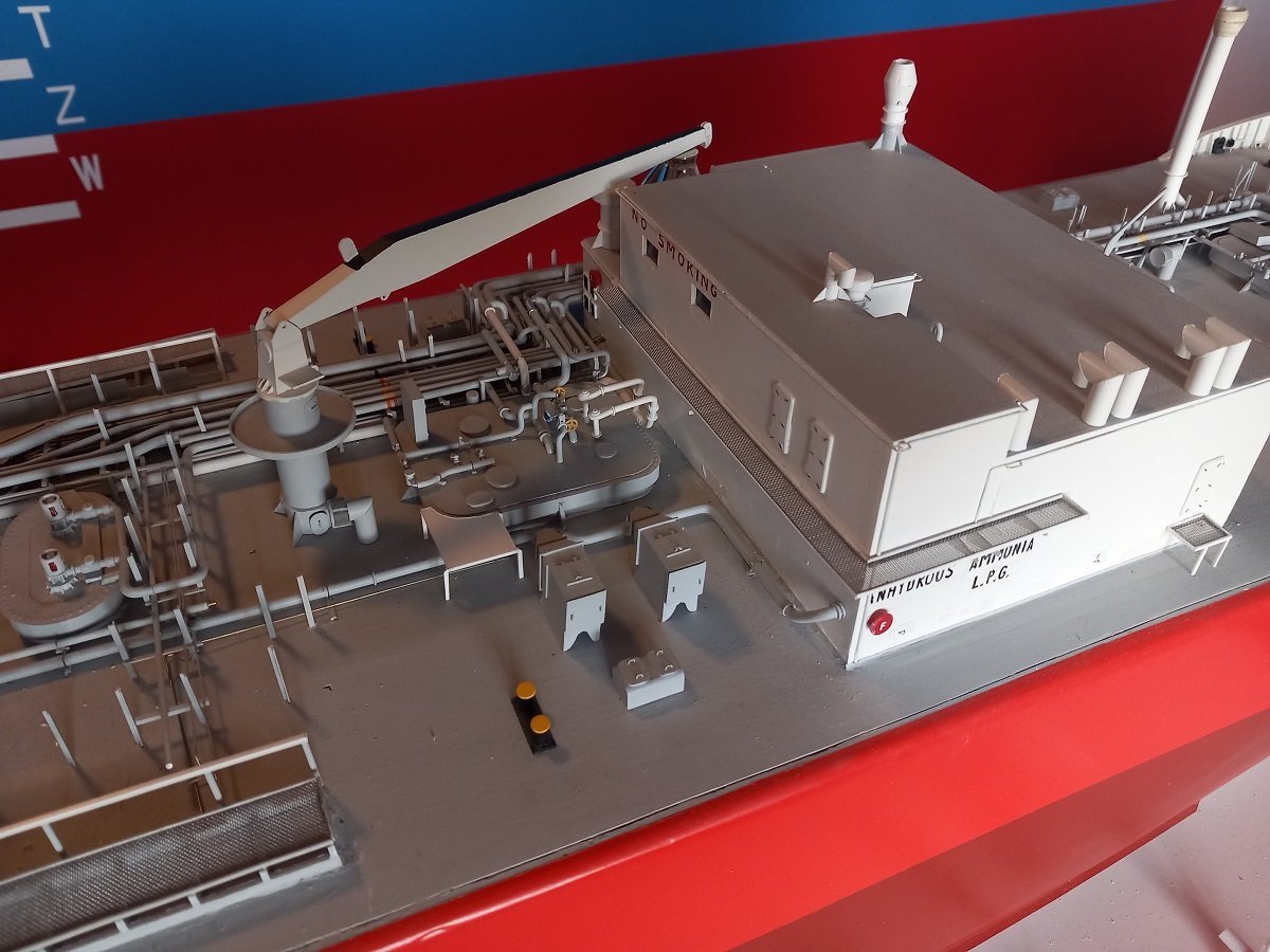
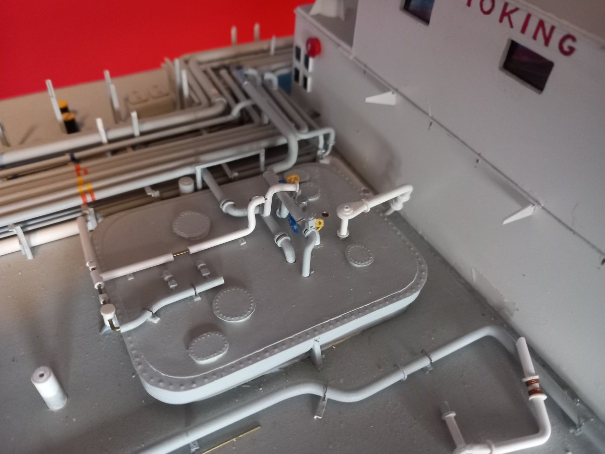
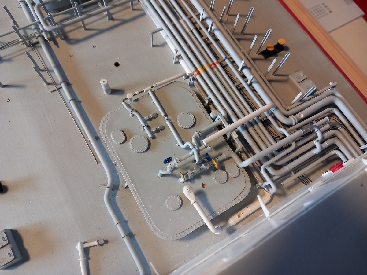
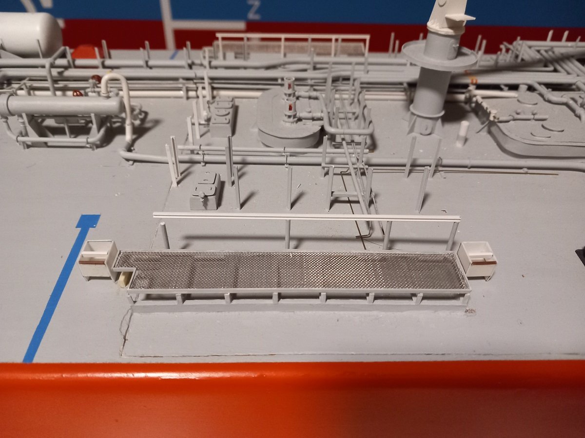
Thanks Nils, This is the (partial) result of the corrections. You can also see in the first image what I meant with the boundary thing on the edge of the hatch. The filler chipped (and will probably continue to do so) at the edge, probably during removal and placement of the hatch (under which the battery and ballast are). If I would have put a vertical styrene plate (sanded flush with the filler) on the hatch and ship edge to contain the filler, this chipping probably wouldn't have happened. I've been thinking about inserting it now, but I guess this might do more harm than good. Sanding it flush and repainting only that edge will be difficult to blend in with 10-year old paint. There is of course also the issue of already placed details on that edge. The I-beam that supports the cargo lines next to the drip tray will also have to be redone. Some clean-up work to do on this side underneath the drip tray. There are some cut remains from the original glued boundary plate on the deck. Currently I'm building up a view of all the support structures in the manifold area. I'm looking at pictures from a lot of different angles to figure out how these structures are made. Unlike today, where things are rather uniform, it seems these supports were somewhat improvised around the piping. This is one of these typical things where you can spend hours figuring out what to build, to be called away to do something else and having to restart the next day... That's why I'm making these plans now. No doubt I'll still have to look at some pictures to verify things, but at least I have an idea of the way ahead when I restart building. The left part is actually a blank version of the walkway on top of the manifold area taken from of the ship's plans, which I then copied several times and where I can then add different layers of piping and supports without remeasuring all the time. It also helps me to verify some distances with comparisons of other equipment.
-
Interesting project. I'm quite curious how you will finish that hull and keep it water tight. I've checked the ship and saw she has a single propellor, so the shaft will have to pass through the keel. Hope you took that in account from the start. Good luck and I hope to see some update on that hull soon.
- 11 replies
-
- 1
-
-
- Malaspina Straits
- plastic
- (and 1 more)
-
Great to see another build of yours Nils. Always fan of a colourful odd subject, so I'm following this one with great intrest. The finest mesh I've used is a plastic teabag. Not sure if you can stil get those. That could be glued rather than soldered to the platform. Another fine mesh is stainless steel mesh from a splash shield from Ikea. Very cheap, very fine and strong mesh. Of course it would be more difficult to hold in place. Examples of both meshes are shown in my Chaconia build. Looking forward to more progress on this build!
- 300 replies
-
- 7
-
-
- lightship
- Feuerschiff Elbe 1
- (and 1 more)
-
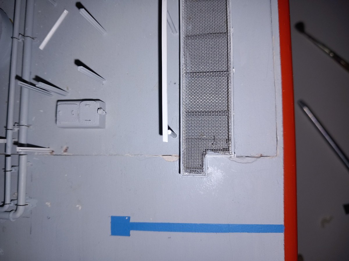
It definately looks very useful, but I live in Belgium, so I guess it might be a bit difficult to order from them. I have however found some online shops for plastics closer to my place, so that's where I'll go shopping very soon. In the meanwhile I've continued with the hose handling crane. Painted it, detailed it further (not yet on this picture). I will however keep it loose untill the equipment around it is finished. I had the idea (at the beginning of this build) of putting a thread bar with nuts through it, so I could use it as a handle to lift the lid from the hull, but I've decided against it. There was little room inside that crane to put a nut and I guess grabbing it, pulling some weight on it, would probably destroy the crane eventually. Apart from this, I've finally started tackling some issues passed on to me by the younger-me. For structural members that can take some hit from the water, I decided to glue it directly to the wood rather than to the filler coat that covers it. However, this means I have to remove some of that filler to insert the pieces. On the manifold drip trays, I made a mistake in that, so now I need to cover some gaps and paint them over. On both sides I made a measuring error, placing the drip trays too much forward. And on the forward edge, those drip trays should have acted as camouflage for the lid seam. The idea was good, the execution on the other hand... Not sure what I was thinking when I thought of fixing the aft boundary of the drip tray on the vessel and the forward and aft boundary to the lid. Apart from that, there is also a small angle that's supposed to be there, but it seems younger-me didn't really think of a solution for that. I have now removed the aft boundary from the vessel, inserted a plate as a doubler to the bottom in order to have the complete drip tray boundary fixed to the lid. Since the grating is on top of that drip tray, the plate will be hardly visible, an acceptable sacrifice to solve this little issue. Still lots of clean-up to do on the vessel, I guess I'll start using my airbrush along with my regular paint brush that I've been using to remove the dust up till now.
-
Recently, during a trip, a stumbled over 2 bronze guns made by Burgerhuys in the Netherlands around 1670's. That made me look around for more info on those and I found a rather interesting file about Dutch guns and in fact guns/cannons in general. It's written in both Dutch and English and contains lots of pictures and drawings of preserved or discovered Dutch guns around the world. The file can be found online, but I has trouble linking it. It's from Cultureel Erfgoed, which means Cultural Heritage from the Netherlands. I've just started reading a couple of days back. Interesting read so far, clarifies also a lot of terms used in cannon/gun subjects. Edit: figured it out. Here is the link as well. Dutch cannon file Kanonnen+van+Nederland+-+Guns+of+the+Netherlandsweb.pdf
-
- 4
-
-
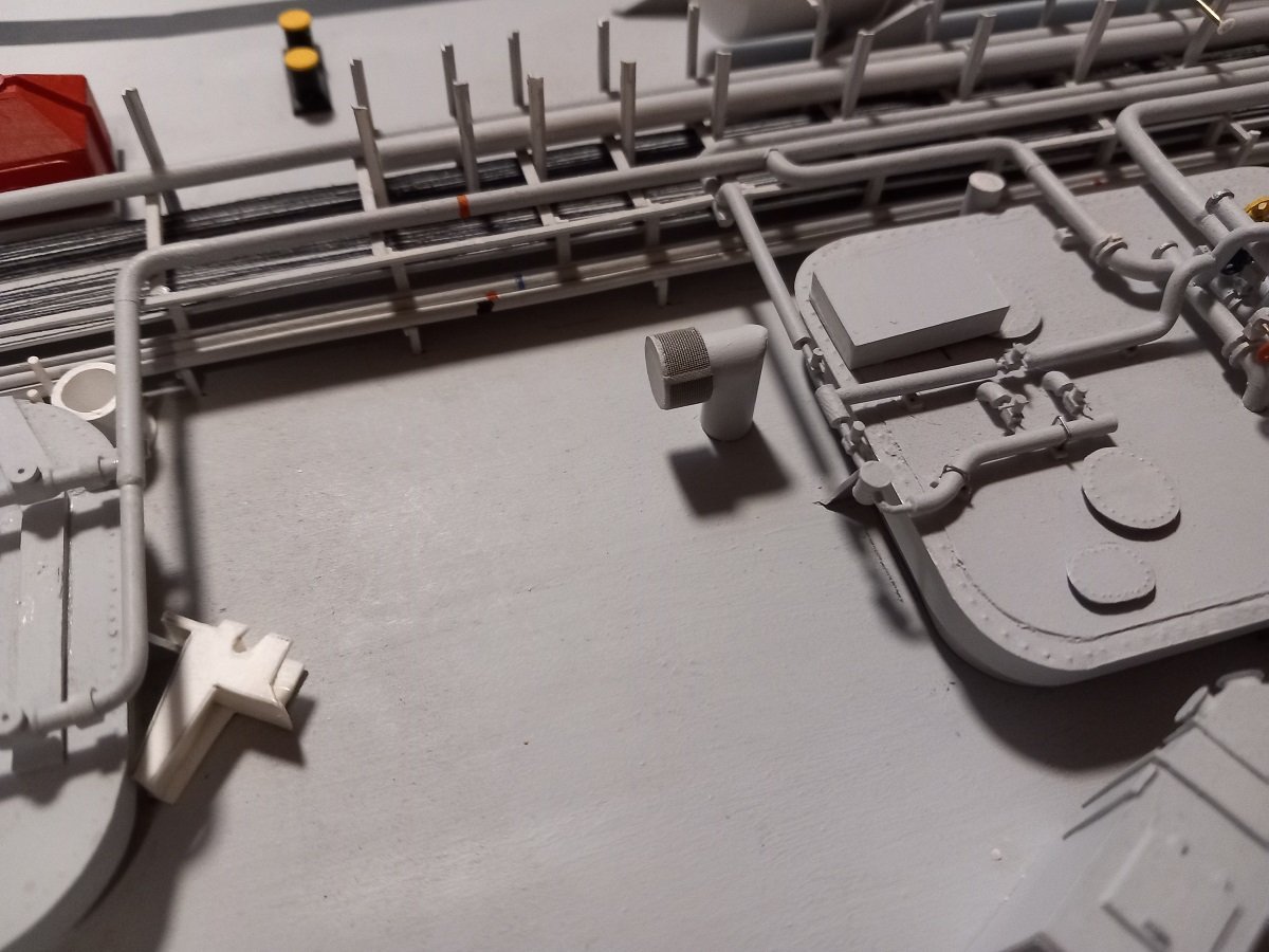
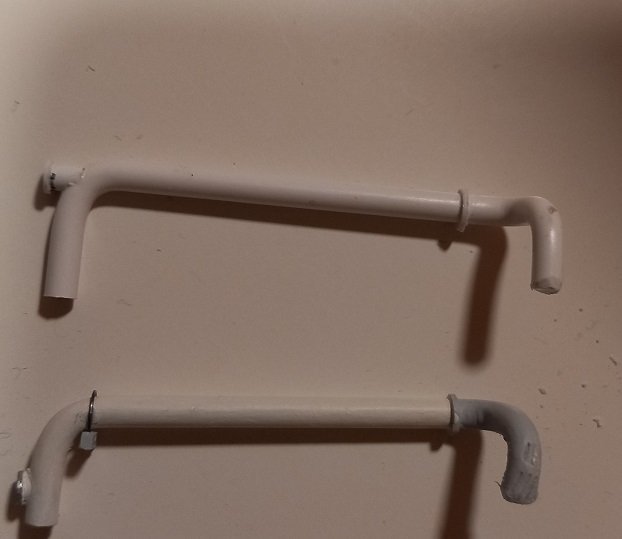
Oh yes, dusting is an issue, although I am thinking of a display case for this one. Probably won't sail with it anymore in that case, or just make a case where I can easily put the vessel in and out (perhaps even through the bottom of the case? ) In any case, when I'm dusting off parts of the vessel where I'm working, it literally has piles of dust on it... Since I need to go to sea again (yes, time to continue my research on that manifold area), I've been doing some small items and projects around the vessel. Somehow I've always avoided the ventilation of forward spaces. It's a pipe with several bends in it, connected to a more or less central vertical ventilation shaft containing the fan. I now built that. The head of the fan was turned on a mini lathe, but I believe the diameter is too small, so I'll probably have to redo that. One of my issues is availability of styrene rods for easy machining. Currently I've had to glue tubes of different diameters to each other, but often the glue is not evenly distributed, causing damage when I'm turning on the edge between the tubes. I guess I'll have to find a source of rods as I'm a bit tired of trying many times to get a single good result. It still needs to be painted. (you can also see the crooked forward mast, this happened in a collision with a bridge, where I lost sight of the vessel. I will still need to fix that some day) Next were the bursting discs of the hold spaces. Each (independent) tank is sitting inside a hold space. This space is normally filled with either inert gas (LPG/flammable cargo) or dry air (ammonia). The pressure in those spaces is above atmospheric and of course subject to change with temperature. In order to protect the ship's structure, there are overpressure (safety) valves on those hold spaces, to release pressure when it gets too high. If, for some reason, the pressure is rising and the safety valves cannot handle the rise, there is a big bursting disc on each space. This disc simply breaks and open the space up to the atmosphere. Since you don't want parts of those discs flying around the deck when that happens, they are mounted in a protective cover that catches any debris. I had built 3 elbows about 10 years ago, finishing 1 completely, and then somehow never completed the remaining 2. Since I had an example, I knew exactly what to do, so they are all ready now. The very fine net around the piece is actually a tea bag. In those days they sold these plastic tea bags, luckily I saved a few, since I don't see those in the shop anymore. They have a very fine, strong netting texture. I also made a platform for tank 2, that will later on be sided by 2 stairs, 1 on each side of the big seawater pipe. It will receive a few more feet, but I first need to complete the piping below before I can finalize that (part of the research).You can also see one of those unfinished bursting disc structures. The platform will eventually be flush with the tank dome. Although I didn't remember the crappy paint job on this vessel, I can see some spots that need some fixing.... A lot of them in fact. Painting, clearly my least favorite part of this hobby.
-
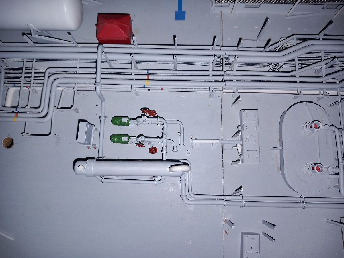
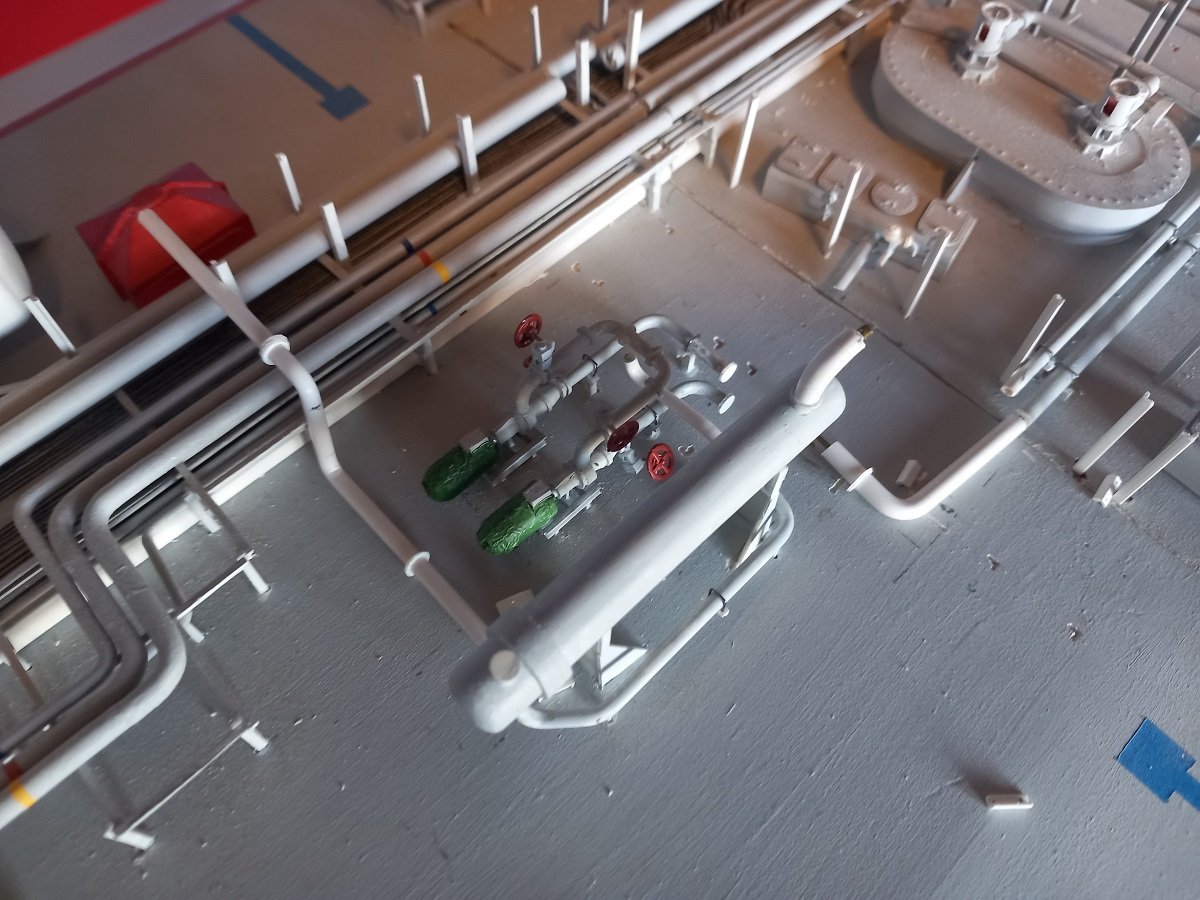
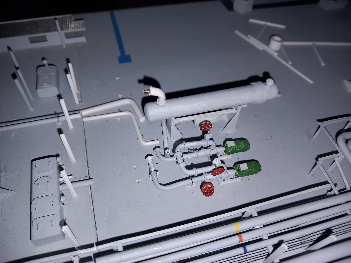
Didn't have the best of days yesterday. The next pipe on the schedule was a cross connection from the IG line towards the cargo tank. The difficulty in these pipes is a double bend of 90°, 1 horizontal, 1 vertical. The vertical one is not truly an issue, but it's the distances that have to be correct. You can adjust the height of the vertical bend, but between the vertical and horizontal 1 it needs to be correct, since you want the end to land where you need it to land. Spend about a day working on 1 pipe, which seemed to fit perfectly. Only in my haste, I made a branch at the top, and that branch had be at the bottom... So started all over again. Of course you can't do such a double bend twice at exactly the same distance... So it was a bit off, but I thought I could correct that by making the horizontal bend more than 90° and adjusting the length of the pipe at tank side. Issue with testing the fit of this pipe is that it wasn't stable. I had difficulty keeping it in place for an overall check and adjustment of measurments. After a day I decided it was ok and I started painting the thing for mounting on the model. This time, the branch was where it should be. At the bottom. The system is in some way quite brilliant. On the IG side, the aft connection is high, the forward one is low. On the tank side, the aft connection is low, the forward connection is high. There are two angled connection pieces that allow either the two low and two high pieces to connect to each other, or form two low-high connections. This allows you to either put gas to the bottom of your tank and evacuate through the top or to insert the gas on the top and evacuate from the bottom by only shifting two spool pieces. In following pics you see the forward IG pipe, 2 days of work (for some odd reason they painted part of that pipe white and not grey...). It looks ok from this side. But not from this side... It was too much of an angle compared to the other transverse pipe, I couldn't live with that, so I eventually tore it off again. So off to a new start. Bending it further was not possible without destroying it, but I still had the old pipe with the better bends. I decided to cut those bends off at the "flange" and mount it on the flange of the faulty pipe. Somehow those bends weren't proper neither. After some playing, I sort of rediscovered my old method, electrical wire. It nearly has the same diameter as the pipe itself and the copper core allows for a lot more adjustment than the styrene pipe. I did also find a way to support the salvaged part of the original pipe, which was cut at the flange, for making the double bend. So now they lined up properly. In the meanwhile I have also mounted the aft connection to the IG line and as you can see in the above pictures, I have completed installation of the manual valve pieces and painting of the condensate line on the aft edge of the dome. With this done, the piping work (apart from fixing and painting of the portside safety valve) on tank 2 is finished.


-
Although I don't really share Keith's opinion about the beauty of these pipes, here is something totally fun for him... (less so for me). All in all I do enjoy this part as well. My 2-parts-per-day target system seems to work as I have made more progress than I had expected. Somehow the remaining work seems less than what I had anticipated. Since the heater bottom level was finished and I need more research for the next level on the manifold, I decided to go for tank dome 2. I had done some work on it before, but left off before finishing. At first it looked like my younger self put my older self in a tight corner there... Untill I discovered most of that piping wasn't glued yet! So you'll see things disappearing in the next pictures, this is just to make more space to work. All in all it was ok to work in that crowded area. The painted pieces are old, the unpainted pipe is something I just made, with flanges for valves prepared, but not glued or filed down yet. Next up was finishing that line on the tank dome and make its connections to the cargo system. As explained, Tank 1 and Tank 3 are on a different system, while Tank 2 can be connected to either of these systems (and the systems can be connected to each other to form 1 system as well). This means that the piping of tank 2 can be shifted by shifting elbow pieces. They had a rather funny system that is used all around the ship, where the elbow pieces have an L-shape, with a long and short leg. By mounting it with either the short part or the long part on the pipe, you connect to a different system. You can see the possible connections in following pics. Next was the connection of the condensate line (return from reliquefaction units) to the tank. I had already made a large part of that system, including the strainer, but not the by-pass line to the liquid line. So off to another run of dry-fit tests and adjustments. Luckily the thicker parts are insulation, while the thin, brass wire parts, are the actual pipe. Valves are mounted on the pipes themselves of course, so the insulation stops a little before and after the valves. From a modellers' perspective, this gives addition points to adjust the length of the piping. The brass wires are also drilled in, so eventually I can also add length by simply not pushing the brass wire all the way into the drilled holes. And the next step was more supports and additional crossing lines from the large diameter Inert Gas line towards the tank dome. Another dry fit. Slowly this tank dome will be finalized, a pretty big step (mentally at least). By using my 2-part-per-day method, I'm also not held back by any research (for now). If I finish something, like this tank dome, I still have a lot of individual items to make, so even if I'm somewhat stuck in the order of things, I can still make items that will be placed later on. I need to make them after all and for the time being, progress is progress! Although you don't really see it, I'm drilling most parts inside the deck for fitting. This gives additional strength apart from the glue. Although I haven't had any water over the deck yet, I also haven't sailed at full draft and I don't want half of the detailing disappearing after one accidental wash (one never knows).
-
Sad to hear this Keith. You (and yours) are in my thoughts. Your build can definately wait until Maggie is fully recovered. On the brighter side I'm happy to see she "got away with it" relatively lightly, if I'm allowed to say so.
-
Since I love colourful ships, you can count me in. Never really seen a model of a lightship being constructed from scratch, should be interesting!
- 300 replies
-
- 6
-
-
- lightship
- Feuerschiff Elbe 1
- (and 1 more)
-
Fantastic work Glen. Your plants are out of scale, 2-3 sq ft leaves? But I know you don't mind and it doesn't bother me either! Great work on those waterfalls, if there's 1 ghing you won't be improving anytime soon, it's those... Because you can't improve those, they're perfect, colour, opaqueness and topped off by those cotton splashes. Didn't notice before, but I love that splash where the water enters the "sea" inside the bottle!
- 174 replies
-
- 4
-
-
- Waa Kaulua
- bottle
- (and 1 more)
-
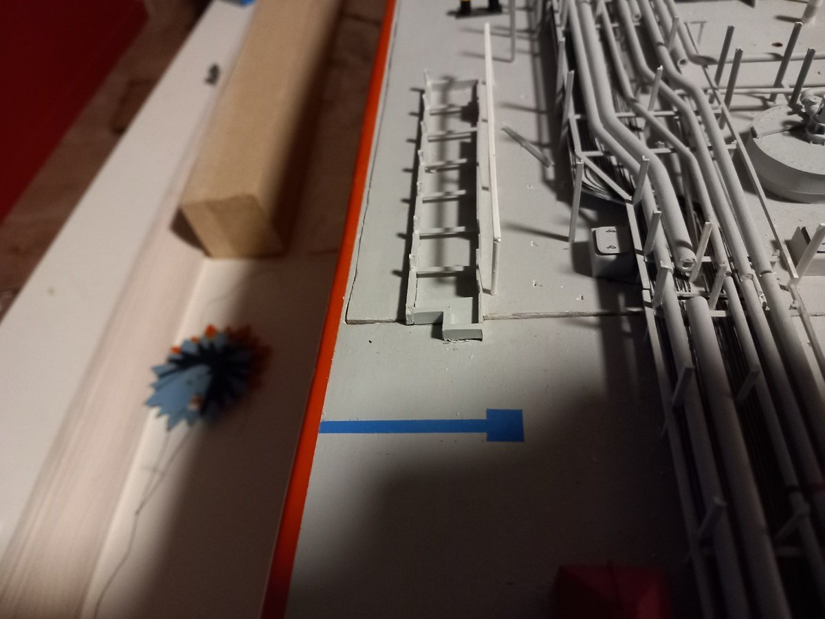
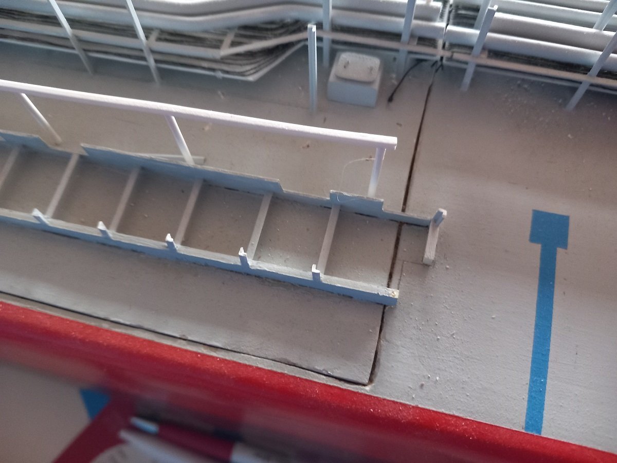
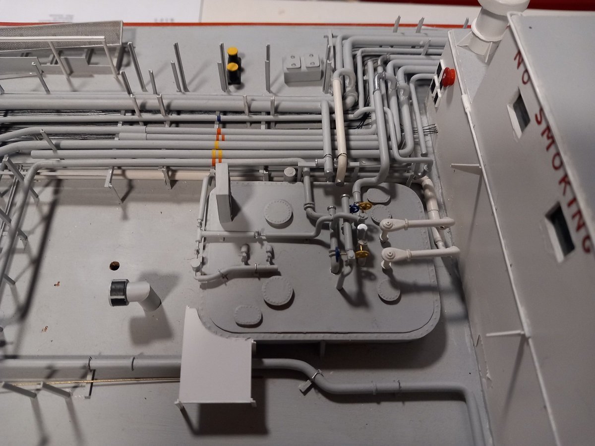
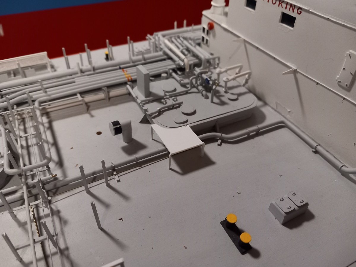
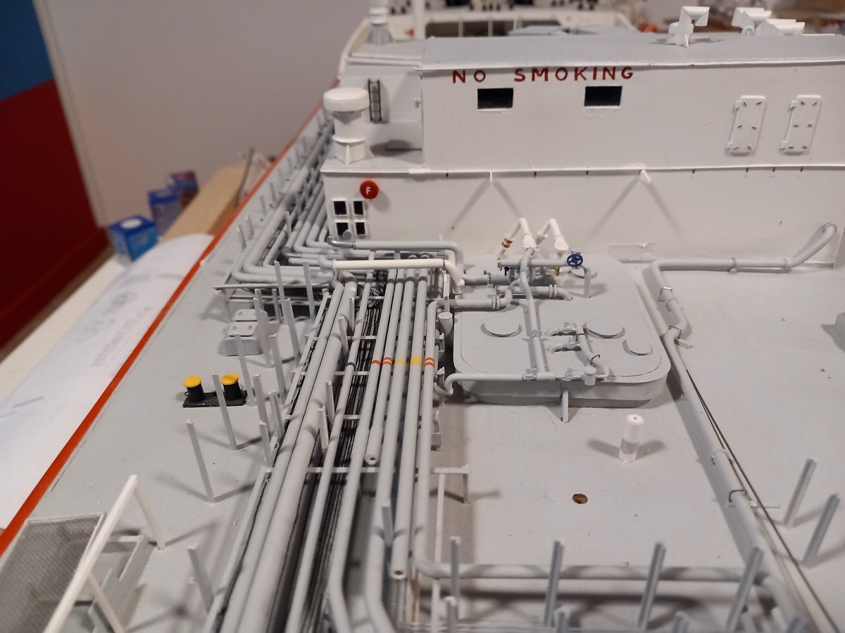
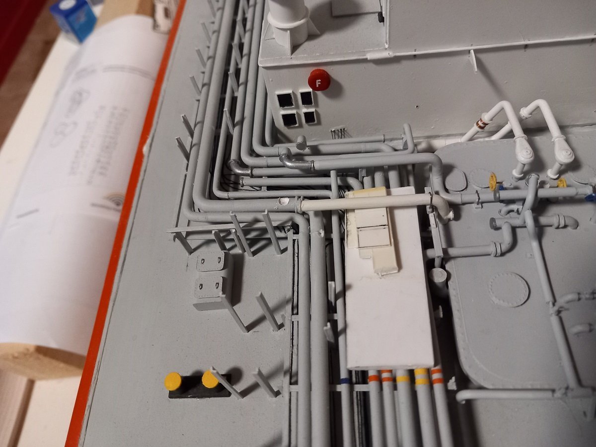
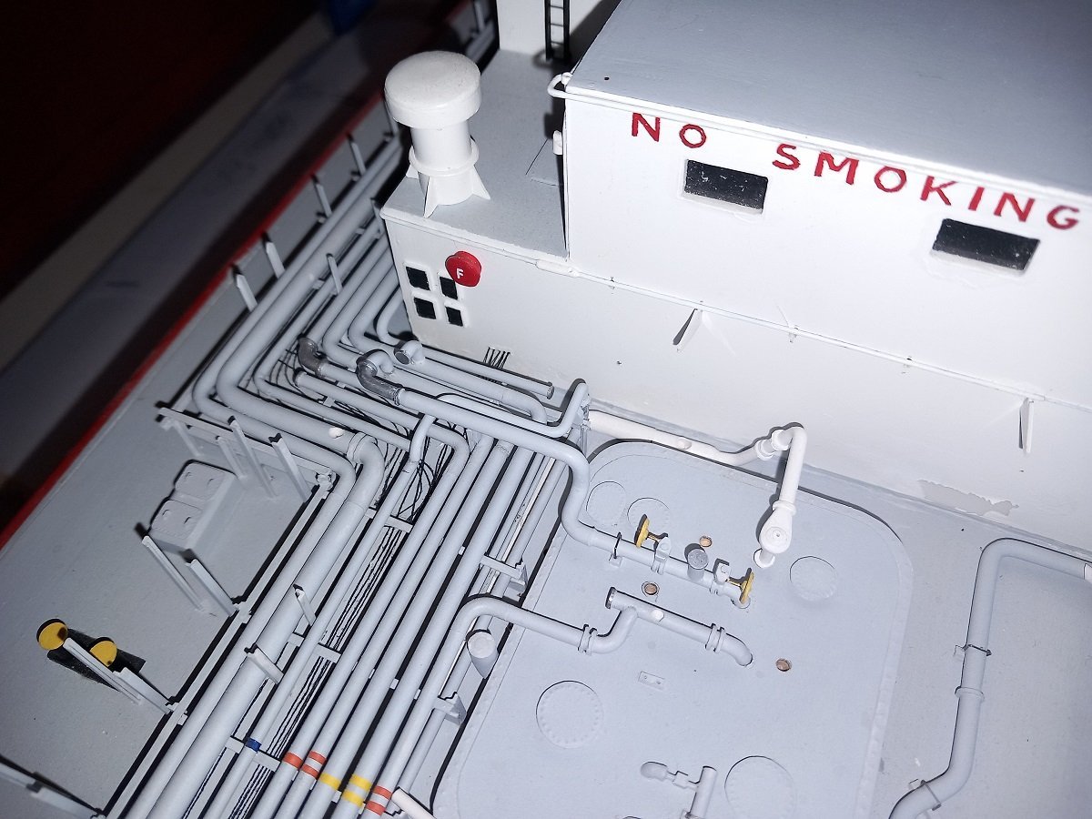
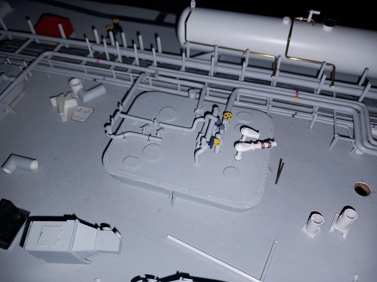
Thanks. Been a while again. Progress is slow, but I didn't expect otherwise. In the beginning I was wondering why I gave up in the past, but now I know... Although I made more detailed plans for the manifold area, it seems they weren't quite complete yet. I had to go back and study a large amount of pictures for some more piping in the heater area. At least I think I'm close to completing that now. Slow going, with a lot of dry fitting, adjusting, removing, placing supports, dry fitting again and so on. One of the most annoying parts of stopping for long periods of time is that you lose momentum and when things aren't complete, you didn't build enough parts, then you need to build something extra, much like you built the others years before... It appeared that I forgot to count and build one of the control and monitoring boxes (for the booster pumps in this case). Luckily I started building it some years back and only had to complete it now with handles and support legs. Next to it you see the new bunker manifold drip trays (of course I found the 4th original one when I started building the new versions...😂) And drip trays in position on each side of the cargo manifold (just a dry fit of course). On this picture you see another lesson I learned. On the left of the cargo manifold drip tray, you see a piece of deck that broke out. The lesson I learned is when you use a filler to level something, you need to make a boundary. This is the edge of the hatch, so if I had to do this again, I'd be putting two vertical strips, one on the hatch side, one on the hull side adjacent to each other and only then use filler and flatten it. Now, when the edges touch when I open/close the hatch, there is always a risk of breaking part of that filler. Too late to fix that now, with all the structures on it. And an overview of the heater area now. Most of the piping forward of the heater is just dry fitted. The white pipe, central in the picture was mounted too high compared to its connection on the hatch. I was about to leave it like that when I noticed it's actually too long as well. The flange connection on the left should be connected to a pipe floating in the air with a large elbow. Looking at the spacing here, there's not enough space for a such an elbow, so the flange needs to move forward. In short, I'll have to break out the aft support and while I'm at it, I'll also correct the height of these supports to match the height of the piece on the hatch. Once I complete this piping, I'm ready to move one layer up, I guess I'll complete the tank domes, last valves on tank dome 3 and some piping works and valves on tank dome 2 (you can see that in the picture of the primed crane). Then it's on to the bunker manifolds and bunker lines before moving finally up to the cargo manifold piping itself. I think I'll be doing that outside-in. First placing the flange connection and manifold valves on the manifold and later on adjust the piping to end up on the valves. It won't be easy, but like that at least I have the regular/proper spacing between the manifold pipes on the outsides. If it's just slightly off, it'll be a sore in the eye, while some inaccuracy on the piping itself won't be noticed.
-
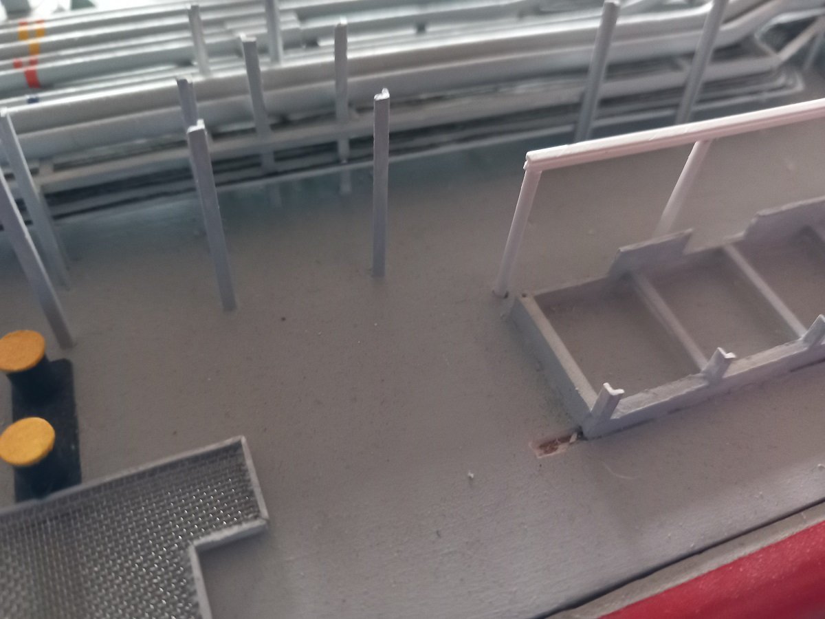
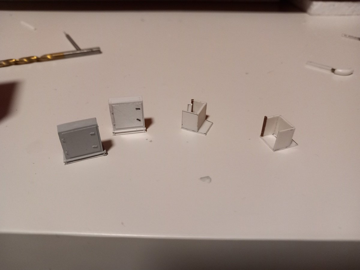
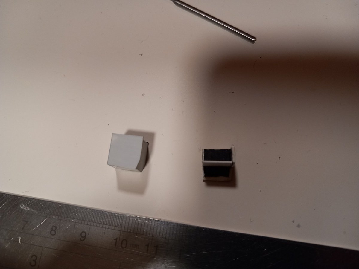
Thanks for the praise Michael, unfortunately it's more stubbornness than patience. Just too stubborn to give up on this one. Slow, but steady progress. The heater section is nearly ready for the lower layers, which means I can soon glue it in place and carry on with the next layers of piping near the manifold (yes, fresh CA has arrived). First layer will be the bunker lines for Fuel Oil and Lube Oil. They are stationed forward and aft of the cargo manifold on both sides, so 4 stations in total. They have their own drip tray below them. I built those 10 years ago, but figured out after a long search through all the pictures, that they were wrong in shape (size was ok). I started conversion back then, but didn't go through with it. Currently I only found 3 out of 4 back, so I figured I'd simply start all over again. Shouldn't take that long. As you can see below, the original was like a full box, while in fact, the bottom is somewhere in the middle. The crane is now a little further advanced and put in primer. It used to be white primer, but somehow it turned brown inside the can. I can live with it. It clears out any markings and contrasts for the later white coats.
-
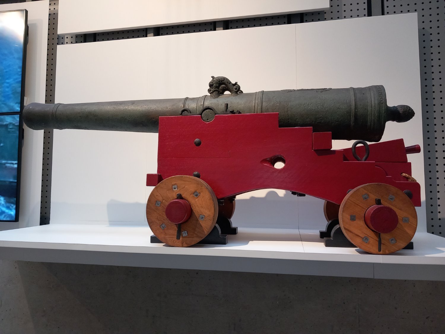
Seems the Dutch had very similar guns. This one also had the stepped (Z) carriage sides. Unfortunately displayed on an elevated stand. Could only read "Cornelis" at the back, which I assumed was a manufacturer?

- 2,696 replies
-
- 10
-
-
- heller
- soleil royal
- (and 9 more)
-
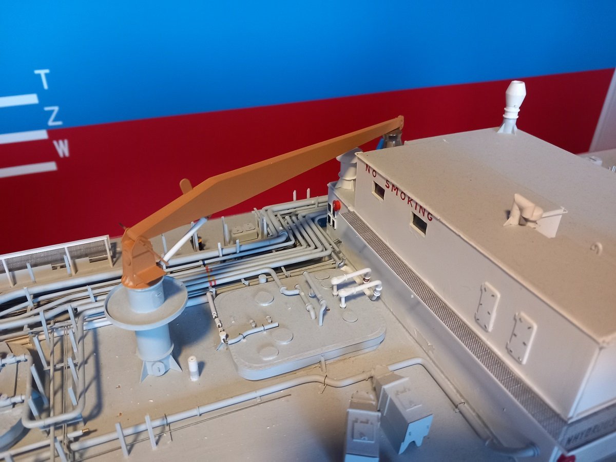
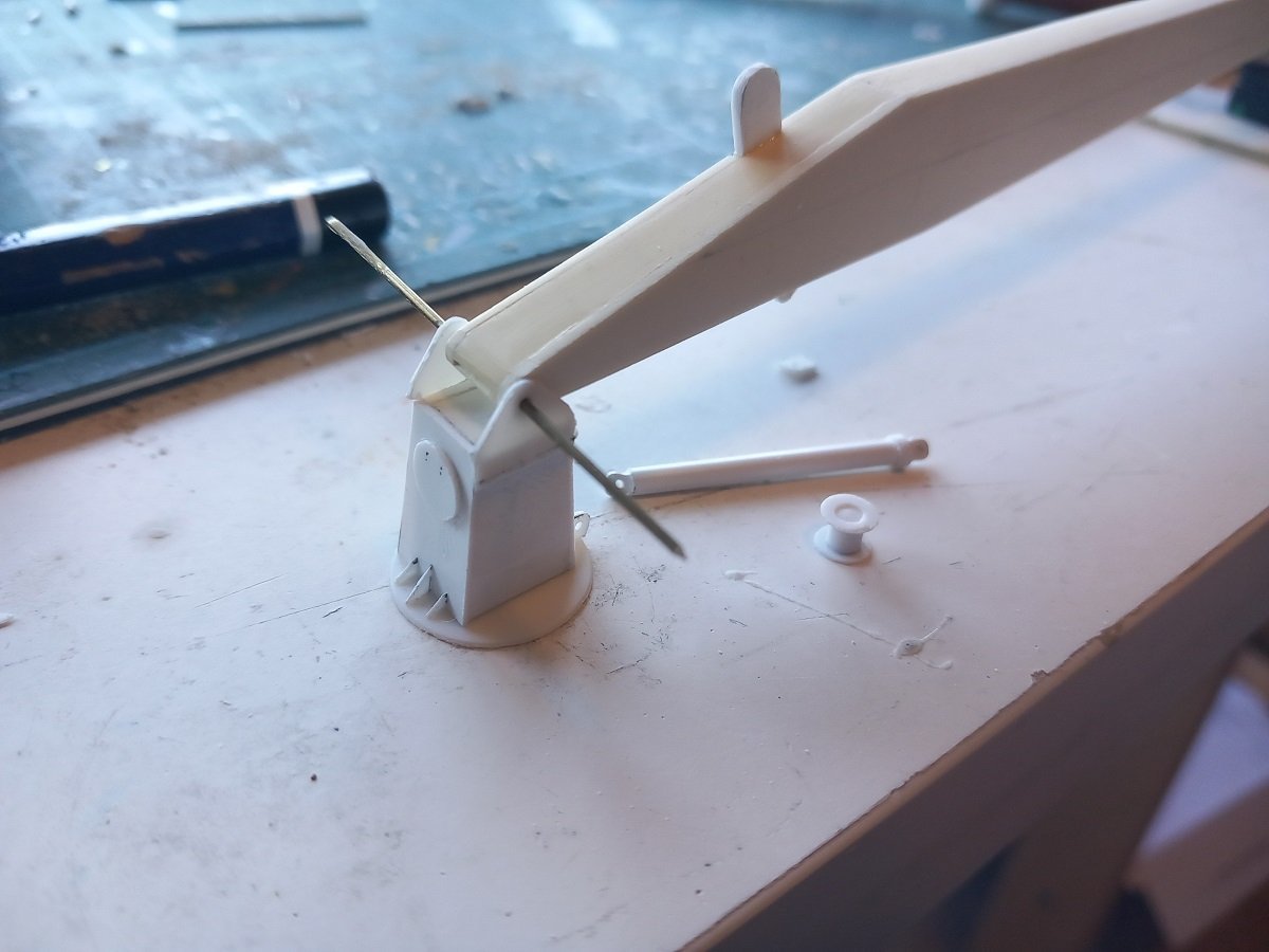
I ran out of CA and seem to have underestimated the amount of mixed materials I'm using on this model... The heater system is itching as I've generally fixed the hottest items, but am unable to glue them in place now. The pipe on the starboard side, right side of the heater in following picture, is the determining pipe. The most complex one, and although bent as accurately as possible, it's never a 100% fit. Therefore, this pipe determines the fore-aft location of the heater itself. The (white) pipe on the left is the heating water inlet and is then placed depending on the final position of the heater itself. As a last step, the last bend of that pipe to fit the water pipe in the pipe rack, will be made last. So next step, gluing the last supports for the right pipe, glue the pipe and heater in place and then adapt the waterpipe, add its supports to deck and place it. The supports and placing of the white pipe on the right is also ready. This is the heating water outlet and will be connected to the top of the heater later on. Since I'm out of CA and I want to reach my goal of at least 2 parts per day, I continued with the main hose handling crane. This crane is used to handle bunker hoses and cargo hoses as well as cargo reducers (adaptation pieces for the manifold pipes to make them to the correct diameter for the shore installation). I had the boom for 10 years now... I also had the base for 5 years or so, since this is the 2nd version of the base. I now continued with the bottom place, reinforcement brackets etc. Also made the gearbox for the wire drum and the wire drum itself. I used my faithful leather punch for the disks of the drum and a piece of styrene rod for the drum itself. I'll finish this crane, but not put it on the vessel yet as it would impede work on cargo tank dome 2 and the manifold piping.
-
It looks good, so I'm pretty sure you didn't screw up. She's gorgeous. Guess you'll be cold for a while, while you wait for new fire wood.
-
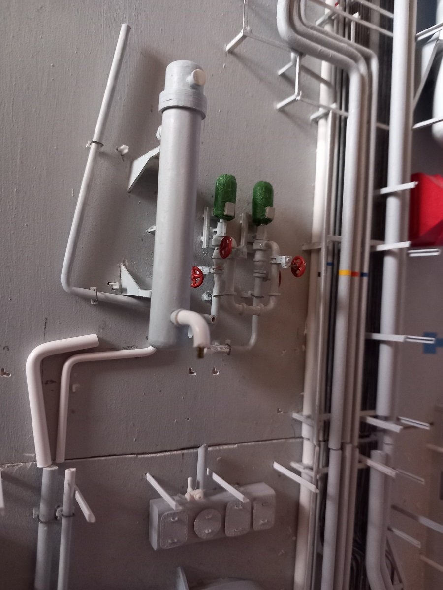
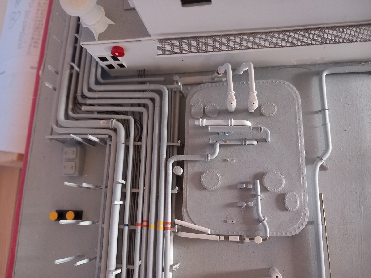
Here we are then. Attempting to untangle this spaghetti around the heater. I also took an easy start at finishing tank dome 3, finally mounting the valve actuators and wheels. Sorry for the dark pictures. Tank dome 3. Note the white things, cargo tank safety valves, are just dry fitted. The copper rings are part of expansion bellows that allow the line to the vent mast to cool down rapidly without damage when the safety (overpressure) valves suddenly open. Currently they are dry fitted since the vent mast to which they will be connected, would be in the way of other works around the deck. In the back you see another recent addition in form of the pipelines to the deck tank. The beginning of the spaghetti. I had made most of these pipes in the past already, however, never glued them in place. The horizontal U-shape is one of the difficult parts, as its connection towards the heater is at the bottom of the U, I now need to match a very complicated pipe towards the heater. The heater is still loose on its supports, which allows me to at least move it a bit fore and aft, depending on the connecting pipe. Quite some work to do, but luckily it's mostly limited to 1 or 2 real choke points. Once I get past those, it should get easier.

-
although I had seen your log before, I hadn't found the time to read al 15 pages of it. I did that now... What a great journey you made. Fantastic result so far. I'll remember: - copper tape, fantastic - CAF instructions (which ones?), not so fantastic - it comes in 5 sessions (seems like people asked a 100 times) and quality-wise it's pretty good - she's huge - you made a fantastic model of it (but I said that before)