Javelin
-
Posts
300 -
Joined
-
Last visited
Content Type
Profiles
Forums
Gallery
Events
Everything posted by Javelin
-
 I'm no specialist on submarine decks, but in those days subs spent most of their time on the surface. I would imagine their decks would not be that dirty, much like the hull above the waterline as algae etc. wouldn't get time to get a grab on those parts. I would imagine they'd keep it cleaned as much as they could to make it less slippery as well. The ageing and tar of the wood would probably give some contrasts, but not sure if it would as visible as what you made. That said, most people won't make that kind of considerations when looking at your model. If the weathering of the deck matches the rest of the build and you're happy with it, that's fine.
 -
That's great news all around Keith. Hope Maggie keeps making progress. Great to hear she's gotten this far already. Great to see you're getting "some time off" as well.
-
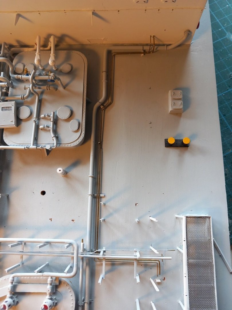
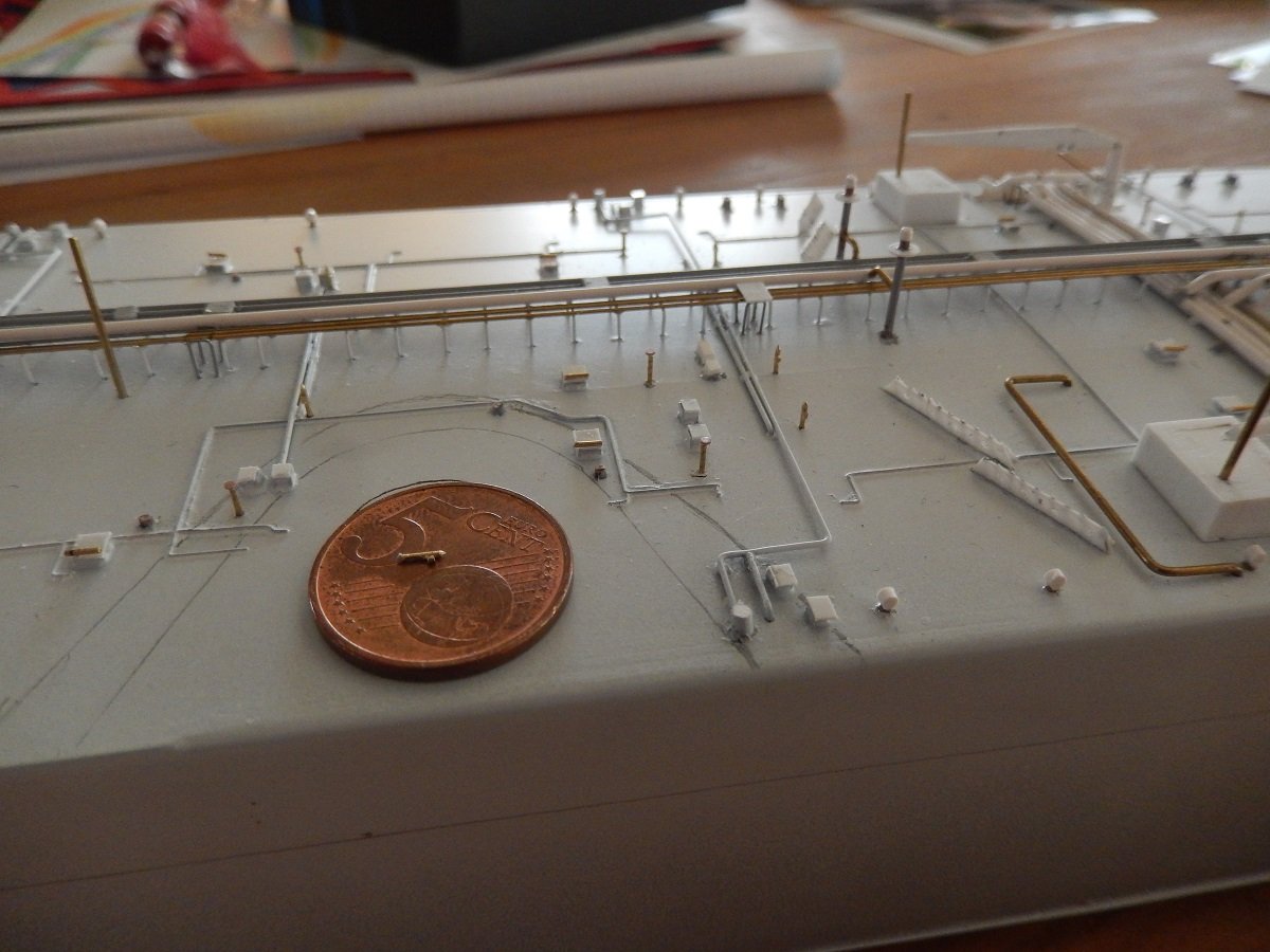
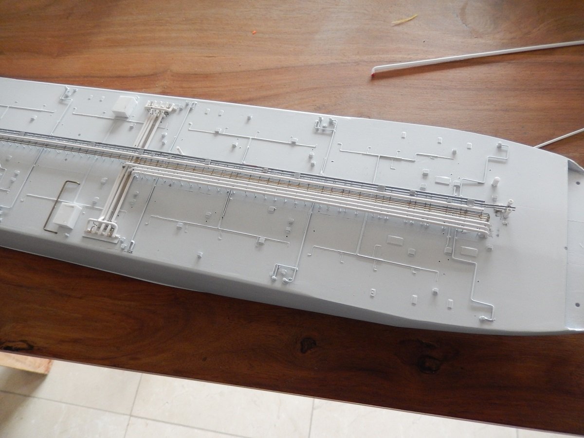
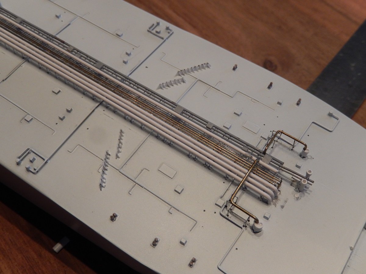
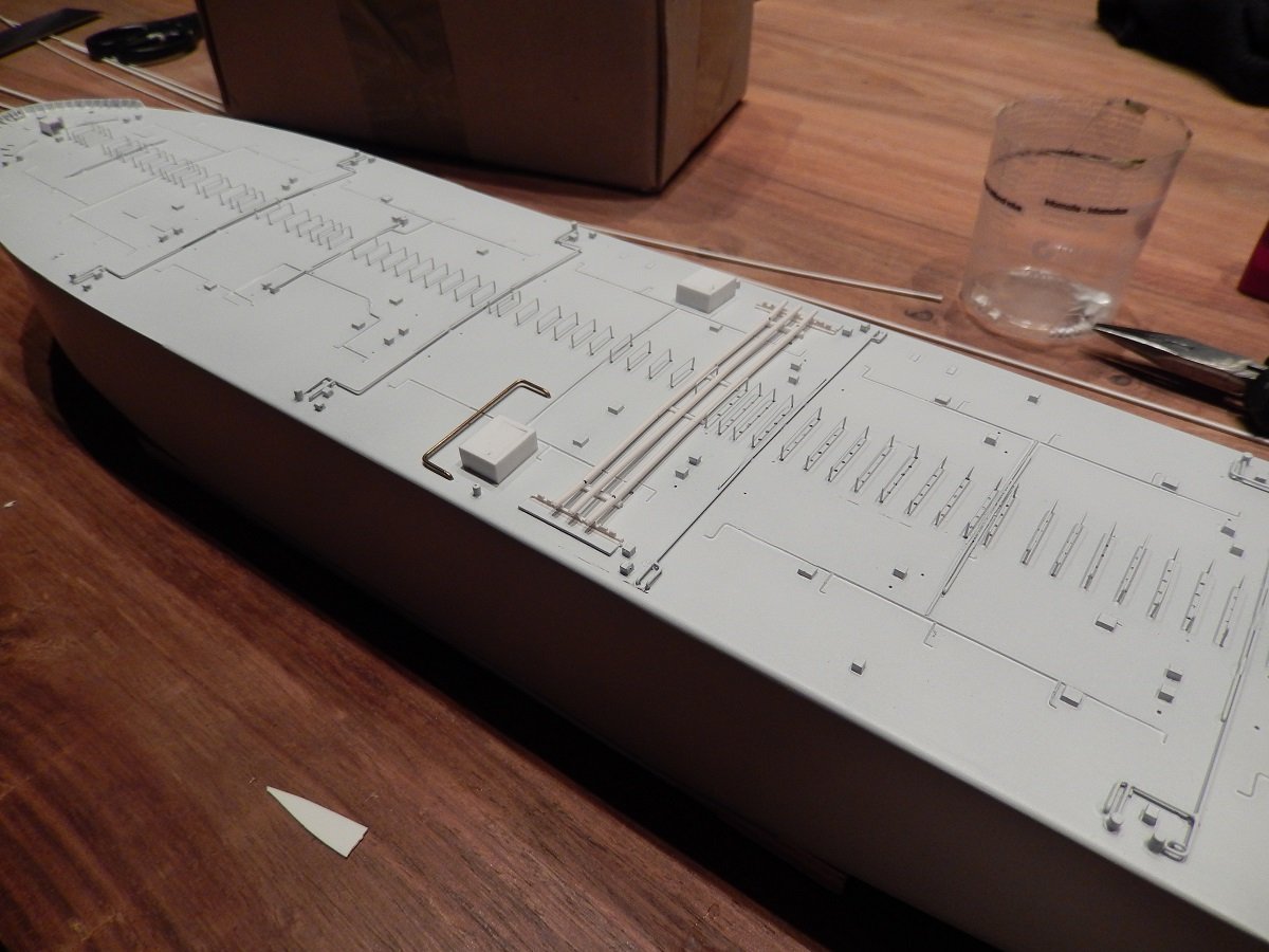
So, time to continue. I do have plans now, but still I need to think about the sequence of construction. I also had some hesitation regarding 2 small pipes coming from the compressor room towards the manifold. I had made provisions for those pipes in way of making large supports on the big pipe to accommodate them, but I was never sure if I'd place them after all. Eventually I decided to place the pipes. I had put part of a pipe below that manifold. It didn't look right, so I removed it and built those pipes in different sections. The joints next to tank dome 2 will mostly be covered by the platform shown in previous posts. In below picture you can see the brass pipes running parallel to the big pipe. The joints are hidden in the shadows. The reason I had to put them now was of course that they were also a bottleneck for construction of the manifold. I wouldn't be able to place them if I continued further on the manifold. And I've started the structure of the manifold on portside. All beams in place here.
-
@Roger Pellett, Although I understand and agree to most of your post, there is one note. Steam Turbines are still used today. Up to 2012, new LNG carriers were still often built with steam turbines. That particular type of vessel required the boil-off gas to be burned in order to control the cargo tank pressures (and not vent it to the atmosphere, which they routinely did in the past). In order to burn that gas, a dual-fuel solution was needed and steam boilers provided just that. Each boiler has/had multiple burners with the choice for each burner to burn either natural gas or fuel. The equipment was generally Japanese, Mitsubishi Boilers and Mitsubishi or Kawasaki turbines. Generally a large turbine (one High Pressure, one Low Pressure and one Astern turbine mounted together)for propulsion and 3 turbo generators for power supply (backed-up by a diesel generator). Another advantage of this set-up was that, when not underway, a steam dump could be used, this steam dump allowed to burn gas, although there was no demand of steam. The steam would then simply be condensed and the energy given to the sea. With the advent of the much more efficient dual-fuel piston engines, the steam turbines went out of fashion. In order to get those piston engines working, they did need a way to control the tank pressure and that came in form of reliquefaction (very inefficient energy-wise) and Gas Combustion Units (GCU = basically a big flare in the funnel of those vessels). That said, the steam vessels are still around, although they come much cheaper (and therefore not very attractive for the owners) and are only used when the gas tanker market is tight. You also see them increasingly being used as storage units nowadays. In the past I actually did some operations with very old US built LNG tankers of the Aquarius class. All in all there are still quite some steam engineers around, although of course nowadays they are increasingly rare. Of course United States tech is indeed way behind on technology and renewing it would cost an arm and a leg. As you mentioned business and legal wise, it's probably not the best idea to even try this. Looks are however deceiving. Her appearance may not be too good now, but given a good sand blasting and coat of paint she'll look the part in no time. Perhaps she can be turned into a hotel. I recently slept on SS Rotterdam, an old liner in the port of Rotterdam. Part of the vessel was converted as a hotel, machinery spaces etc. can be visited (paid tour of course) and part of it simply off limits. I assume they try to reduce costs by limiting the amount of the vessel that is used. All in all an economical exercise, how many people do you expect to accommodate at any time and which features do you want to maintain.
-
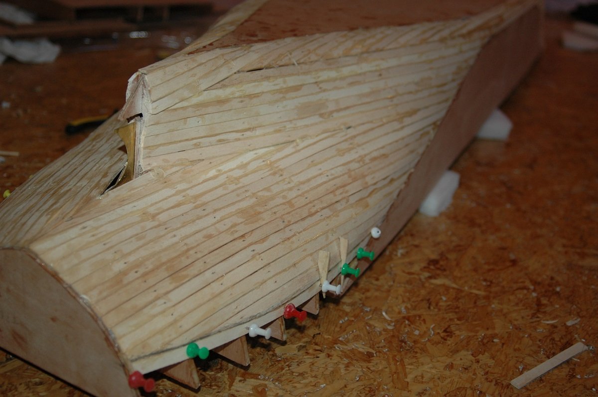
Here you see what I tried to describe. This one is in wood, but the same method can be applied in styrene. It avoids compound curves, which styrene sheets, like wood, won't handle either. Depending on the curve you can adjust the thickness and size of strips you use. I didn't apply filler on this wood hull as it would be covered by fibreglass (RC model), but with styrene, some filler will give good results.
-
I wouldn't try to connect styrene to wood. Due to the different expansion coefficients it's likely to crack at the seams. It's not fully clear to me what the shape of this vessel is from the plan, I'm assuming a twin prop -twin rudder configuration? If you want to go full styrene, I guess making styrene strips (=planks) over styrene frames will be the easiest way in such an area. Afterwards you can fill the gaps with filler and sand smooth. For the stern itself I'd make a false stern/last frame to end the planks on, then level all planks there and put the full stern plate behind that. Although I'm mainly a styrene builder, I must admit for such a size model, I'd prefer wood. Styrene becomes very brittle and if you're making such a large detailed model, it might as well last for a while...
-
I could use a million of words of admiration, but I'll just keep it at "wow, what a masterpiece !" (for now).
- 486 replies
-
- 5
-

-

-
- vanguard models
- alert
- (and 1 more)
-
Flag with ship name reversed on one side?
Javelin replied to daschc01's topic in Masting, rigging and sails
kind of funny. I just saw this question and this very evening I stumbled across this painting: Michiel Loos merchant ship The name on that pennant, indeed the vessel's name, is also reversed... and the pennant colors in exactly the same style as yours. And yes, I know, funny, the flags are pointing aft while under sail... -
https://www.google.com/amp/s/amp.cnn.com/cnn/2024/04/23/business/baltimore-bridge-collapse-lawsuit-hnk-intl And there come the lawsuits.... As if they could have handled it any different. Can't quite blame the city for it, but on the other hand, these are the risks of maritime transportation. If you're not prepared to accept it, better to close your port then. In general some of the most outdated maritime infrastructure can be found in US, time for them to get moving on this. Also the reason the largest containerships nowadays can't even call any port in US. Their closed market, including in dredging, creates a huge disadvantage compared to the rest of the world.
-
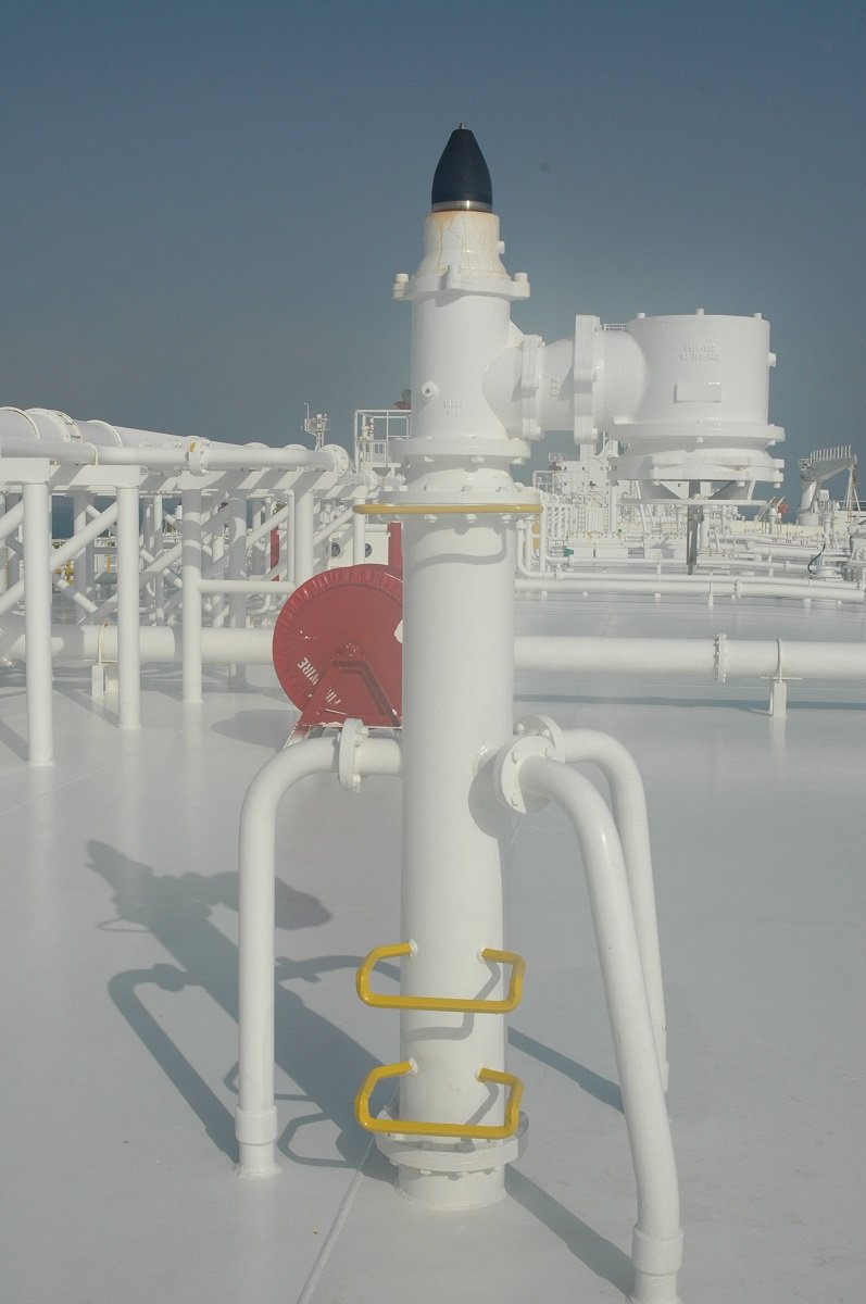
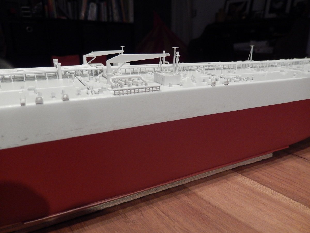
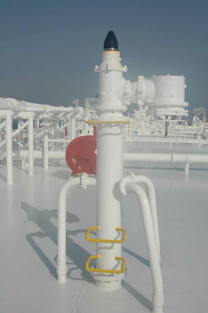
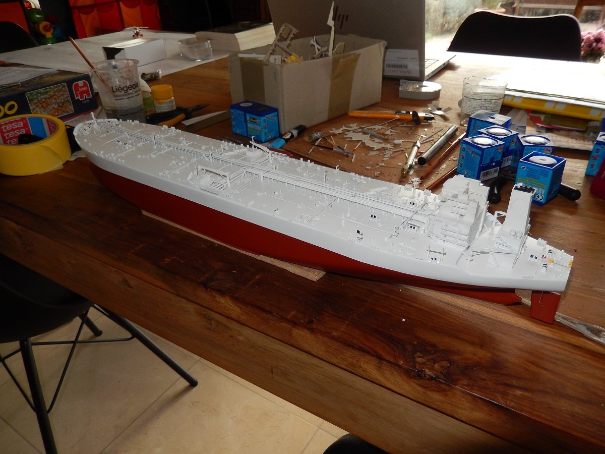
Hi, Thucki, it's not insane detail. It's a balance between having something that looks a bit like the real thing rather than having nothing at all. The real P/V valves for example, look different from what I produced. Pretty sure PE experts would succeed in making it all look 100% accurate, but I'm trying to find a way in between. As mentioned I actually don't like all that detailing, but in order to making a convincing model of a tanker, you need to at least create a certain amount of clutter on that deck, whether it's accurate or not, doesn't really matter to most people. In my case it's accurate to the amount of devices etc. on deck, but not necessarily to what all those devices look like. Here is a picture of the actual P/V valve, something I represented by a small piece of brass sharpened at the top, with a small cylinder stuck to it on the side. (and you can also see that red fire wire reel behind it) Jerome, I guess those rub-on letters are what I make with my stencil cutter. The question for now is whether the cutter can make them small enough to match the scale of this vessel. I used it successfully in my build of the split barge Bengel, but that was in 1/400. Arguably a smaller vessel with smaller lettering in real life as well. If I'd make those letters just slightly smaller, they might actually be good enough for the Europe. I'll probably give it a try sooner than later. Considering I'm out of pictures on this one, this is likely to be the last post (except when my stencil cutting trials would work). The anti-fouling came out rather nice. You can also see the size of those big warts for the anchors. Although I wasn't planning on any railing, I did have to add some details to the sides as well. Again, to make it more convincing. Those details, fairleads and the heavy manifold railing (made to carry the weight of cargo transfer hoses during ship-to-ship transfers) would also be visible from a distance on the real ship. In order to make the heavy railing, I used a piece of "normal" 1/700 PE railing, modified it a bit and then used it as a framework to add heavier stanchions and the top bar (brass wire). This way I had a consistent distance between the stanchions and straight line-up. And here the railing "in action", being used what it's made for. All tankers have those since sometimes on terminals hoses are used instead of loading arms. I also decided to add the markings for the bulbous bow and the arrows for the locations where tugs are allowed to push. You need a lot of tugs to push something this size sideways through the water. Those shapes were easy, so I cut them from a piece of masking tape and simply painted them on. And finally the funnel. The Tankers International sign was also painted, using maskings in several steps. The end result of this vessel is visible in the gallery. Seems I hadn't taken any pictures with the lifeboats on, except for those final pics. I also had to think for a very long time whether to add the floodlights on the masts around the deck as well as the accommodation. Eventually I decided it was necessary, to give the masts a purpose and for general appearance. Those are just small squares mounted at a downward angle. They can also only be seen on the final pictures.
-
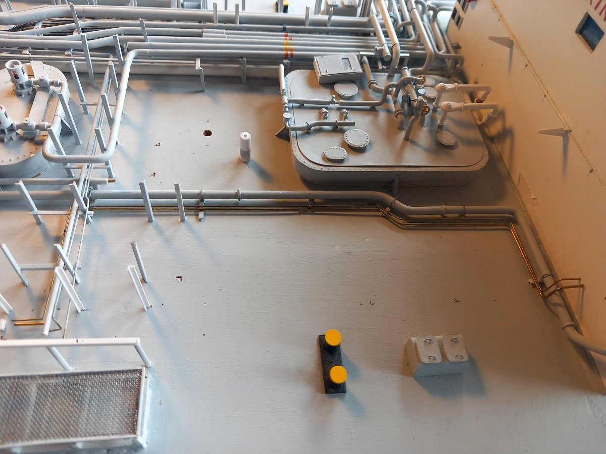
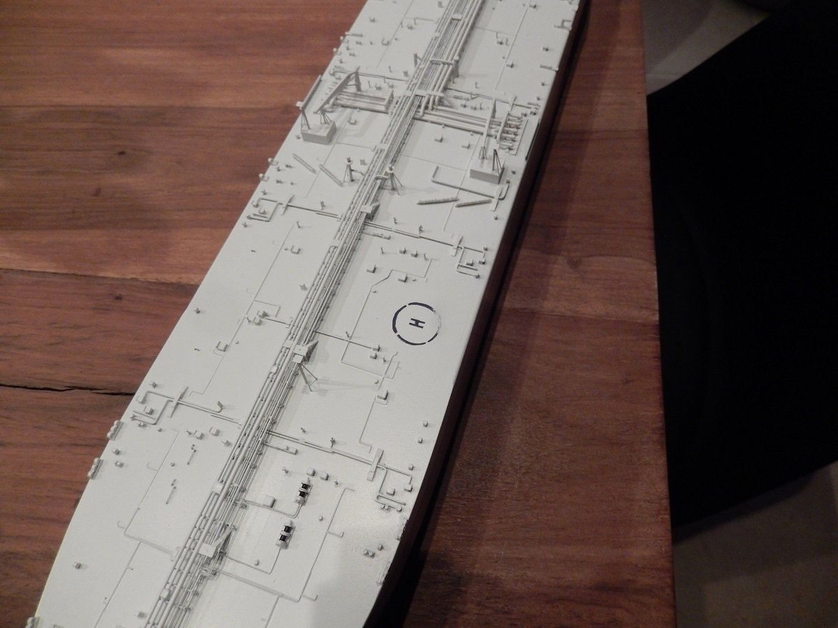
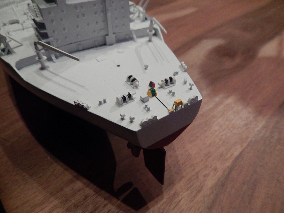
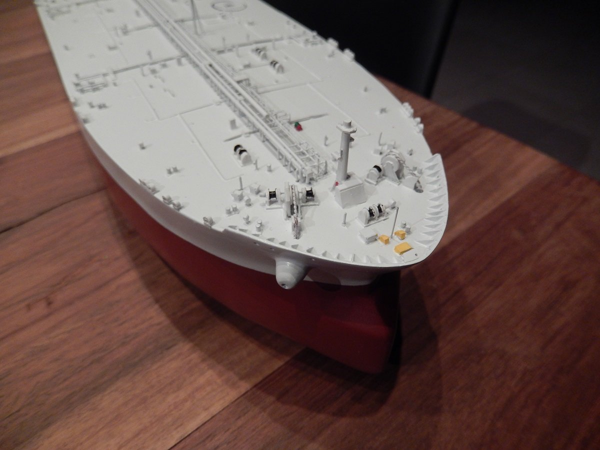
Since I'm back at the workbench, I'm more or less on schedule to finish this topic and continue on my real in-progress work. Here is a better view on the lay-out of the caps that were below the masking. Some details were then also coloured, a nice distraction from all the white. Forward and aft some red winches, those are the fire wires. Two wires that were hung over the side and made fast on bollards. The eyes are normally kept about 1m above the water, so that in case of a fire, tugs could grab the wires and pull the tanker from the jetty. You have to take into consideration that it takes about 1 hour to get a tanker's engine ready, so they can't move on their own power on short notice, even if they wanted to (not much you can do without tugs though). Nowadays this practice has been discontinued. Only a few ports still require it. It was found that hanging these wires caused quite a few accidents, while in reality the tugs would probably either break the wire or destroy the bollards if they really had to pull a ship off the quay like that. The added value didn't add up against the disadvantages. The yellow details are the emergency towing gear. Any tanker has two Smit brackets on the bow, basically very strong points to connect tugs to. The box in front contains the chafing chain, a chain that's normally made fast to these Smit brackets for the towing. Chains can handle immense forces and are resistant to chafing and fire, therefore they chose a chain for this purpose. This gear is there to tow the ship on high seas, sometimes for longer voyages in case the engine would be disabled. She ship and tow can move considerably during such oceanic tows, so the chain has its purpose. On the aft there is a big reel with a pretty big wire on it. The yellow box in the back contains a buoy with light and a messenger line connected to the wire. In case a tanker would want to assist another vessel in distress, the buoy and messenger are released into the water to be picked up by the other vessel. The wire is rolled out fully until it catches a strong point. Once the wire is connected on the other vessel, the tanker can tow it. This could also be used by tugs to tow the vessel. The aft system is only required from a certain size of tanker. And then came the helo deck markings. I very rapidly found out I should have tried to mark this before adding the piping around it. I couldn't really put the masking in a decent way. I didn't have a stencil cutter back then neither. All in all it ended up becoming a bit of a weak point on this vessel. Nowadays I'd do it better. In below picture it was only started, more lines (and more difficult ones) still had to be added, going through that piping too. I did correct it a bit afterwards, but still something I'm not proud of. Due to my lack of stencil/decal ability, I also didn't add the name of the vessel. 1/700 is too small to actually paint it. However, since I do have a stencil cutter nowadays, I may revisit it and see what I can do with the stencil machine.
-
It's a great story John. I'm definately curious where this will go. I'll be following this build.
-
Hi Keith, yes there is, not a real pad though. It's simply an area marked on deck. The area is also kept mostly free of piping and the railing on the side can be folded down. Anything sticking out from the deck is also highlighted. Of course there is no helicopter landing officer onboard, but the crew have a bit of training on these things as well.
-
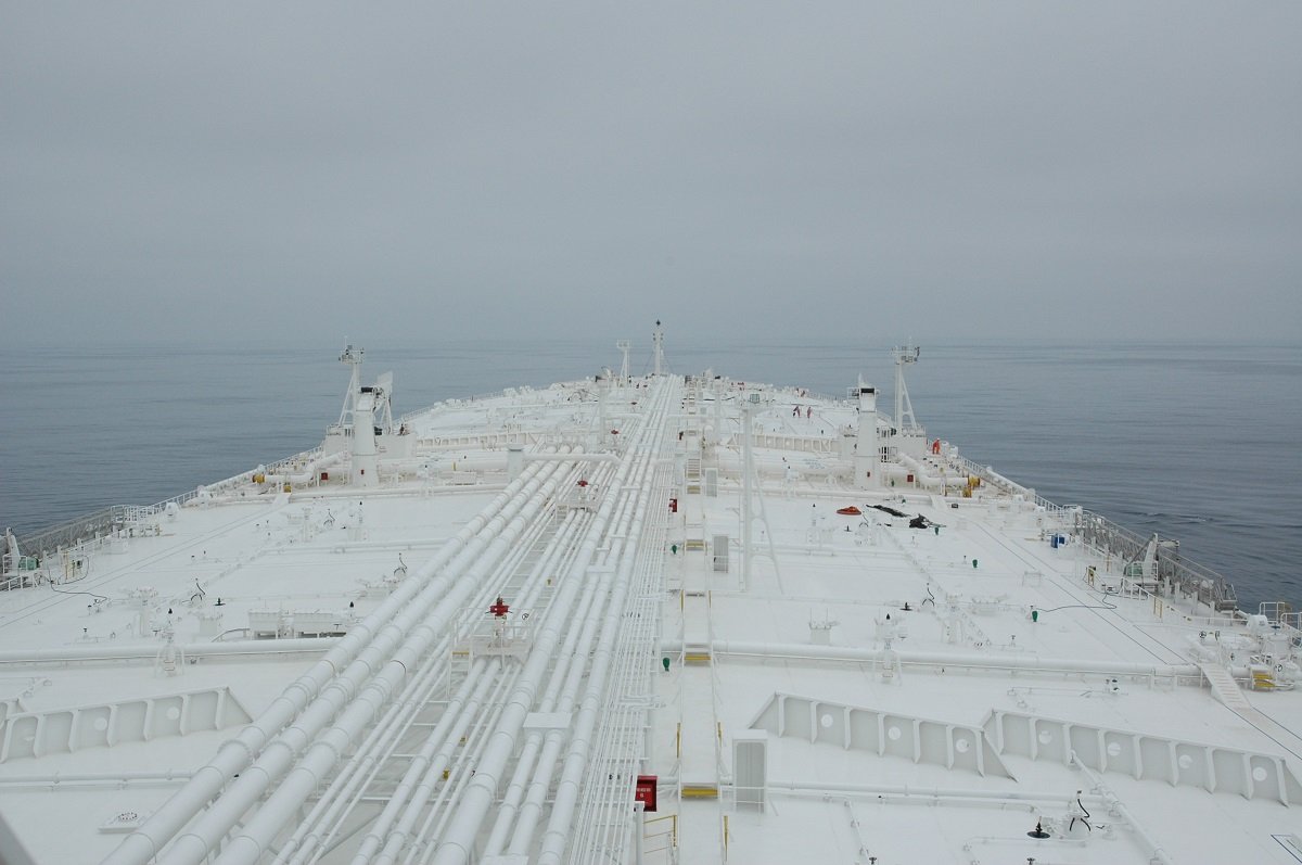
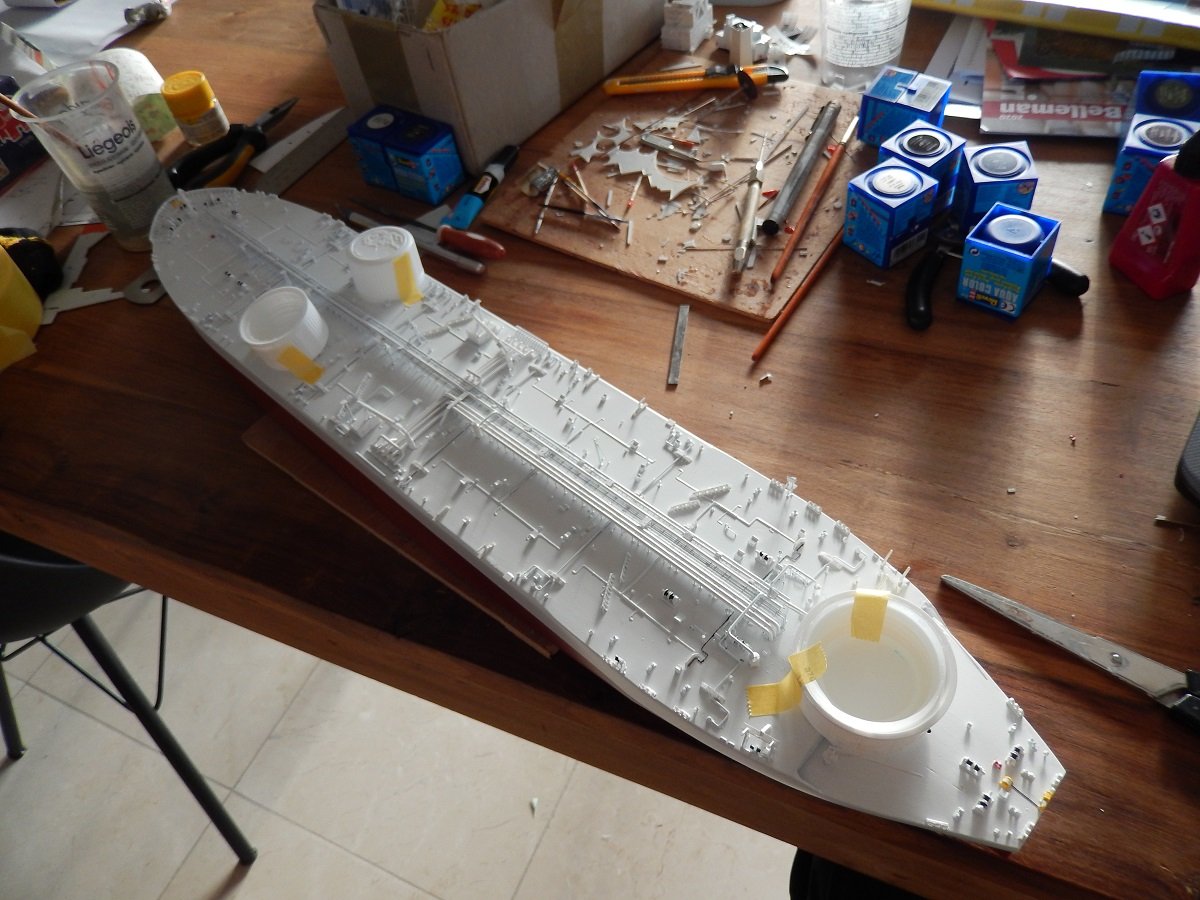
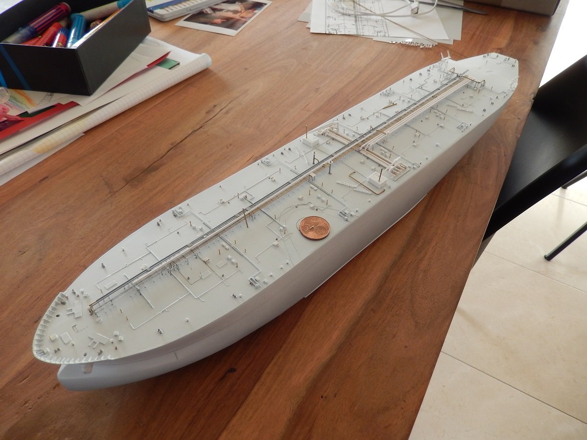
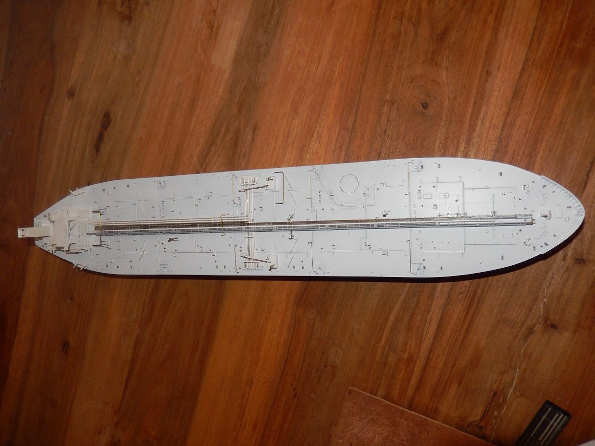
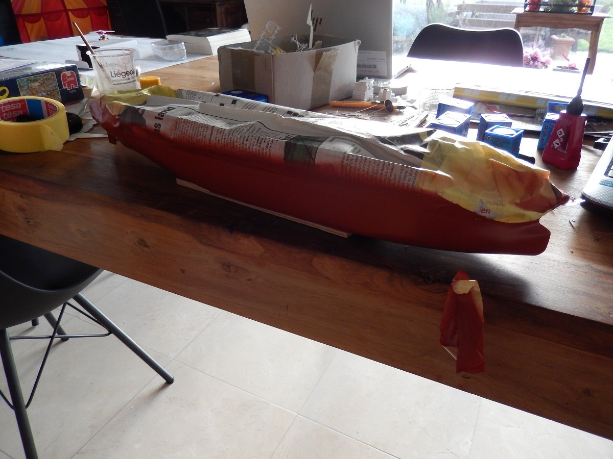
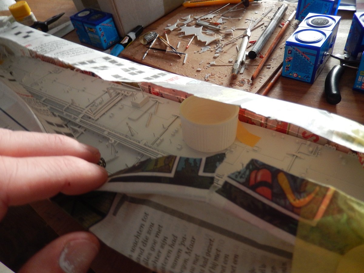
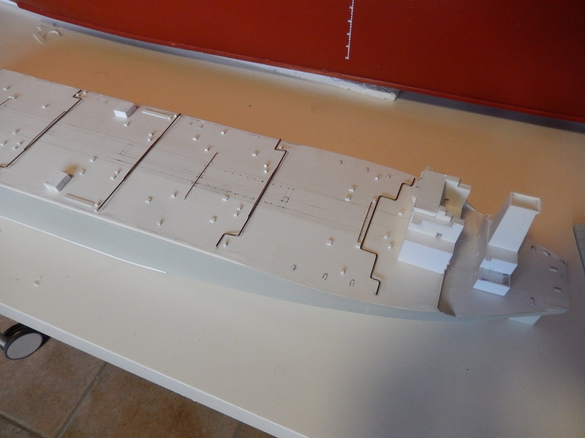
For sure it would be a long tour... It effectively takes over 5 minutes to get from the bow to the accommodation. Really annoying when you had a job near the bow and you forgot a tool! Then it was time for the finer detailing. Each tank has some P/V (Pressure/Vacuum) valves that stand on deck. They release gas when there is an overpressure and suck in air when there is a vacuum, although that vacuum is normally prevented by topping up with Inert Gas. They are only safeties. I built the overpressure part from a brass wire with a sharpened point, while the vacuum part is just a small cylindrical parts stuck to that wire. A whole forest of these things all around the vessel. Although there are only 3 cargo pumps, that doesn't mean there are only 3 cargo tanks. There are large center tanks, with on each side smaller wing tanks. And each one of those cargo tanks has its own P/V valve of course. And an overview of the nearly completed deck. Mainly the mooring winches and fairleads are still missing. And then it was time to get that bottom painted. Sprayed it with a spray can, easier with this size of vessel. Masking is of course tricky over all the details. To avoid any damage and to be able to turn the vessel around for spraying, I stuck some high bottle caps to the deck, where space was available. They were stuck there with some masking tape before I applied the mask of newspapers and masking tape. You have to make sure of course that the caps are higher than the highest details 🤪
-
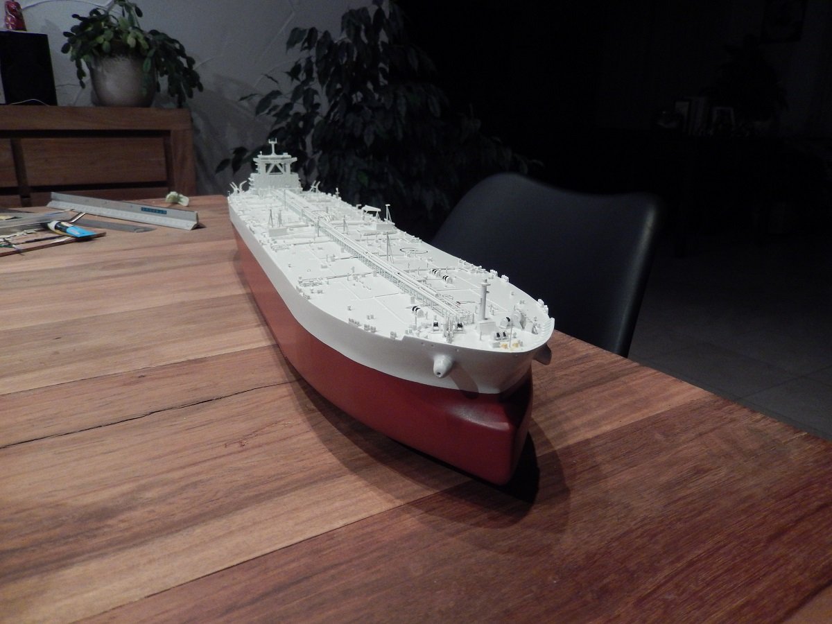
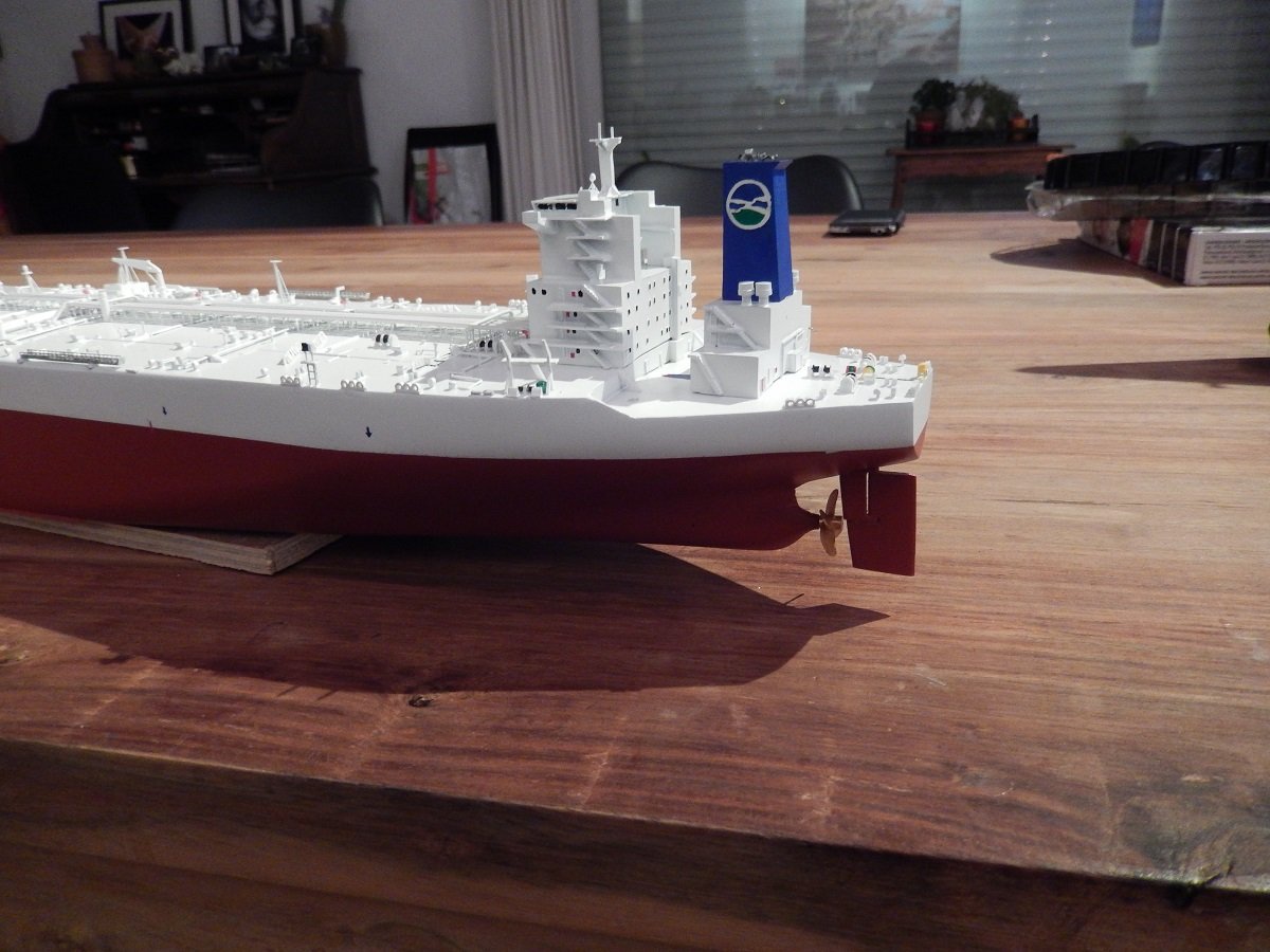
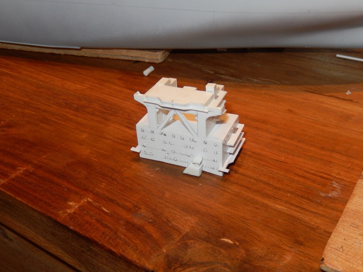
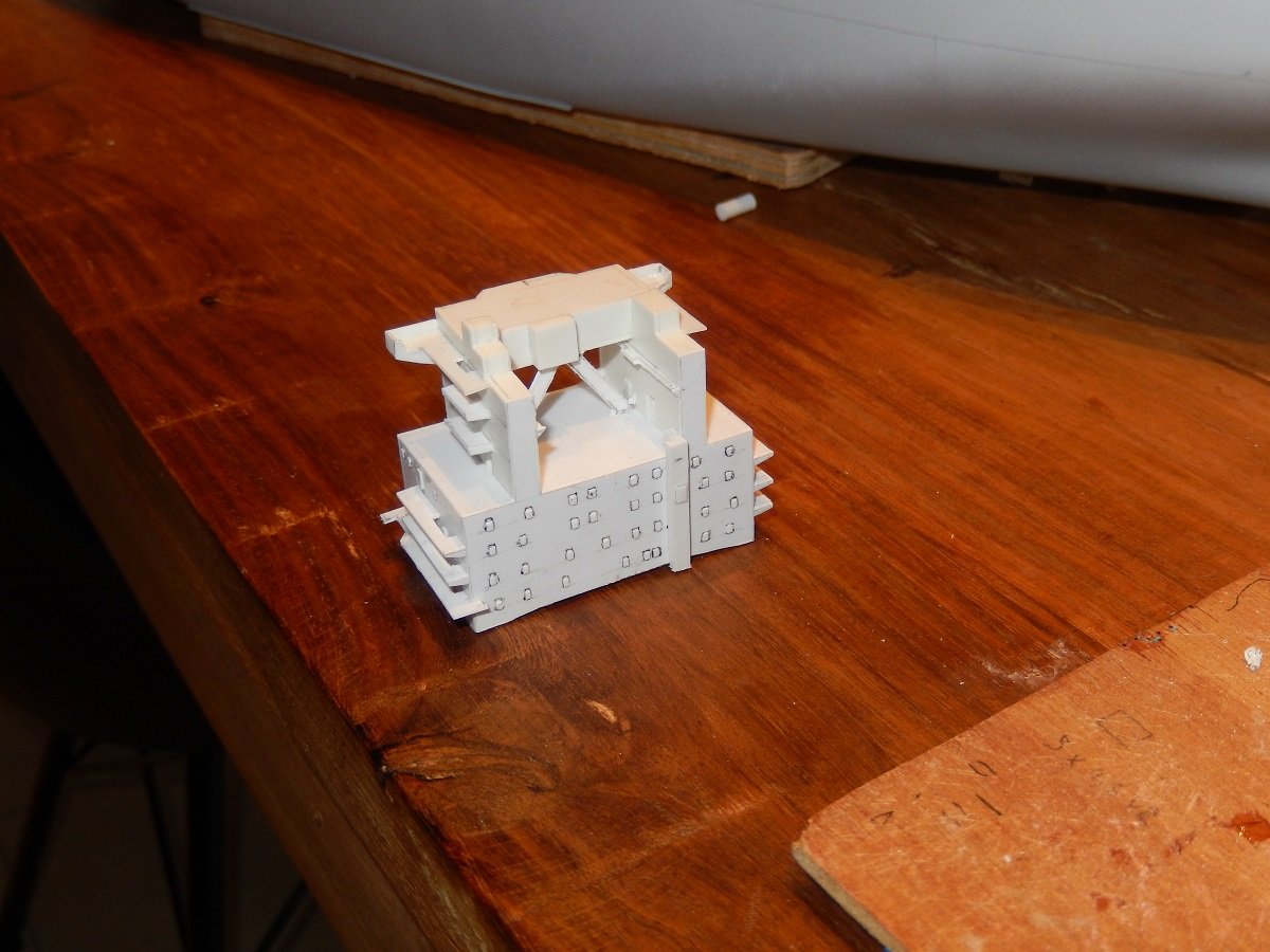
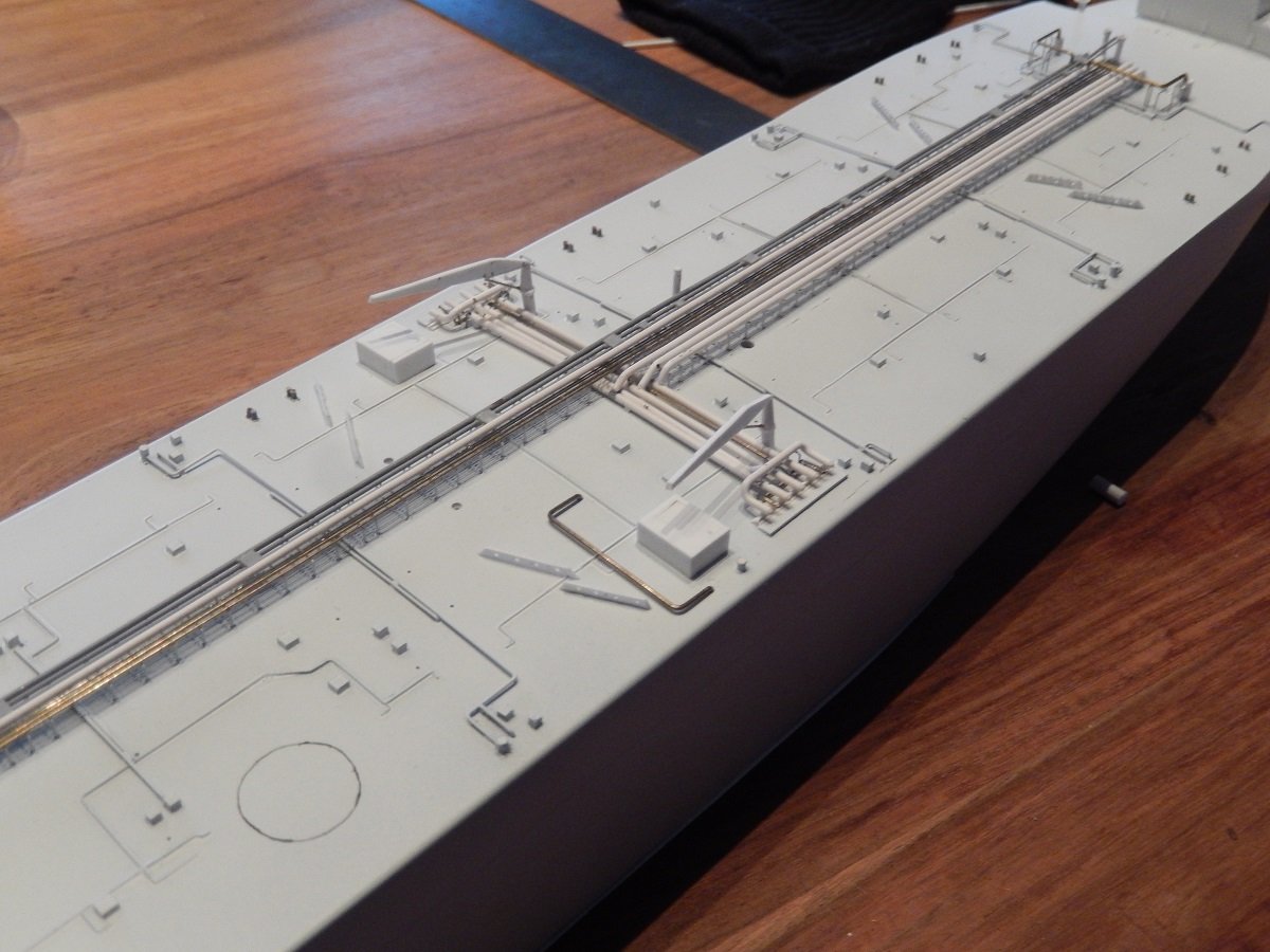
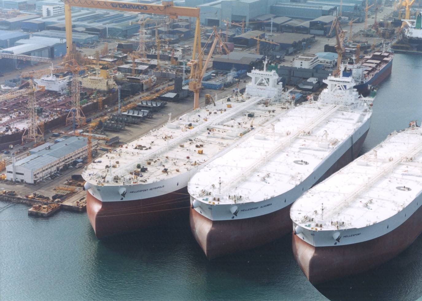
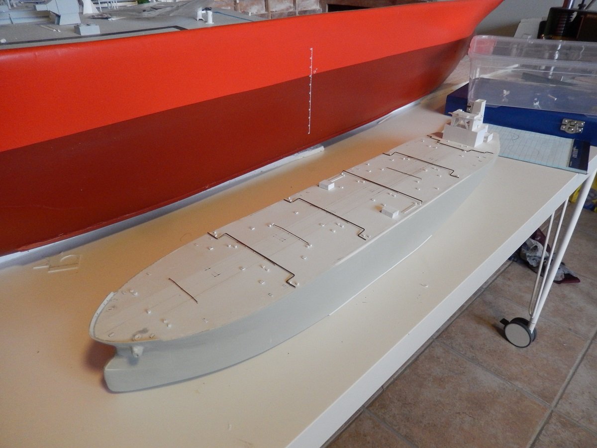
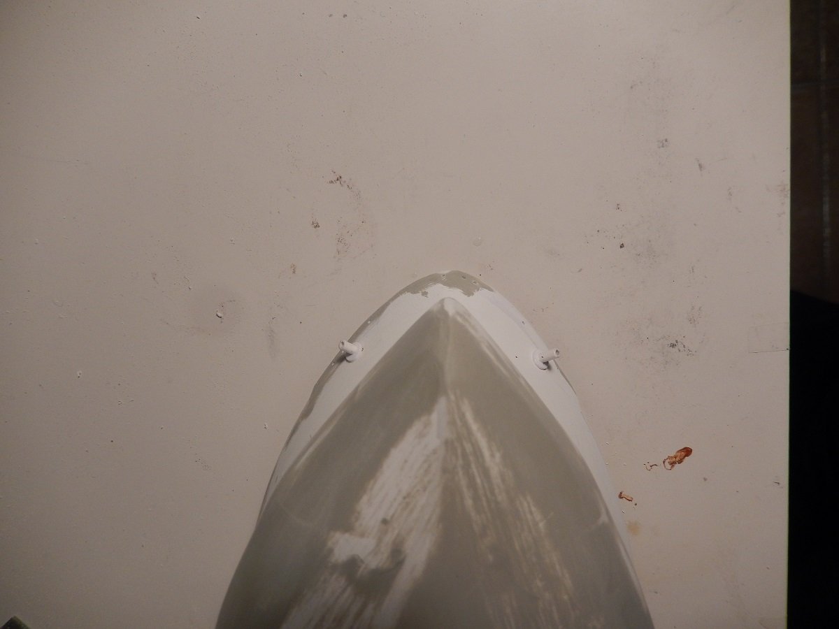
Thanks Keith, Thought I didn't have so many pictures of this build, but it seems I was wrong. In any case. Next were the prominent oil cargo piping going from the pumproom (where three pretty potent cargo pumps are located) to the manifold area. Furthermore there is also the line with all the small boxes, which in fact is just a duct for electrical cables, with the boxes being junction boxes in between. And then the last layer of piping is a few connection pipes at the aft end where the Inert Gas (in this case produced from engine exhaust gas) is sent from the engine room to the cargo tanks. These inert gas lines are also connected through a water seal that will overflow in case of overpressure in the inert gas line or the water will be sucked into the line to eventually let air in and prevent vacuum. These seals are located in front of the accommodation between the engine room pipe and the deck pipe. You also see the aft set of wavebreakers and some bollards on deck. Slowly going up, so next were the cargo hose handling cranes And some vent masts that allow to vent cargo vapours and/or inert gas to a safe place without endangering anybody on deck. The accommodation block itself has a surprising amount of detail that even I wasn't aware of... Luckily I had some pictures as well as a lot of pictures I found online, to get the puzzle together. And time to mark the waterline on the hull as well. I always paint my hull fully with the lightest colour (be it the hull colour or the anti-fouling colour), so that I don't have any gaps when painting the other part. You can see some dark vertical lines near the bow. Those are actually cracks. I don't have those on my smaller builds, so I'm assuming it is caused by the method of construction together with the large size of the ship. I had it on one other, large, build with a similar construction method as well. These cracks also don't appear directly, they usually only show after a few weeks. I'm assuming it is due to the expansion/contraction of the styrene skeleton vs the more rigid filler. In the end I do always succeed to fill those cracks/paint them over. And the massive bulk of the real ones. And yes, there are cars near the building on the left to compare...
-
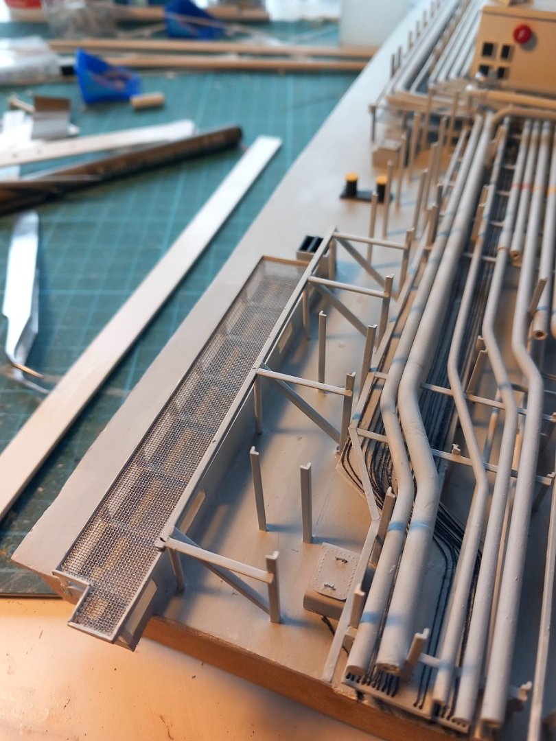
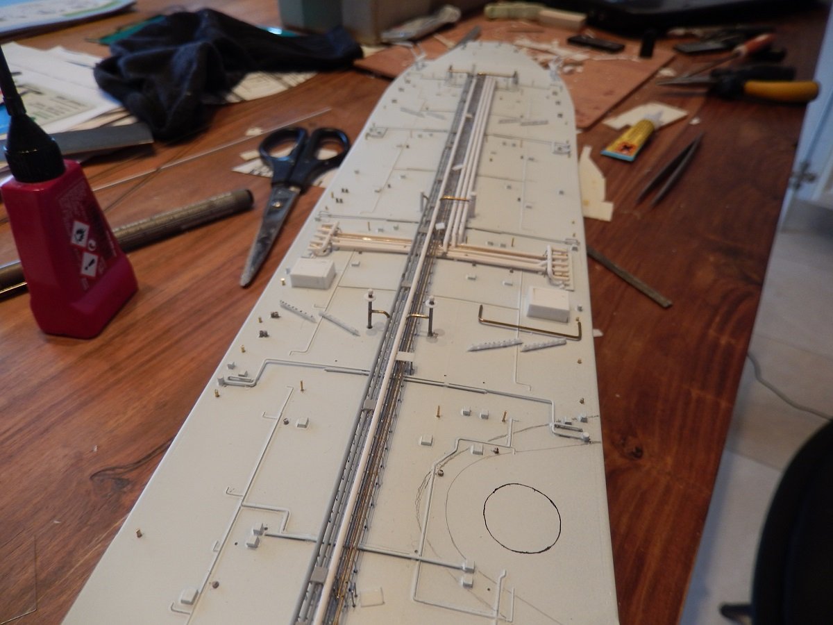
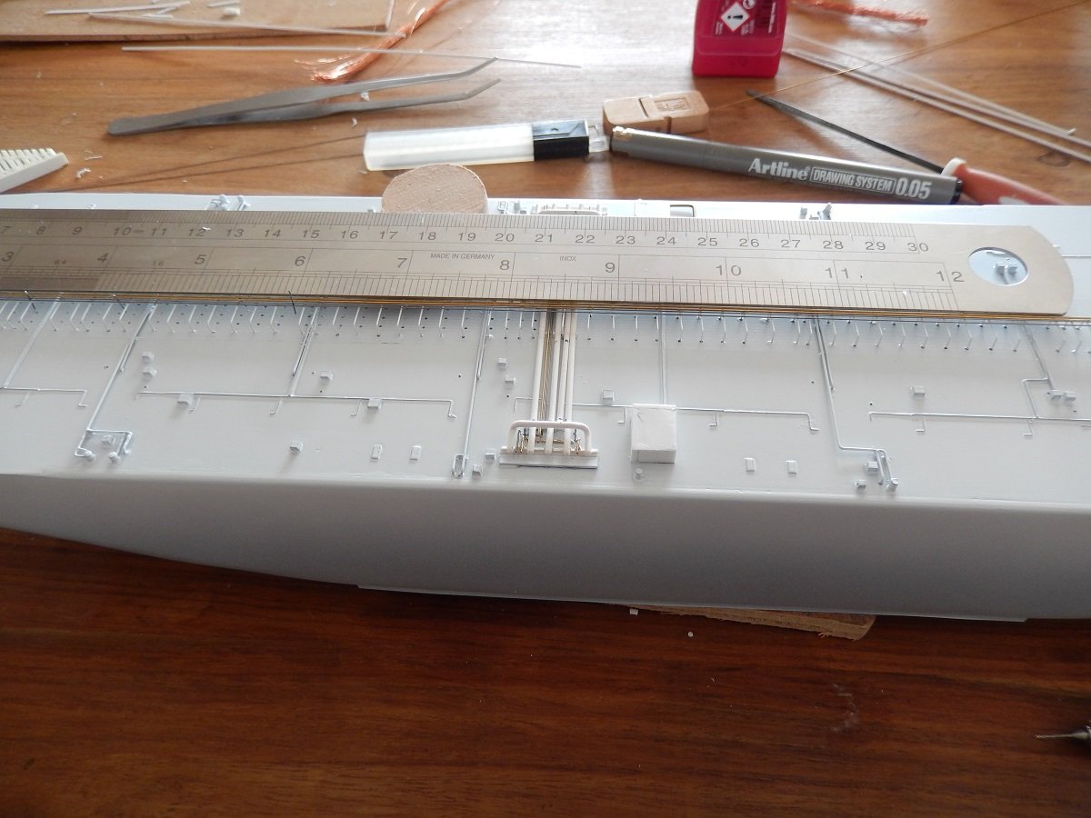
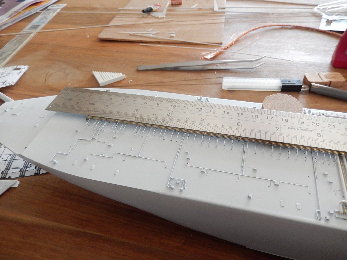
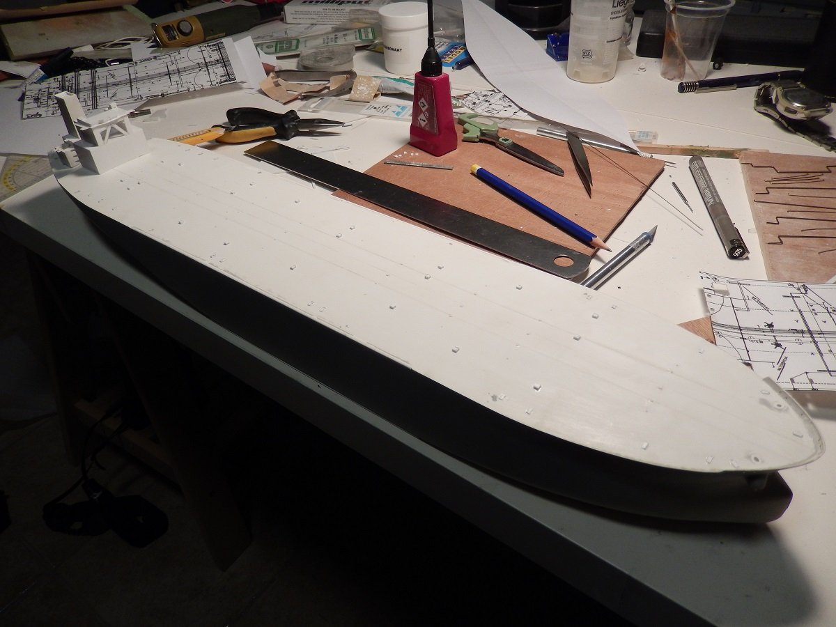
All of the above was in preparation for the first coats of paint. If I'd continue with the next layers up, they would likely cause shadow areas during spraying. First came a coat or 2 of grey primer. Working with white top coats makes it extremely important to remove any contrasts below the paint. Pencil marks are notably difficult to get covered with white. I therefore first use grey primer to even out all contrasts, later on followed by white top coat. Regarding the piping supports: - I drilled holes through the deck to allow for height adjustment - I made the brackets using jigs to have them all equally sized and shaped - I then inserted the first bracket, using a styrene piece inside the inverted U to determine the correct height - I then used that same piece of styrene (a long bar shape) to place the second one - Slowly going forward using that same piece of styrene, each time blocked under 2 fixed supports while mounting the next 2 supports - while doing this, I used a metal ruler to push the brackets each time down, creating a long straight line on top of the brackets in a longitudinal direction After this initial coat came the second layer of piping, pipes that aren't quite on deck, but just slightly above (taking into account the 1/700 scale of course) And then came the typical long longitudinal pipes. Again I used the metal ruler to keep things straight. Over such long lengths, 0.3mm and 0.5mm wires have a tendency to bend. While moving to each next pipe, I used small spacers with a diameter depending on the actual spaces. In the above and below picture you can make out some 0.3mm wire in vertical position between the last longitudinal wire and the one-but-last one. These spacers were of course removed afterwards.
-
Agreed with the others on that penguin, all by itself it also immediately defines on which hemispere and pole your diorama is located, even to people that don't know the background. I indeed hadn't thought about the creeping of the epoxy. I really can't think of any way to stop or prevent that. The only thing I could think of is treat the edges/waterlines of objects with vaseline or something else, not-solid. Perhaps the epoxy wouldn't get hold of it that way? Not sure if they wouldn't chemically interact though.
- 105 replies
-
- 5
-
-
- Ghost Ship
- Jenny
- (and 2 more)
-
Turns out a real eye-catcher Bob. Great build and I truly love those sails. The color "scheme" of your hull is also gorgeous, love the tones of the wood mixed with the black and white, resulting in an overall balanced look. 👍
-
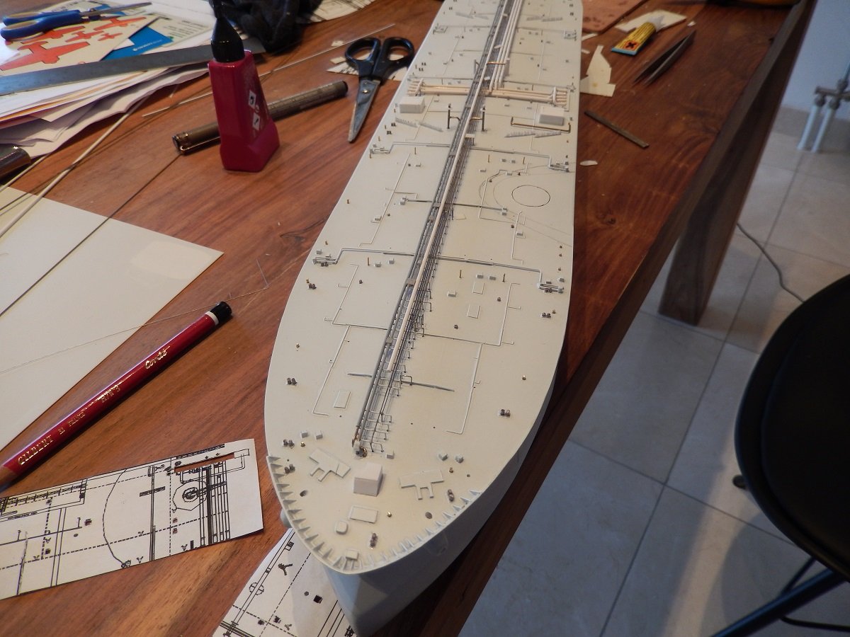
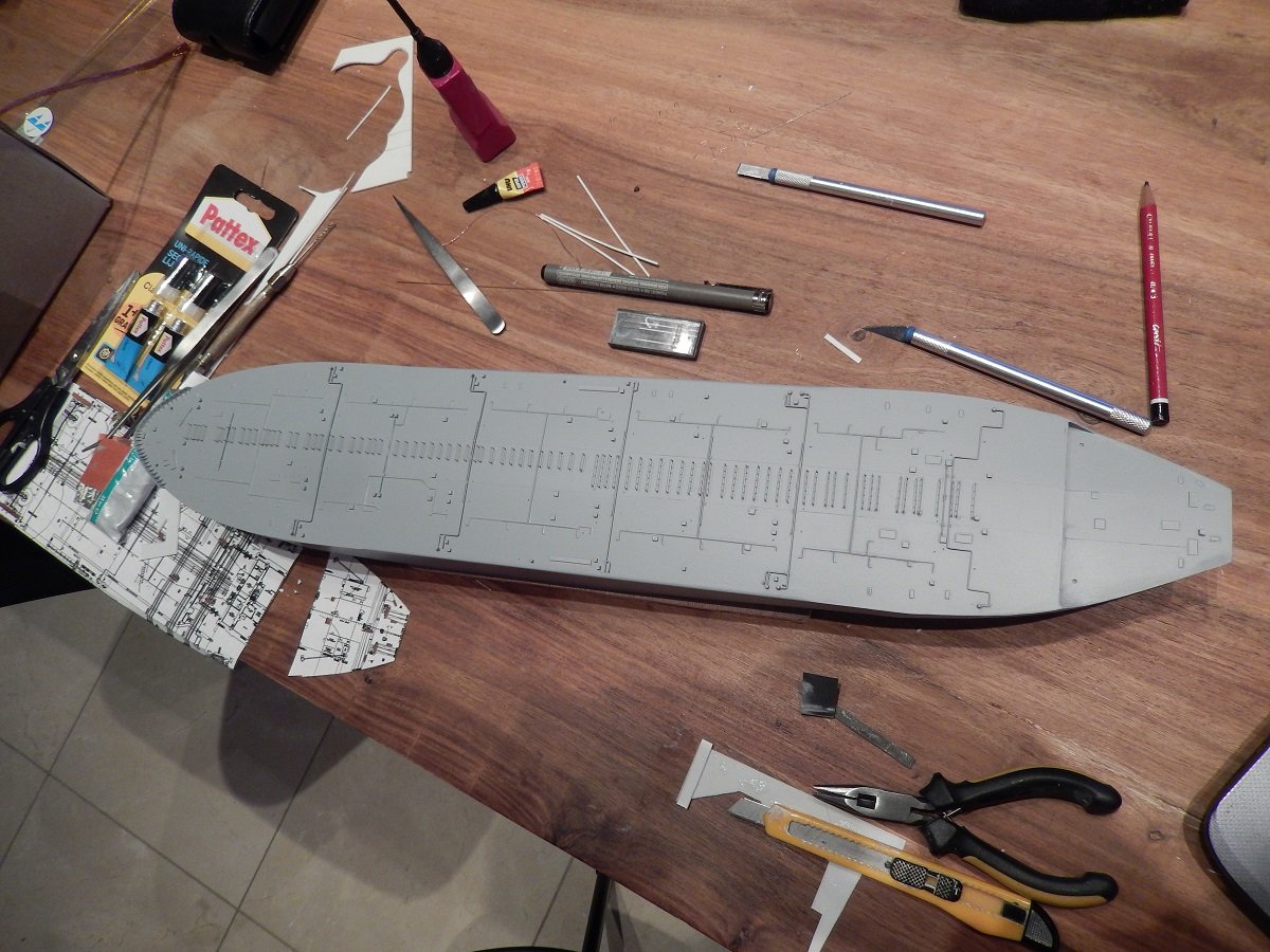
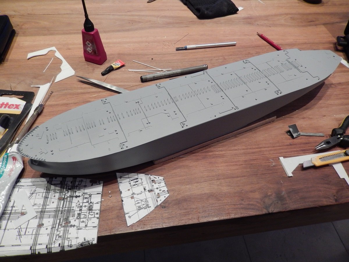
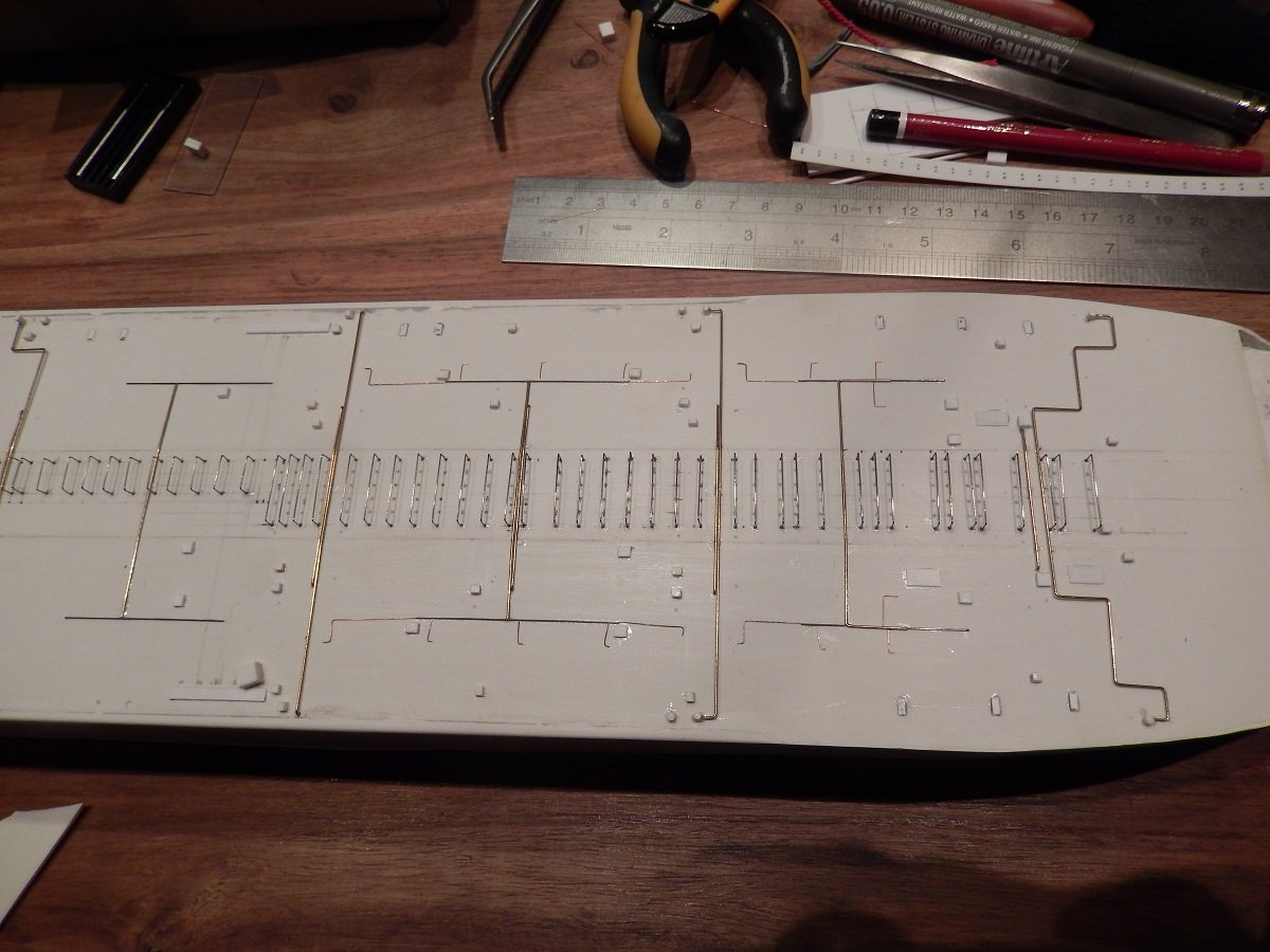
So, as crazy as it seems, this ship has little detailing to it, probably the reason why I loved building it. I love building hulls, but I sort of hate detailing (although I do torture myself by adding as much detail as possible to any build). So this subject was great for me. Oil tankers are quite simply in construction with only few different pipes on deck. First I started with some fixed points as I usually do a bottom-up approach towards detailing of tankers. These fixed points were all cargo and ballast tank entry hatches. These particular ships however had something extra. Any tanker is equipped with an inert gas plant, a plant that produces inert gas (basically exhaust gas from combustion, scrubbed with water to remove contaminants), which is used to lower the oxygen content in the cargo tanks to avoid explosions/ignitions. On gas tankers it's normally only used to prepare for dry dock or after dry dock/repairs. On oil tankers however it is continuously used to top-up/maintain cargo tank pressures. On these 4 sisters however they thought of something new. Considering the large surfaces of ballast tanks, they thought of reducing the oxygen level in the ballast tanks as well, using the inert gas plant... This meant of course that the ballast tanks also could be sealed from the atmosphere with a sort of pressure control (including vent valves to avoid over pressure). This reduction in oxygen level should then prevent corrosion and reduce the need to maintain the coating of the ballast tanks. This resulted in pipes running from the central inert gas line towards each ballast tank. These lines unfortunately made the use of bicycles (normal on such large oil tankers) very difficult, and therefore it was not done. Two deck houses were also present, which is also a very usual feature of such tankers. Close to the manifold, containing oil spill equipment as well as other things used on deck (transfer baskets etc.), since the cranes also rest on those houses. All of it was basically dry-fitted to allow me to draw out the outlines of the longitudinal piping supports. Slowly she received more pipes. In this case the Crude Oil Washing (COW) pipes, which are connected to small rotating washing machines that hang on the top of the tank. Crude Oil (=cargo) is pumped through these at certain pressures, which in turn makes the machines spin in certain cycles. The crude is then sprayed against the walls of the tank to mechanically wash off any residues of the cargo. Additionally the sprayed crude acts also as a detergent that absorbs some of that residue that is then being collected down in the tank to be pumped out. The pipes can be recognized by their transverse central pipes branching off to longitudinal pipes that connect the washing machines (spread around the tanks to fully cover the tank top/walls and bottom. The helicopter deck is also outlined in pencil. The helo deck was strengthened to take on the landing of a Sea King or similar sized helicopter. This is not too common as in most cases there is only a hover place/winching area or a helo deck for light helicopters that are used by pilots to board the vessel offshore. The central piping supports are made out of 0.3mm stainless steel wire, bent over a jig. The COW lines are a combination of 0.5mm brass, 0.3mm steel and 0.1mm copper wire. They are glued directly to the deck since this is 1/700, so the 10cm clearance between the deck and piping wouldn't really be visible.

-
But why did you put clay blobs in your bottle? I was thinking though, in real life, the largest part of an iceberg is below the surface... Do you consider adding another layer of epoxy/water to submerge part of you icebergs? Or is too late in the build to consider that? Love what you did with the ship. Difficult not to overdo the ice effects, but you clearly managed to make it work.
- 105 replies
-
- 5
-
-
-
- Ghost Ship
- Jenny
- (and 2 more)
-
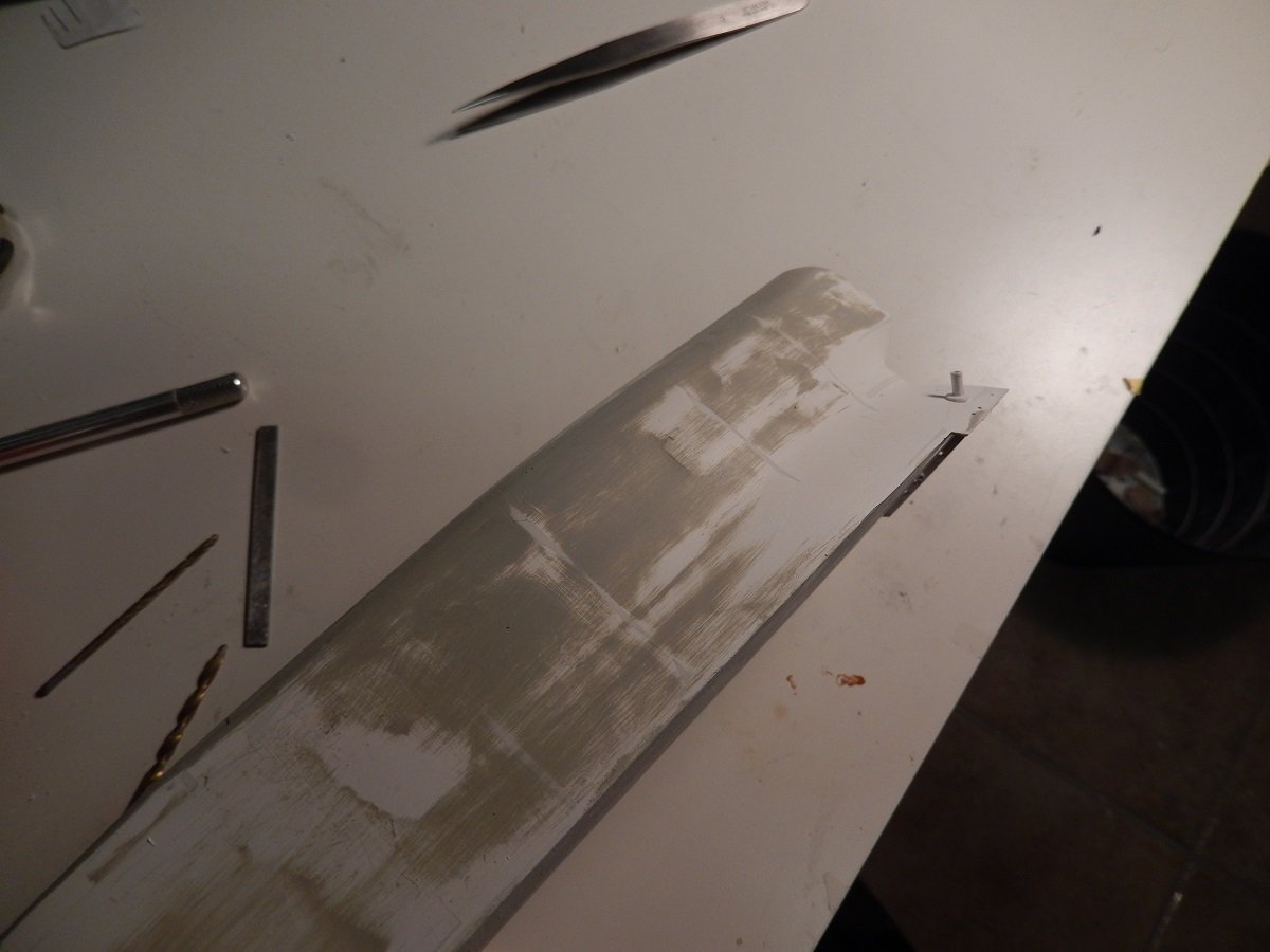
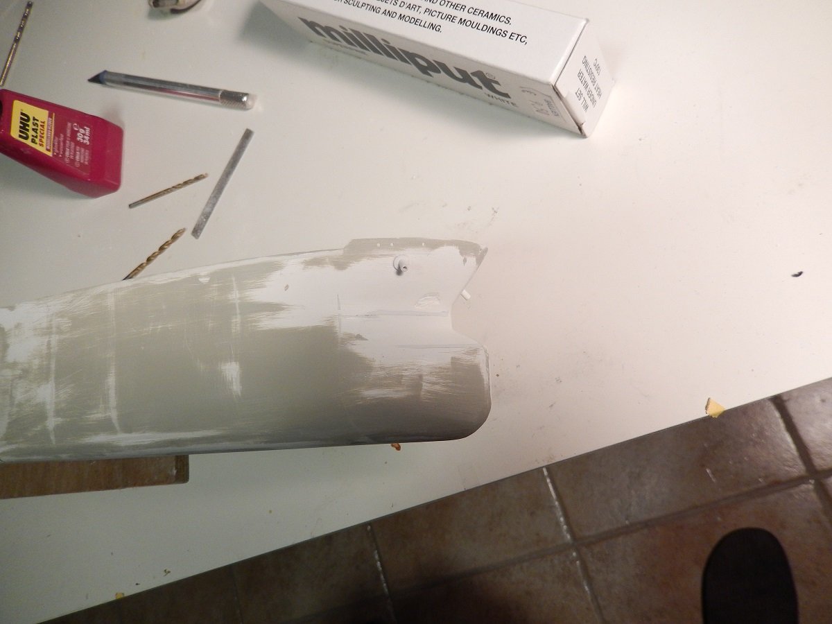
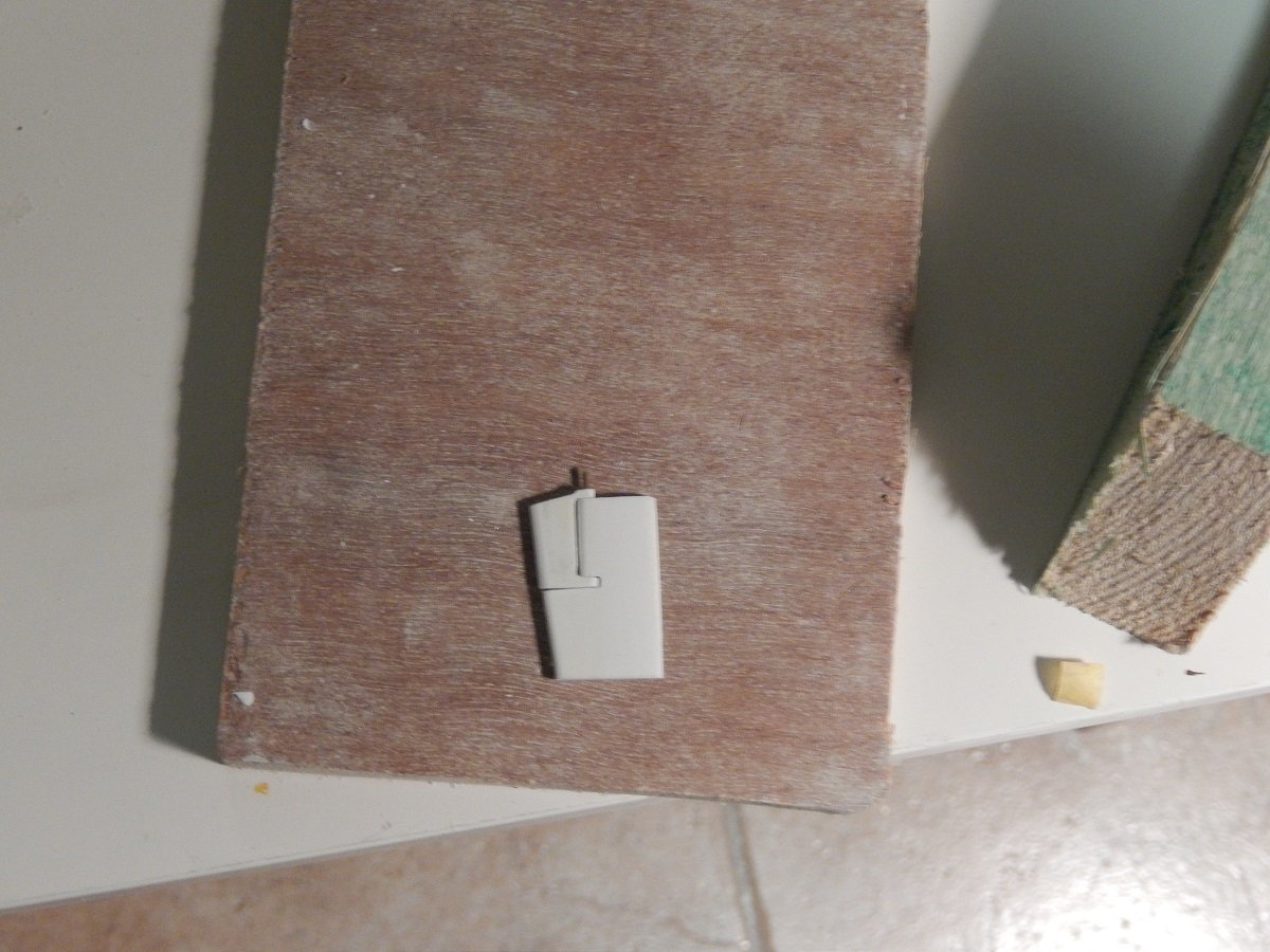
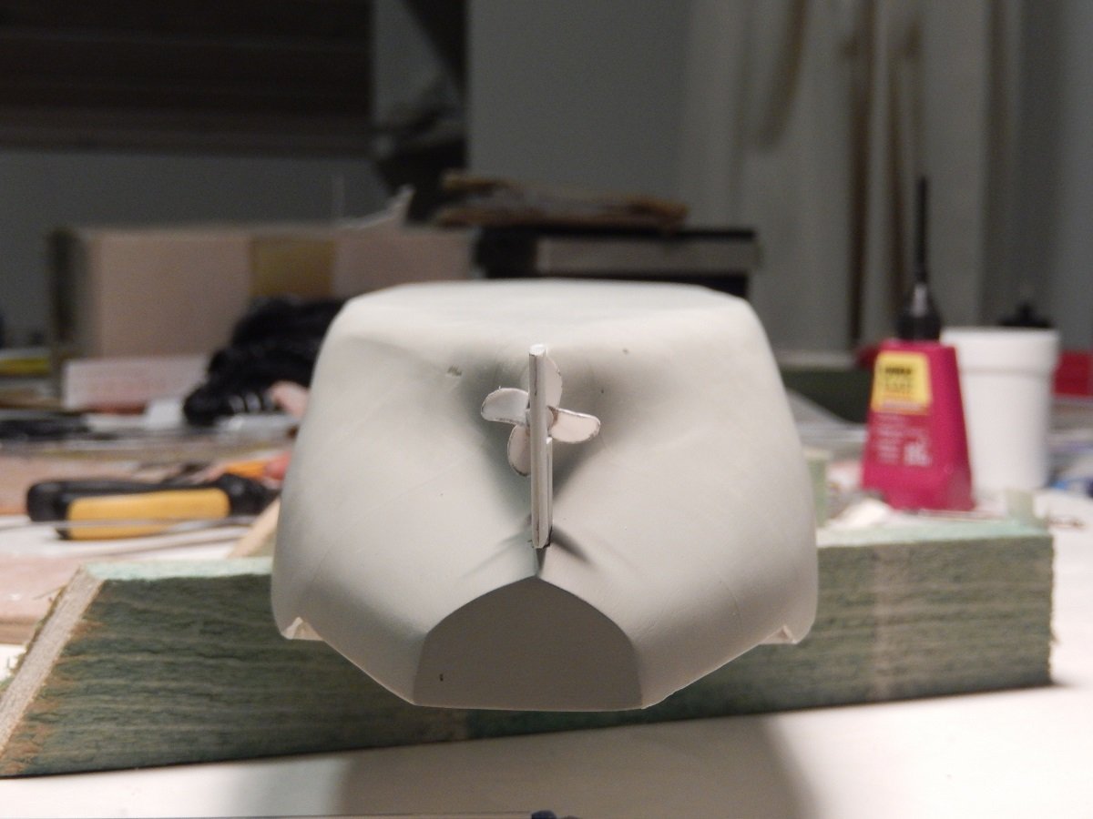
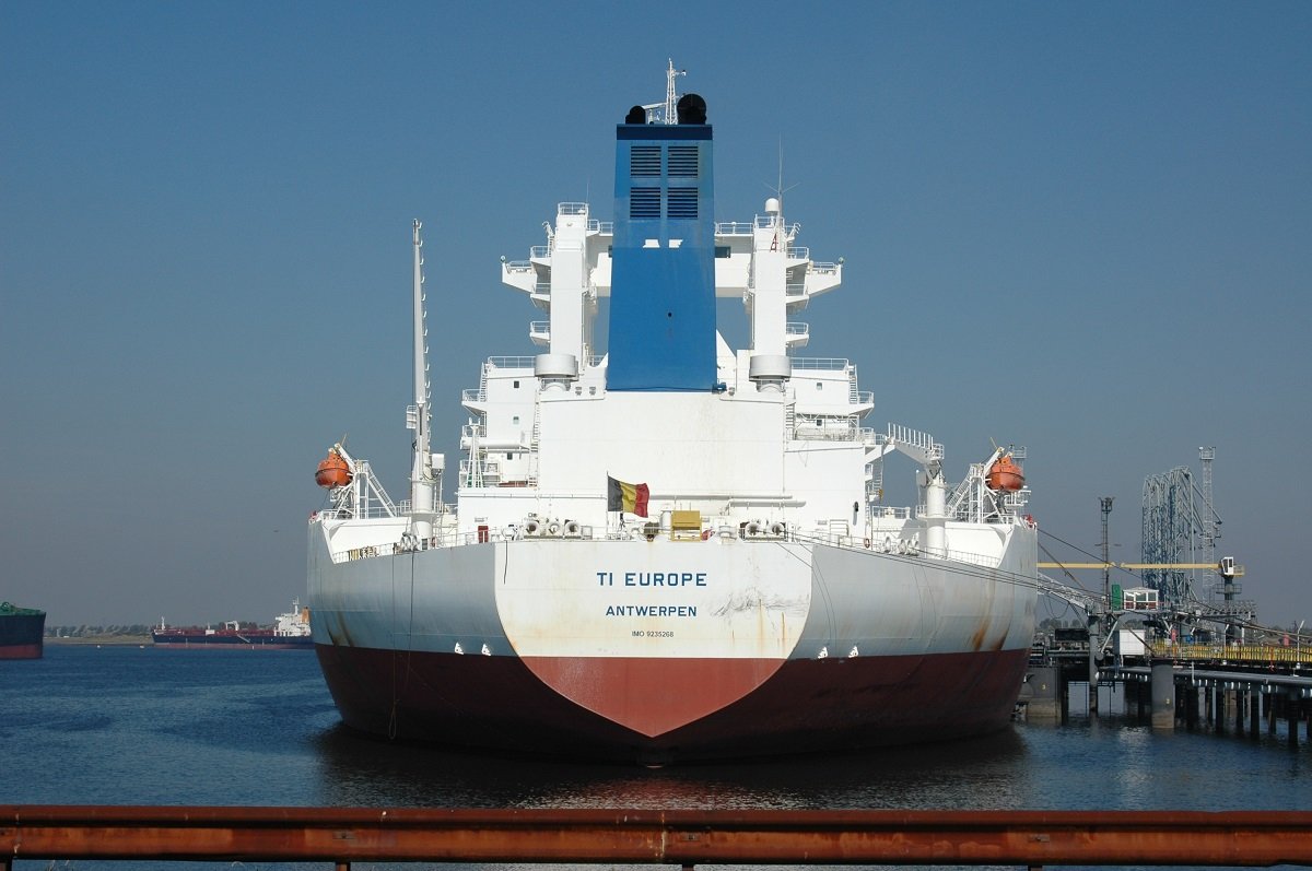
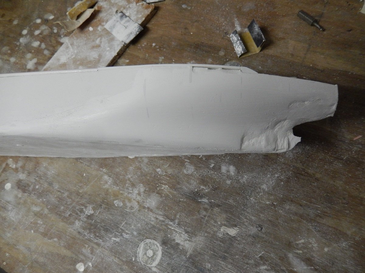
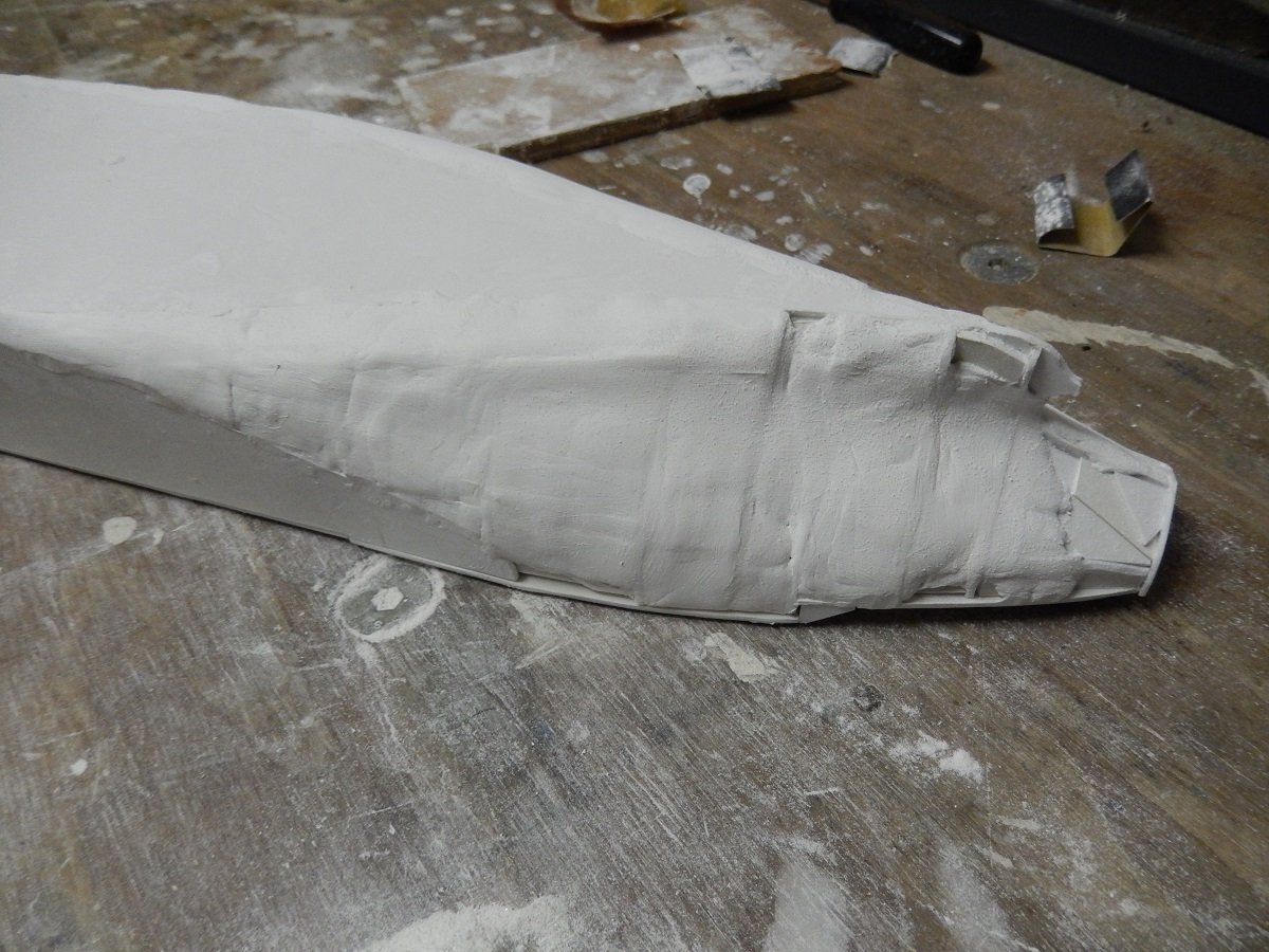
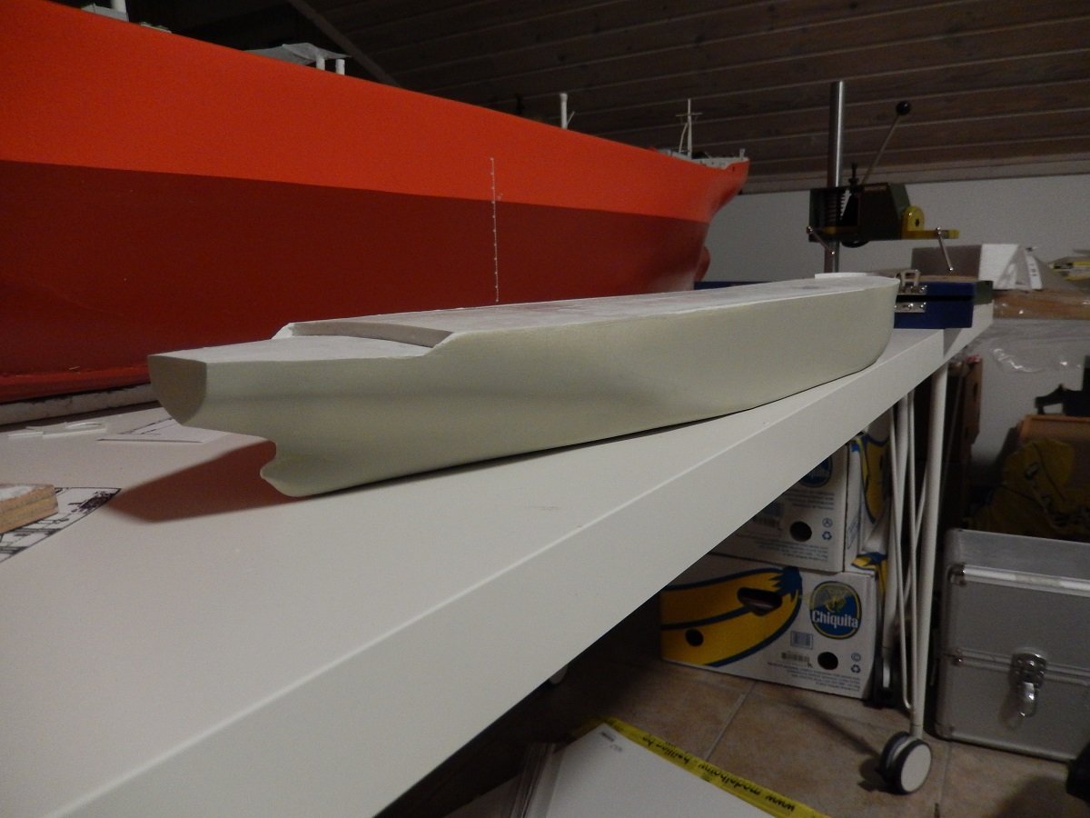
Next step is actually sanding off that filler/primer again to show where the bad spots are. It happens from time to time that there is a spot where the 2 components haven't mixed well and soft spots appear. In this case it's not very surprising that this happened due to the large amount of filler needed. If I encounter such a spot, I immediately see it when I'm sanding and I scrape it out with a knife until I hit hard edges. I then refill it with a smaller and better mixed amount of filler. On below picture you see such soft spot just on starboard of the stem, here I already removed some of the bad mixture. In following picture you see a spot where not enough filler was applied and a "hollow" was present in front of a frame. It shows immediately by keeping the dark colour of the primer/spray filler and getting a rather sharp outline. So extra filler was applied. and sanded smooth again. In the above pics you can also see the start of the "warts" for the anchors. To keep the anchors from hitting the rather large bulbous bow, the hawse pipes extend beyond that bow. A lot of work for a hull, but since the build is 90% hull, it should also look accurate. After the main hull work came the rudder and prop. I made the prop of 0.3mm styrene. Luckily it's a gigantic propeller in real life, so making a model of it still results in a decent size propeller (same in fact for the rudder). And a picture of the real backside of the vessel during one of her rare actual port calls. You can see how wide she is by looking at those lifeboats and the distance between them...
-
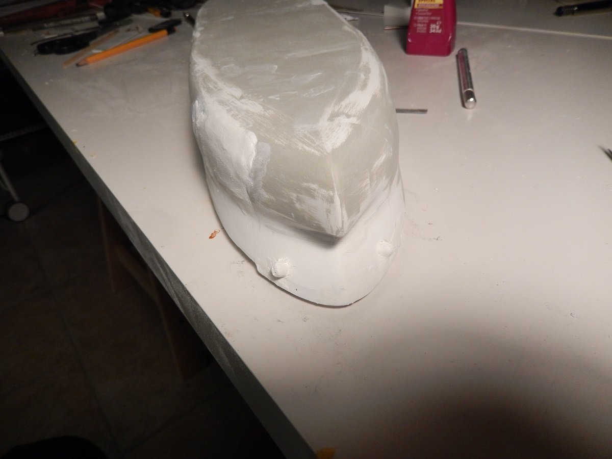
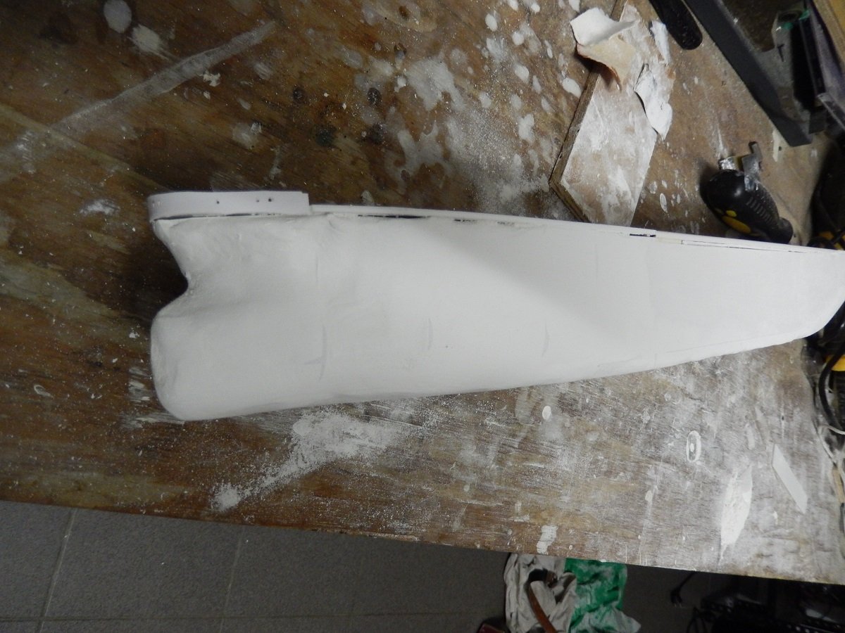
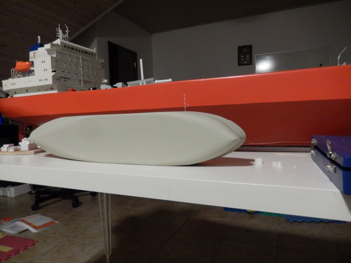
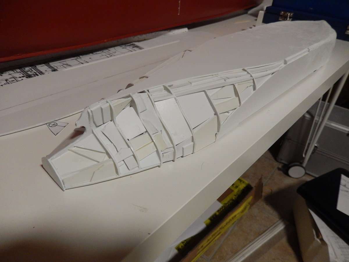
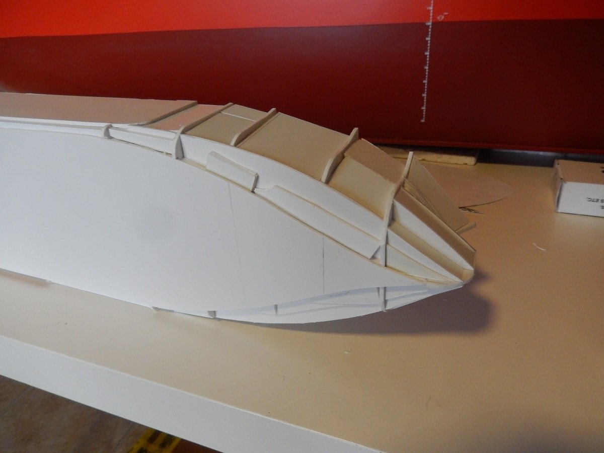
Thanks Glen, have no fear, I have obtained quite a collection of interesting bottles nowadays, each one screaming for me to put something inside. 3 of them actually have a very long body with a short neck, ideal for putting and manipulating a ship inside. I've been making plans for this and one of them will likely be a sailing vessel, following your lead. Next phase of this build was the filler. After many builds I've given up on trying to do this in 1 go. It's a dirty job, mixing the epoxy filler and applying it, so I'm always postponing this and trying to do it in 1 time, mixing decent amount of filler. However after sanding, I always end up with spaces requiring more filler... In any case, here was the first coat of filler pressed on and around the frames. And after a first rough sanding, to determine where more filler will be needed. And the white blob slowly starts to look like a ship. And after more filler, I decided to get going with spray filler. Something I had used on one build before, but that has become a standard practice on my builds by now. It fills up small gaps etc. while making any deficiencies pop out and it allows for smooth sanding. In this build it also showed some areas that needed improvement, so it was definitely not ready yet. It did start to show the typical voluminous tanker shape.
-
So much effort in that ensign, but the result is fabulous. The structure really appears a fabric rather than simply paper or plastic.
-
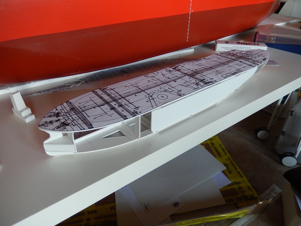
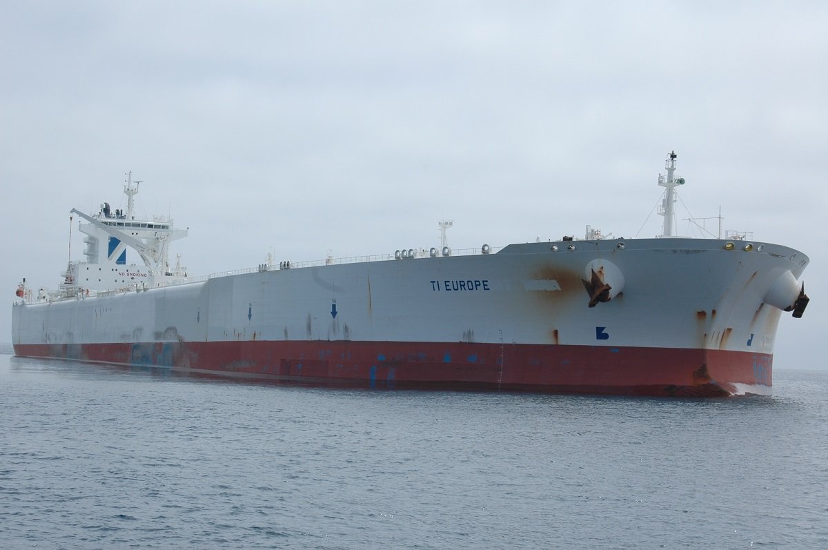
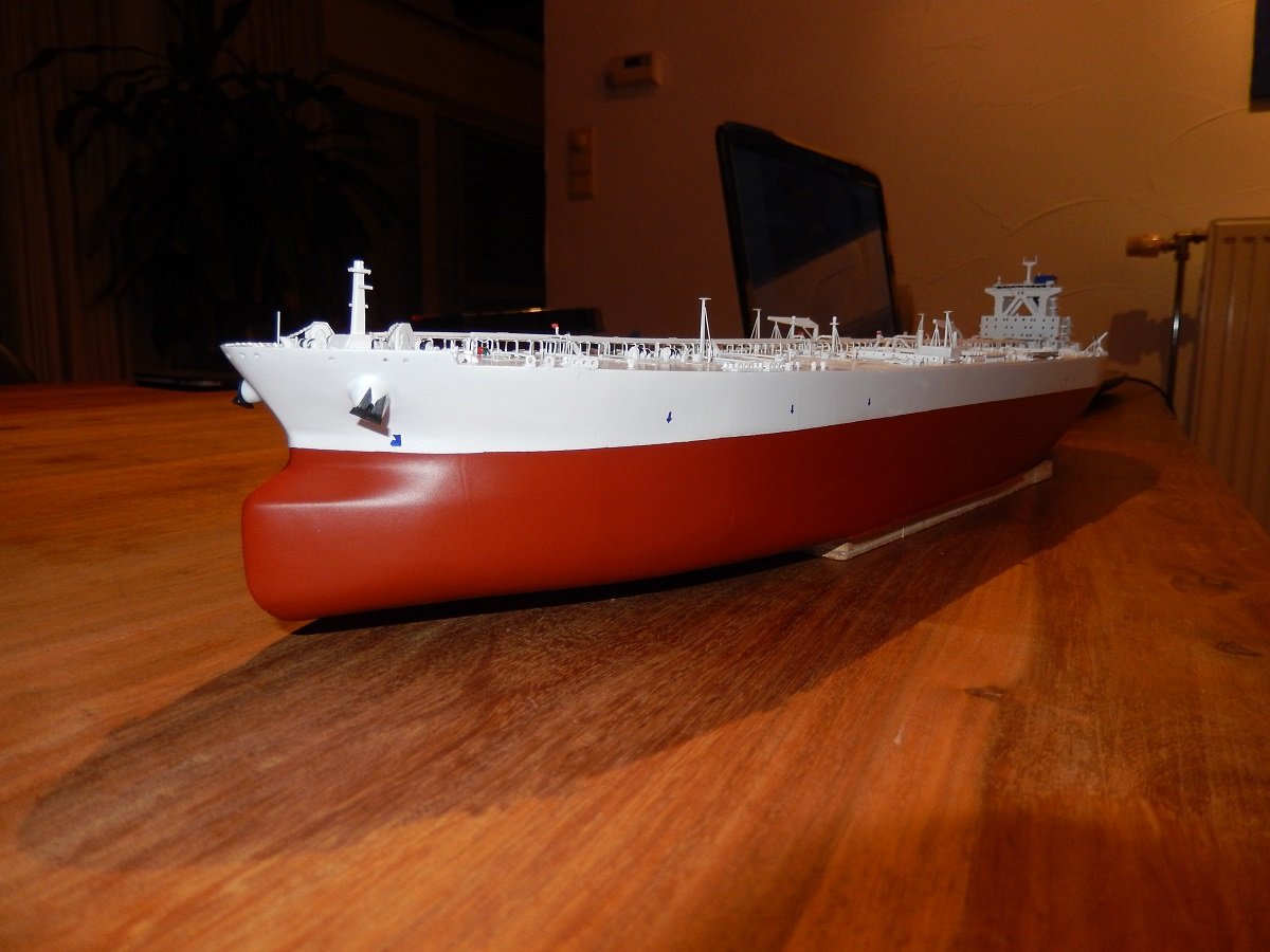
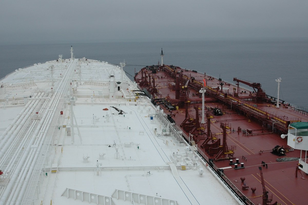
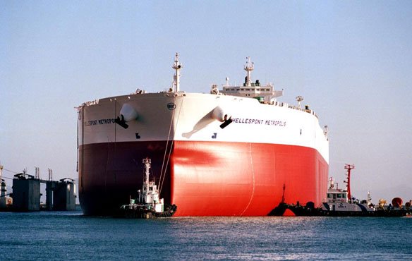
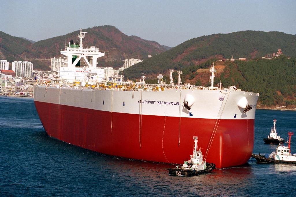
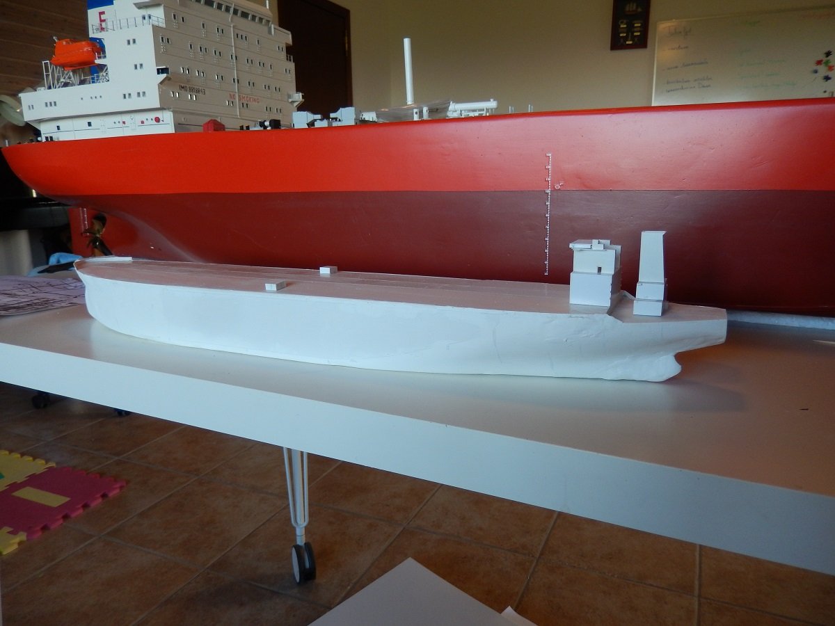
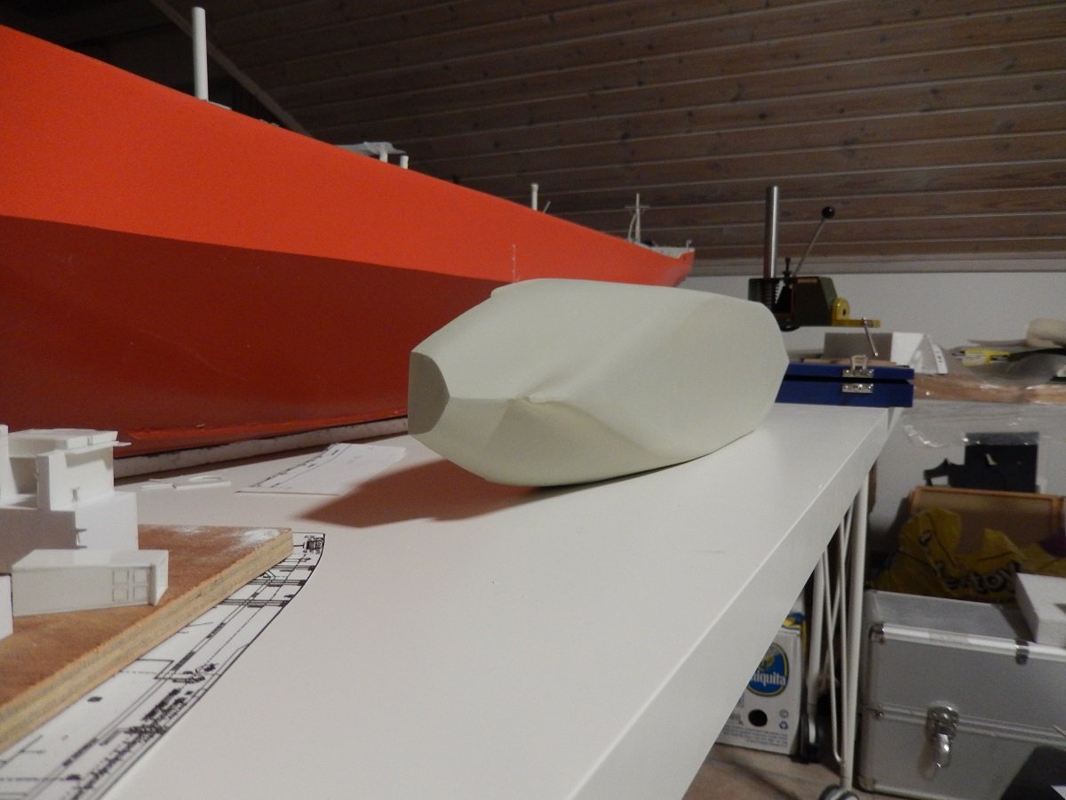
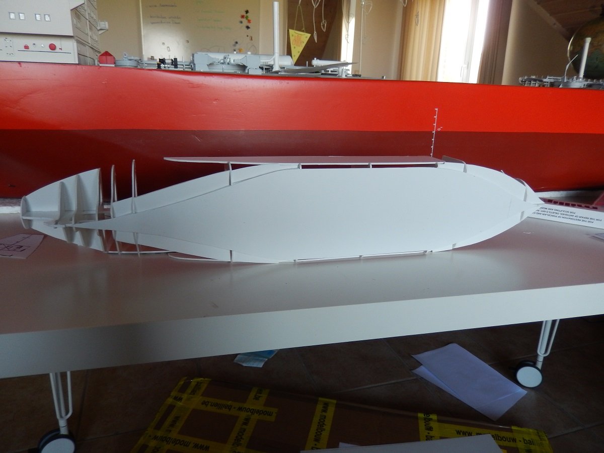
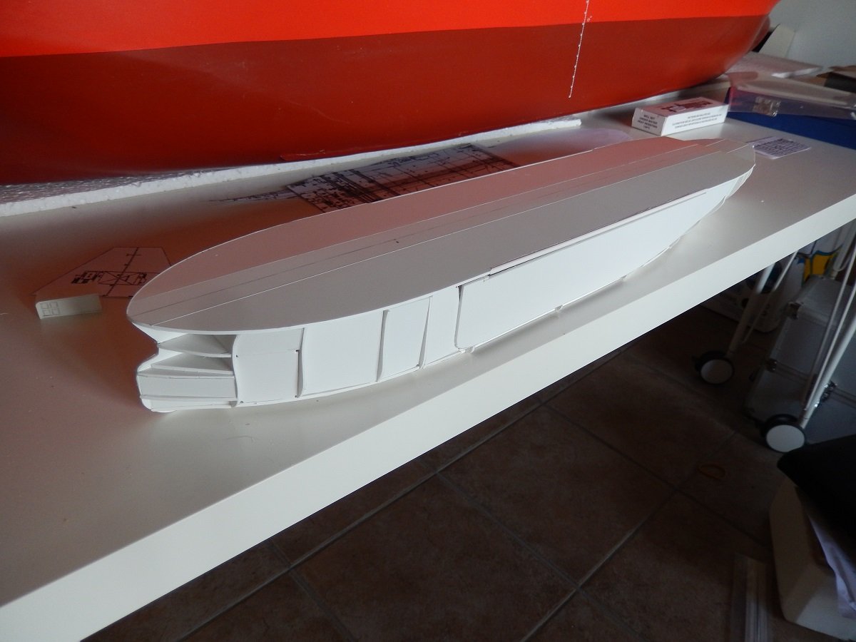
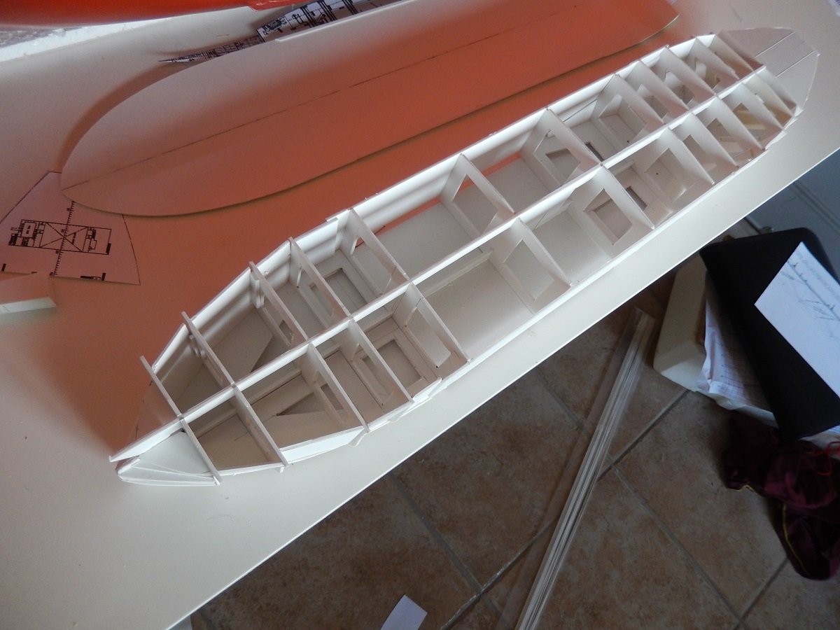
Great to see more models of these ships. I see the one in your picture is TI Africa, which I believe now is known as FSO (Floating Storage and Offloading) Africa. As you can also see in these vessels they don't have the regular huge bridge wings like VLCC's. Due to the presence of camera's around the vessel, she received an exemption of these bridge wings (used to look along the vessel during mooring and sailing). You can also see the big gap in the accommodation, the crew is quite small on tankers nowadays, yet there is a rule for view from the bridge towards the bow, you need to see any vessel/object passing 500m (or 2 ship's lengths, whichever is the smallest) in front of you. This means that for a big ship like this, the bridge needs to be quite high up, resulting in a pretty big accommodation. Since there was no need for a large accommodation, they made that gap in the superstructure, to both have a high bridge, but still limit the amount of internal accommodation space. One of the legs of that bridge houses a staircase, while the other side houses an elevator. Back to the model. I continued adding the frames and outlines, including the bottom plate. You can also clearly see that the stern is a lot more sleek and slender than the bow below the waterline. This is actually the case for most merchant ships, but it's not always this pronounced. I normally use this method of construction for smaller ships, but on such a large vessel, filling in the space between the frames is even more important before applying any filler. On smaller vessels I use mostly scrap pieces of styrene that I cut some angles off etc. Kind of like a jigsaw of scraps. This helps to avoid large amounts of filler. In this case I did actually cut pieces of styrene from a new sheet to fill most of the space near the bow. For the stern, I did use more scrap from my scrap box. Since the two component epoxy filler I use is rather difficult to manipulate, I used some reinforcements on the edges of those filler plates to avoid them being pushed in when I apply the filler. This happened sometimes in the past, when my scrap pieces were not well fitting for the space they occupied. I don't care too much about having a perfect match, small holes and gaps will be filled by the filler after all. You do however need some gluing surface if you want it to be sturdy enough to push the filler around.
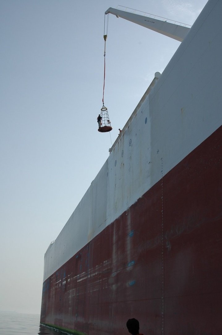
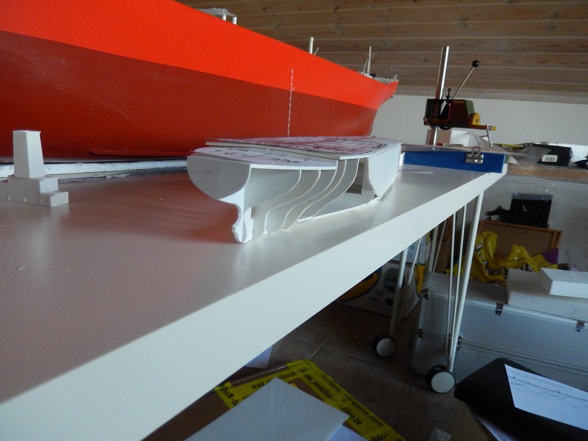
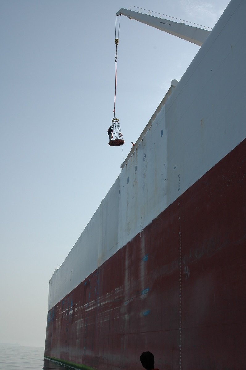
-
In my haste yesterday, I forgot to add a couple of pics of the real thing. So here we go. When you see it in loaded condition from a distance, it looks rather flat and not so big, but once you get closer, you start getting an idea. It's ok right? Until you realise those orange dots on the starboard side midship and forward are actually people. You can also see the small hiding shelters amidship and the big wavebreakers on the deck. Those hiding places are necessary as it takes a long time to get from forward to the accommodation block. In ballast condition, disembarking is not for the faint hearted. So why the white? Well, we used to say, hospitals are white too, to keep the patients calm... But the real explanation is that the color was chosen to reduce cargo boil-off. Oil tankers have quite a reduction in amount of cargo due to boiling off of the lighter elements in their cargo. Pressure inside the cargo tanks starts to rise because of that and eventually it blows off through overpressure vents. Over such a large surface/structure, the colour actually did make a difference, probably also the reason why it was never changed, eventhough the ships changed hands several times. They were actually built too late. The heyday of oil tankers was already over by 2000. ULCC's were a thing of the past, as a cargo volume of 3.2million barrels of oil made it very expensive to load these beasts, while the amount of ports and voyages was limited. Nowadays some of the sisters are used as Floating Storage Units in oil fields, while on Europe (and perhaps Oceania) are actually used for transport. One big advantage of such subjects from a modelbuilding point of view, is the large "parallel" surface. Something most merchant ships have as it helps them to moor safely. These are often also drawn on the plans and make their box shape easier to build, only really requiring frame shapes forward and aft. I didn't actually have many plans to work from, but I combined all sorts of shapes I had from those plans. I therefore combined frames as well as floor outlines and heights to get an accurate shape.