HOLIDAY DONATION DRIVE - SUPPORT MSW - DO YOUR PART TO KEEP THIS GREAT FORUM GOING! (Only 24 donations so far out of 49,000 members - C'mon guys!)
×


Javelin
-
Posts
624 -
Joined
-
Last visited
Content Type
Profiles
Forums
Gallery
Events
Everything posted by Javelin
-
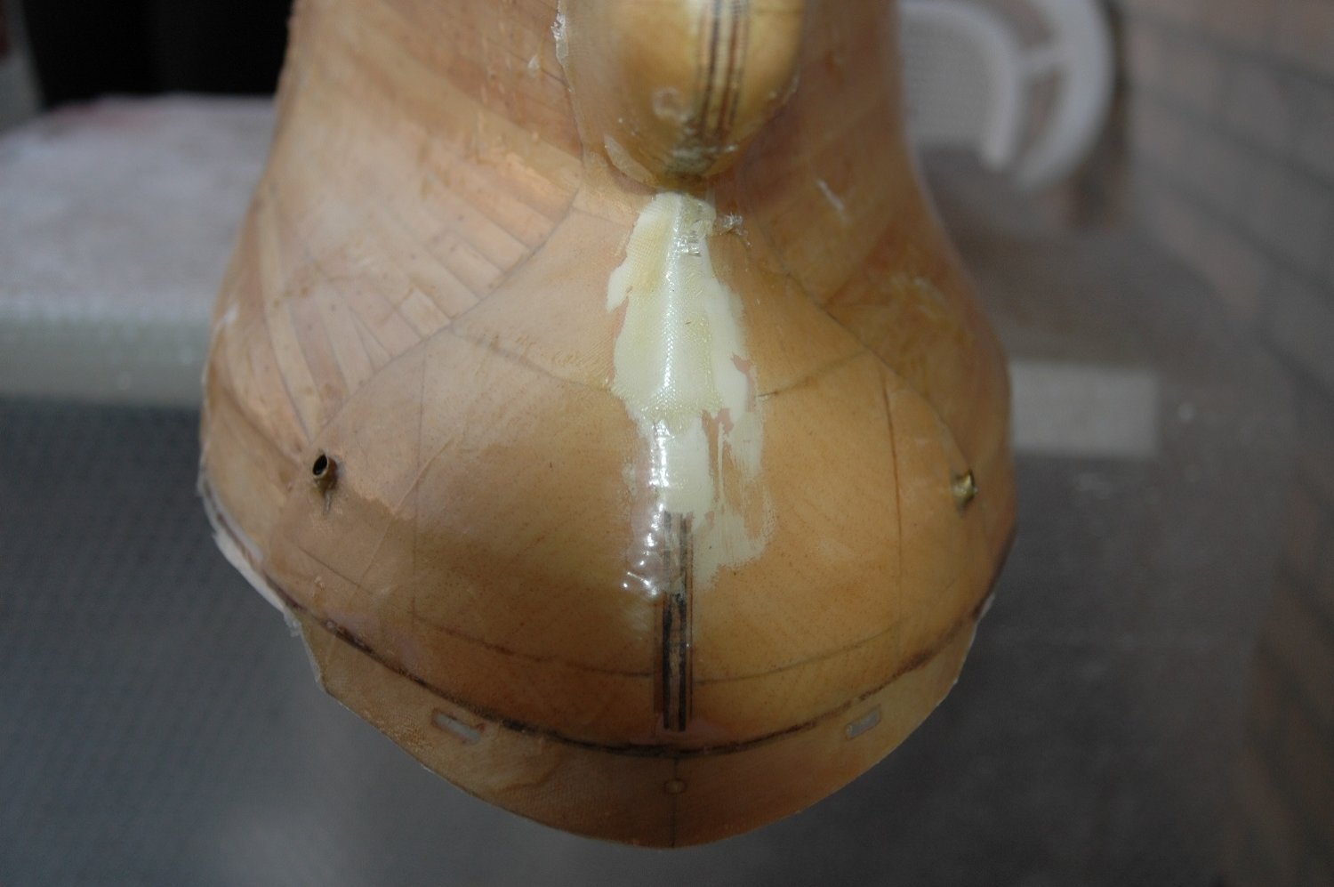
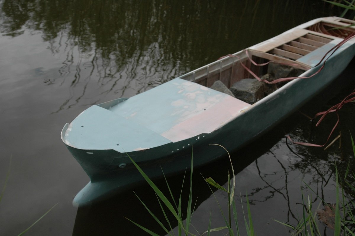
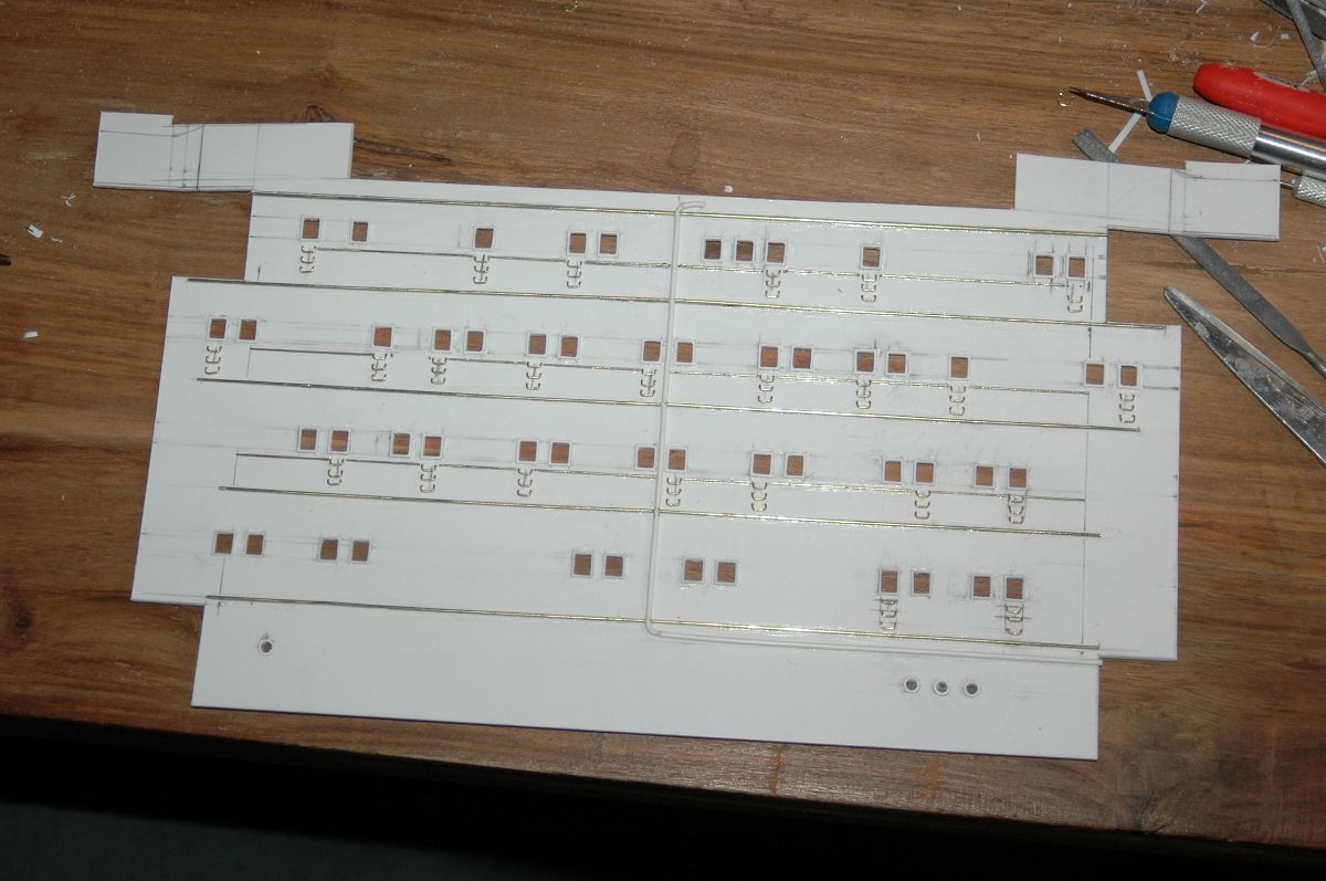
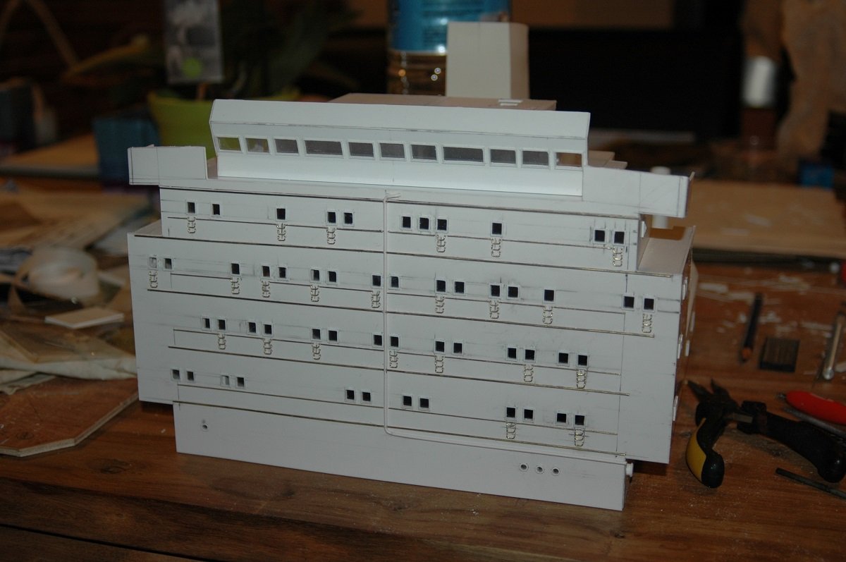
 I did read up on this before starting this whole endeavor, so I did put the cloth first. I didn't use a squeegee, not sure what I used, but when I started pushing the resin through the cloth, the edges of the cloth started raising (which is what you see in the pics), since it couldn't follow the curves of the vessel. A few extra cuts on the cloth or simply more time to push it down again would have fixed it. Instead, in this situation when I was trying to fix it, the polyester hardened (I'm talking about 5-10 minutes of working time) and since it's a big hull I was still spreading resin on the rest of the vessel when it already started hardening at the other side. That's exactly why I'd use the slower curing Epoxy next time. From here on my records are more fuzzy. I'll just show the pictures and try to keep it in a somewhat chronological order. When the hull was complete, I did a water tightness test with some stones to see if the weights needed were corresponding to the scale weight calculations. And I continued with the accommodation block. I usually wait with that for a hull to finish (also in small scale builds), because the bridge wings have to be matched with the width of the vessel. As mentioned before, I did the facing separately. You can see why... Drilling so many holes in a thick plate is not easy. They built those ships in the 80's, I guess they took in account escape routes much more than they do nowadays. The cabin windows were the escape route. There was a hammer on the inside to break the glass and then you could step out, use the small steps on the outside with the water spray system as a foothold and shuffle to the sides, where you could go down to main deck using a ladder (not on the model for now). Once that facing was finished, I mounted it in place. The large holes on the thicker plate in previous post were made to make sure the windows of the final facing would be clear.
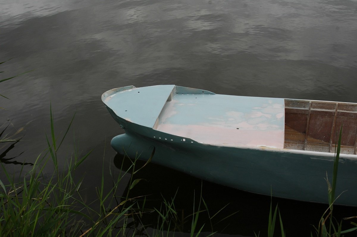
-
Brilliant work. She's already a very impressive model, even unfinished! Enjoy the break.
- 233 replies
-
- 2
-

-
- Indefatigable
- Vanguard Models
- (and 1 more)
-
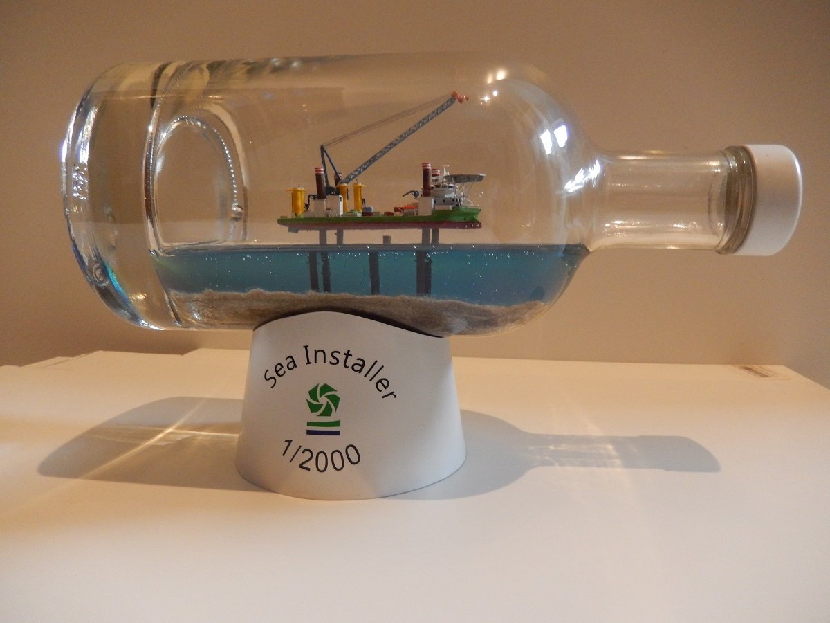
Finally gotten around to finishing this one. The cap was a bit damaged, so I gave it, along with the base, a couple of coats of spray putty, followed by a satin white coat, resembling the colour of these windmill bases. Since the cap looked somewhat like a hub, I played around with the idea of putting the 3 openings or at least base plates for the windmill blades on it, however I didn't do that. It would probably still take some attention from the ship. I decided to cut some vinyl lettering and logo for the base, since the ship itself lacks the name (of course!). It's a slimmed down version of the original idea, but I think it gives more attention to the ship itself. So I consider this build finished!
- 51 replies
-
- 12
-
-

-
- Sea Installer
- Bottle
- (and 1 more)
-
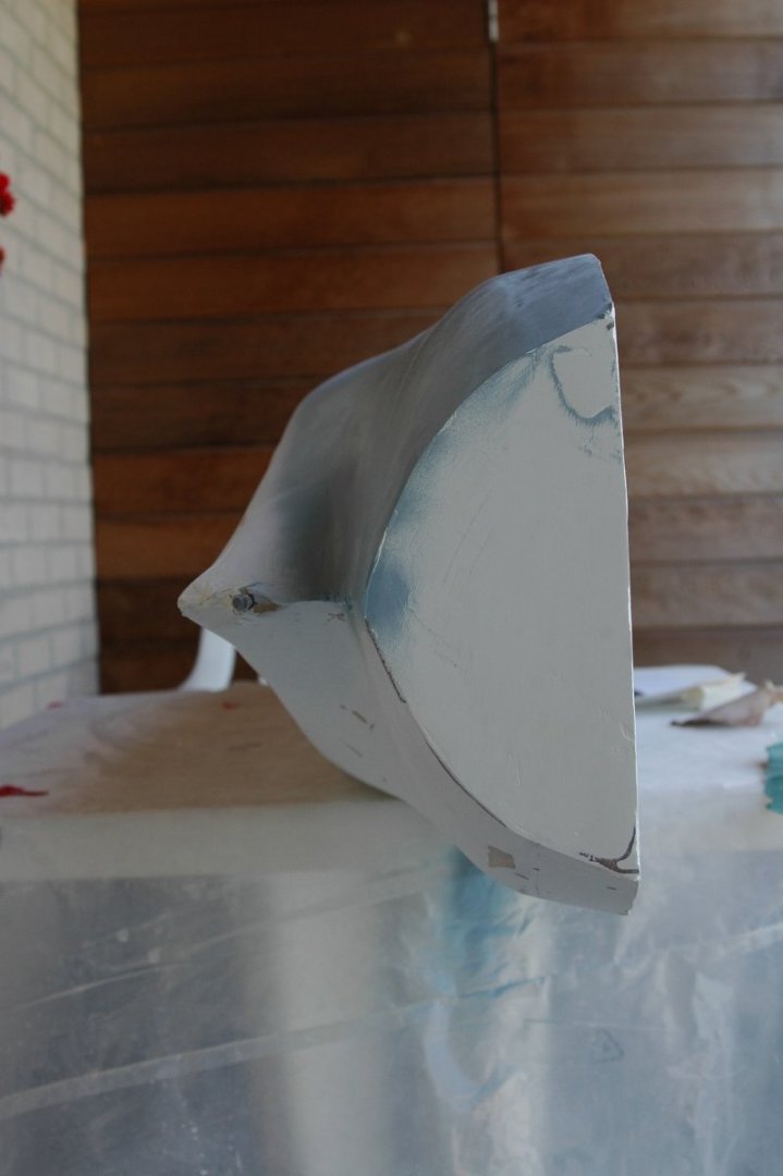
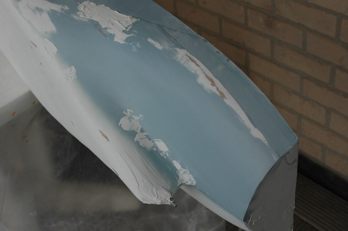
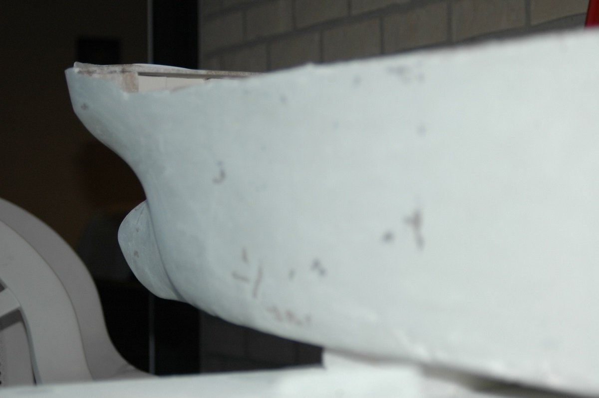
That was indeed the case Ian. All the above pics represent somewhere around 1 year of work, although I must admit it was very disturbed since I sailed 3-4 month contracts at that time. Since I was only home a couple of months a year, it was also very much weather dependent (had to be home in the right months of the year) and of course a lot of hesitation was involved since it was my first one in this scale and style. Epoxy was coming up as a modelling material at that time, but there was a lot of talk about toxicity etc. and I believe it was also a lot more expensive than polyester in those days. In any case, I'd use epoxy if I'd do this again. The slower curing is quite a requirement for this kind of job. So next is the continuation of that hull. After the first layer, I sanded it all down again and once I was more or less happy, I put a first coat of sacrificial primer. I used gray as it would show the bumps and pits better. After that I filled the pits with more putty and sanded it down again. My mistakes at that point were that I filled too little. I learned that you had to fill a larger area around the pits in order to sand it smooth with the surrounding. In any case, this was followed by another coat of primer and a series of small patches to arrive at an acceptable result. I seem to have lost some pics from that phase as well. After the body work, I placed small litho (aluminum) plates around the anchor hawse pipes, since in reality the steel plating is thicker there to protect the hull from the anchor flukes. I afterwards added the two "warts" on top of those plates, that give the anchor a good position when it is inside. And the final shape of the bow.
-
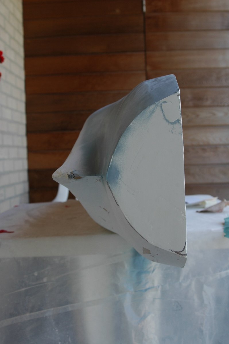
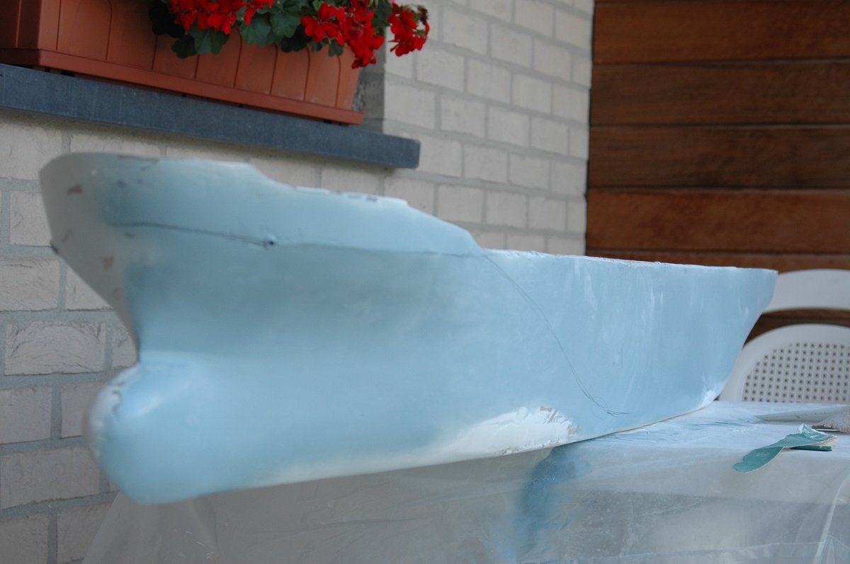
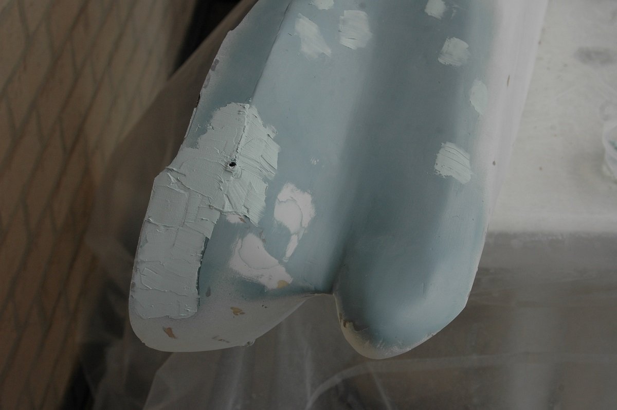
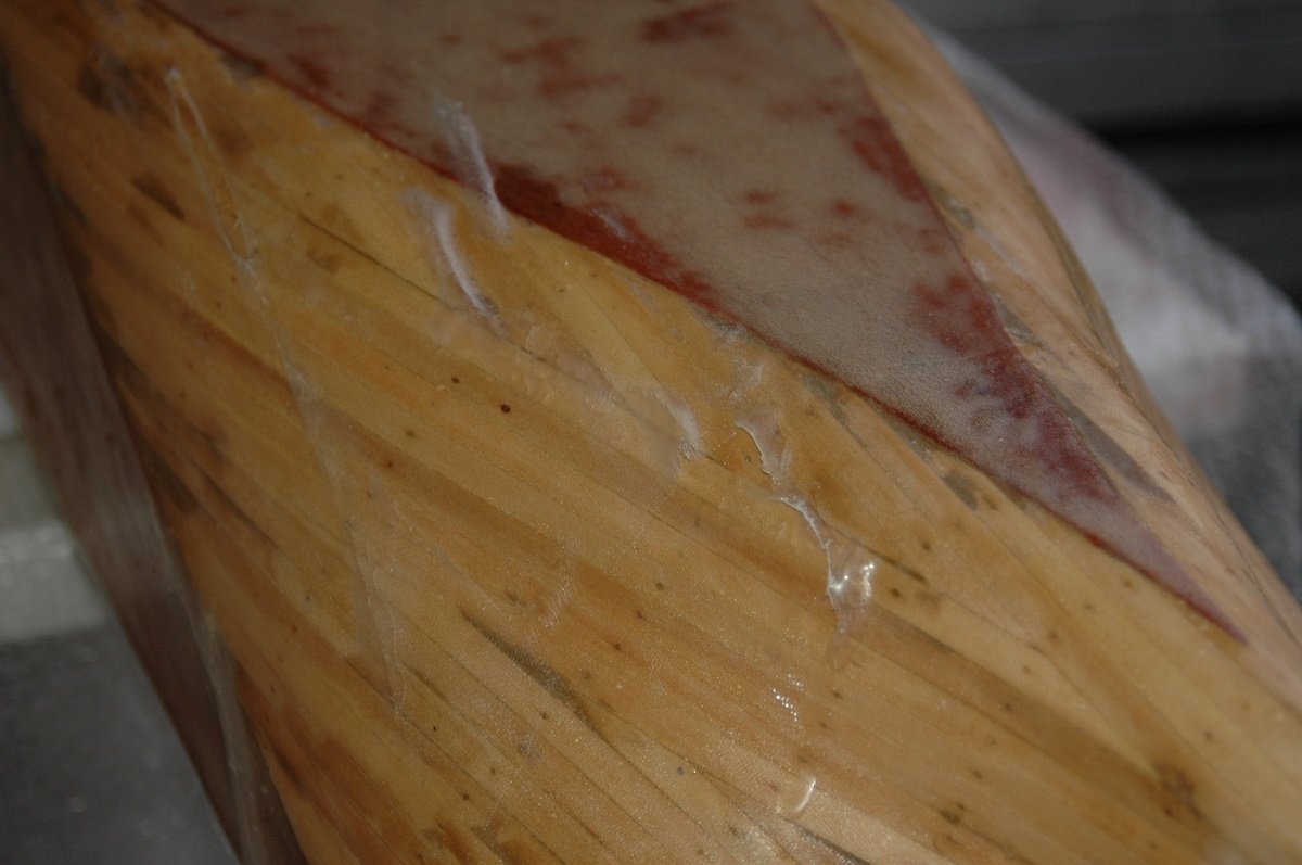
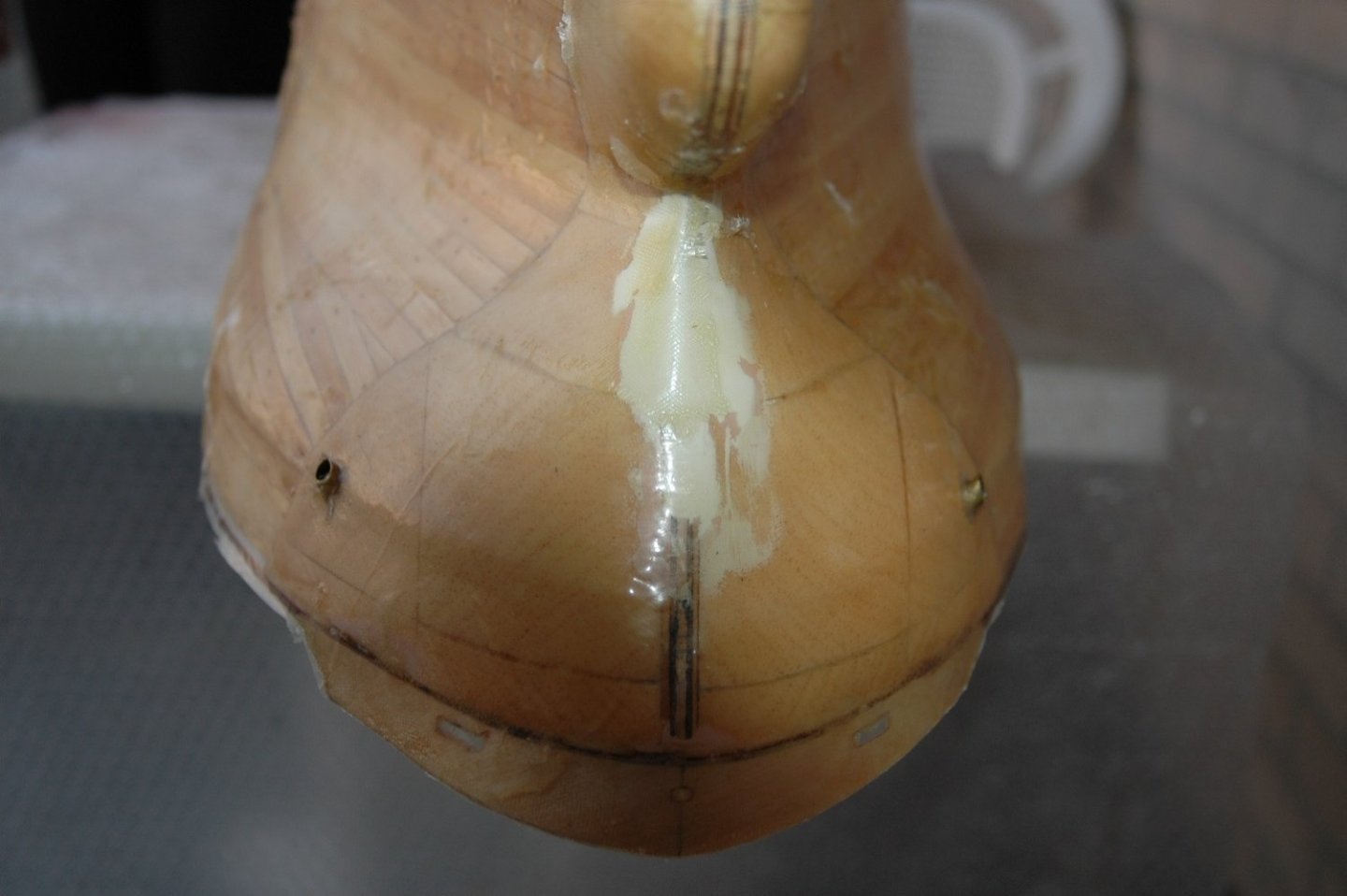
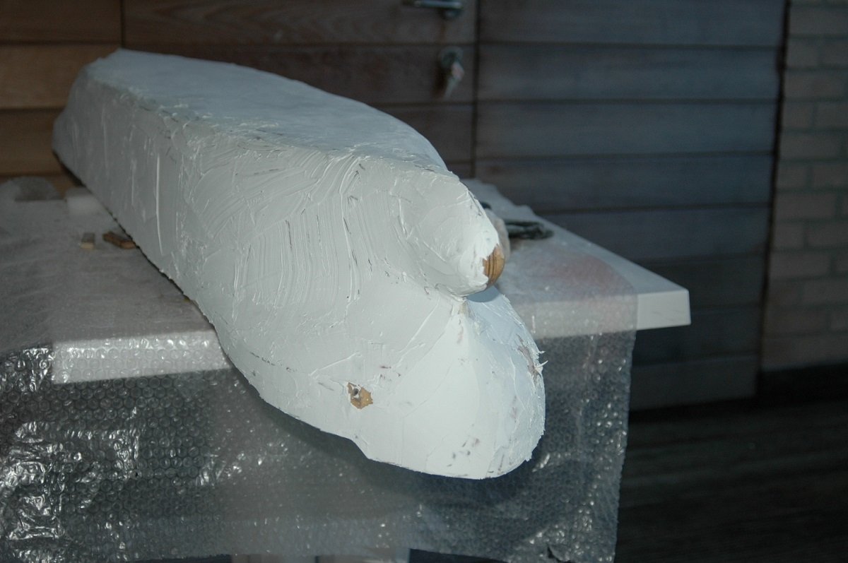
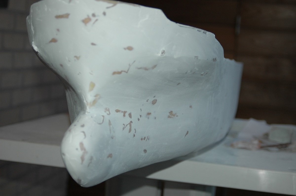
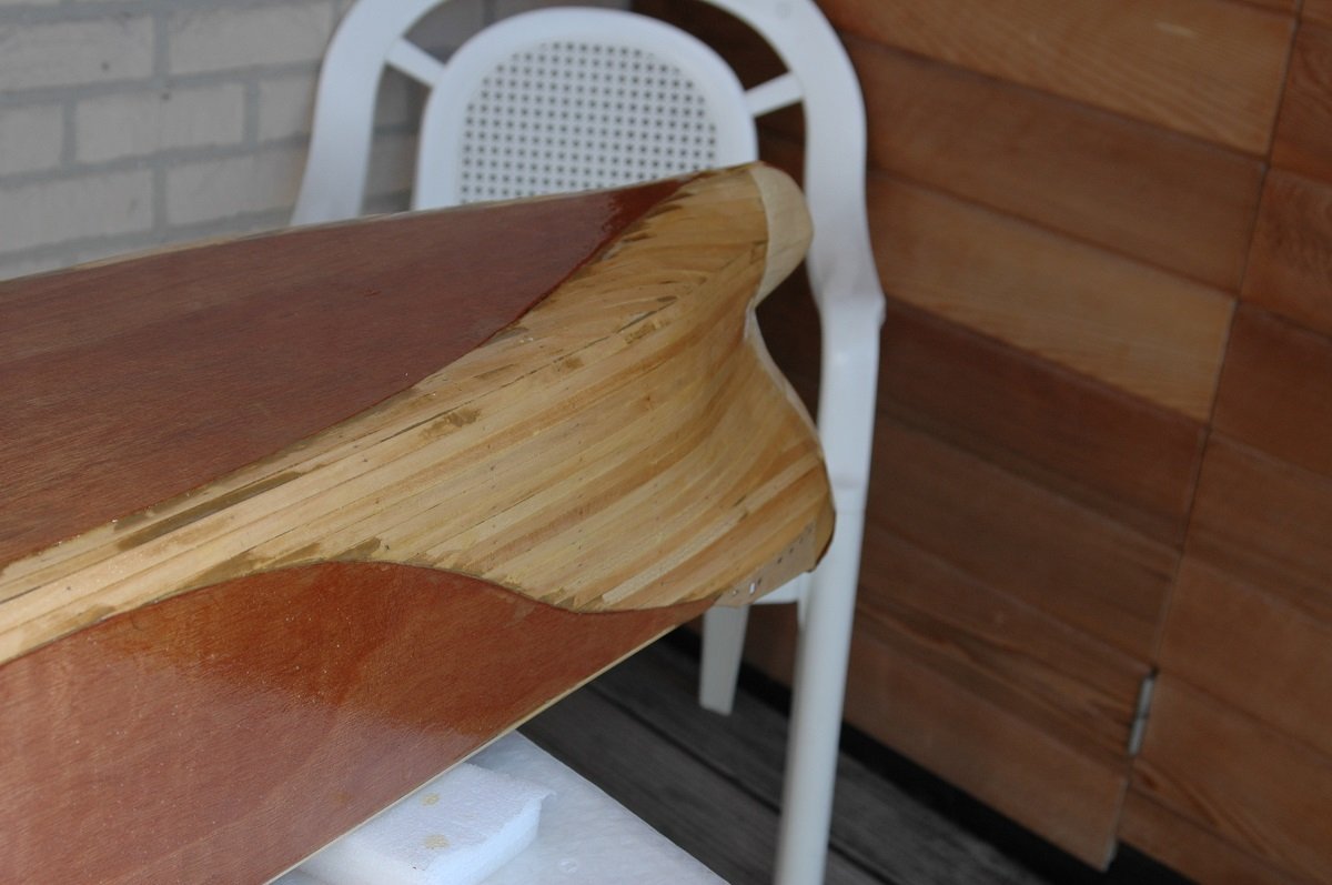
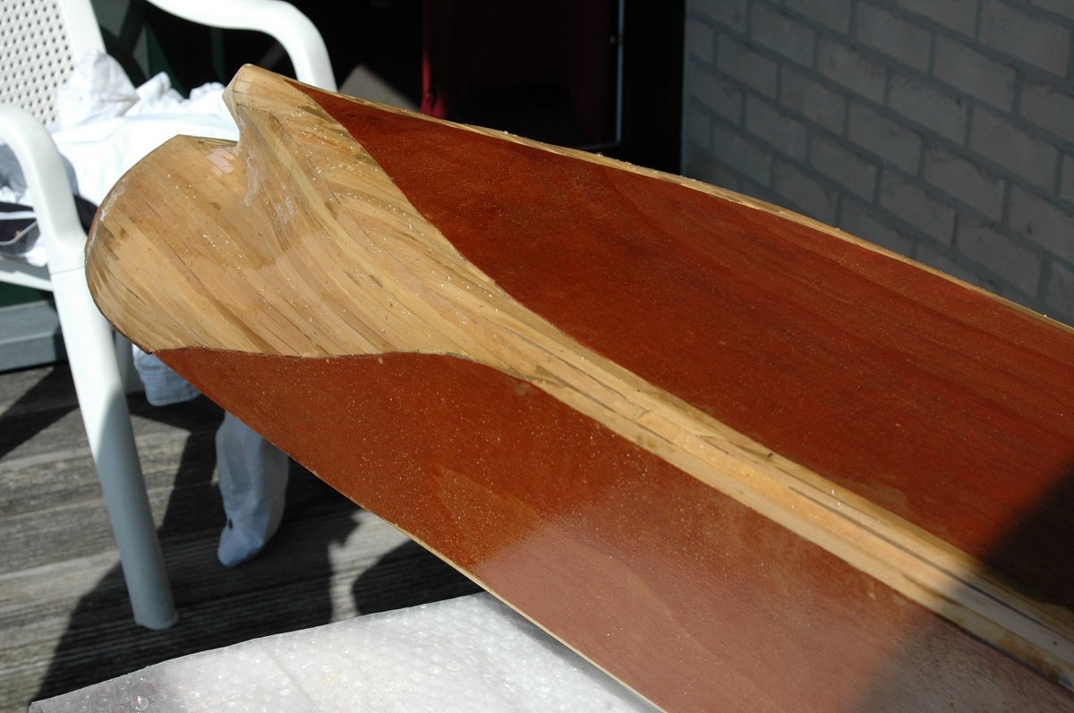
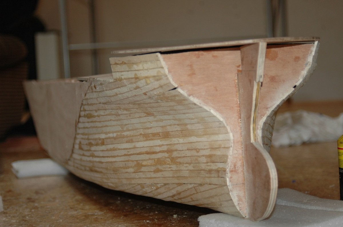
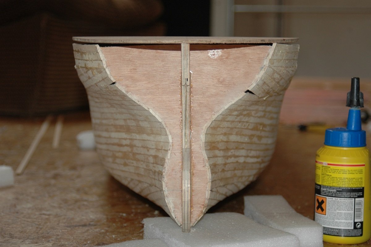
THe pictures aren't really ordered well on my pc, so here are a couple more planking pics of the stern. You can also see an inserted brass pieces to make a sharp transition above the propellor area. And an inside picture, showing the large volume inside the vessel. Back to where I left off last time. After the G4 came the fibreglass job. Again, never did anything close to that before and it turned out a small disaster. First of all, I did this on a rather hot day, reducing the curing time of the polyester resin even further. Secondly, it appears the G4 was still curing/drying, although I was already quite long past its normal drying time. I believe this had to do with the diluted G4 inside the wood. The result of the first mistake was that the polyester cured extremely fast, resulting in piece of fibercloth still sticking out without time to put it down in place. Also the mixture may have been slightly wrong as there is very little room for error with a mixing ratio of 97% A qnd 3% B... Probably too much hardener. The second mistake resulted in bubbles below the polyester shell. All in all due to the fast curing, this didn't really deform the polyester. The bow came out quite nice. As I mentioned, most things can be fixed, but making a good job from the start will save a lot of time later on.... In this case I started sanding away the fibercloth that was sticking out and resorted to a full cover of car body filler (also polyester based), followed by a LOT of sanding. And this angle was chosen to verify if I captured that strange bow shape properly. This already gave me some courage to proceed (something I was slowly losing after the polyester set-back.
-
There was a time when I created part of the gifts themselves, in addition to bought presents, but lack of time prevented that ever since. I'd still put something together when asked to, of course. Nice coffee shop. Revenge is coming along nicely as well, when the red part is planked and not red anymore, it will make quite a difference in appearance!
-
Great job so far. You sure are productive. I do get the feeling you're running away from masting and rigging 😏
- 21 replies
-
- 1
-
-
- Amati
- Victory Models
- (and 1 more)
-
Although I'm following you, I didn't see this one pop up. Happy to see another bottle-project started. Already curious how you'll tackle that bottle-waterfall connection!
- 174 replies
-
- 4
-

-
-
- Waa Kaulua
- bottle
- (and 1 more)
-
That's one very fantastic steel job! And at such a small scale! 👍
-
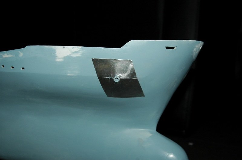
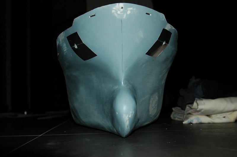
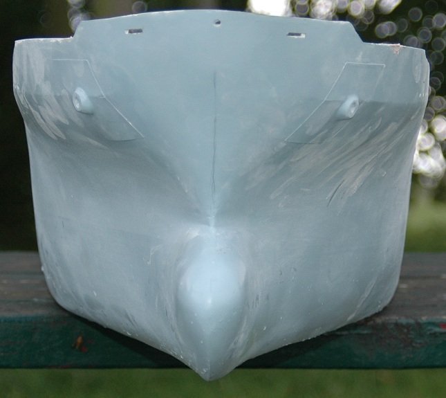
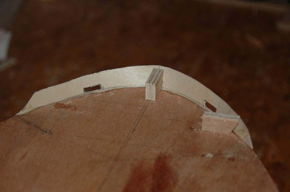
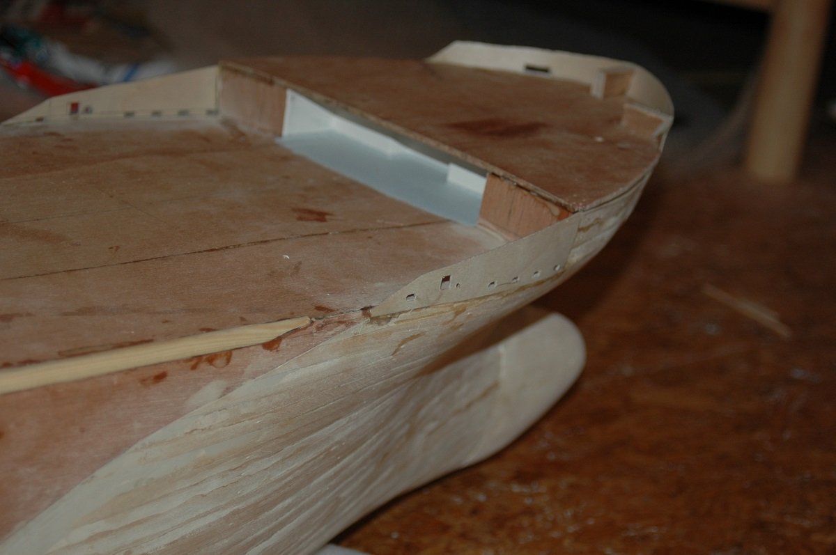
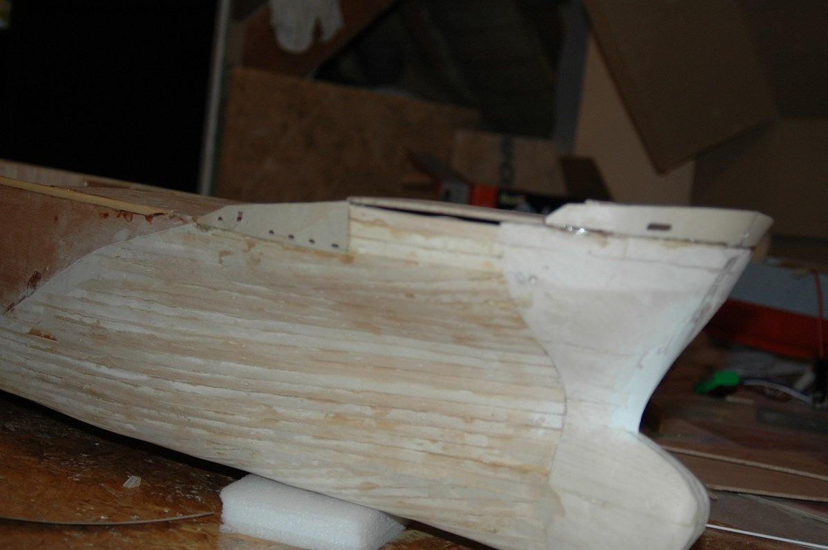
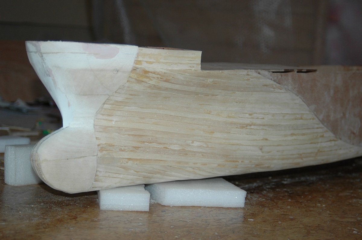
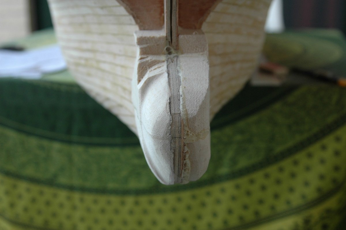
Thanks for all the likes and comments. On to finishing the hull before polyester application. First came the bulwark. Since the deck wouldn't remain pure wood, I decided to glue temporary blocks with the correct angle in place. I then shaped a bulwark from paper around that bow and transferred it to wood. I believe I used 3mm birch ply for this. Also the transitions from the forecastle deck to the main deck were made from that wood. You can also see the finish of the stem, using 2-part epoxy filler around the brass plate to reach a more or less sharp edge just above the bulbous bow. I used a very fine weave of fibre cloth with polyester resin. Since Polyester isn't really 100% water proof, the wood could start rotting underneath. I therefore treated it with a product called G4, which essentially turns the wood into plastic. First coats were thinned G4 to get it deeper into the wood, last coat was pure G4. Here is the G4 treatment. When drying it gave a satin gloss to the wood, but the colour of the wood turned back to "normal", eventually it was hardly visible that it had been treated. You can see small bubbles forming due to the G4 getting into the wood.
-
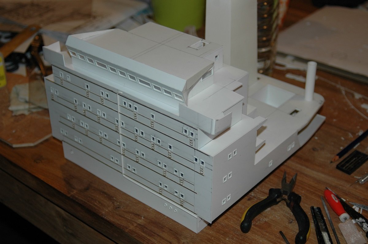
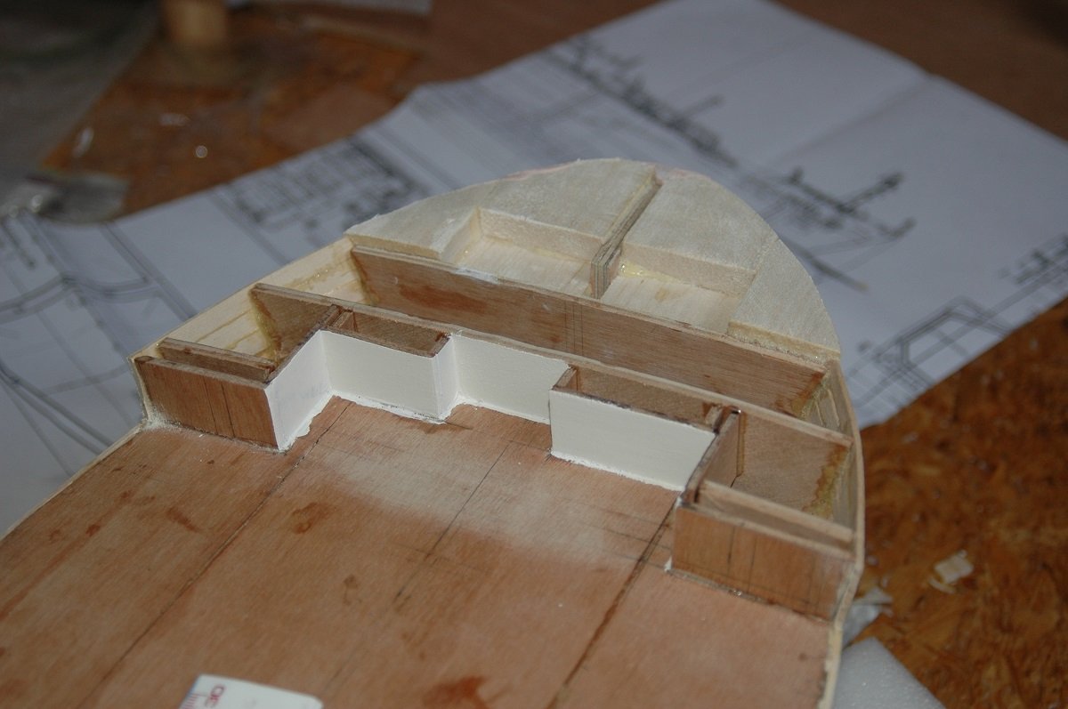
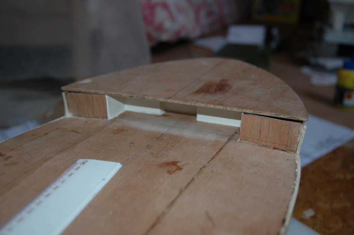
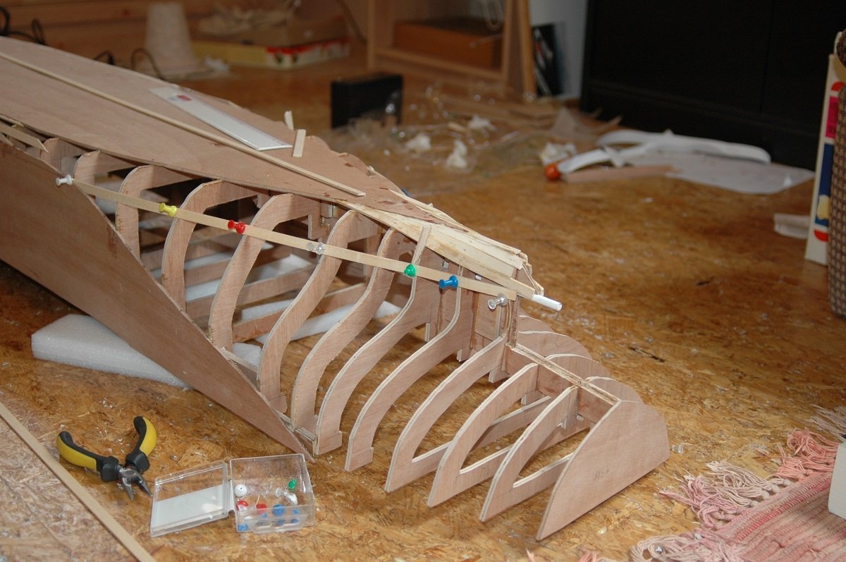
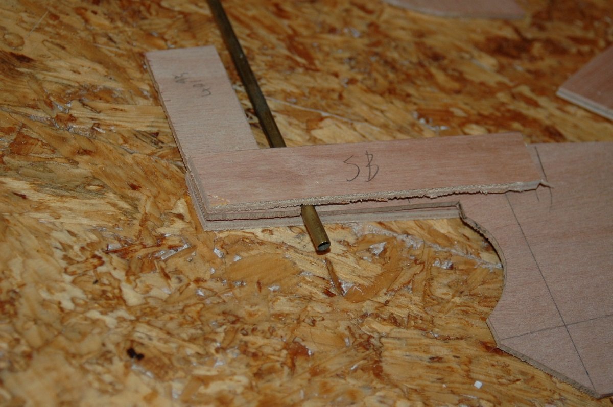
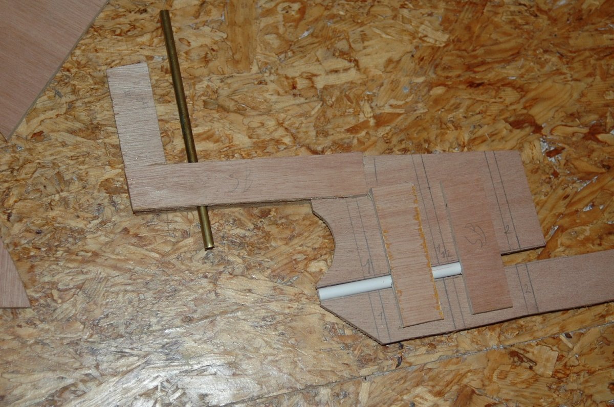
Here things got a bit fuzzy. Seems I finished that aft planking first. I believe I then put balsa blocks on the bow and near the prop shaft and then finished the part underneath the forecastle, since I wouldn't be able to reach it when the forecastle deck was in place. As mentioned before, I had started some major block construction in parallel (while the glue was drying on the planking I suppose). The front of the superstructure is just there for strength. Cutting all the windows from a 2mm thick piece of styrene is pretty hard, so I decided to make a false cover first, to maintain strength and then put a 1mm detailed cover in front. It's quite a piece, but it also had to be removable as it would give access to the motor and speed controller, so it had to be sturdy. Everything on those vessels is concentrated in 1 superstructure (apart from the cargo handling gear), so it also carries the funnel as well as the lifeboats and davits.
-
Only ones left are in the capital of our village . Come to think of it, with 2 ship modellers in 1 village, that will make the village the "ship modelling capital of Belgium" 🤣
-
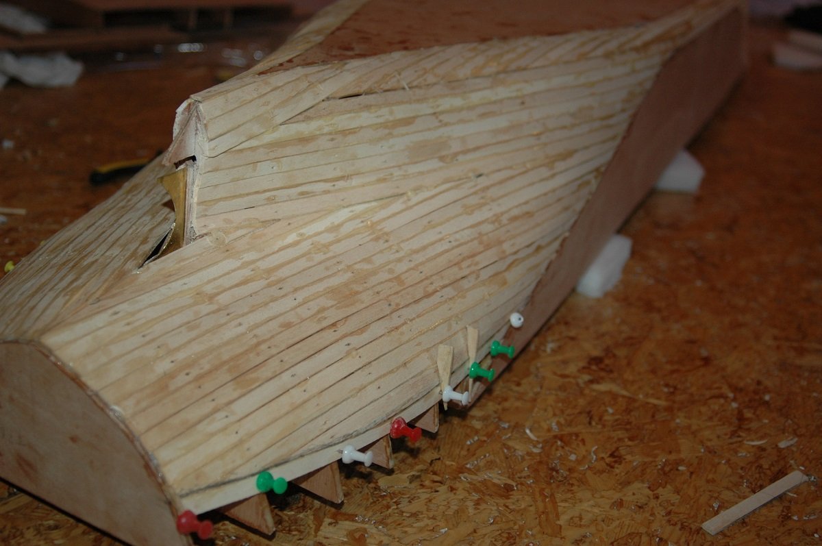
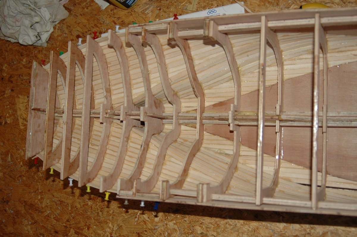
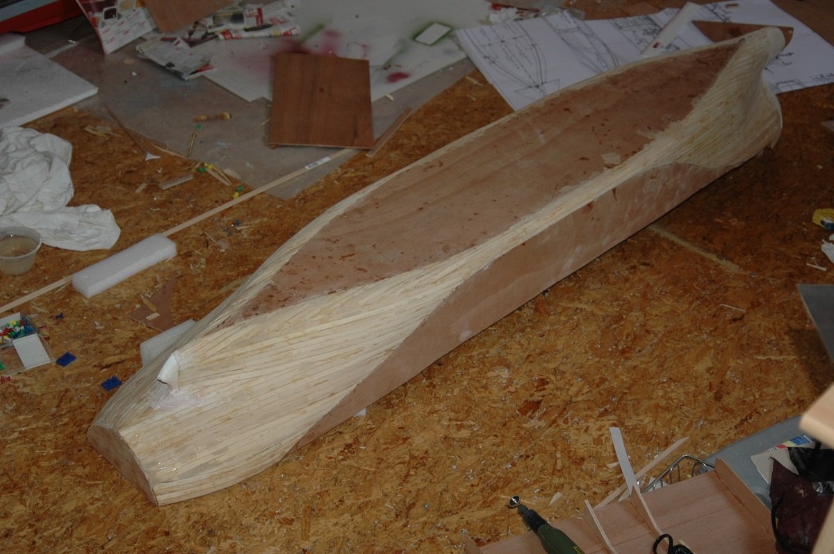
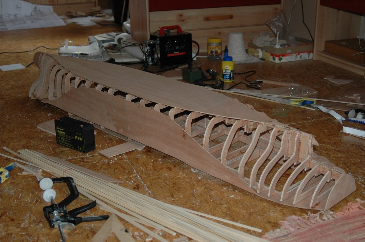
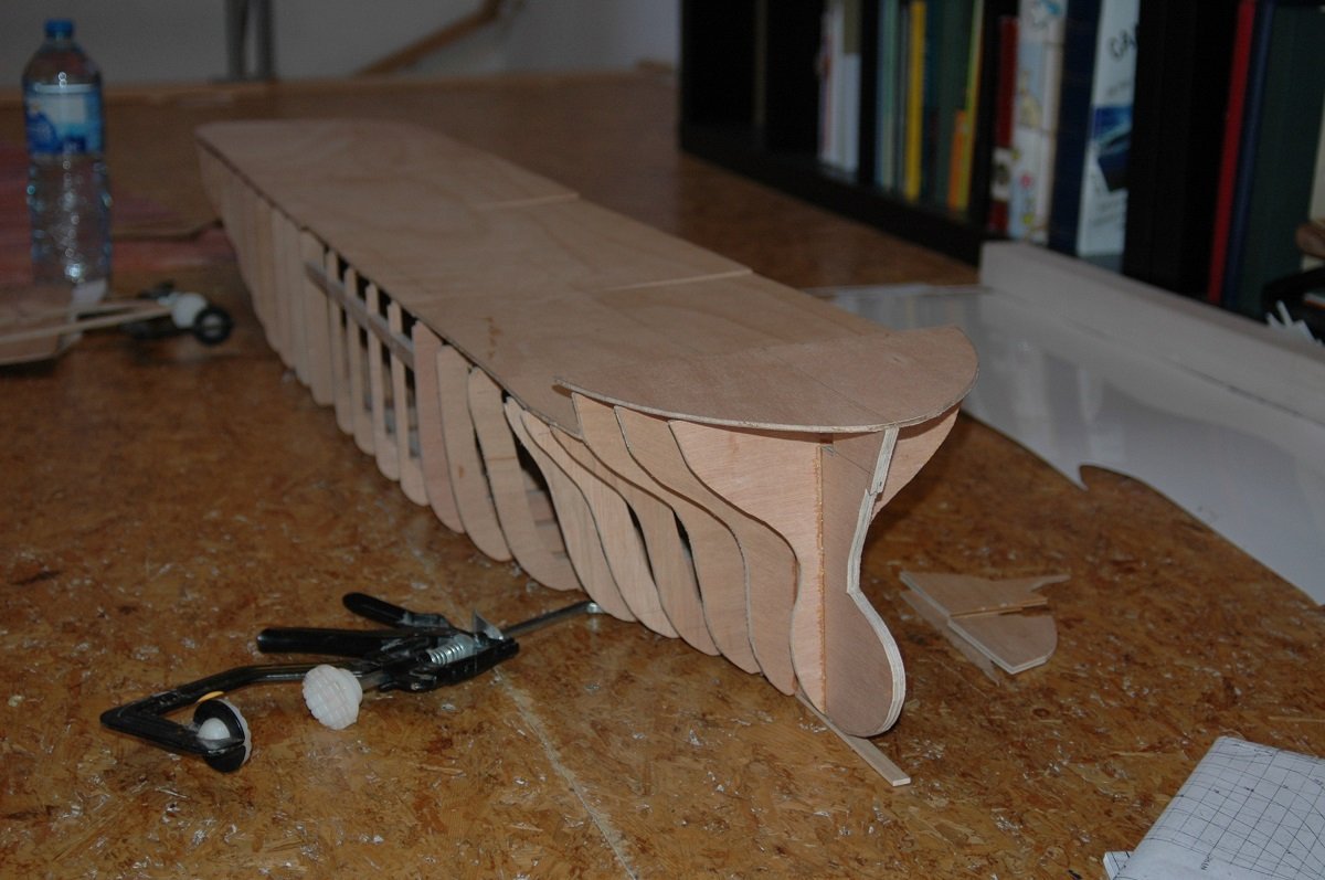
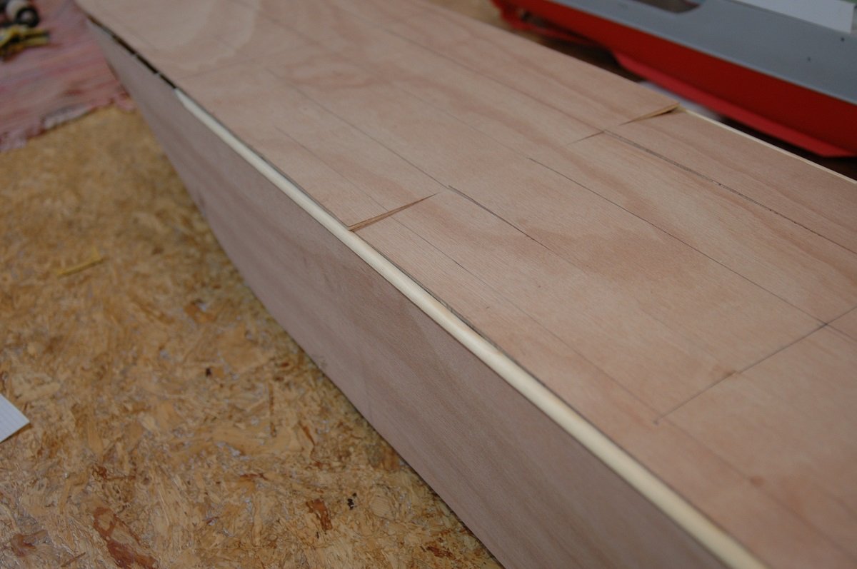
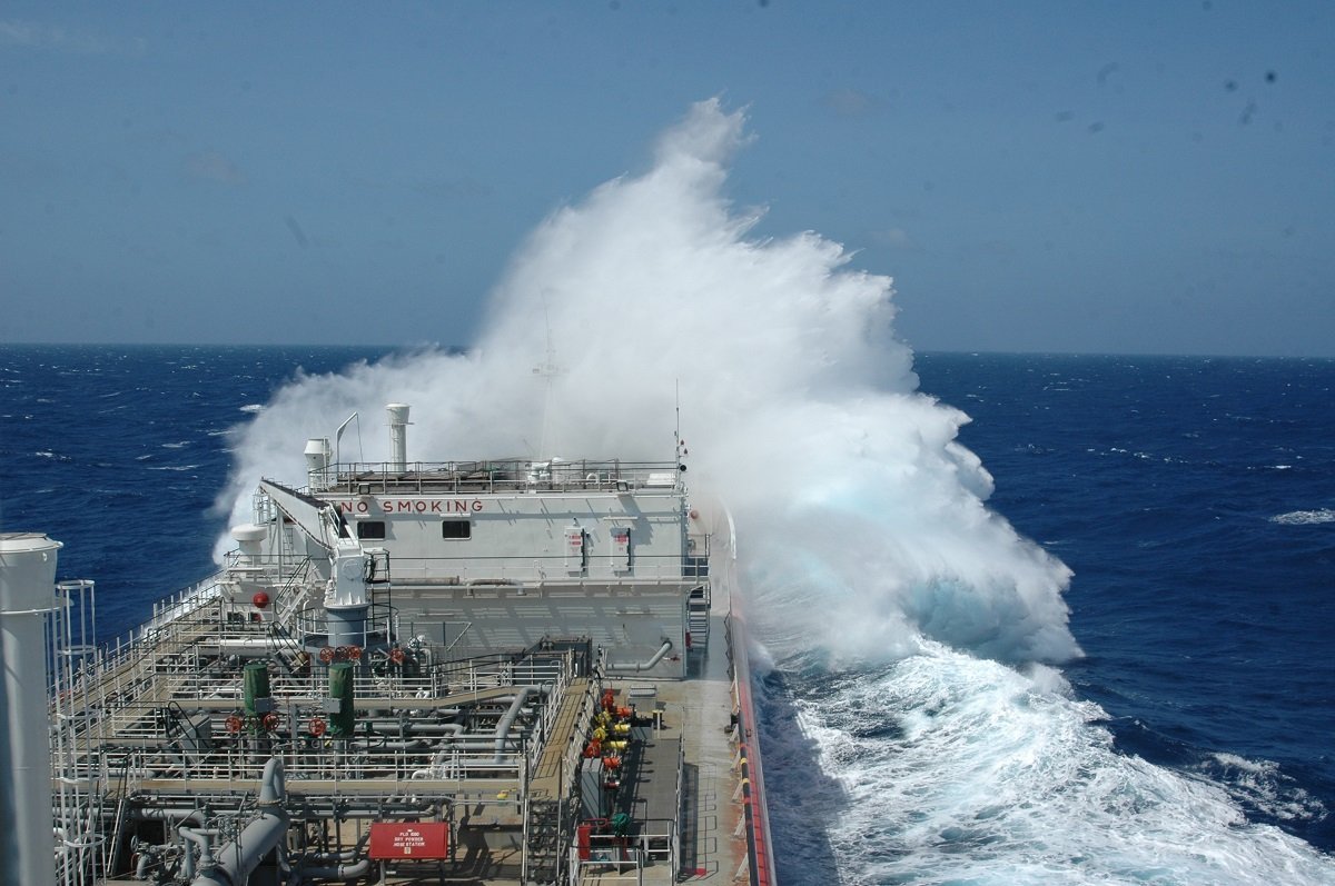
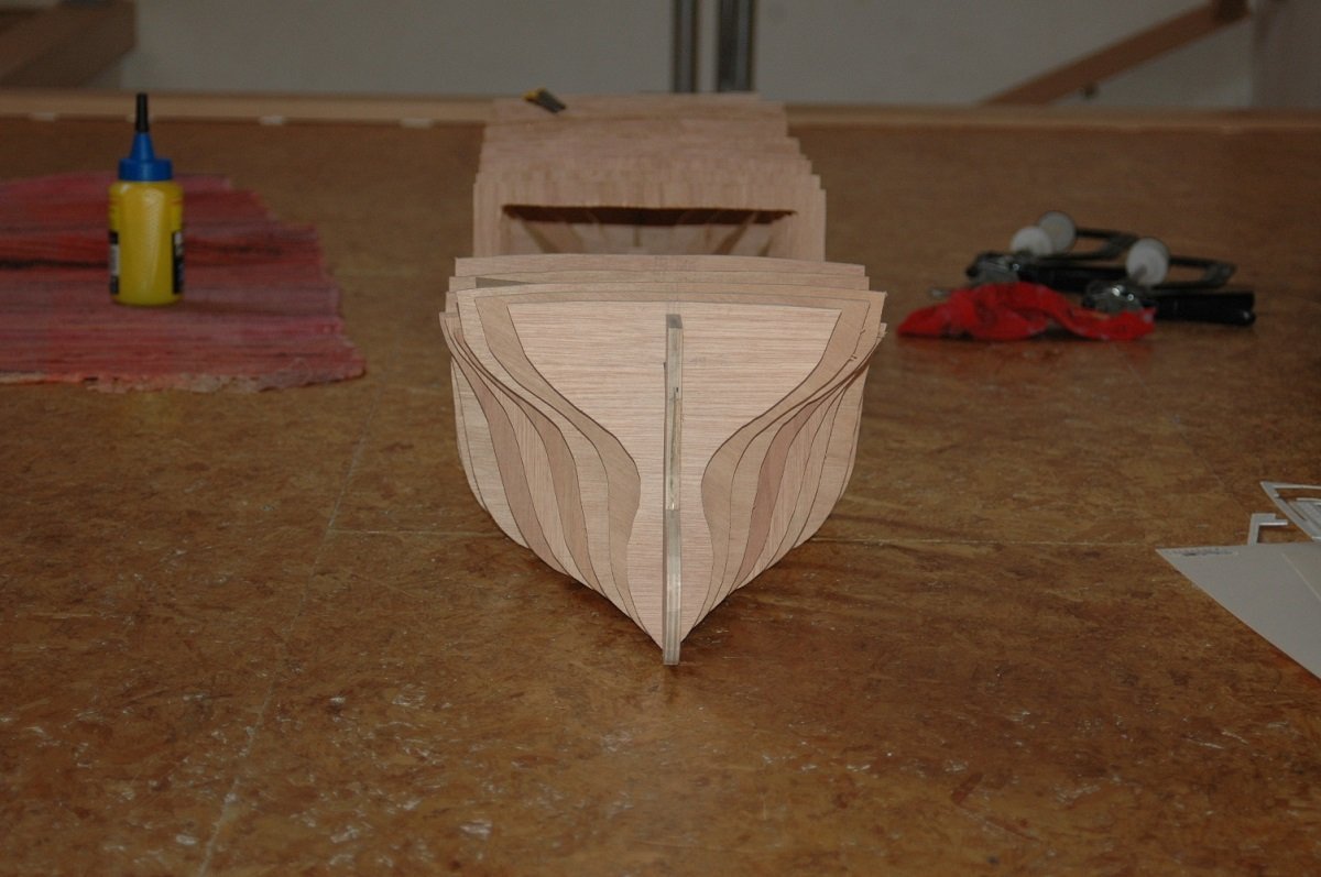
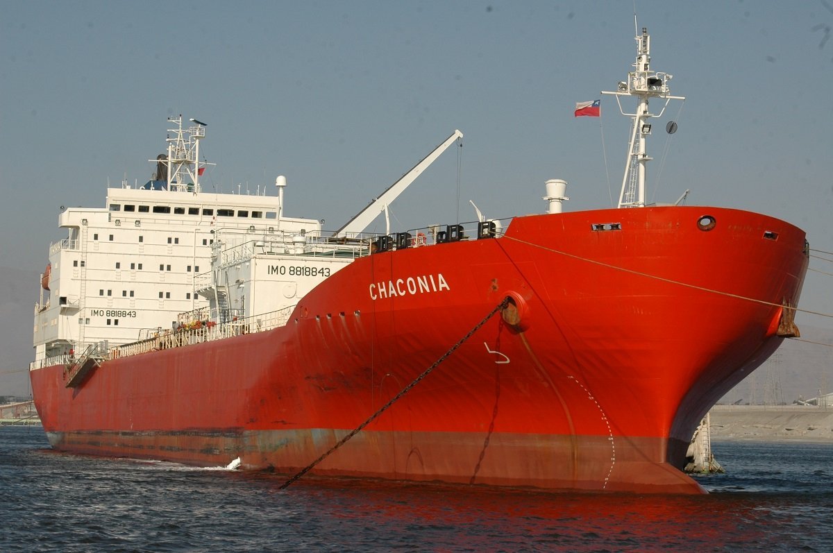
Indeed, slamming, but in an extreme way. All ships can slam from time to time, depending on direction and period of the swell, but in this case it was quite extreme. I also forgot to mention one sister. The Cheshire was built for a different company (Bibby Lines from UK, if I remember correctly), as far as I know she was from the Courcheville/Chaconia variant of 165m length. Eventhough they were of the same variant, Courcheville still different from Chaconia in a considerable way. Courcheville had 2 deck tanks (1 small for Ammonia, 1 large for Propane/Butane), while Chaconia only had the small deck tank on portside of the deck. On the original vessels, the deck tanks were also mounted forward, while on Courcheville and Chaconia they were both mounted aft. Chaconia did receive an extra mooring winch instead of that large deck tank. Deck tanks are used to change cargo. They are not really part of the cargo carrying capacity. If you transport Propane and your next cargo will be Ammonia, then the deck tank is used to fill your tank with ammonia gas and later on cool it down with liquid ammonia from the deck tank, in order to get the tanks ready for the next loading operation. Since ammonia expands a lot more than Propane/Butane and needs to be cooled down less than Propane (boiling point of Ammonia is around -33°C, while the one for Propane is around -42°C), the deck tank for Ammonia is smaller. This is only an option chosen during construction. If the ship is not supposed to change much cargoes, 1 or 2 deck tanks can be left out of the design. When all old cargo is removed and the tanks are gas free, it is also possible to fill with gas (gas-up) and cool down alongside of a terminal. This costs time and money, but if required, it can be done. There was also a chiller unit, a special device that allowed to load warm cargo, cool it down with the chiller before it entered the tank. Although there was space for this unit, Chaconia didn't have it installed, Courcheville did. Not sure on the others. Time for the planking. I apparently started with the bow. The wood I chose was lime, which worked well. I did wet the wood and shape it before applying it. I used an epoxy construction glue that actually bubbles and filled gaps when drying. Glued the planks to the frames as well as to each other. Getting them smoothly connected to the flat sides was something of a challenge, not sure if I'd go for complete planking on a new build (that would be a lot more costly though). I soon figured out the planking went up towards that bow, quite steeply. Oh, and I forgot to mention, I completely left out shaping the frame edges to the hull shape, figured the glue would compensate for that🤪 So at some point I decided to make a cut, get a straight plank running aft to forward in place and continue straight. At that point, being young, not held back by any knowledge or experience in the matter, I always assumed I would "fix things later", something I don't do anymore, nor would I advice it to anyone. Although many things can be fixed, it takes an excessive amount of time and effort to do so. On this bow shot you can see a brass plate in place at the stem, in order to be able to make a sharp edge. Something I had foreseen to become a problem when using Polyester and car body filler (= "the solution"). The planking did end up more or less symmetrical. Then came the stern section, with even worse curves to negotiate.
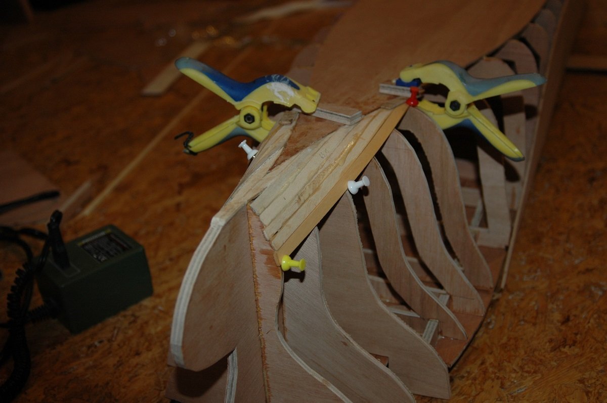
-
Welcome aboard. Almost impossible to believe, a large international community of people in a rather small hobby (definately in Belgium) and you live in the same village as me....
-
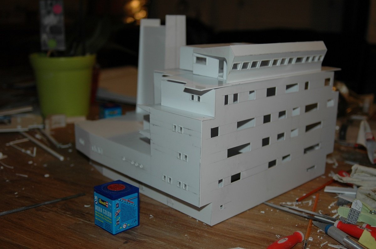
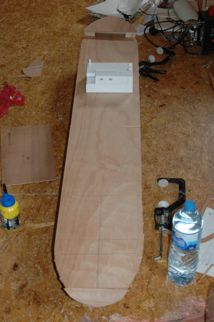
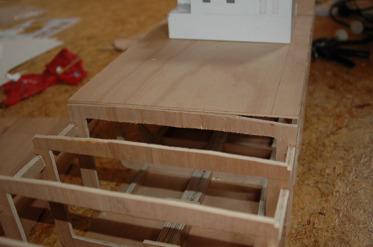
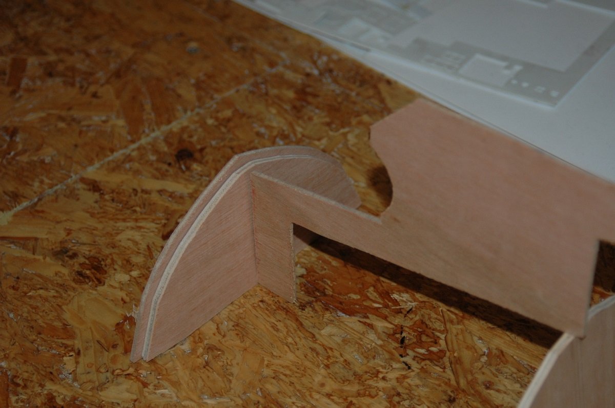
@Ian_Grant, 30kg would be full load. I've already sailed with her in the past and I only went to 20-22kg, basically assembling it in the water. I just put the hull afloat, and then add ballast and battery. If I remember correctly the hull itself is around 12kg. I'll try to update daily until I am at the current situation (and then it will slow down considerably). Here is one pic with that cargo tank in place. I sure was ambitious back then. The cargo tank was a sort of educational piece that could also open to show the inside structure of the tank and the pumps etc. I did get further than what you see in this picture, but when it was clear I wouldn't have time for that, it got shelved and eventually scrapped. You can also see that the outside corners of the frames adjacent to the tank (and more aft) were cut. This was already with the idea that I'd insert a quarter rod of wood to resemble/model the rounded edges of the decks which are typical for tankers (this avoids excessive stress on the corner joint of the main deck and ship's sides). Next was fitting the decks. As you can see in the next pics, once I was more confident on that hull coming together, I started with the large block construction using styrene. The deckhouse, also called cargo compressor room is here in place. This room houses the three cargo compressors (1 for each cargo system + 1 spare that could be put on either of the 2 systems to give more capacity to that system). In below picture you can see how much camber the hull has. The camber allows green water to be evacuated quickly over the sides. This of course meant the main deck would be cut length wise to compensate for this angle on both sides. Here the main deck is already cut to pieces and the quarter rod on the edge is places in the frame corner cut-outs. The part below the cargo compressor room, what housed the cargo tank 2 model, would remain removable. This appeared to be a good choice later on, as it gives an easy access to the batteries and ballast. And what I forgot to mention about that bow shape... By leaving out the fuel tanks forward, the bow was very blunt. They wanted to maximize the cargo tank capacity, which meant the forward cargo tank was still quite considerable in volume and the bow was shaped to accomodate this rather big, blunt tank. The blunt bow shape did give a very "strange" behavior in certain sea conditions, resulting in the ship colliding with the swell on occasions. It felt like going from full ahead to a dead stop whenever you hit a wave. This (or at least it was thought back then), eventually led to some structural issues in the forward part of the vessels.
-
The product I use only mentions masses/weights, not volumes. Kind of normal considering chemistry is mass based. Volumes change with temperatures and pressures for a given mass. (although arguably less important for epoxy than with polyester with mixing ratios of 97%-3%) I use Epodex, which has two very different sizes of bottle (hardner and resin) and the mixing ratio is therefore also different from 50-50. It's practically made two mix the bottles completely, they don't really consider partial mixes. That said, it can be easily calculated. The only issue is that they don't give densities, so when you need a certain volume of epoxy mix, you need guess the densities and convert it. It did work so far, although I believe I used too little hardner in my first trial, resulting in too much hardner remaining in the end...
-
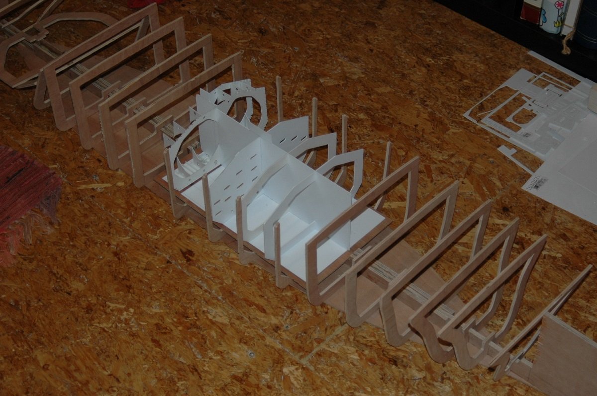
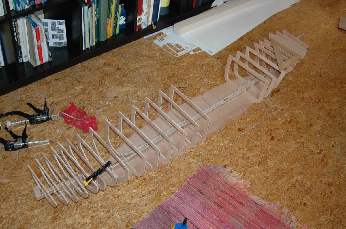
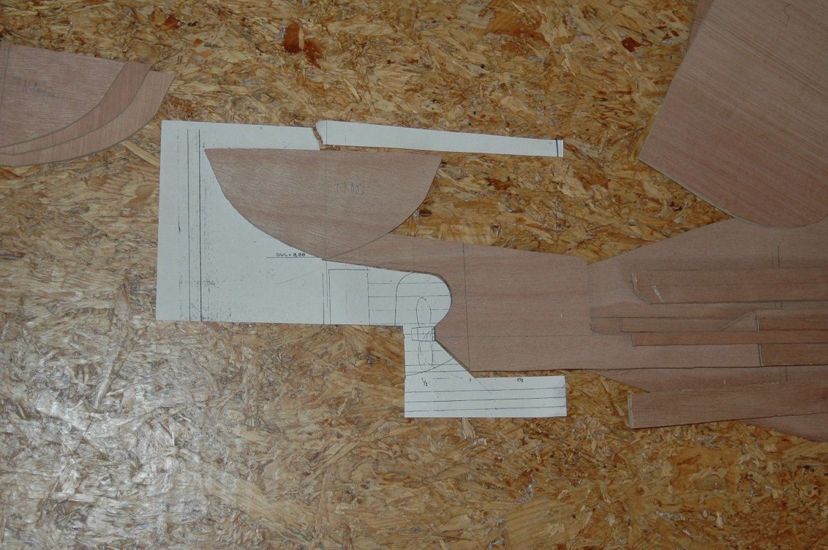
Thanks for all those likes and reactions. Some more progress. I'm still looking at how many and what kind of pictures I have from those days. A bit of history on the what and why: Chaconia was 1 of a series of LPG tankers built in the Belgian Boelwerf at Temse. The series started with the slightly smaller Tielrode (later renamed Oscar Gas I believe) and Gent (both 155m long), and was followed by the slightly longer Courcheville and Chaconia (both 165m long) and by the even larger Sombeke, where the main deck was level with the foreship. They were Midsize LPG tankers (as opposed to the standard 236m long Very Large Gas Carriers) built to transport different cargoes. Mostly they carried Butane and/or Propane and Ammonia, but they could also carry VCM (Vinyl Chloride Monomer) or Propylene (basically anything with a boiling point down to -48°C. They had 3 tanks, arranged in 2 seperate cargo systems. Each system consisted of 1 Vent Mast, 1 cargo compressor (= reliquefaction unit) and 1 or 2 tanks. The systems could also be connected to a single system and the middle tank could be connected to either of the 2 systems (basically creating 1 single tank system and a seperate 2-tank system). All this allowed flexibility in the amount of each cargo to be carried. Their rather odd bow shape was the result of the lack of a fuel tank forward. Normal merchant vessels have fuel tanks adjacent to the engine room, but also fuel tanks forward. These tanks are normally transferred to the tanks near the engine room once space allows (during the voyage). These tanks also allow to shape the bow in a hydrodynamic way when required. In this case they chose to omit those forward tanks. Reducing the need for a forward fuel transfer pump station and fuel piping on the forward deck. Next series of pics is the framing job. As you can see, there is a flat bottom, allowing for the use of flat wood plates. I used this plate as a sort of building board, but you can imagine it wasn't very straight. Big mistake, wouldn't do that again, but not a disaster after all. The frames on these pics were also still dry fitted and a bit wiggly, so they look more out of line then what they'd eventually be. Also it appears I used the wrong tool to cut those frames, I'd do a better job on that as well. Merchant ships also have flat sides nowadays, so I opted to use wood plates for the size as well. The parallel body is in most cases also drawn on the vessels drawings, this allows to see if mooring at certain terminals with certain fender arrangements (or ship to ship transfers at sea) are possible. The last shot has a ruler in it, you can see the size of the beast. The midship section was to have a real model of a cargo tank inside, that's why the frames and keel in that position are shaped differently. I did start that tank as well, but discarded it by now. It is however a good spot for the ballast and batteries now. In loaded condition the model should weigh around 30kg.
-
True that in this case it remained enclosed in a glass jar since I didn't pour it. The actual piece would have a much larger surface vs thickness ratio. The final piece is 14cm x 14cm and somewhere between 1.7 and 1.9cm thick. That would also allow bubbles to escape faster. On the other side, too much hardener does create a faster chain reation, creating more heat in a shorter time. I've ordered new epoxy and this time I will weigh it carefully. Should arrive somewhere next week. She's on hold for the time being, since I won't put additional time in this until I'm sure the epoxy works fine. (worst case, I'll saw the whole bottom off and it becomes a waterline diorama 😁) Thanks Nils, not that accurate I guess, but a very different way of building than large scale. In this tiny scale you have to very carefully consider what you will and won't represent.
-
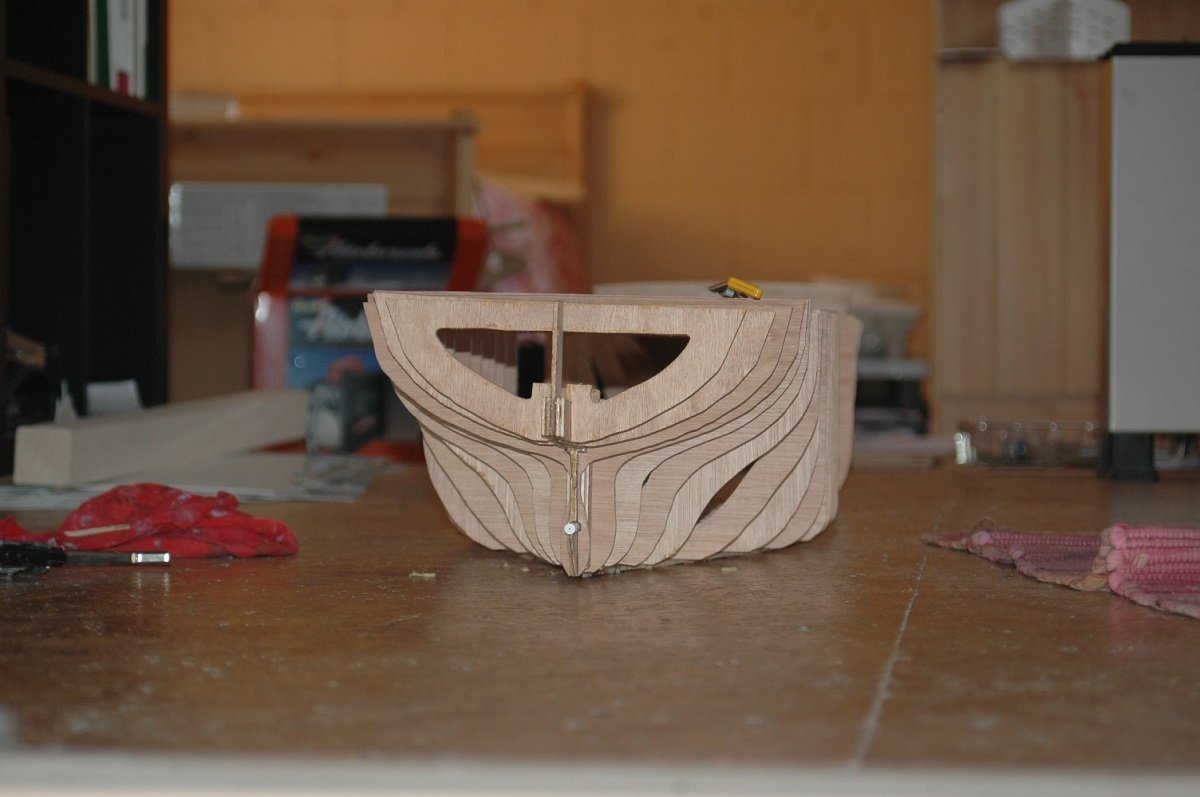
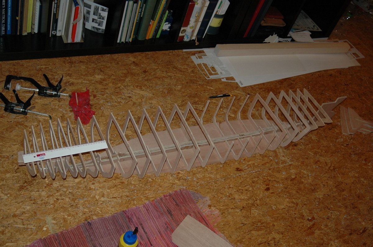
Well a very old project of mine started back in 2010. It's been around ever since, working on it on and off until now. It's been bothering me ever since, she's the reason why I don't like to have a shelf of doom with long lasting projects. With every new small scale project I start, she's standing behind me, nagging for attention. As of late I've been busy planning to finally finish her and since the Spartacus project is on hold for the time being, I've slowly restarted construction on Chaconia. At first I built in a continuous period, however the pace slowed down during the detailing phase and eventually I've abandoned it. At first it would be temporary, just to take on a smaller project and finally get something finished, but as you can imagine, then came another "quick" project and another... Sometimes I did put her in the water and did some small jobs, but it never became my main project again. Now I'm intending to promote her again to the main project. So what is she? Chaconia is an LPG tanker, carrying Butane, Propane (or both) or Ammonia. Back in the days, she was mainly used to transport Ammonia from Trinidad (and other places) to the US (Gulf of Mexico area) for fertilizer production. She also brought Ammonia to Chile for production of explosives for the mining industry. She's not the cutest of ships, but back then it sounded like a good idea. In the end, so many years later, I must say that my period onboard that ship was probably, travelling wise, the most interesting voyage I ever did, covering a large part of South and Central America, including Maghellan Strait and Panama Canal passages. Since I didn't have a lot of resources back then, she was built in sub-optimal conditions and I also didn't have any expertise for such a project, having just started scratch-building in small scale ships. I shouldn't have done a project like that as a first large scale scratch build... In any case, she's there now, so I'll need to finish her. I'll bring you up to speed in probably quite a few posts with pictures. Basic construction was a wooden frame and hull, covered with glass fibre. From the start the R/C idea was incorporated and that complicated things. I had seen a lot of R/C projects online, but they were always twin screw warships. Having a straight, single-piece, keel, which wouldn't work for my project. So I had to get a solution. It's also my first- and only- planking job till now. The rudder post in position. Rudder post and propellor shaft spaces created.
-
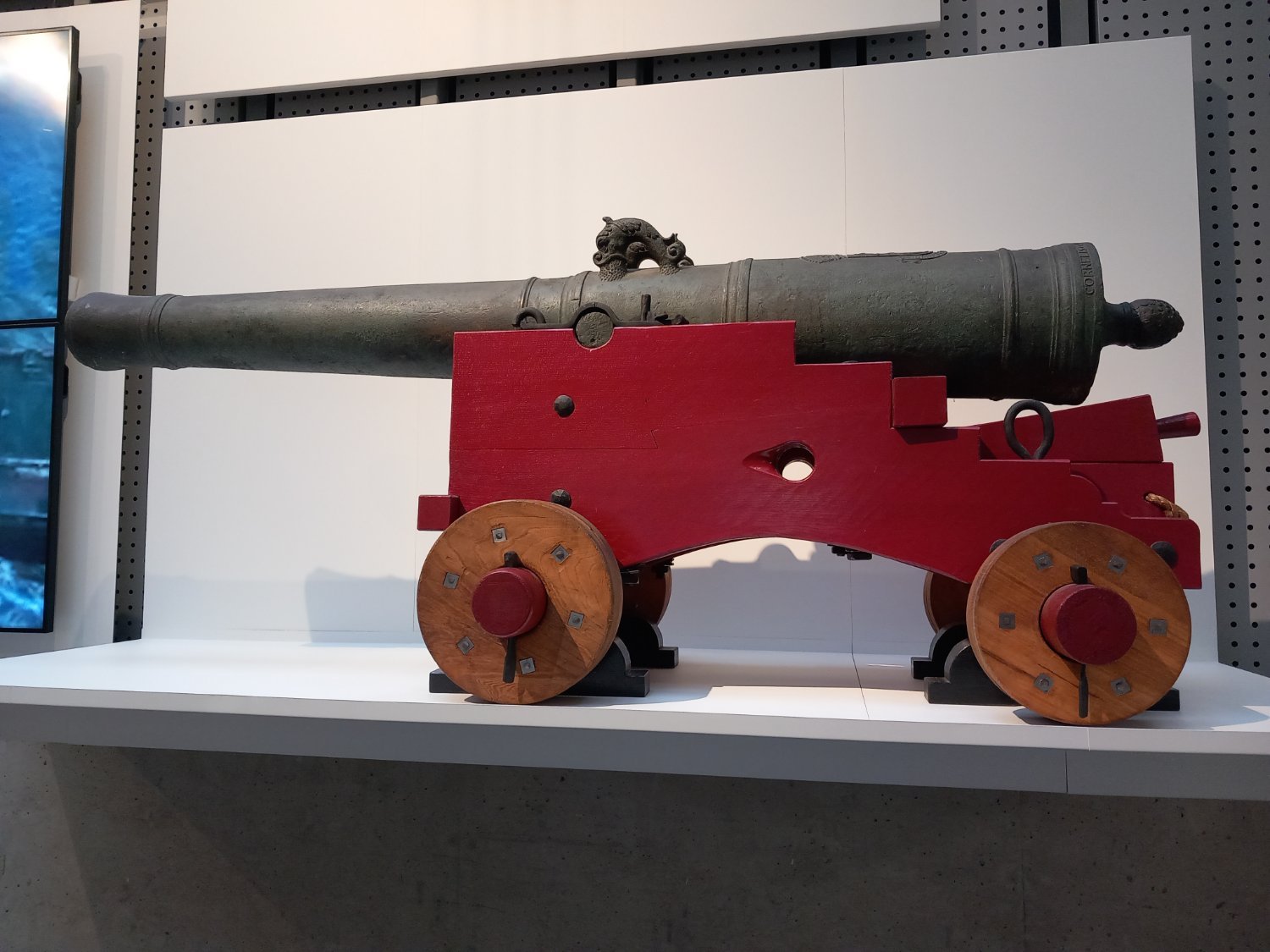
Noticed someone making an angled surface in his carriages rather than a regular top/bottom straight edge. I can't remember in which topic this was, but I remember someone asking whether there was any evidence. Since I came across this one in Rotterdam recently, decided to put it here for future reference. Any additional info on it would be welcome as it was placed at the entrance of the maritime museum, as a sort of attraction to lure public rather than inside the museum itself. No info was near the gun. I assume, considering there are no eye-bolt etc. that this might be an older type of gun/carriage? As you can see it does have that angled edge between top and bottom piece, much like I remember seeing someone doing here on his model guns.

-
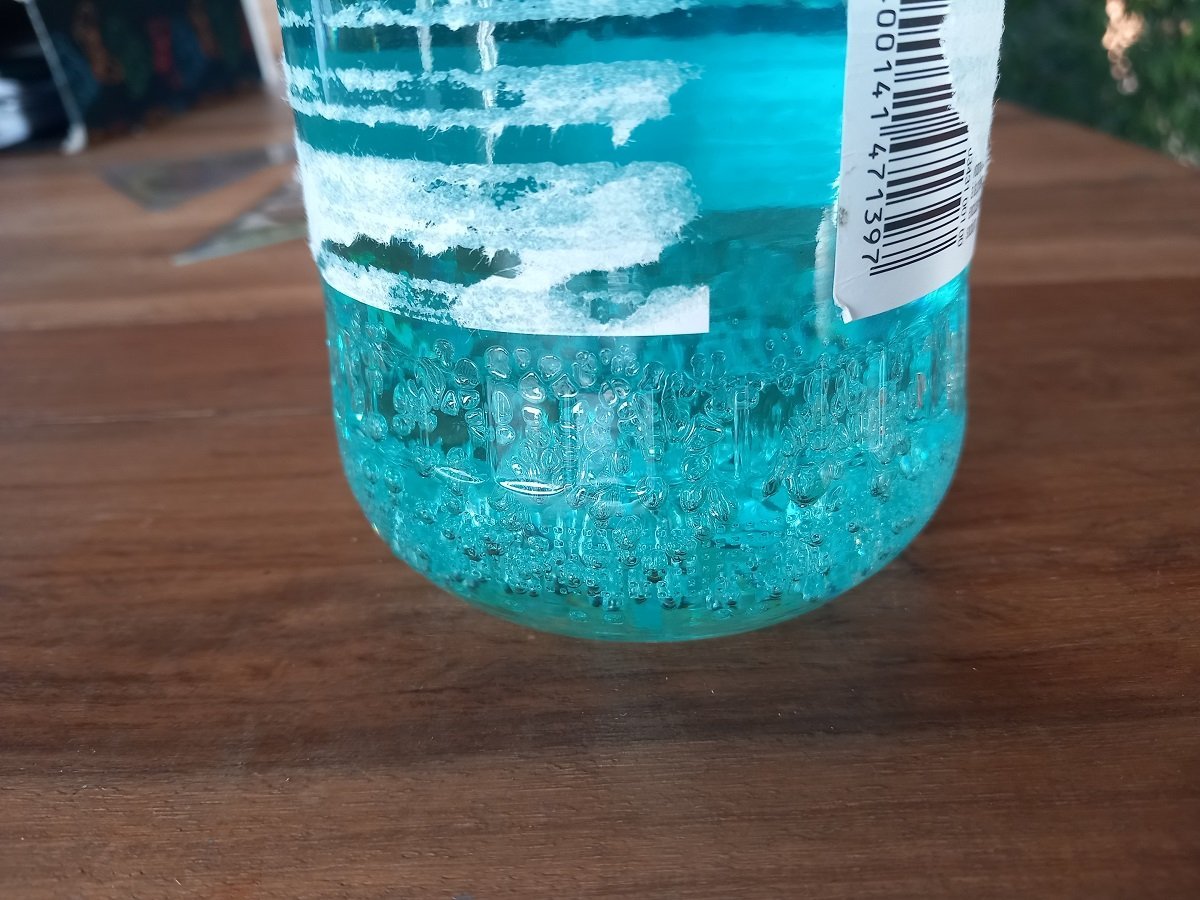
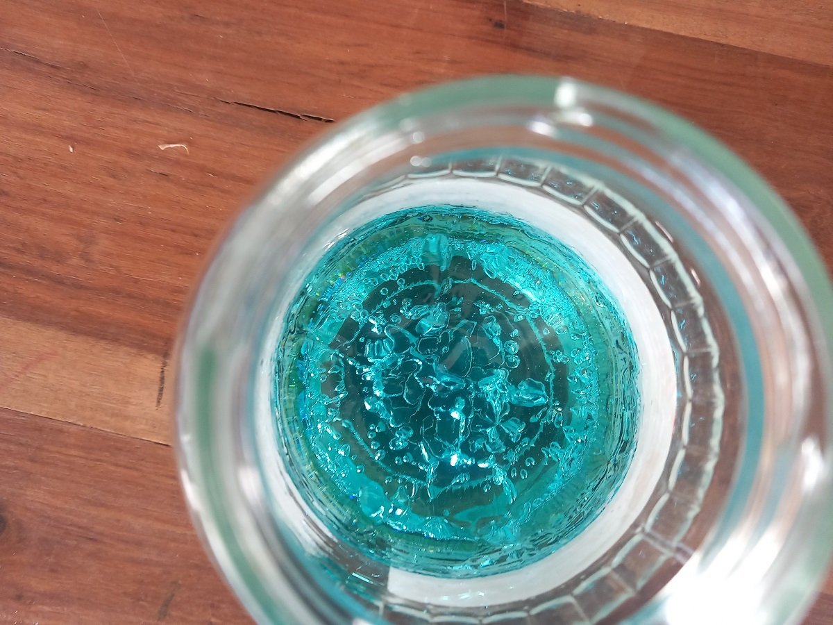
Because a picture says more than a 1000 words... The bubbles were not visible, even after 1 hour, only after that, it started to feel warm and the flakes seemed to dissolve, creating strange "streams" from the bottom to the top. Back then it even still looked smooth, but with those flows going up, the surface had lines in them and isn't even flat anymore. In any case, luckily I didn't push through.
-
Had a narrow escape today. I was all geared up to get that pouring job done this morning, but when I checked the contents of my remaining resin, I had my doubts about the remaining quantity. I required around 0.4L of epoxy for this diorama, and the resin bottle was only around 50% remaining, I forgot the wastage from the Sea Installer tests and the actual project. Together with the hardener I might actually have enough... In any case, it was open for a while and I had to use it sometime. During emptying the resin bottle, I did notice some white particles inside the liquid and when I was mixing with the hardener, those flakes remained in the mixture. During mixing however, the mixture remained opaque rather than turning back to clear, considering the low amount, I decided not to do the pour at all. When left to harden, the flakes slowly went down, but bubbles formed. The mixture also turned very hot, I was kind of lucky I mixed it in a glass jar rather than a plastic one. It also started to smoke (slightly), so I put the thing outside, where it was also colder than inside. Eventually it hardened, but there were certain "lines" in the mixture and large bubbles (what looked like a boiling reaction) formed from the bottom up. I 'm assuming there are 2 reasons for this: a) the stuff was too old / too long in opened condition before use or stored in a wrong temperature and b) the mix ratio was probably not good. I didn't weight this mixture as I had done several mixtures which worked ok, and I needed all of the remaining liquid. I suppose there was too much hardener left, creating a very rapid curing, releasing a lot of heat in a short period of time. I guess I was lucky, since I assume it would have melted the model if I had poured it in. Would have also been stupid if the amount was just enough to touch the bottom of the ship and not reach the waterline... She's shelved for the time being, need to order some stuff for several builds (finally need to finish that Sea Installer build as well). I'll see when I get to another attempt.
-
Great job you are doing there. There is also a material called Elforyn, a synthetic substitute for Elephant or Mammoth Ivory / tusk. Not sure how to glue it, but I'm pretty sure that company will help you with that. If it needs gluing of course. I suppose you can buy it in whatever size you need it, considering it's synthetic. https://www.elforyn.de/en/
-
Stupid question from somebody who never did this: did you pre-drill the holes for your screw pins against splitting of the frames or was this not required? Great planking job so far!