JacquesCousteau
-
Posts
1,383 -
Joined
-
Last visited
Content Type
Profiles
Forums
Gallery
Events
Everything posted by JacquesCousteau
-
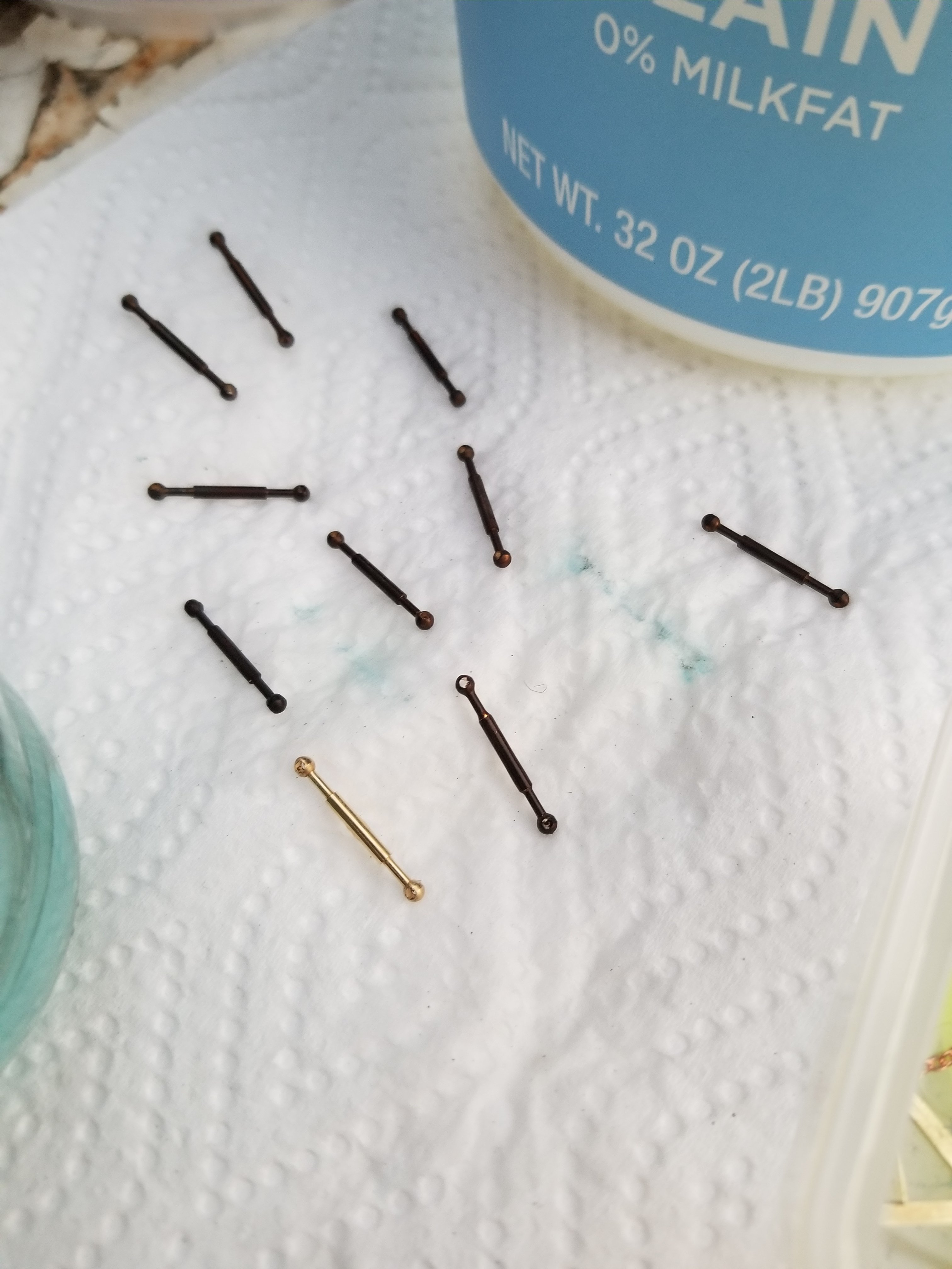
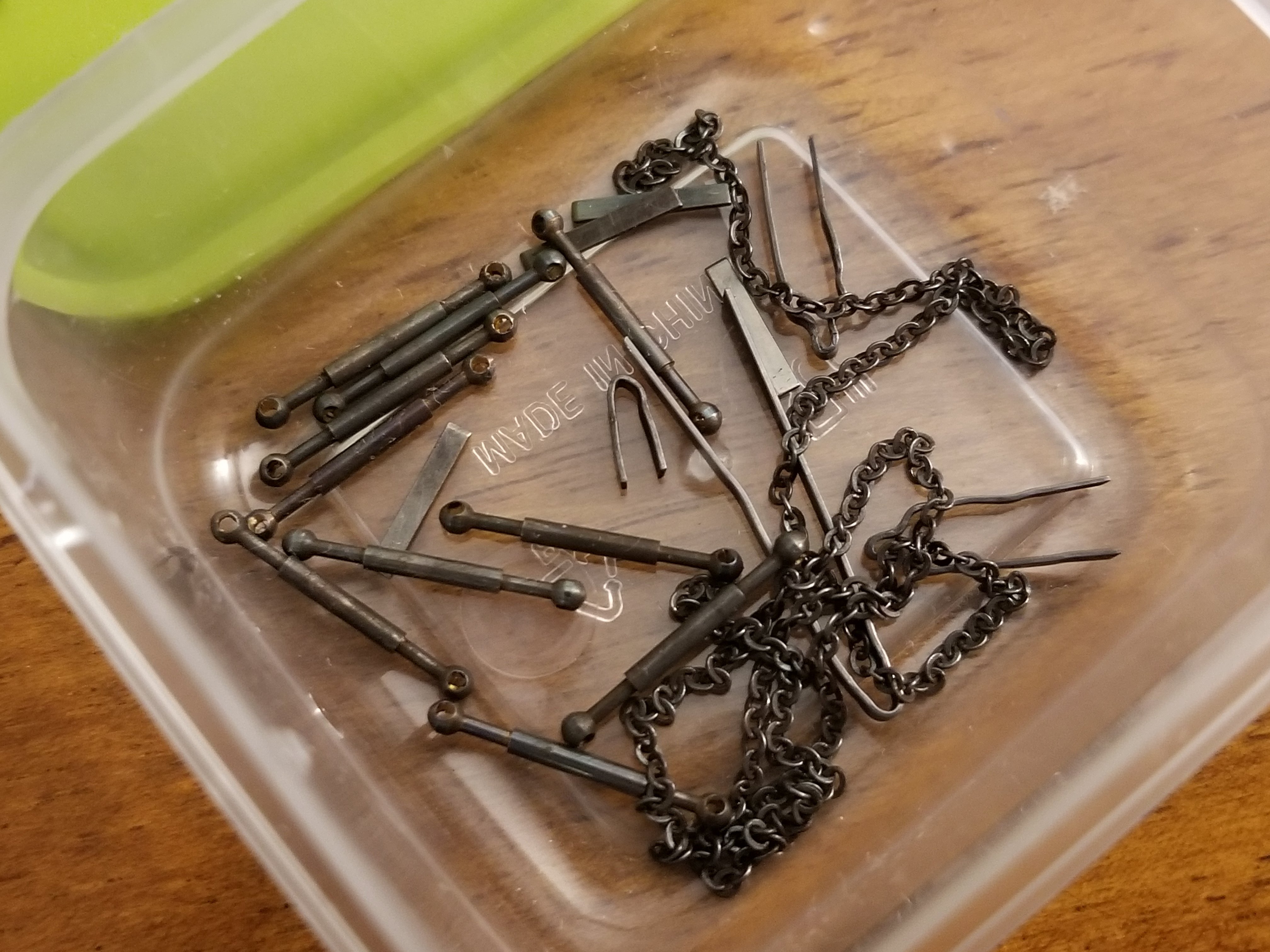
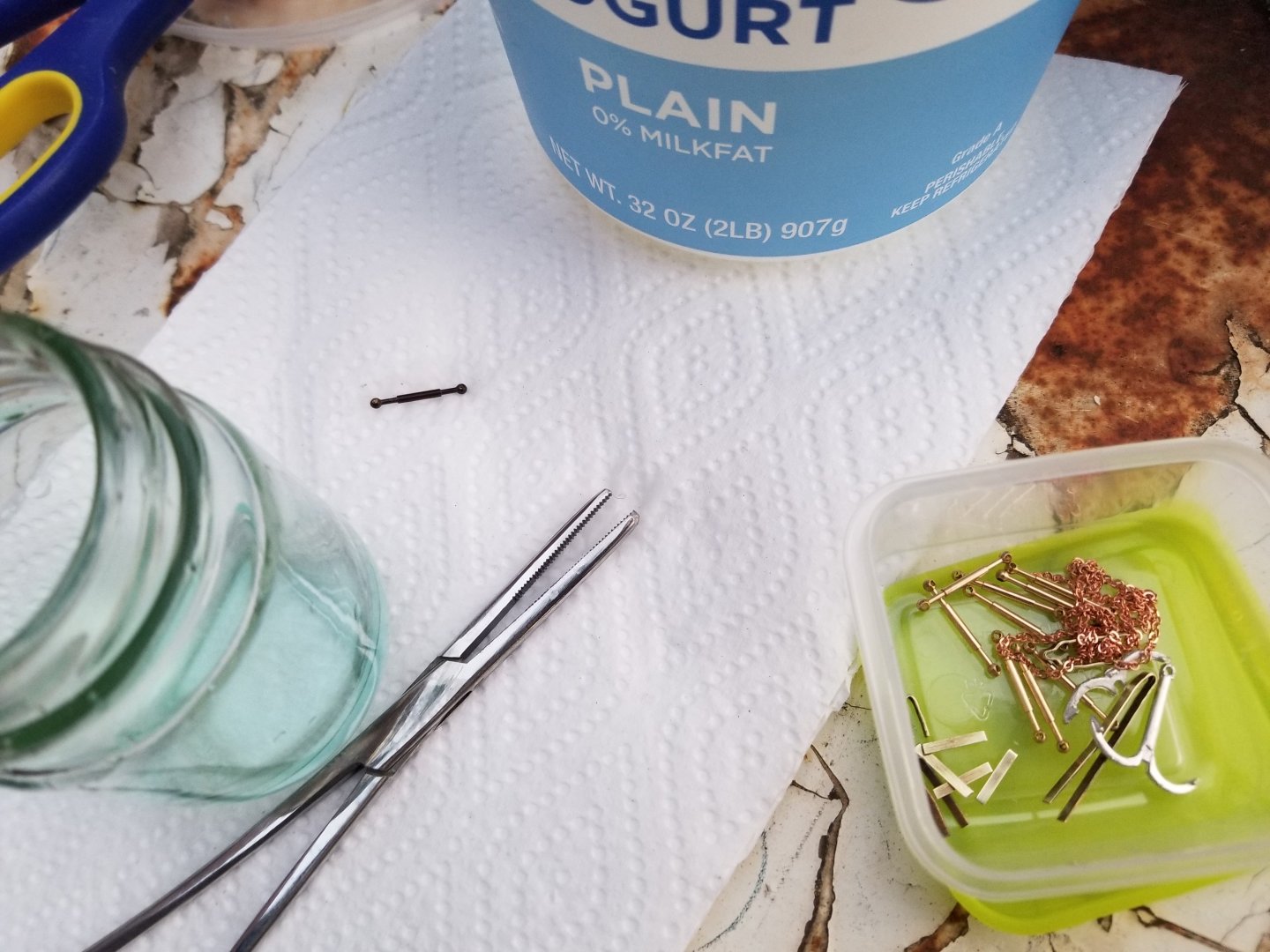
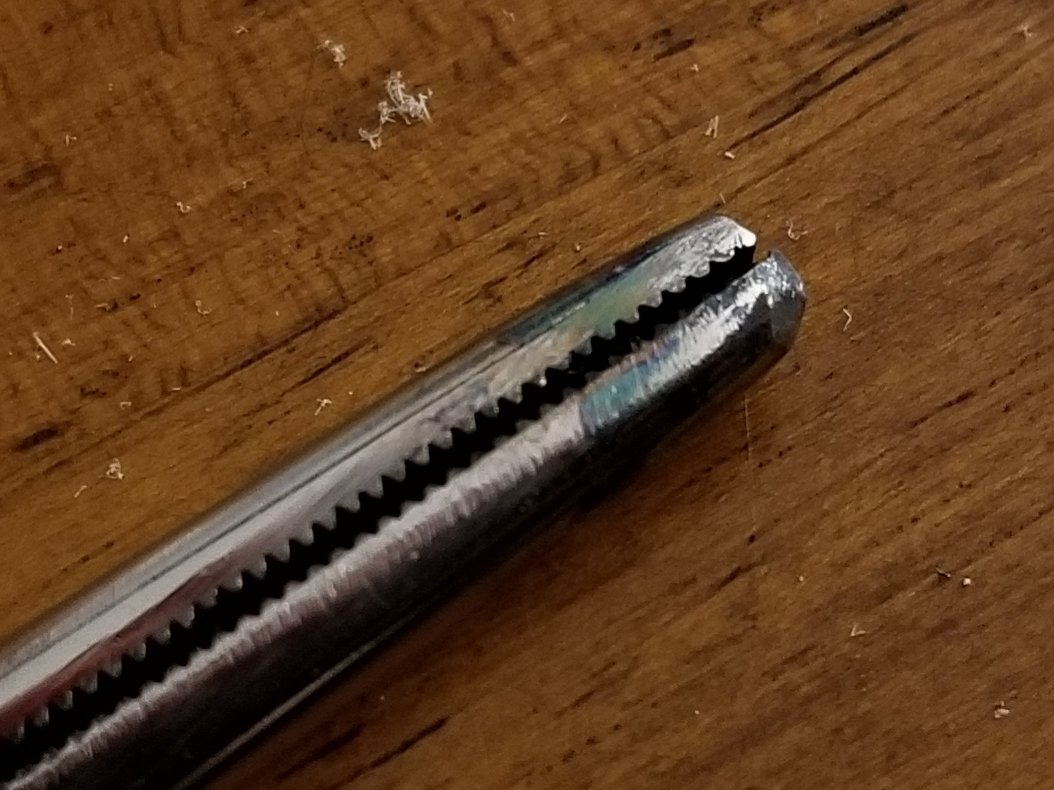
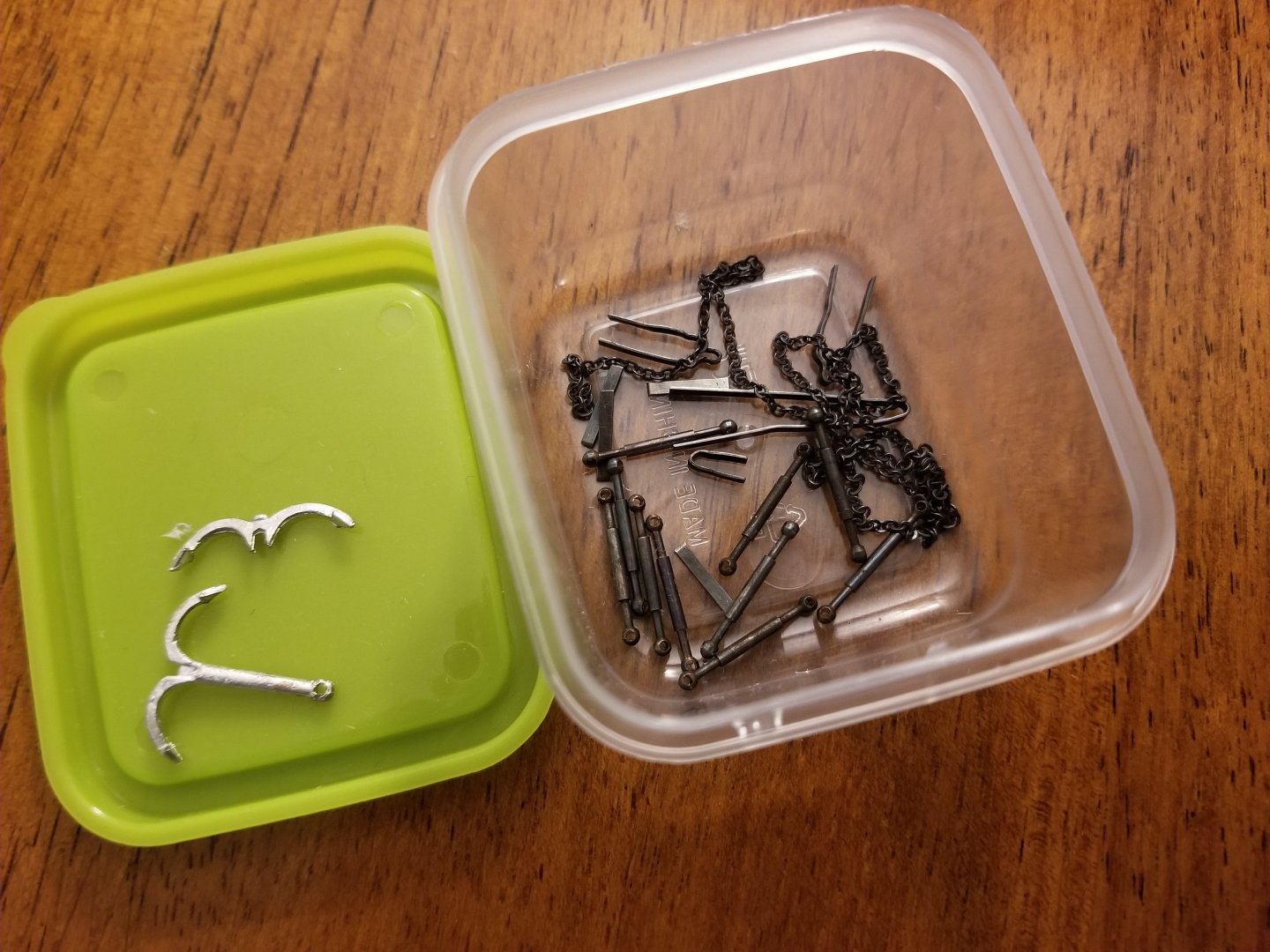
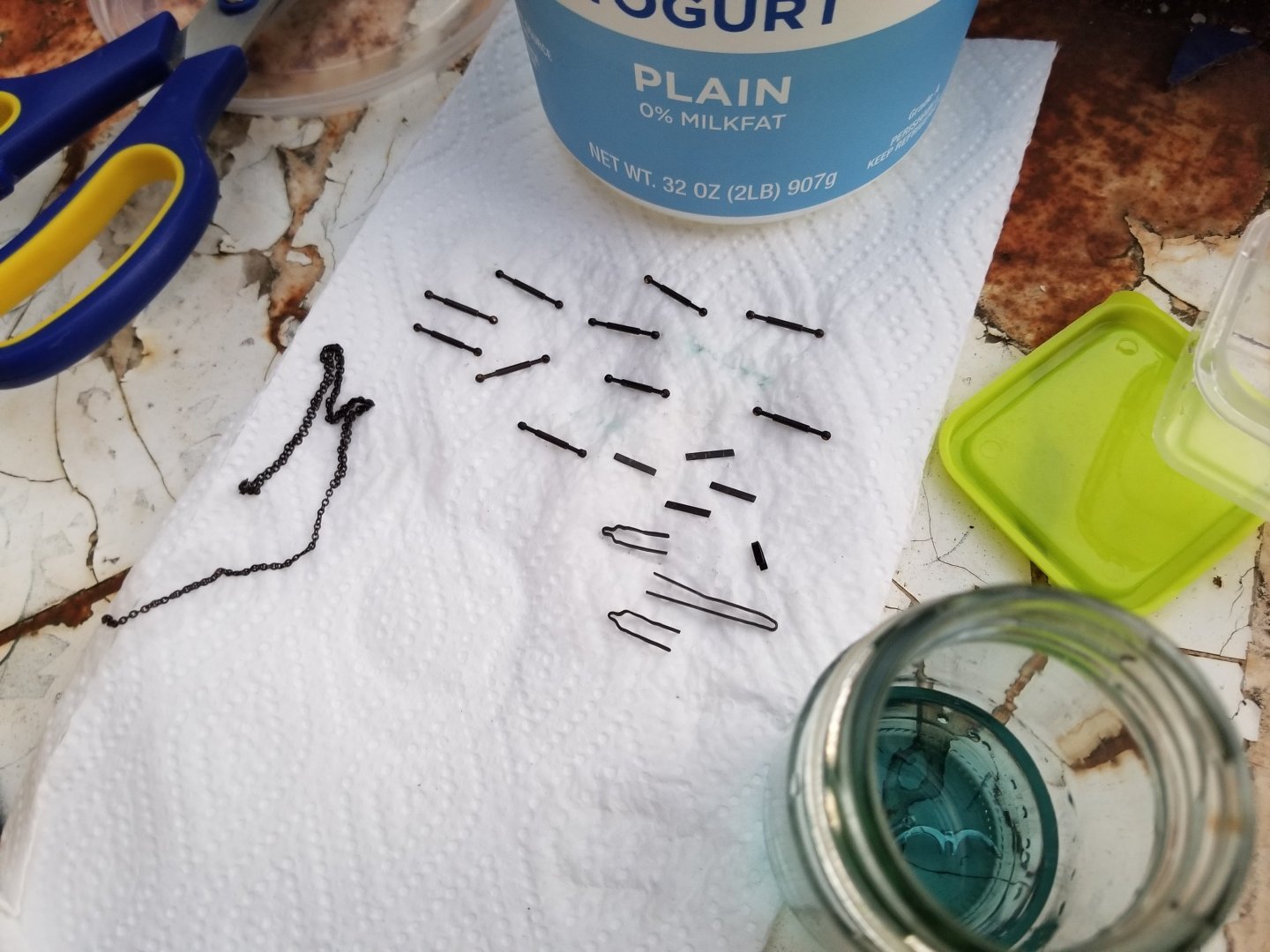
 I was able to make more progress today, this time on something that's been concerning me for a while--blackening metal parts. Thanks to the advice contained on this forum, I was able to get results I'm actually pretty happy with, from a process I'd never done before that had been giving me anxiety. As mentioned in some earlier posts, I needed to find some way of dealing with several metal parts. The numerous parts of the rudder hinges, of course, but also I had bought a chain and a grapnel anchor. I won't be able to take the birchwood casey brass blackening solution when I move in a month, so I decided it was now or never. I also decided to blacken some Billings-brand turnbuckles that I bought for another project (the build log of which will have to wait until after the move). This would also be a bit of an experiment in blackening different types of metal. The rudder hinges and turnbuckles are brass, the chain copper, and the anchor some kind of white metal. Following the advice contained in a number of build logs and other posts, I first set out to thoroughly clean all parts. (No photos of the cleaning, unfortunately.) The hinges, especially, were looking pretty grimy after having been repeatedly heated, reshaped, and handled bare-handed. I dunked all parts in a mix of distilled water and dish soap and gave them a good scrub with steel wool while holding them with a hemostat. This was a bit tricky as most of the parts are quite small--well, not that small compared with what some of you work with--and the steel wool tended to snag. In the future, I would like to try with a metal bristled brush instead. I then rinsed the parts off in distilled water. At this point, the rudder hinges looked notably better than before, but still not as shiny as the turnbuckles. I should note that I was wearing rubber gloves for all of this. The next step in cleaning was to give all the parts a soak for 10 minutes or so in isopropyl alcohol. While acetone seems to be usually recommended, I don't have any and didn't want to buy extra stuff before my move, and I had read some things saying isopropyl alcohol can work too. I then placed all the parts on a paper towel to air dry. Next up was the blackening itself. I set up on my balcony so that I would have good ventilation, and I used a small glass jar (previously full of curry paste, but well cleaned) to hold tye blackening solution. I had read that the blackening solution works best with a long soak in a mixture of around 6:1 water:blackening solution. However, as I don't have medicine droppers and was pouring directly from the containers, I accidentally ended up with something closer to 3:1 or 2:1. I considered diluting with more distilled water, but decided against it, given that you're supposed to only add acids to water and never water to acids. I dropped in one of the turnbuckles. It was amazing to see how quickly it turned black, and I fished it out with the hemostats after about 10 seconds (clearly my solution was not as distilled as it should have been), dunked it in an old yogurt tub of distilled water, and put it on a paper towel to dry. Below, my first blackened metal piece, left, and a little plastic container holding the parts to be blackened, right. I continued, giving all the parts a soak of 10-20 seconds. Below, I just had a single turnbuckle to go. The rudder hinges and chain seemed to blacken pretty well, as well, as can be seen below. The anchor, in contrast, did not blacken at all, even with a fairly long soak (in fact, it's sitting in the solution in the photo below). I had read that white metal didn't necessarily blacken, so I wasn't totally surprised. Interestingly, as can be seen, the color of the solution seemed to darken, especially after the copper chain (which blackened well). This does make me wonder whether a fresh solution would have blackened the anchor. All the blackened parts were, as can be seen above, very dark black in color, but this was actually a fine powder that needed to be removed (selenium, if I remember correctly, which is toxic--the gloves stayed on all through this process). I used another paper towel to buff all the parts. Given how small they were, and how tricky it was to have fine motor control with the gloves, I ended up just rubbing them between two paper towels flat on the table. (I then sealed the paper towels in a plastic bag to throw out, as a precaution.) As can be seen, the parts except for the anchor turned out a sort of gunmetal gray, which I think is quite nice. Looking more closely, I can see a few issues to improve upon in the future. The interior of the holes in the turnbuckles didn't consistently blacken because they usually trapped air bubbles when I dunked them in the solution, and even agitating them didn't always get the bubbles out. This shouldn't be too visible, though, once rope is tied to the turnbuckles. There's also some unevenness in coloration, due either to my having cleaned the parts poorly or to my solution being too strong and not being able to do a long, slow soak. That said, this issue isn't really visible unless you look at the parts from very close up (for size, the turnbuckles are 11/16 of an inch in length). So, while there are things I could do better, overall I'm pleased with how these parts turned out. I will definitely feel more confident next time I blacken metal parts (whenever that may be). I should note, too, that my hemostats--which I thought were stainless steel--also ended up a bit discolored from this process. For now, I'm going to think if I have any other metal parts to blacken. I'll let the blackening solution dry out, and then will carefully through out the residue. Also, I tried to superglue the anchor pieces together as a prelude to painting, but the glue didn't stick at all. Clearly I'll need a different glue, but that can wait until after the move.

-
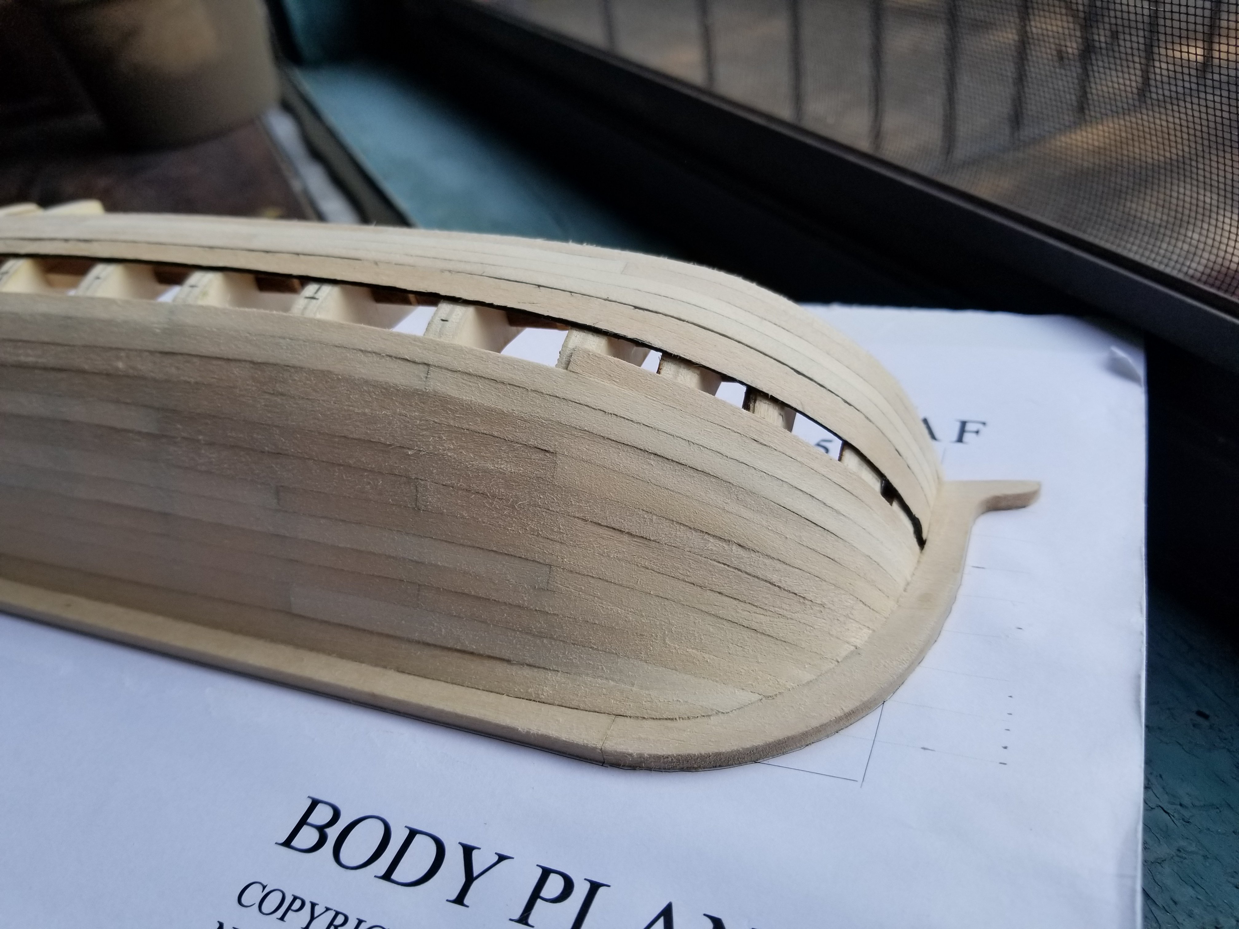
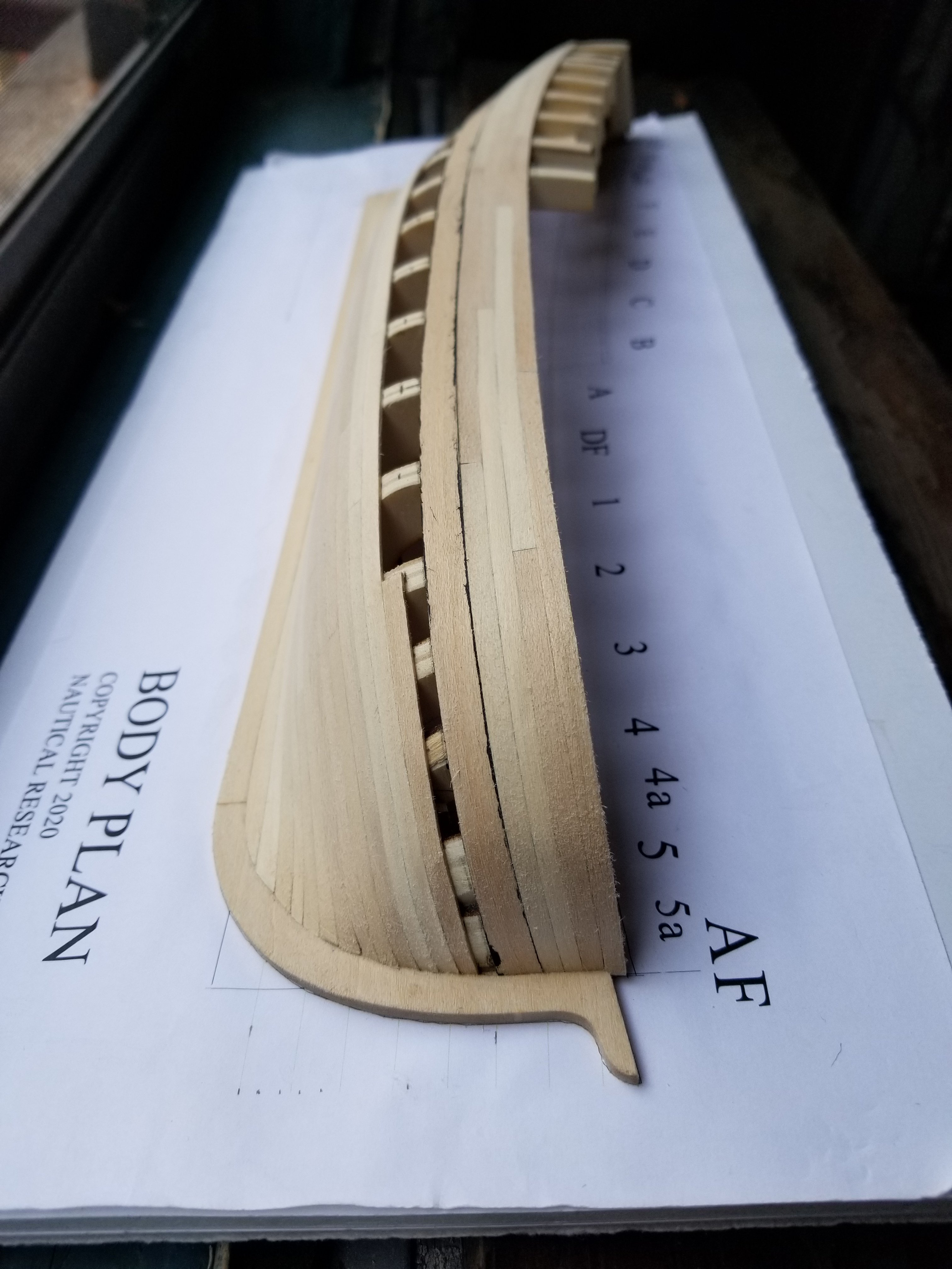
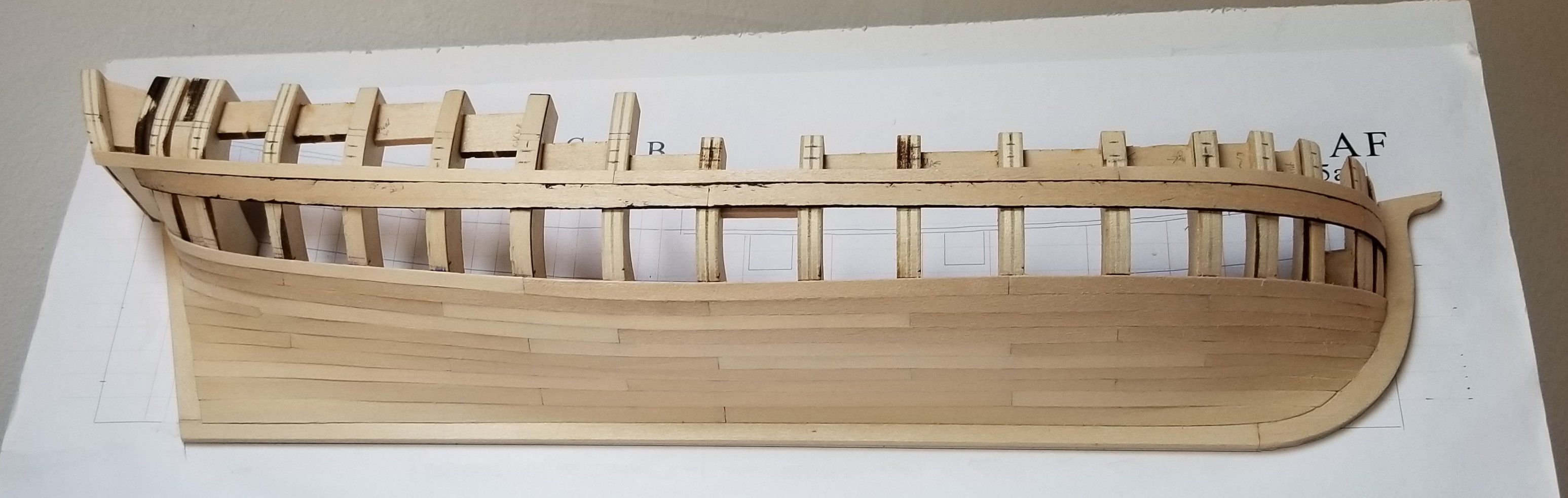
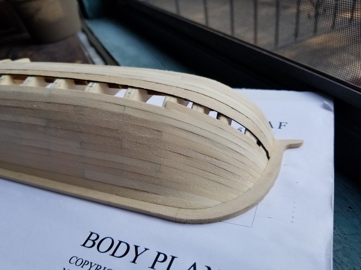
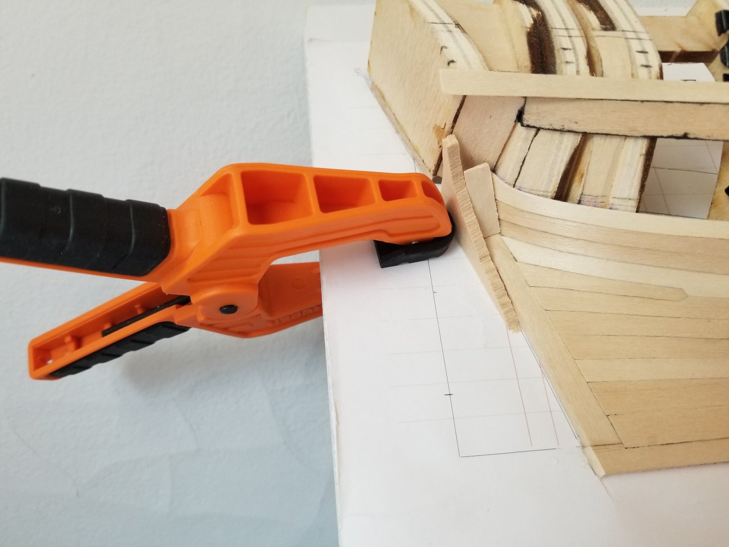
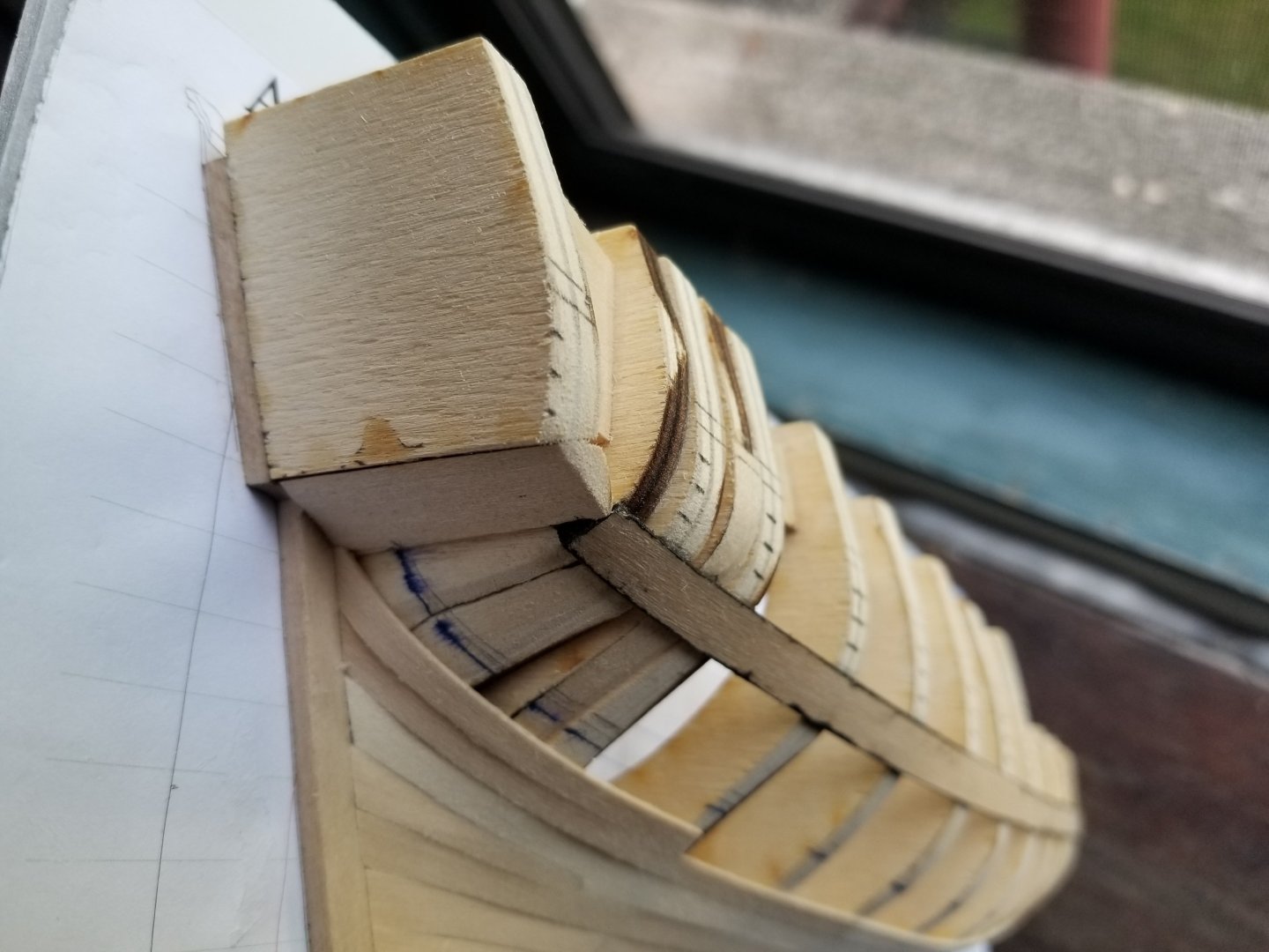
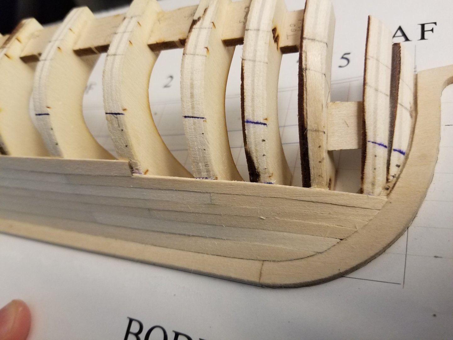
Not much that's new, just continuing with planking. I've finished the band above the wale, and have started the second-to-last strake in the last band below it. Clamping has been difficult due to the narrow space. And here's where it currently is: Close-up photography really brings out all the errors at the bow: In any case, I'm hoping to finish in the next couple of weeks.


- 82 replies
-
- 8
-

-
- half hull planking project
- half hull
- (and 2 more)
-
Amazing job, congratulations on an excellent build! Thank you as well for doing such a thorough job of documenting your process, this log is an excellent resource.
- 562 replies
-
- 4
-

-
-
- vanguard models
- alert
- (and 2 more)
-
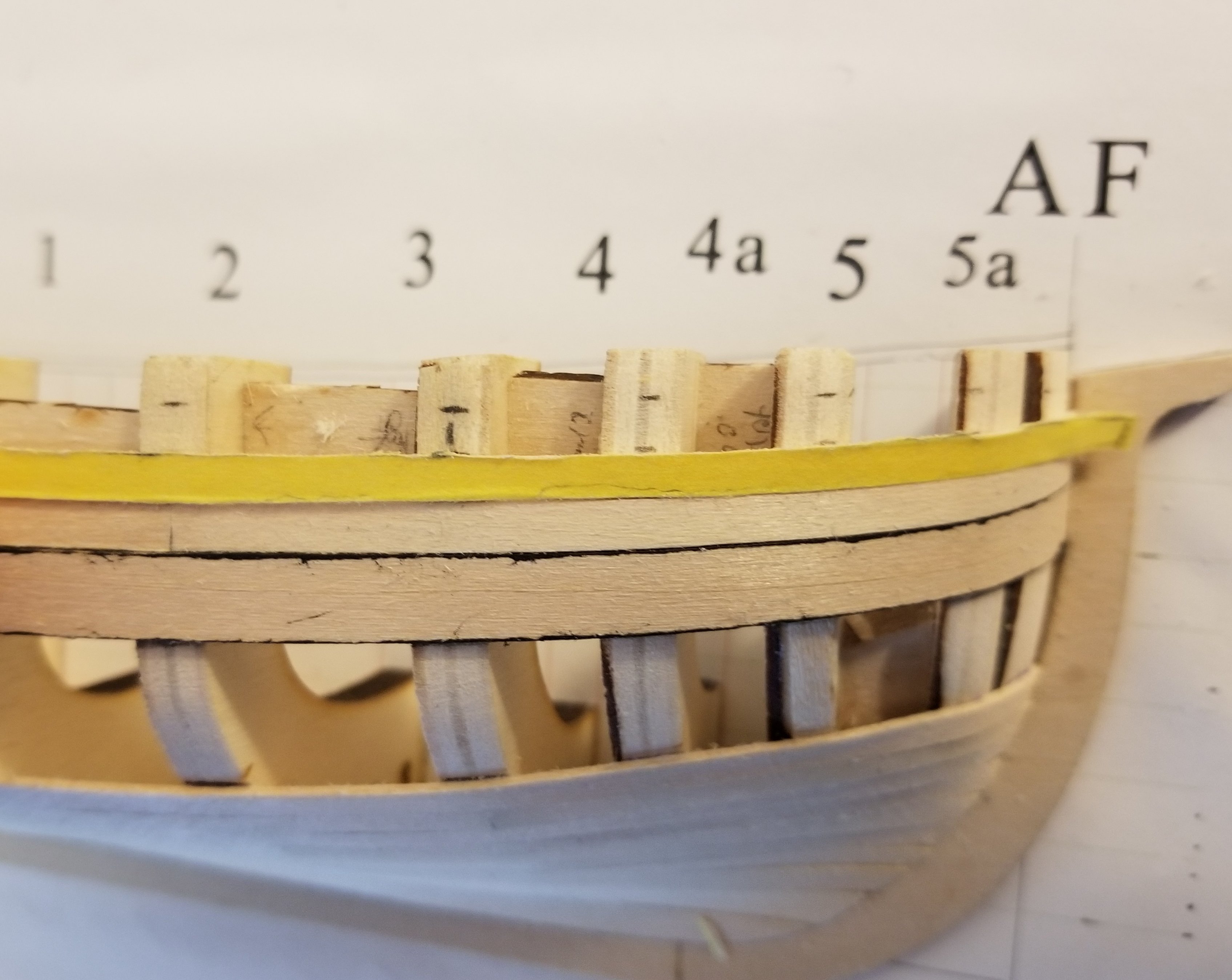
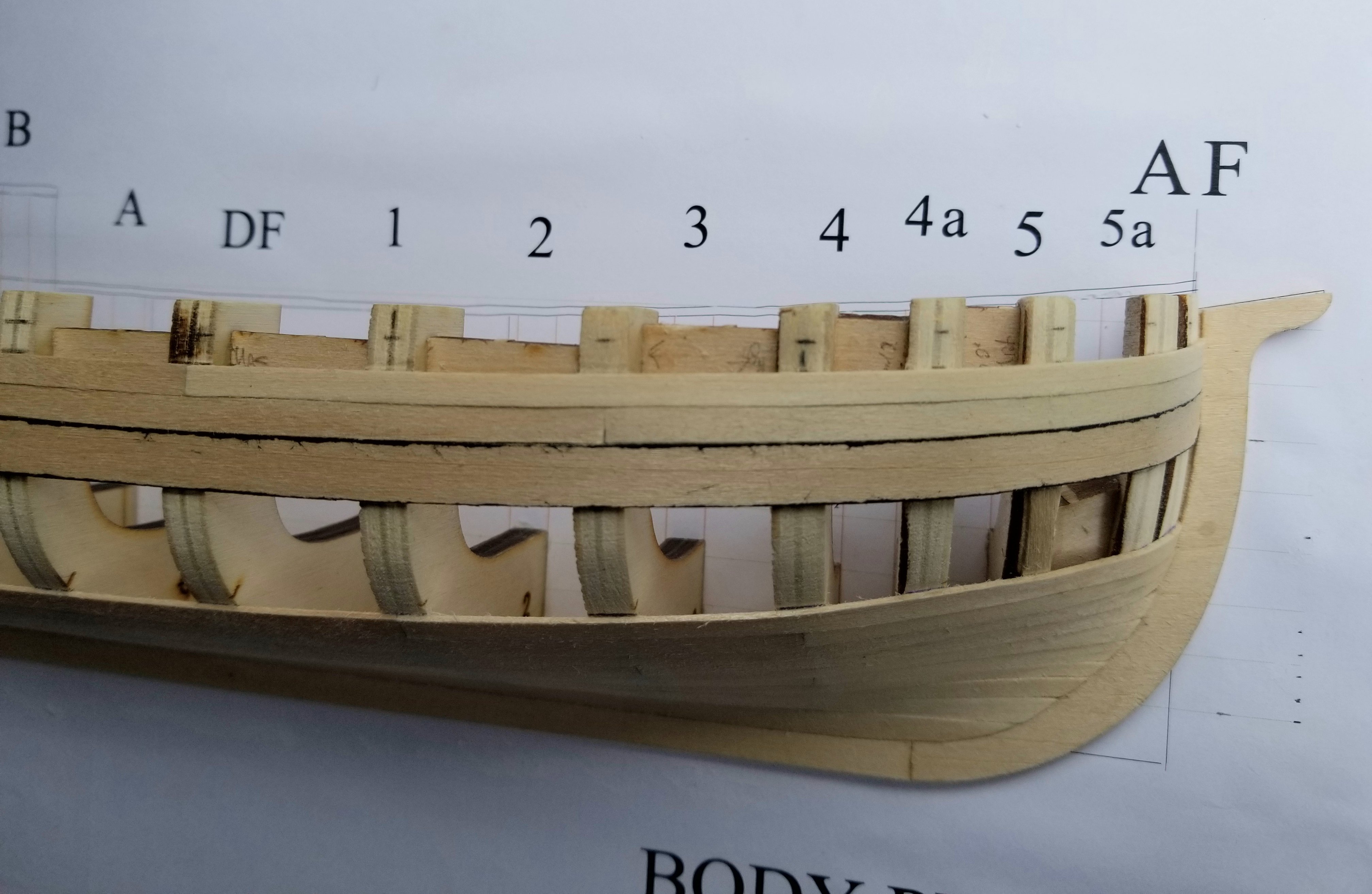
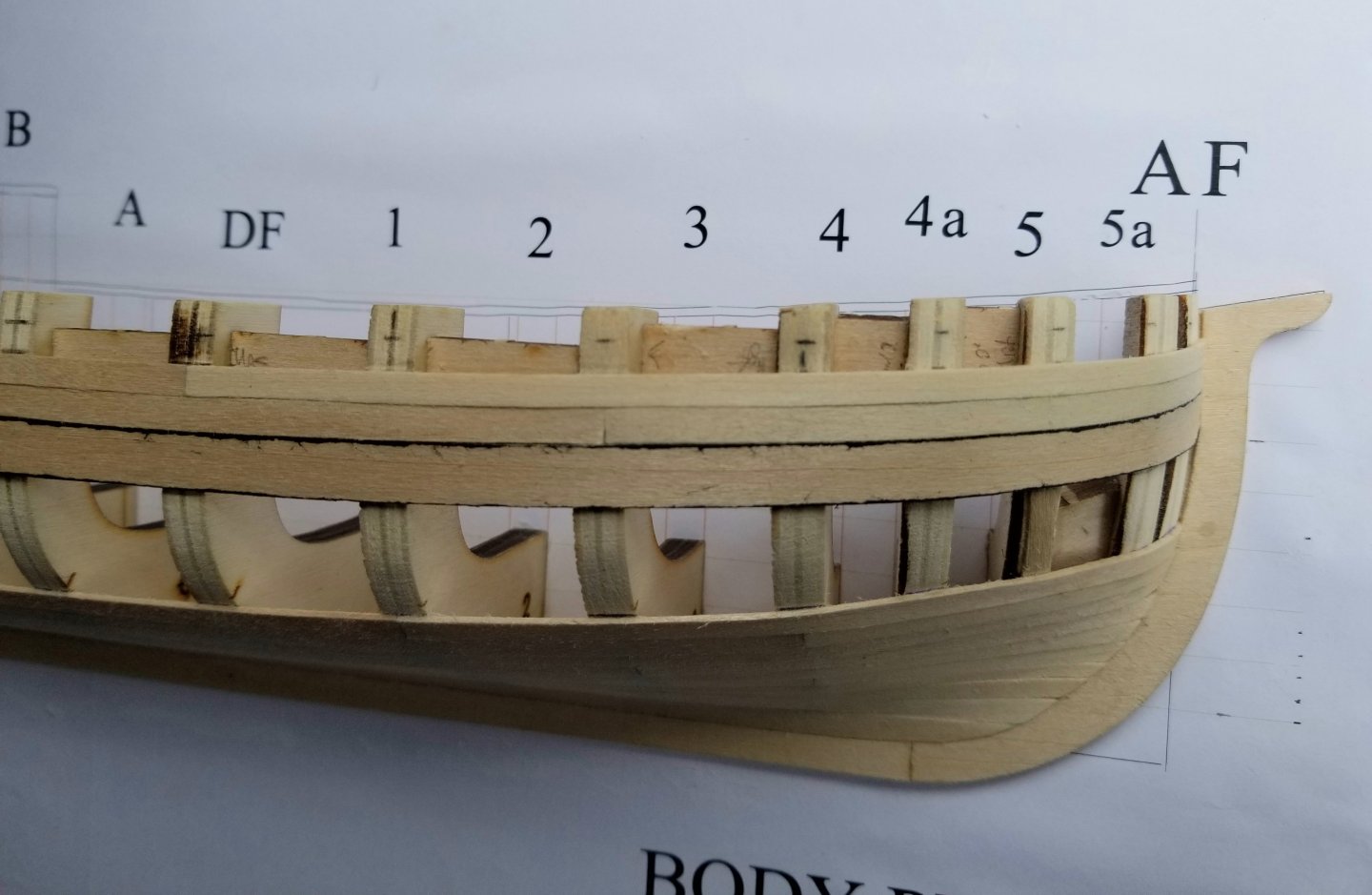
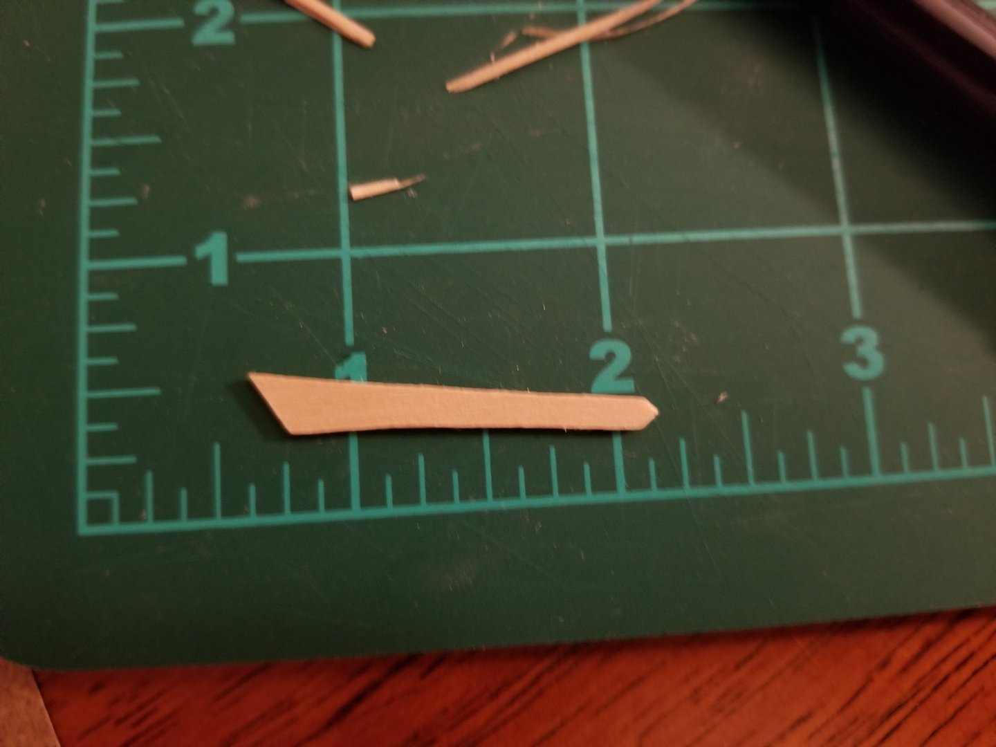
Thanks, that's very kind of you! That said, I can see a lot to improve upon in future builds. It's important to note failures as well as successes, in order to (hopefully) learn from them. For instance, I trimmed this plank too thin while I was shaping it. You can see how several marks are well above the plank: This was because I was using a dull exacto blade to trim it. Instead of cutting smoothly, I took a divot out of the wood. I feel like blade dullness is an issue that always sneaks up on me and I don't notice it until I have an issue like this. In any case, I swapped blades and redid the plank. It's amazing how much better a fresh blade cuts. The plank looks much better now. That said, while the plank looks good, you can still see a little bit of the marking on frame 4a. As far as I can tell, if I follow the markings perfectly, they'll all be a little wider on that frame than on those around them. I'm a little confused by how this happened--maybe my wale is slightly low there? The run of the sheer appears smooth when I check it, so I don't think I left the frame too high. I'll see how it looks once I get the other two planks on.

- 82 replies
-
- 6
-
-
- half hull planking project
- half hull
- (and 2 more)
-
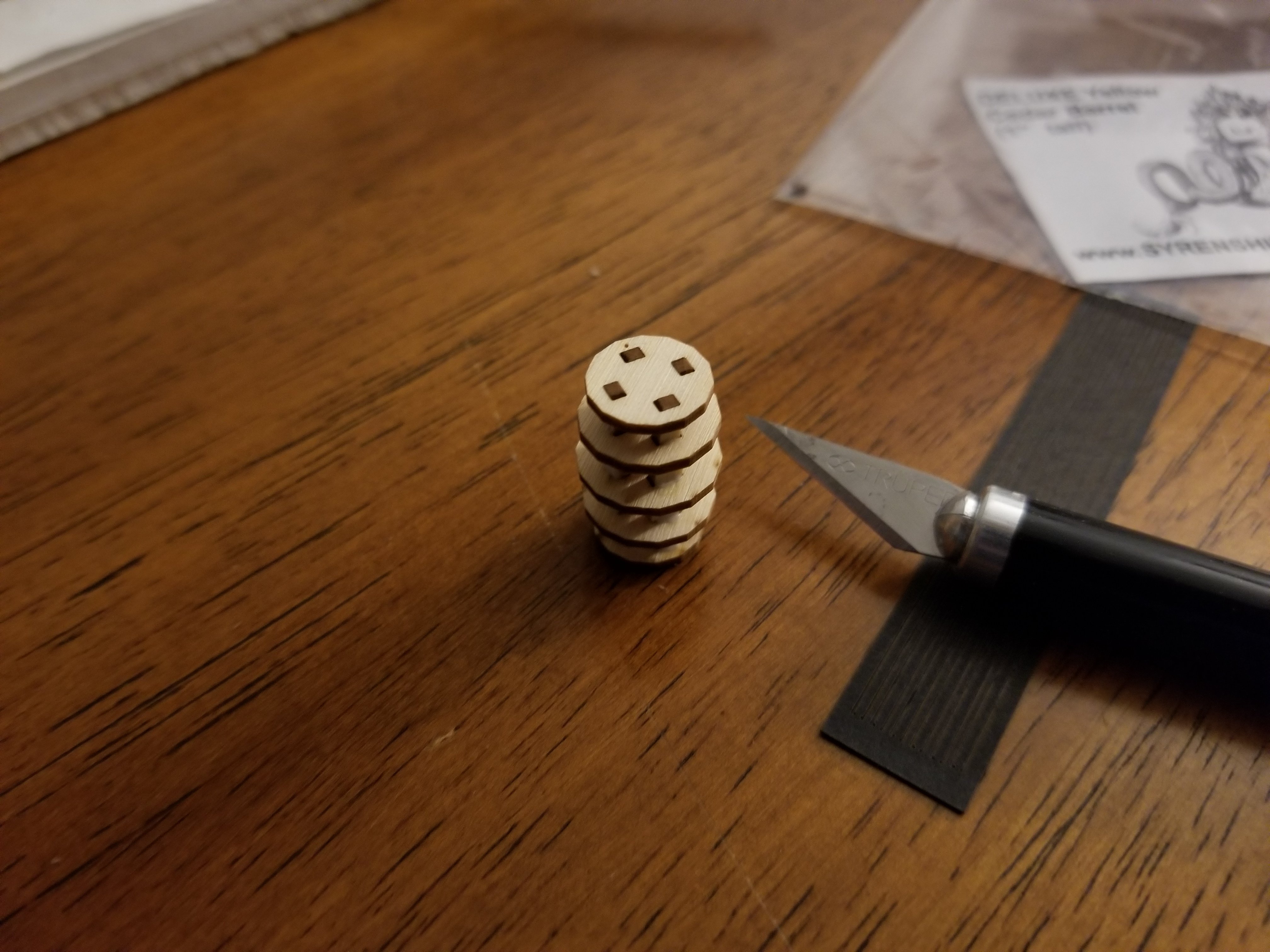
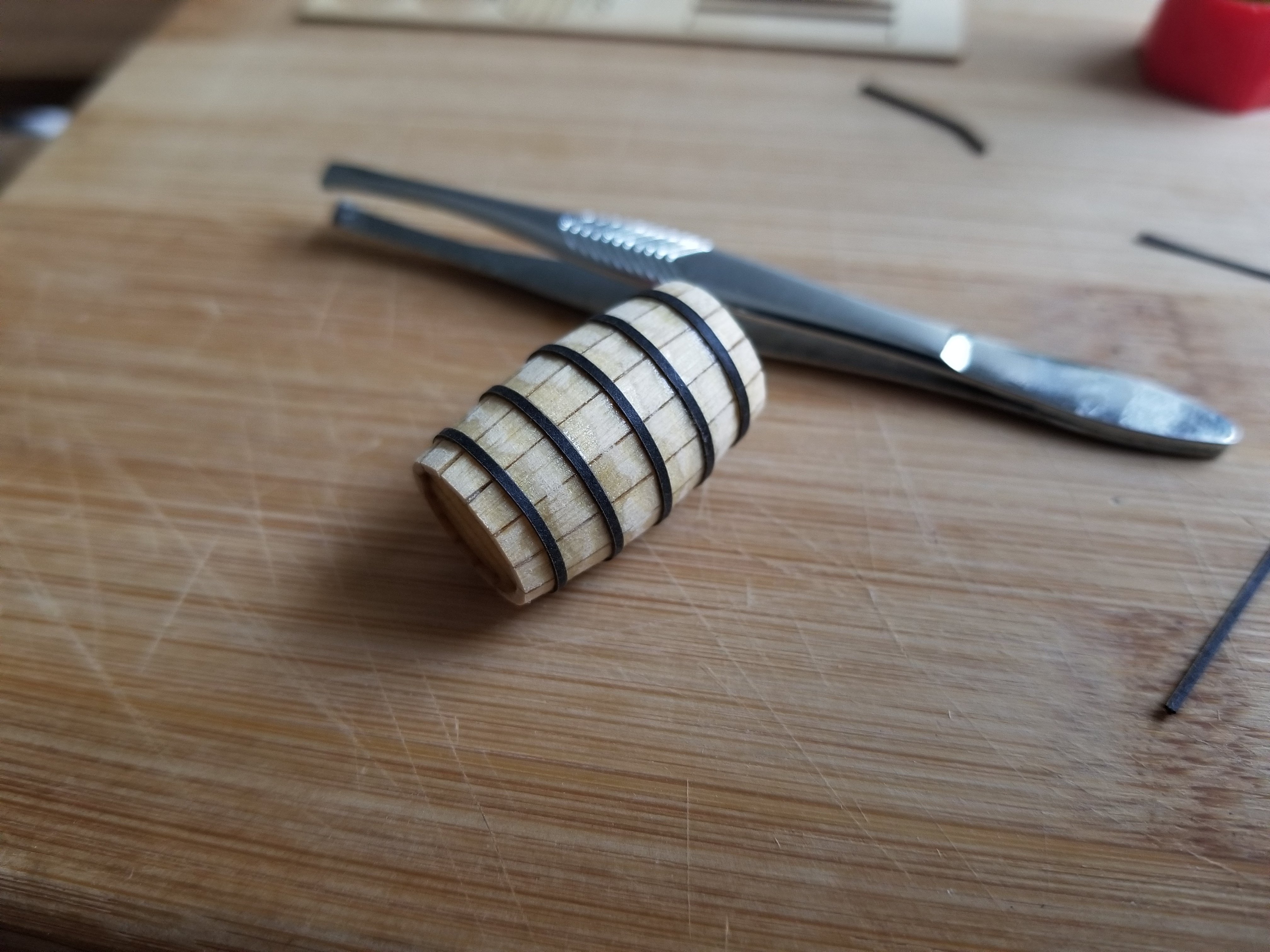
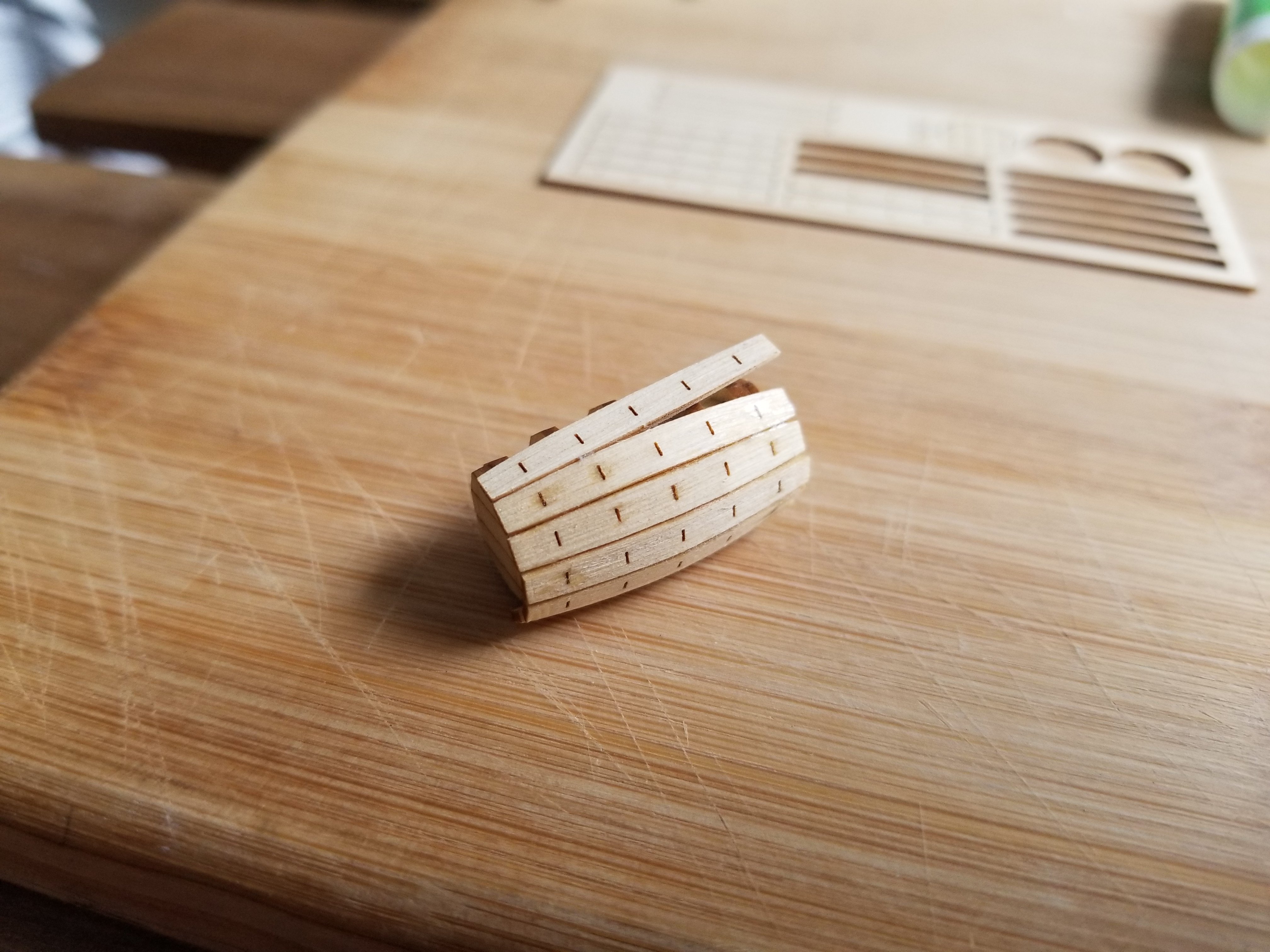
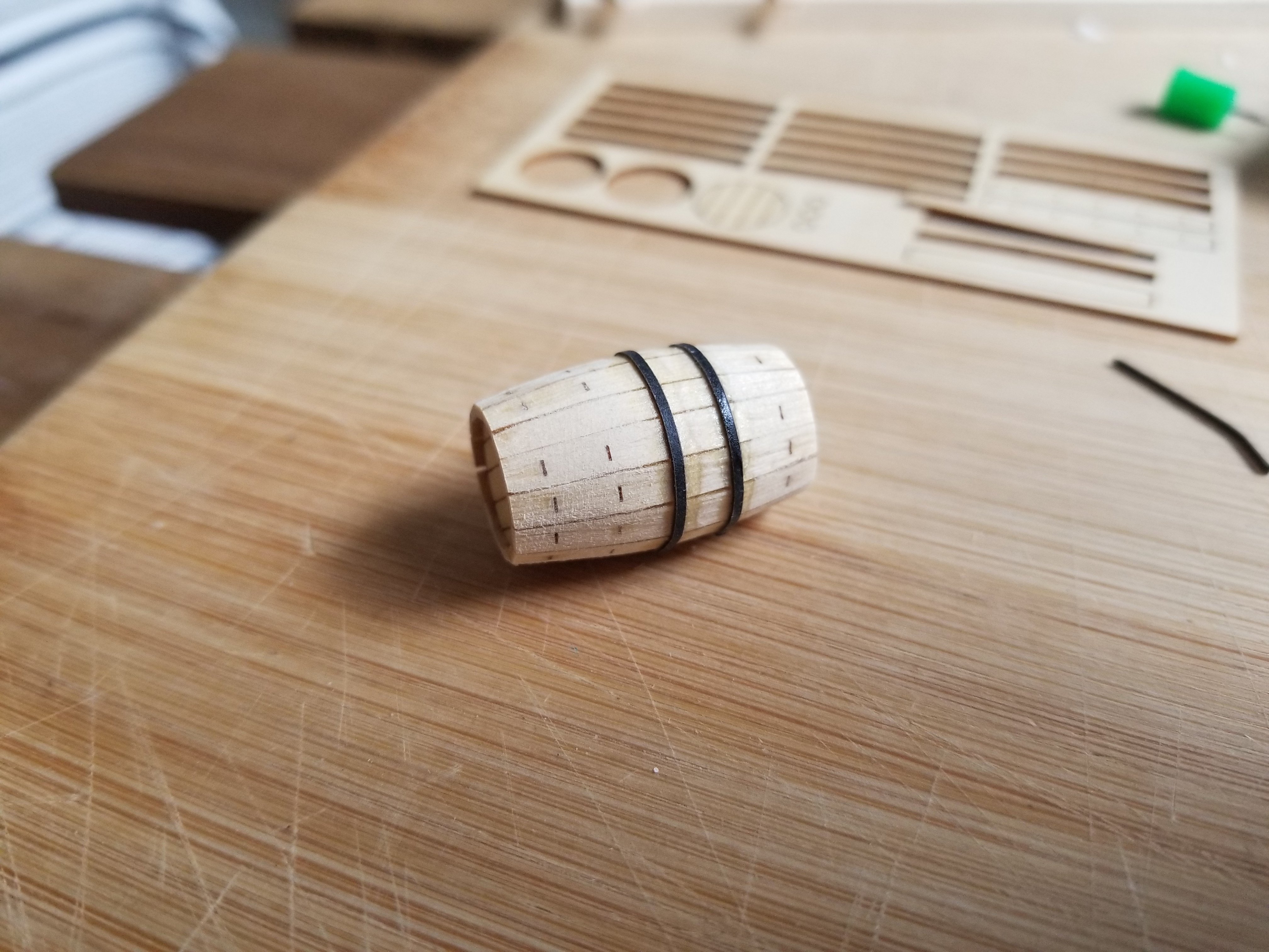
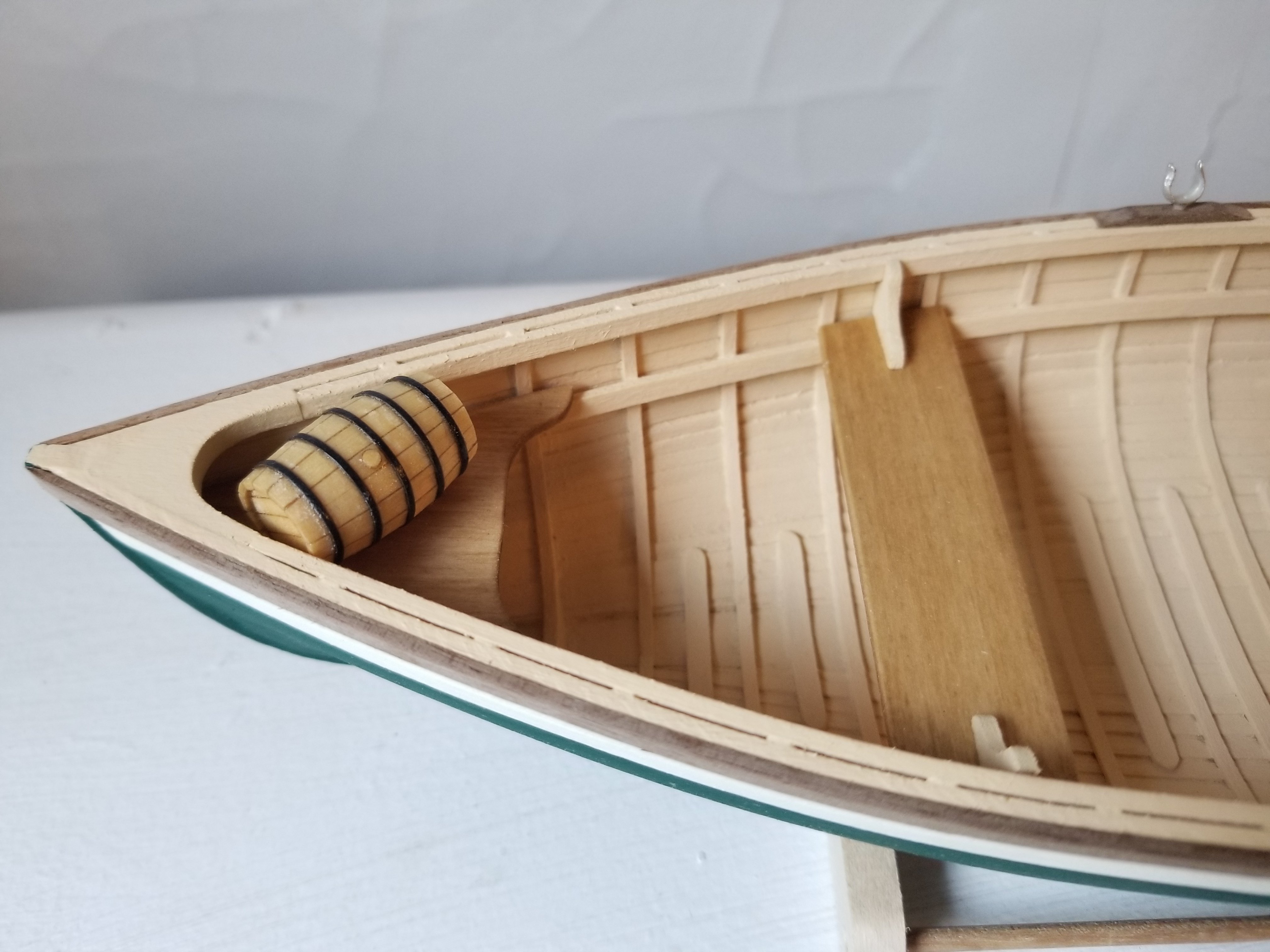
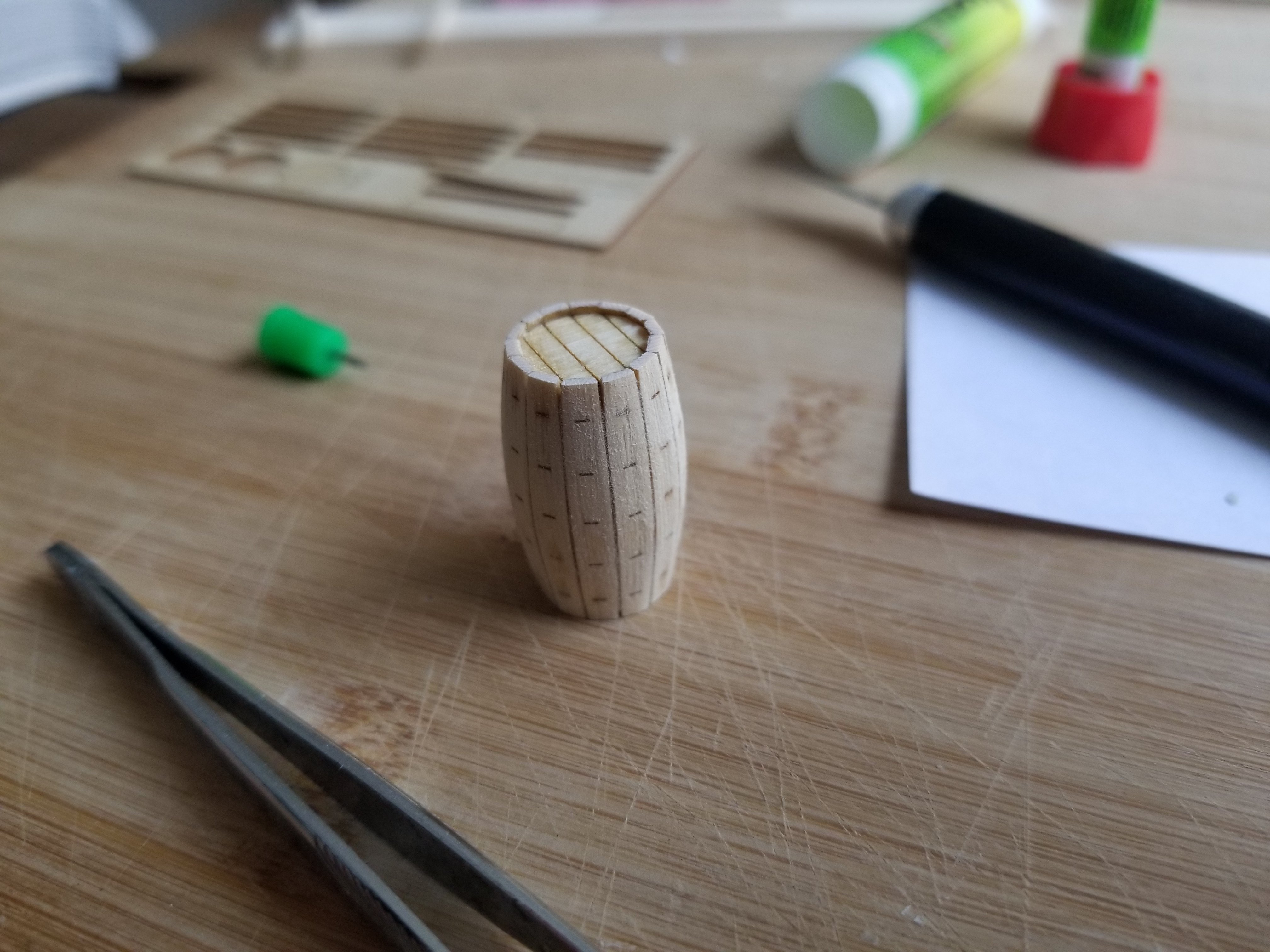
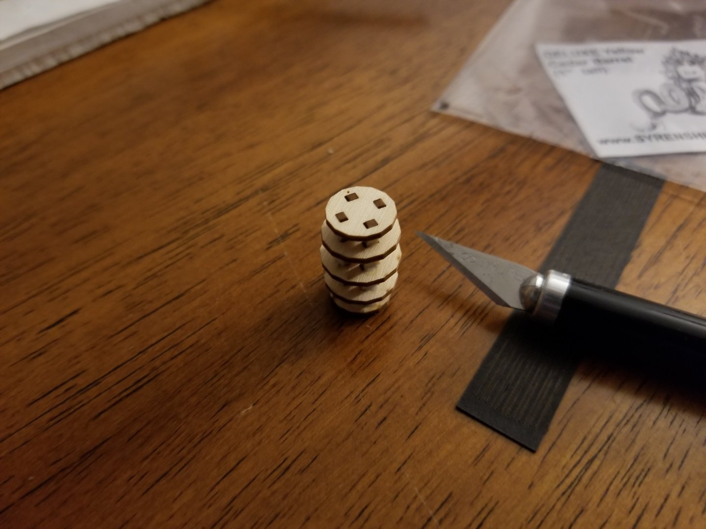
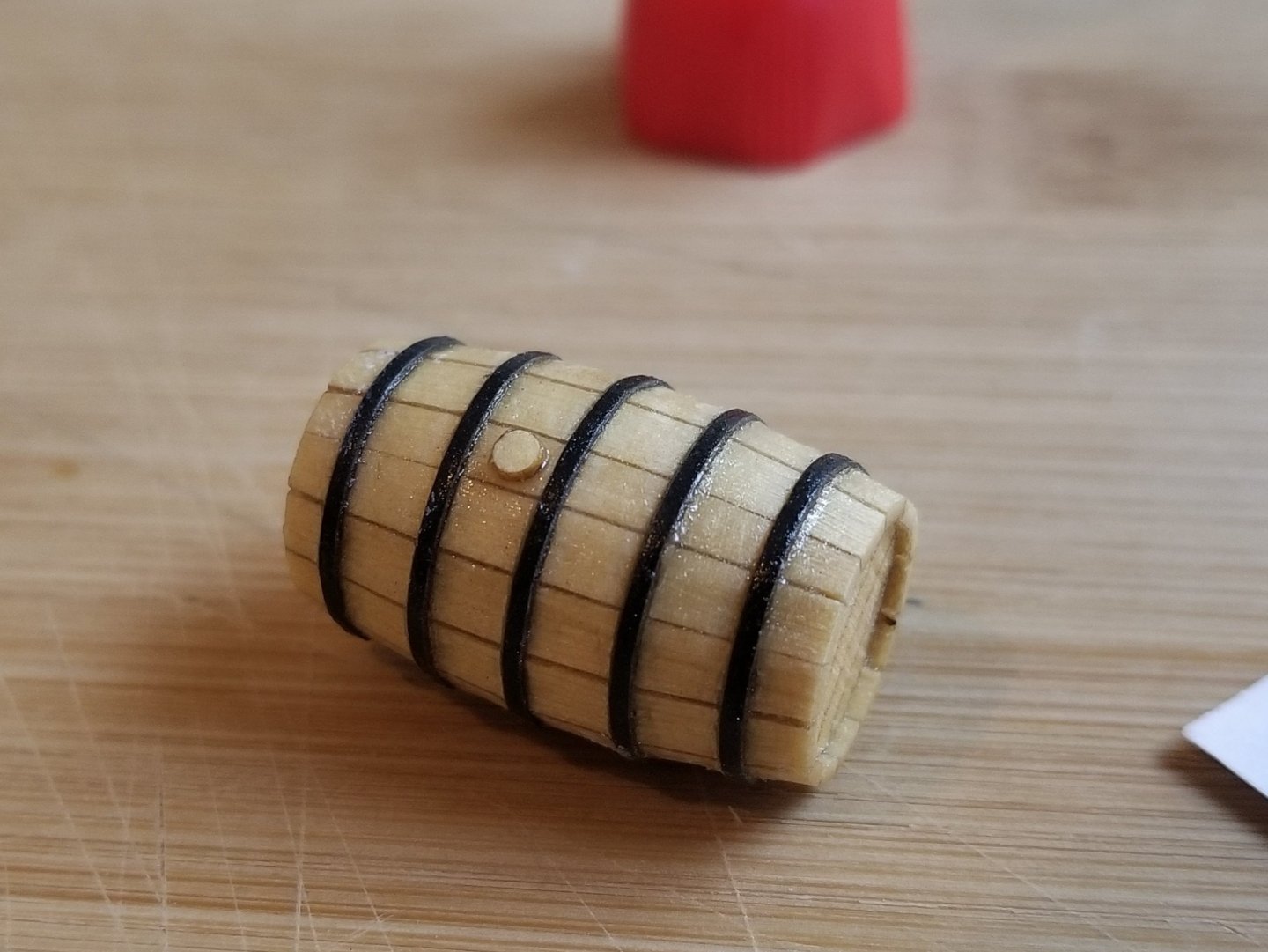
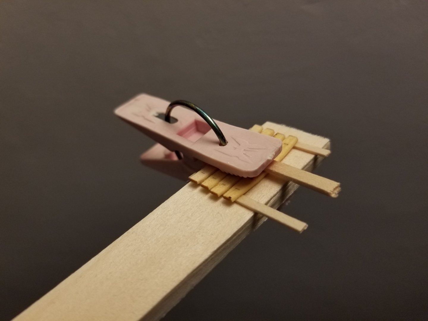
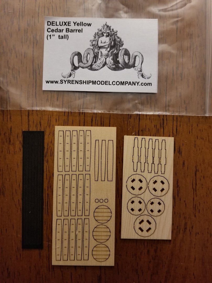
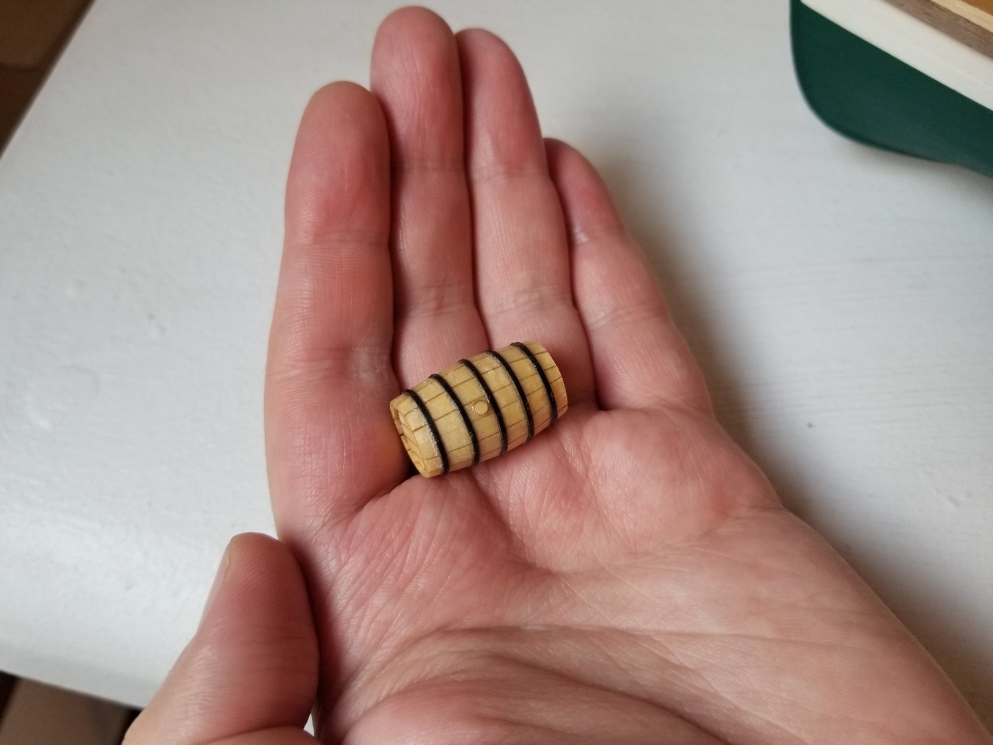
Although the Canoa itself is on hold for now, I thought I might make some of the gear and accoutrements that will bring the finished model to life. I decided to make a barrel, which might go into the Canoa or into a different model that I haven't started yet. I saw that Chuck Passaro sells deluxe barrel mini-kits (Syren Deluxe Barrels) that are made of Alaskan Yellow Cedar. I ordered a couple alongside rope and fittings for another build being planned. I've heard a lot about how nice Alaskan Yellow Cedar is to work with, but also that it can cause allergic reactions in some people, and I thought a tiny barrel kit would be just the thing to test whether or not I'm allergic to it. I also haven't seen many mentions of these on the site, so I thought a mini build log might be interesting for anyone considering them as an option. The mini kit is quite nice--you get two small sheets with laser-cut parts, and a sheet of laserboard for the hoops. The laser cutting is very precise, with no charring on the side that will be visible. The interlocking framework is quite simple to put together. Do make sure to line up the dots on the parts, otherwise the 14-sided edge won't match up. The instructions say the framework can just be held in place with friction, but I found it more secure to add a drop of glue to each joint. I then glued on the end caps and began work on the staves. These were tricky. They don't have to take that much of a curve, but they're just an inch long, making it hard to bend them properly. The instructions say just to use superglue and hold them in place while it cures, but no matter how long I held them, the ends popped off. The instructions say that trying to pre-bend the staves will just break them, but I decided to give it a try anyway, using scrap to make a simple jig, soaking the staves, and letting them dry overnight. None of the staves broke, but this also didn't work--the curve was too gentle, and the ends still wanted to pop off. Instead, what I found worked was to superglue one end of the stave firmly in place, wait for it to cure, and then bend it and glue on the other end. For whatever reason, this worked far better than trying to hold both ends in place at once. You can see an example in the middle of this process below. It took some time, and some glued fingers--I really do dislike super glue--but eventually all the staves were added and I smoothed the outside and ends. Next was to add the hoops. I did a very poor job of keeping these even, but I think it's not so noticeable if the barrel is stowed in a hold. As can be seen, the superglue stained the wood, leaving the barrel very blotchy. I ended up simply spreading a bit of super glue over the whole barrel to give an even color. It did in fact bring out some of the richness of the wood, although it's a bit glossy. As can be seen, the barrel is pretty small. At 1:32 scale, this is a fairly small barrel, 2 ft 8 in tall. For now, I'm just stowing it in the bow of the Peapod (where it's basically a tiny cask) while I decide whether it will eventually go in the Canoa or one of two coastal traders I'll be building next. Overall I'm pleased with the barrel kit and would recommend it to anyone who is curious. Just keep in mind that curving the staves is a bit tricky, and be careful not to get superglue everywhere. Edit: I forgot to mention that it seems I am not allergic to Alaskan Yellow Cedar, which is great news although I'm not sure when I will ever work with it--at the moment, I have a decent supply of cherry, alder, and basswood for my upcoming builds and won't be buying wood for a while. I also should note that, with the extra pieces included in the kit, once I build the other barrel I should have enough spare parts to make a nice little bucket as well.


-
I'd also recommend posting a build log as the best way to get suggestions. This forum is a very supportive environment and you will receive help from people who would like to see you succeed. Moreover, a build log can show the full process, which can be helpful in understanding what went wrong. At the moment, I'm not totally sure why the wood is coming away from the hull like that, although I have a few ideas. What type of glue are you currently using? You may not be using enough, or are using too much, and may not be properly clamping it to cure. Also, when you soaked the planks to bend them into shape, did you allow them to fully dry, or did you glue them while they were still wet? If the latter, the plank may have shrunk once the water dried. There are a few things that stand out to me that could be contributing. First, you mentioned having only a few clamps. Having more clamps of different types would probably be helpful and make it easier to hold the wood in shape so that it more easily takes the bend. Second, maybe it's just the angle, but it looks like the planks may not have been spiled--that is, shaped, especially to reduce their width toward the bow. Spiling is frequently necessary to make sure the planks sit properly around the complex curves of the hull. If you click on the link in my signature to my NRG Half-Hull build log (or look at many other build logs for a variety of vessels) you can see how the planks become thinner near the bow, and are also cut into curved shapes to allow them to sit flat on the bulkheads around the curve. (Some prefer to use heat to bend planks sideways rather than cutting them into a curved shape.) Based on the amount of char on the bulkheads toward the bow, you also might need to fair more there, although you'd need to check this by using a thin batten to see if it can take a smooth curve while touching all bulkheads. These are just a few ideas, hopefully they are helpful. I do highly recommend making a build log.
-
Very well done, congratulations on finishing an excellent and highly original model! I've greatly enjoyed following along on this build, and look forward to whatever you build next--for whatever it's worth, my vote is for that tiny ferryboat with its bargeload of wagons.
-
Very nicely done, such clean worksmanship!
- 201 replies
-
- 5
-
-
-
- Oyster Sharpie
- first scratch build
- (and 1 more)
-
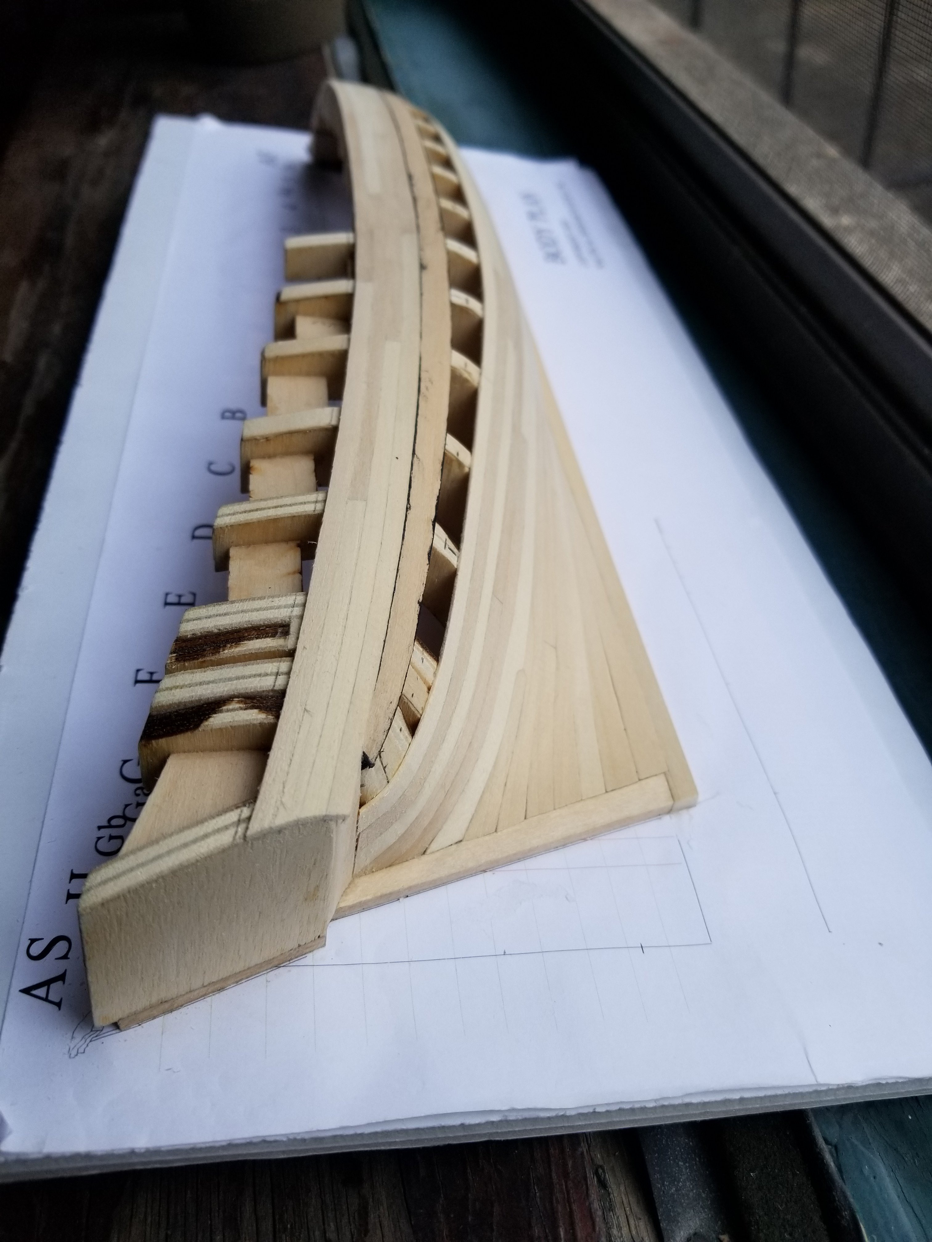
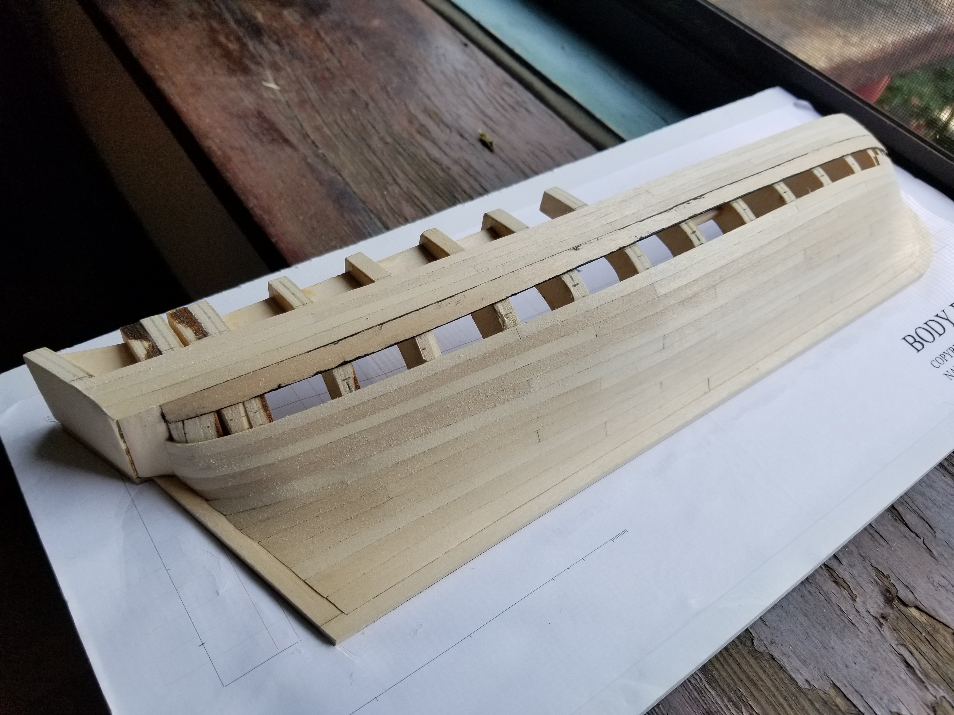
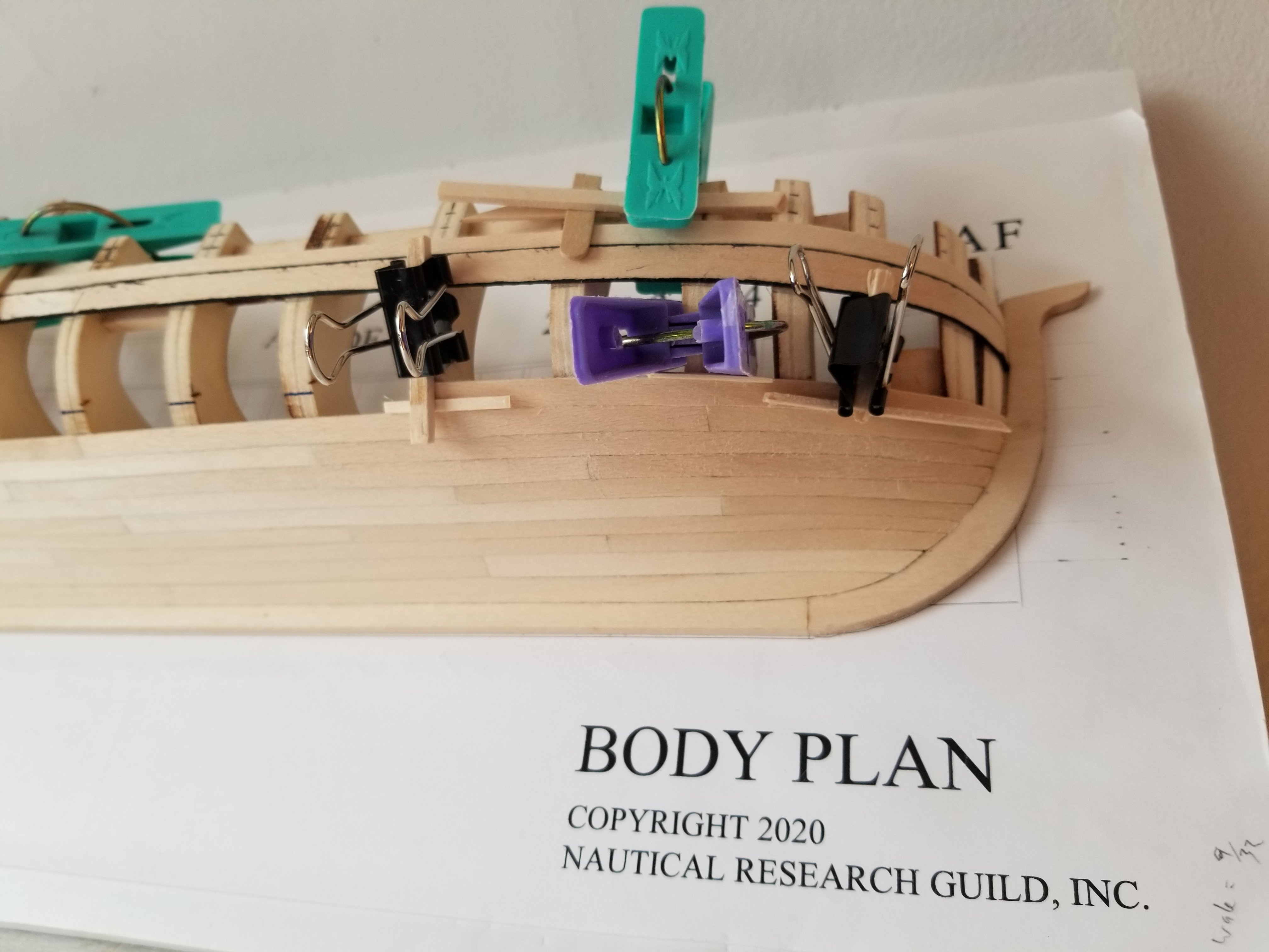
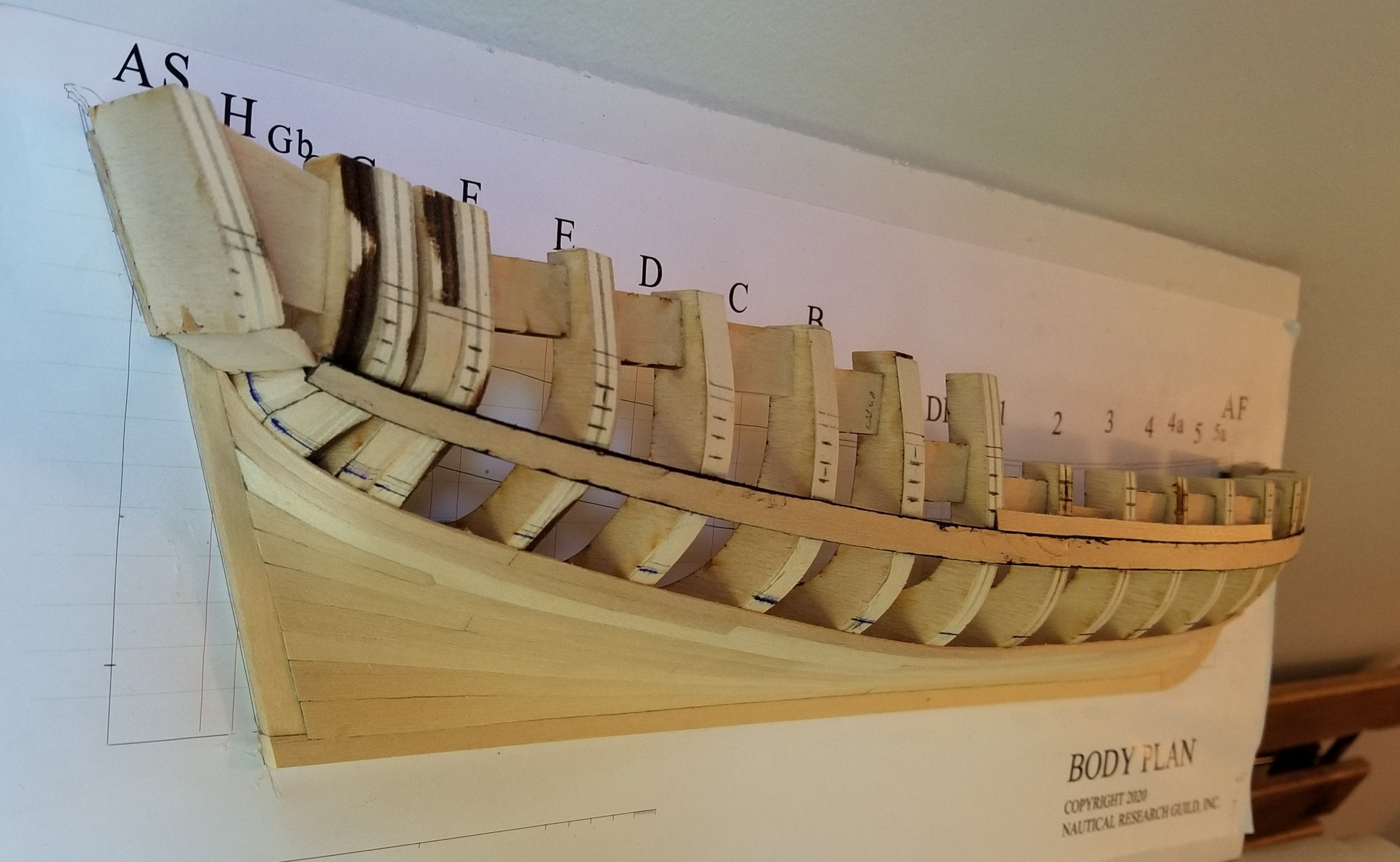
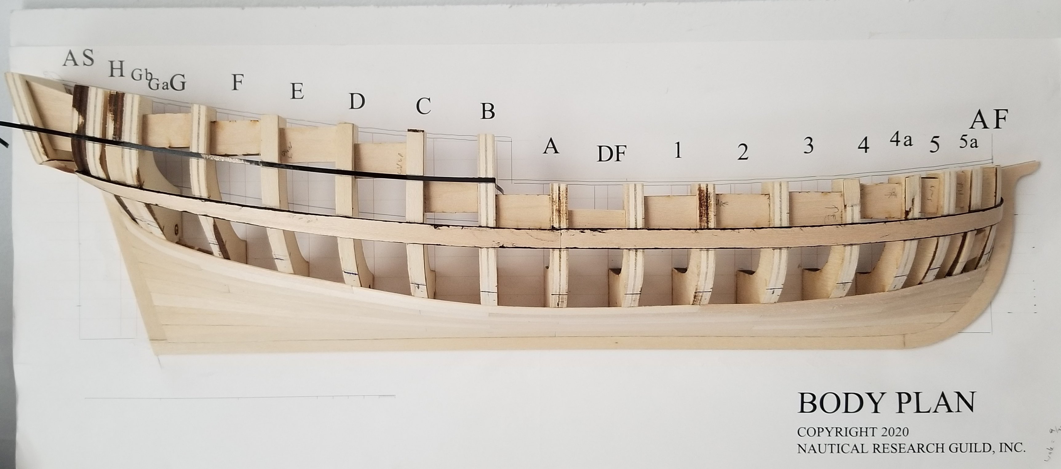
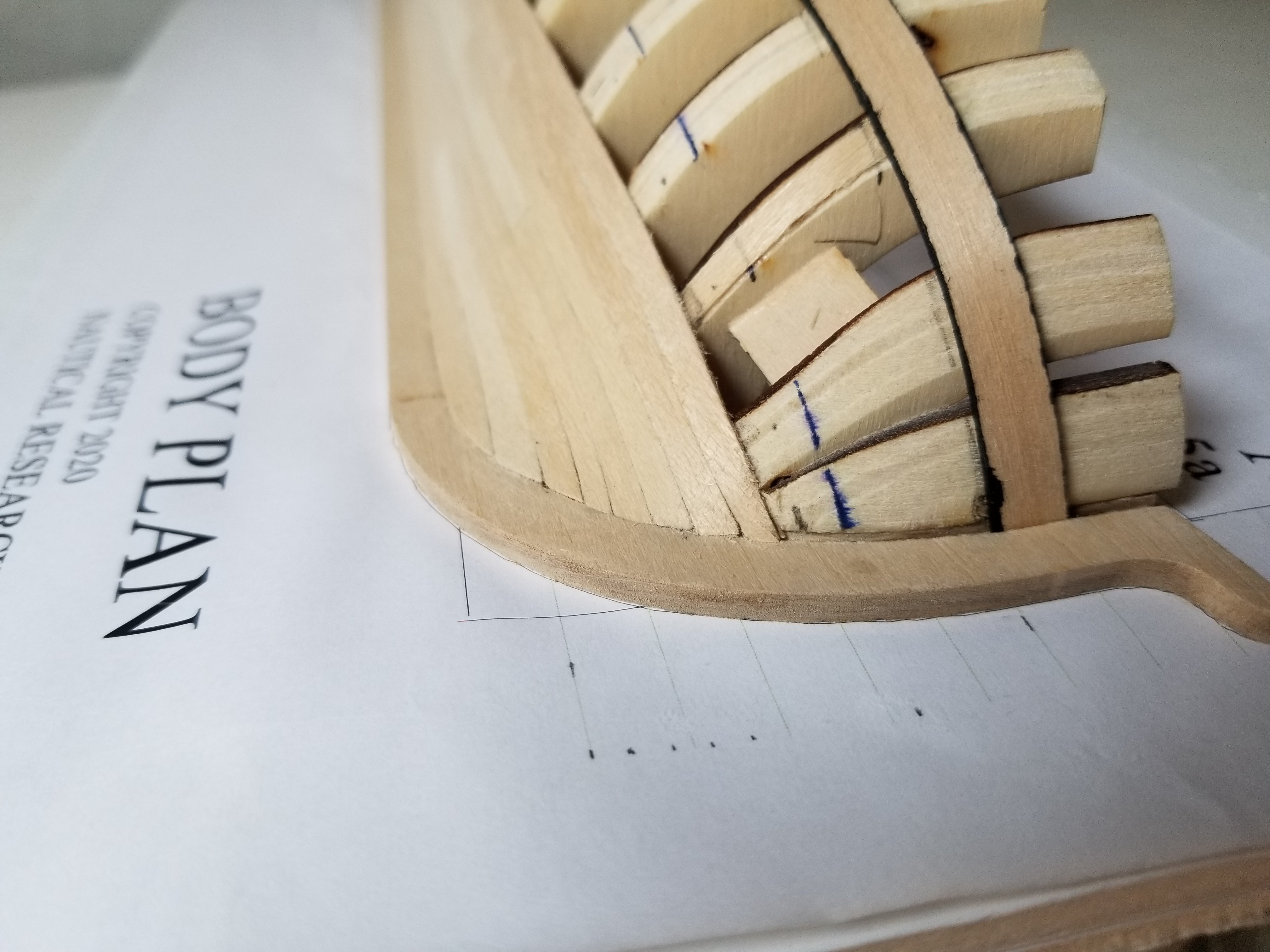
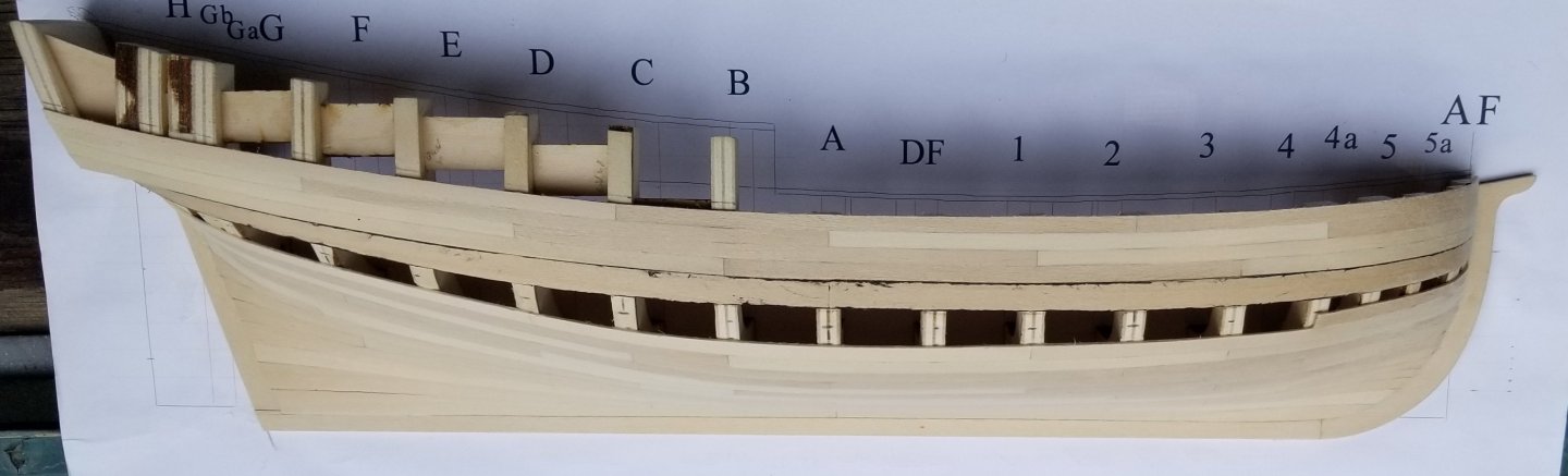
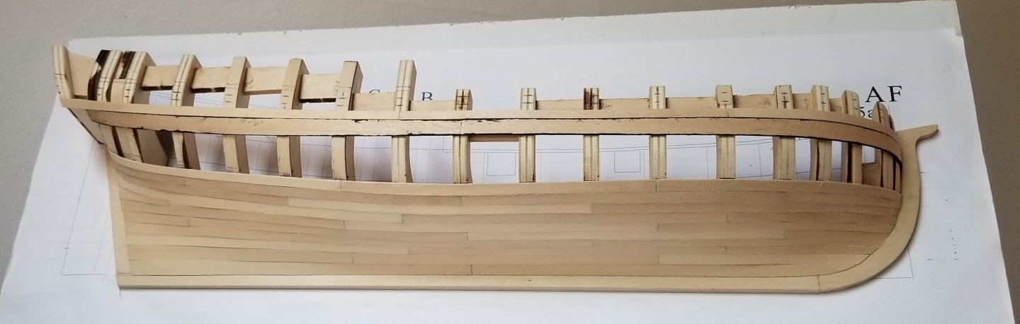
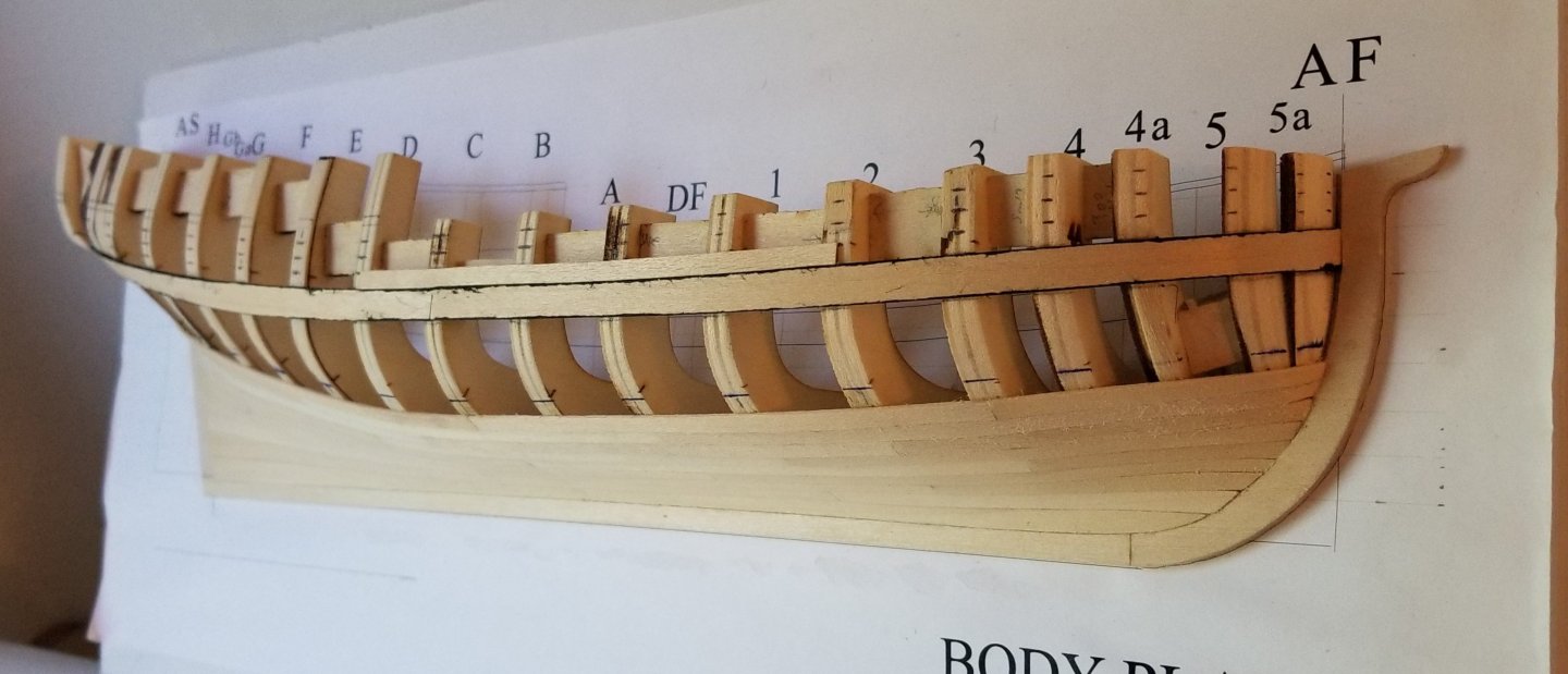
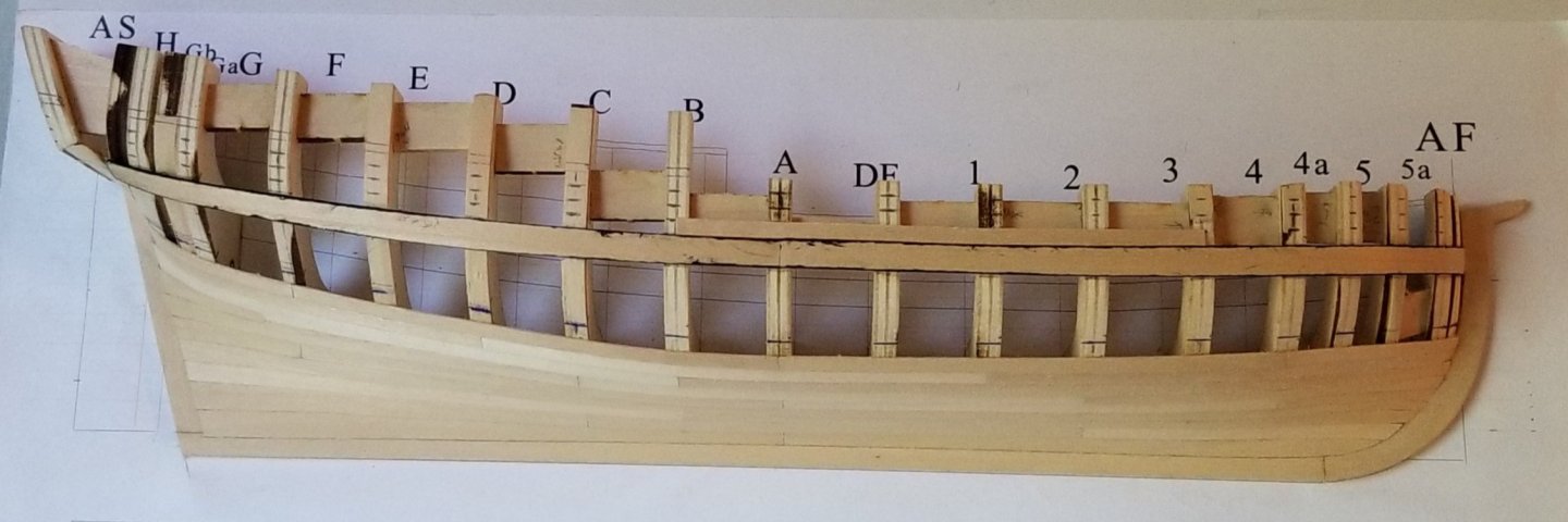
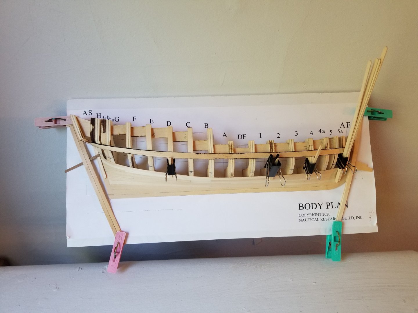
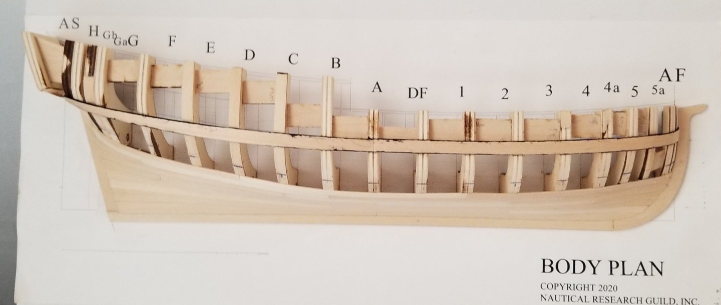
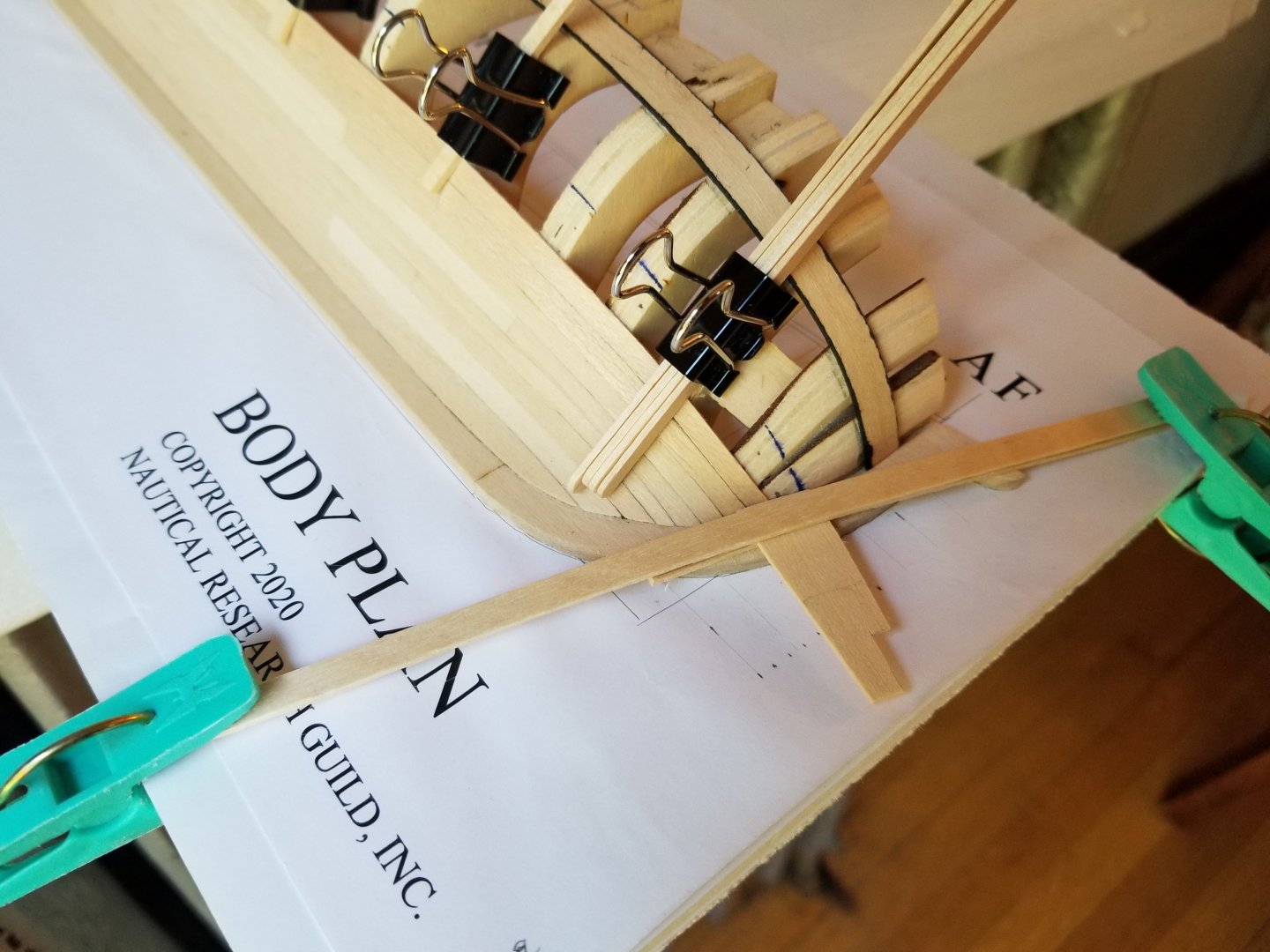
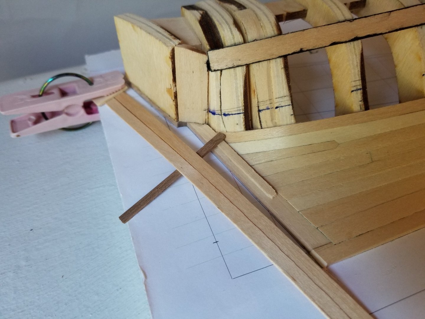
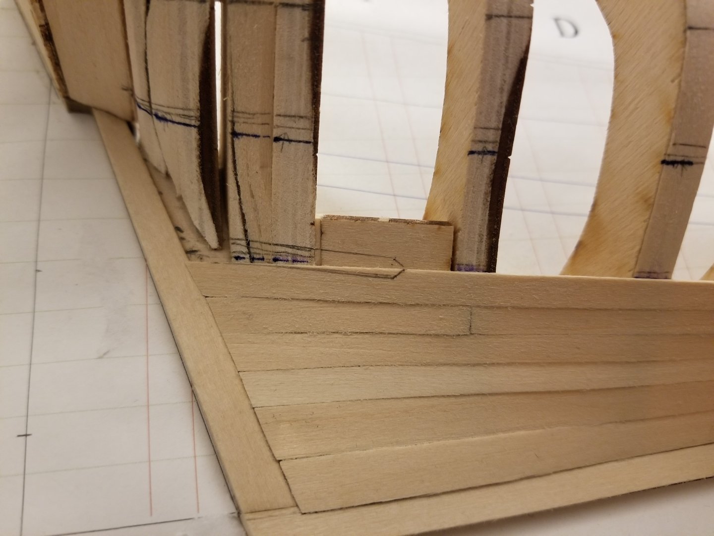
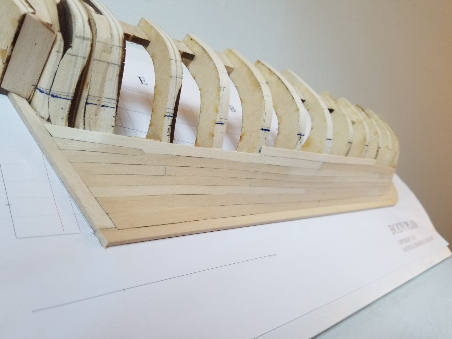
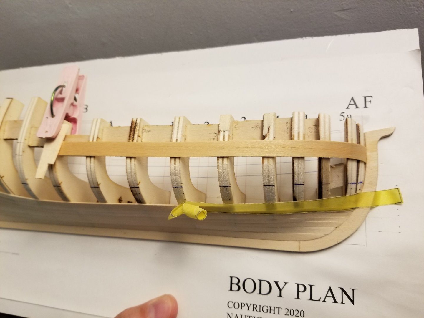
I've now finished the second band and the first strake above the wale. Although there are still challenges, I feel like my planking skills have improved over time and the run of each strake is getting better with each band. Now that the wale has been installed, it's becoming quite difficult to clamp the planks below it, as can be seen below. Thankfully I was able to slightly deepen the rabbet, allowing the bow planks to be much more firmly seated. The stern is also tricky, given that the planking now ends against the counter. The haphazard arrangement shown below doesn't work all that well, as the clamp only is in contact with the scrap blocks at the build board. I'm considering adding at least the first plank of the counter's planking in order to form at least a small rabbet of sorts, which would undoubtedly help at least a little to hold the tip of the planks in place. You can also see how the strake above the wale was left oversized at the end. Although I soon cut off the tip to bring it down to the transom, the plank is supposed to cover the ends of the counter planking. As can be seen, the wale also dips a bit, although I'm hoping the second layer of wale will cover this. In general, I'm not totally pleased with my counter and the end of the wale, which doesn't seem to have turned out quite like it should. This is an area where I feel the instruction manual could be clearer. That said, from the other build logs it looks like there's a lot of variation in this across builds, and they all look great, so perhaps it's not so much of a problem. As others have noted, the planks above the wale are very straightforward to shape. View from below: View from the stern: View from the bow: View from the side: I'm quite liking how the hull is coming together, even if I'm very unsure about how I'll clamp this last band.

- 82 replies
-
- 9
-
-
- half hull planking project
- half hull
- (and 2 more)
-
Very nicely done! The bevel on the planking is definitely confusing at first.
-
The build looks great!
-
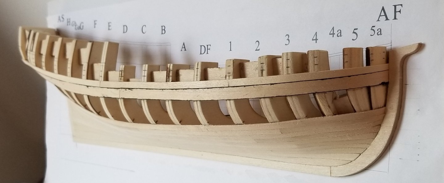
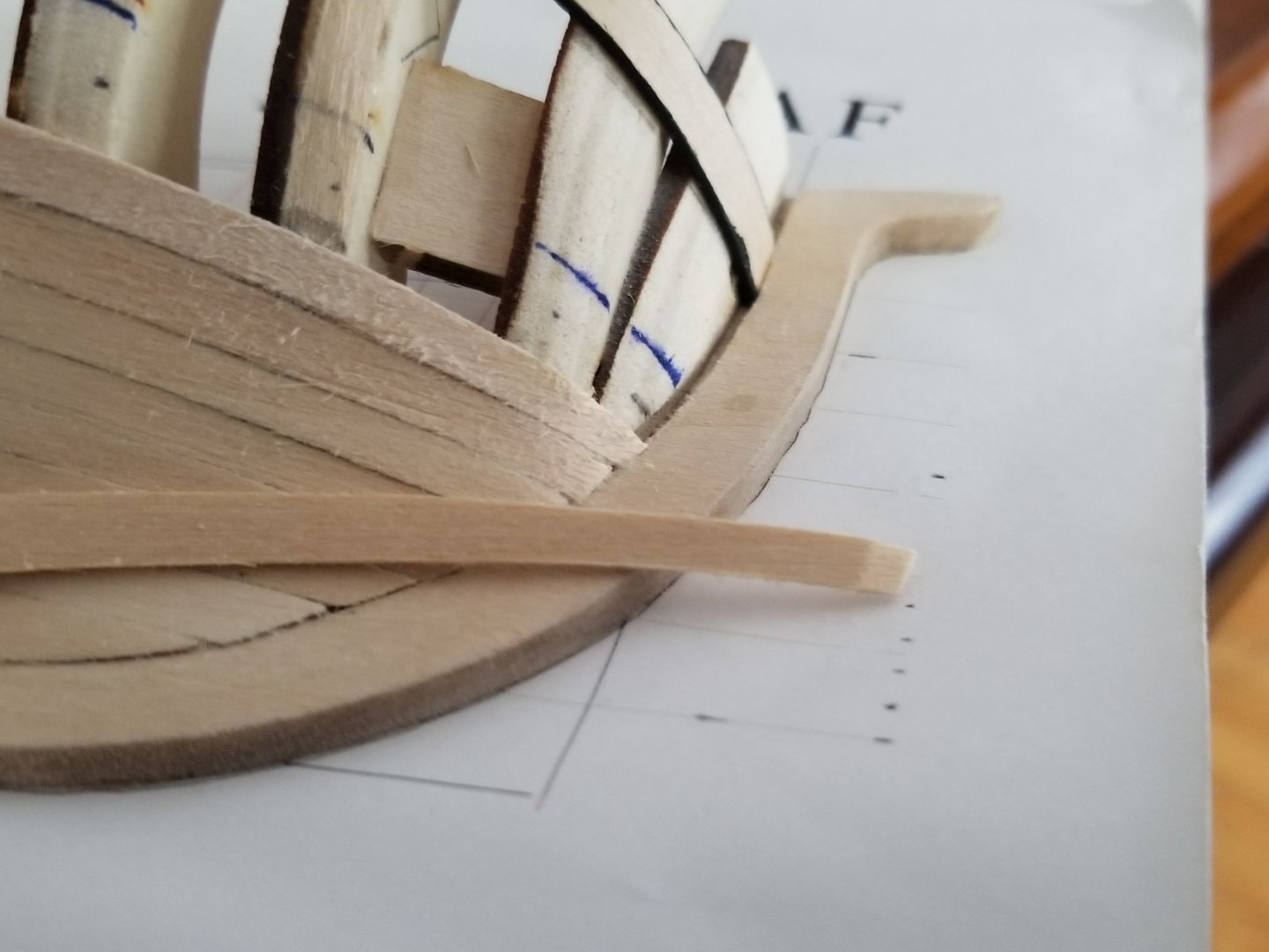
Thanks! With the wale in place, I've started planking above the wales while continuing to plank the bands below. First, I had to mark out the molding on the quarterdeck. I was then able to mark out the planking widths above the wale. I also finalized the fairing of the transom's bottom corner, which I hadn't done earlier because I wasn't sure where the wale would end up. By now, I've finished the third strake of the second belt, and started planking above the rail. So far I'm enjoying this build a lot, it's very fun to see the hull take shape. There are a few things I want to mention, though. First, I don't think I'll be doing a drop plank at the bow, as it looks like I have plenty of space to fit the full four planks there. I'm not sure what I did differently from the instructions, but I feel like a drop plank would lead to the planks in the last band becoming weirdly wide at the bow. Secondly, as the bow becomes quite bluff by this point of the hull, I've been having a lot of trouble test fitting planks to properly shape them. I'm not sure if I didn't properly fair it or what, but a few planks have snapped when I tried to test fit them around the bow, as can be seen below. (Thankfully it wasn't disastrous for that plank, as I was actually re-using an earlier plank I had accidentally cut a hair too short, so I was able to just trim off the broken end and continue.) What I've found works best is to get the plank approximately spiled, curve it to shape with hot water and clamps, and then finalize the shaping once it's properly curved and can easily fit around the bow. Third, I've also had some trouble fitting planks into the rabbet at the bow and stern. If I were to redo this build, I would make them a little deeper so there was more to seat the planks.


- 82 replies
-
- 7
-
-
- half hull planking project
- half hull
- (and 2 more)
-
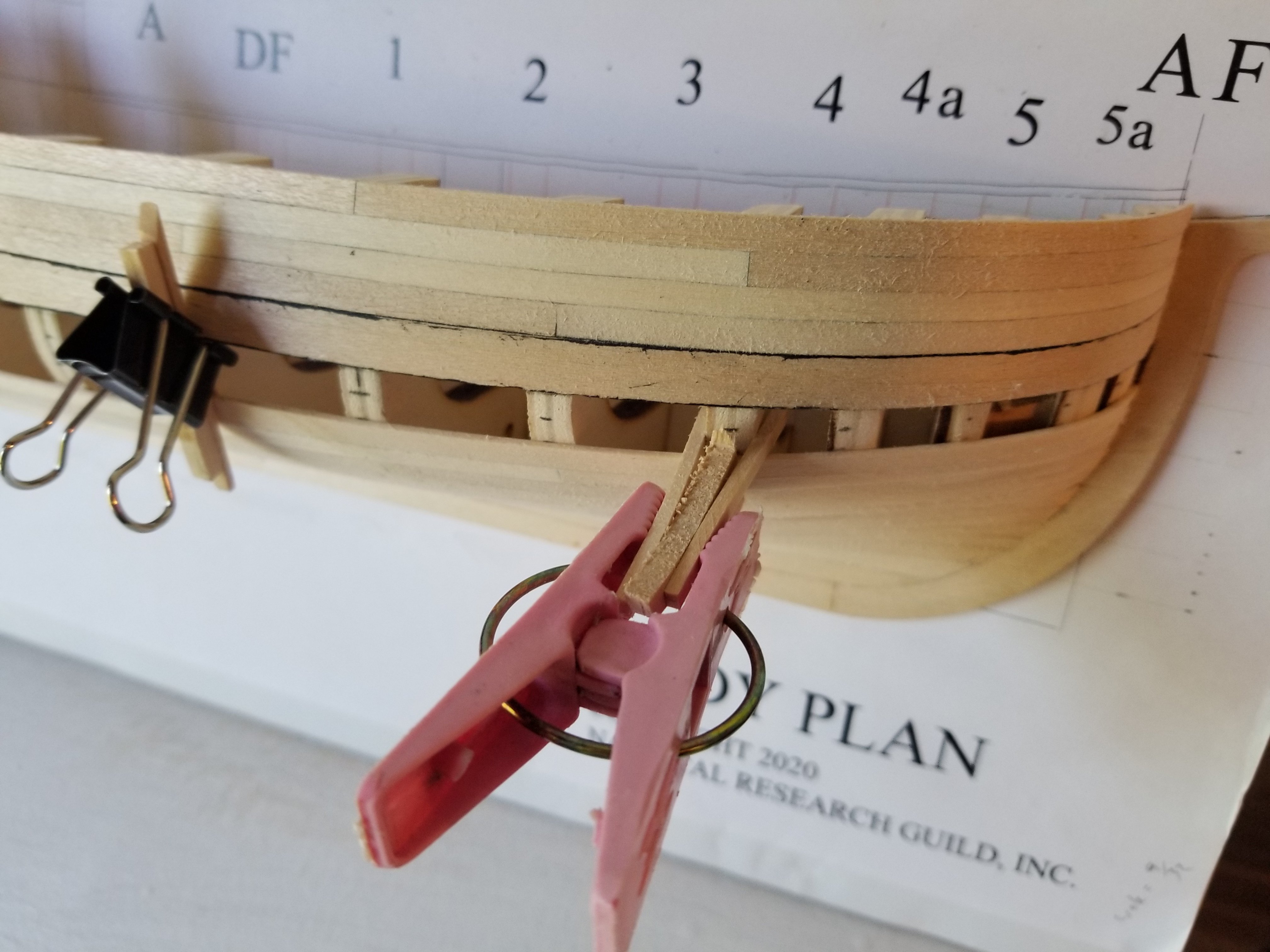
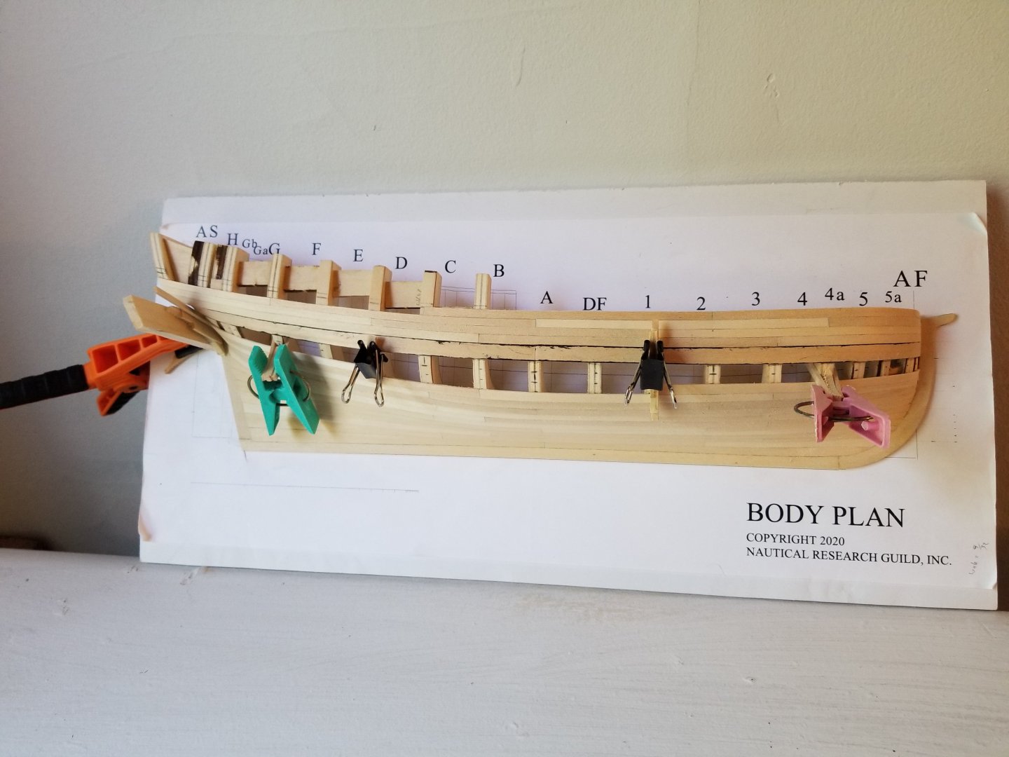
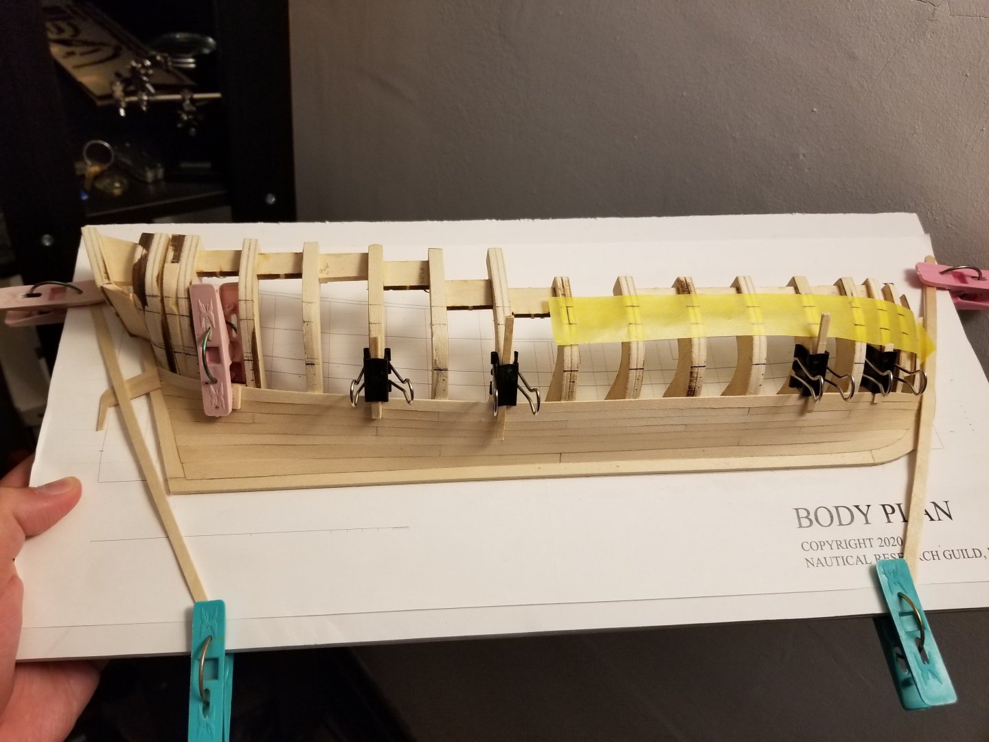
I'm continuing to make progress. The wales are now in place (or at least the first layer) and I'm midway through the second belt. As can be seen, creative clamping is a must. Further details of how I'm clamping at the bow: And at the stern: Unfortunately, with all the clamping material in the way, I didn't see until afterward that the bow plank somehow got weirdly twisted at the tip: I found that it wasn't quite as bad as it seemed, though. There isn't actually much of a gap between the plank and the plank below it, it's more that the plank below it is standing slightly proud of the rabbet. Preliminary sanding helped a lot. I also used an exacto blade to carefully trim the top of the plank to get rid of the odd upward twist. It now looks more acceptable: Meanwhile, I'm nearly up to the counter at the stern: Overall, I'm pleased with how the planking is coming along. I can certainly see areas for improvement in future builds, though.


- 82 replies
-
- 7
-
-
- half hull planking project
- half hull
- (and 2 more)
-
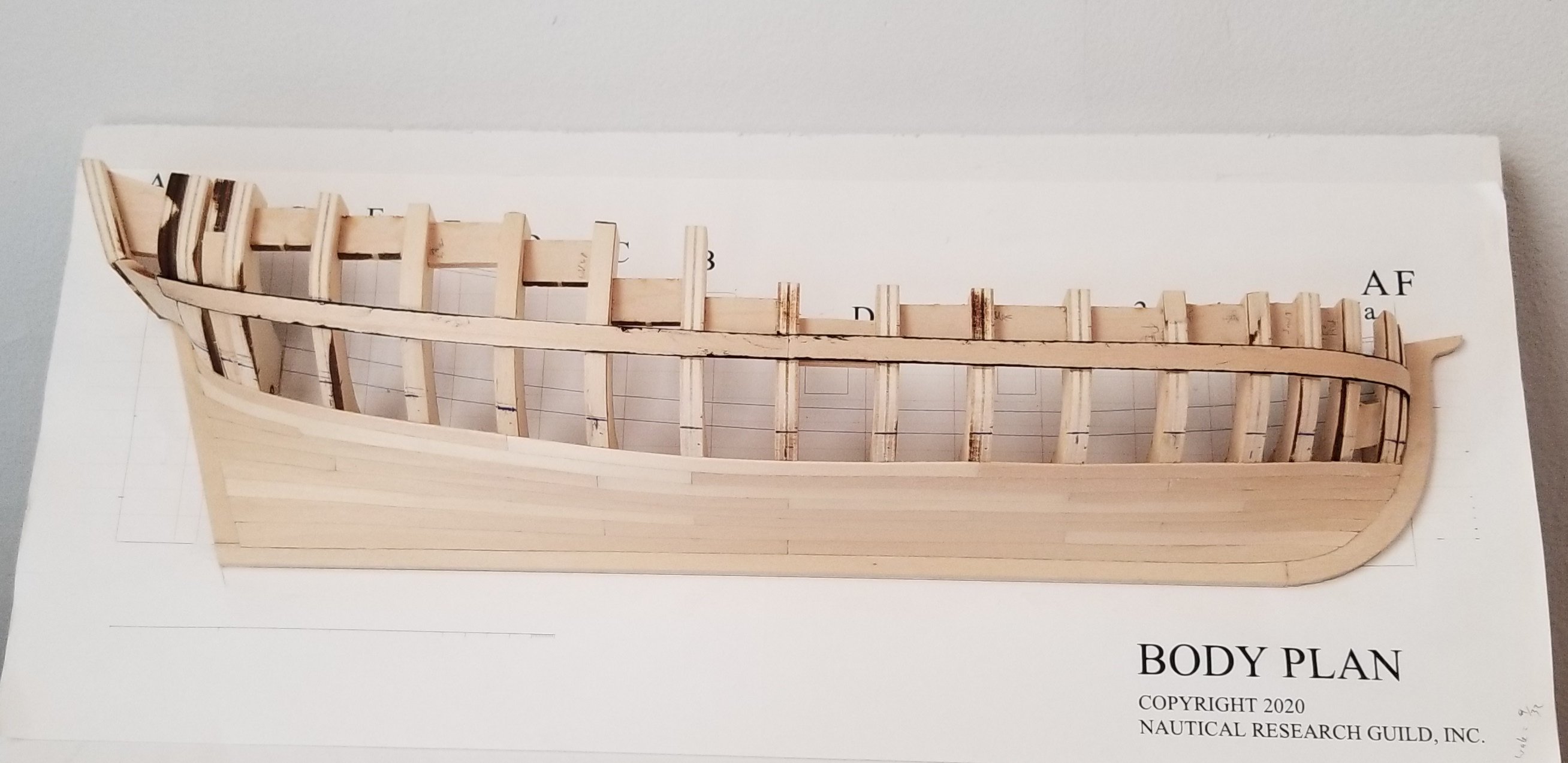
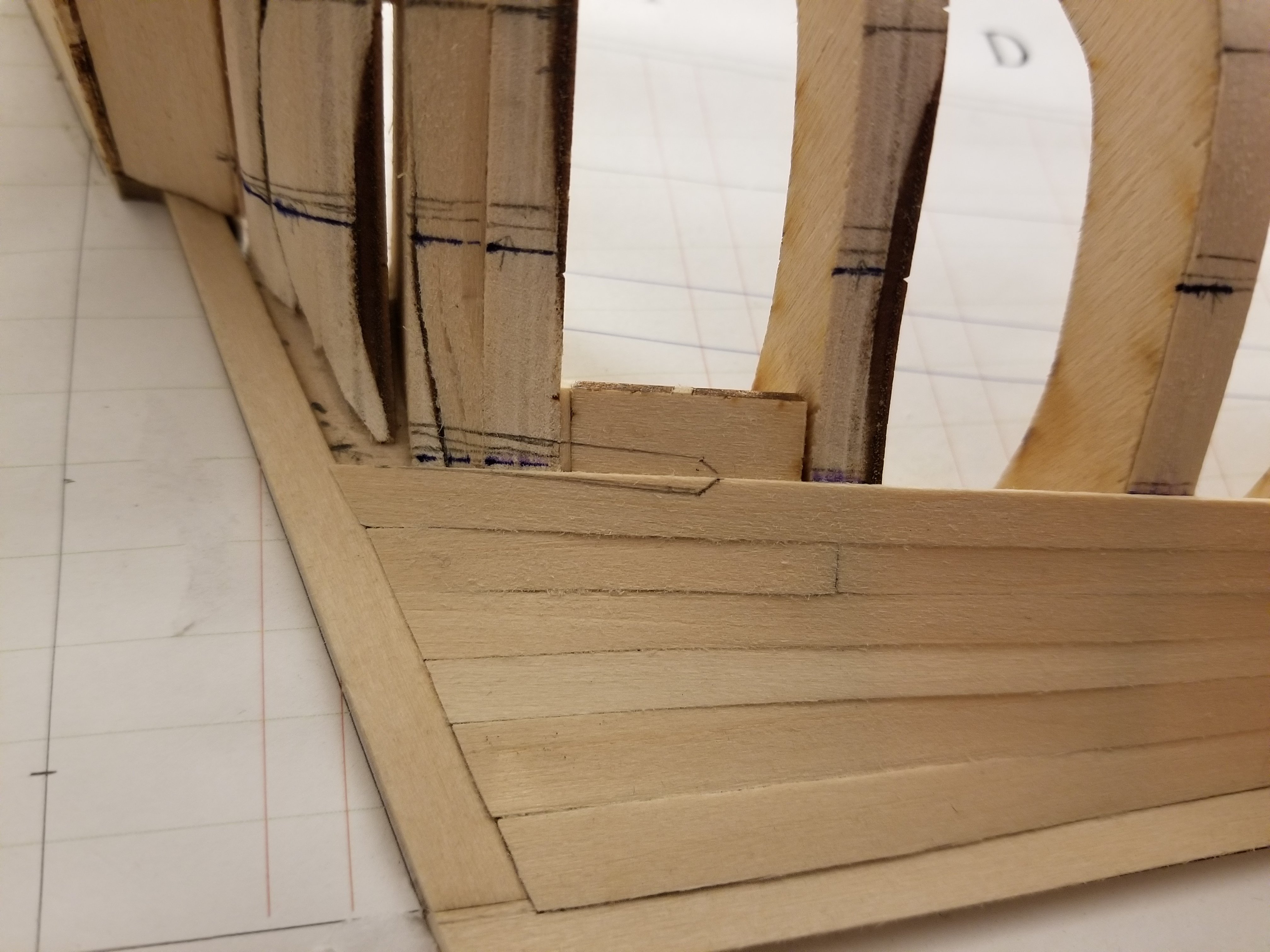
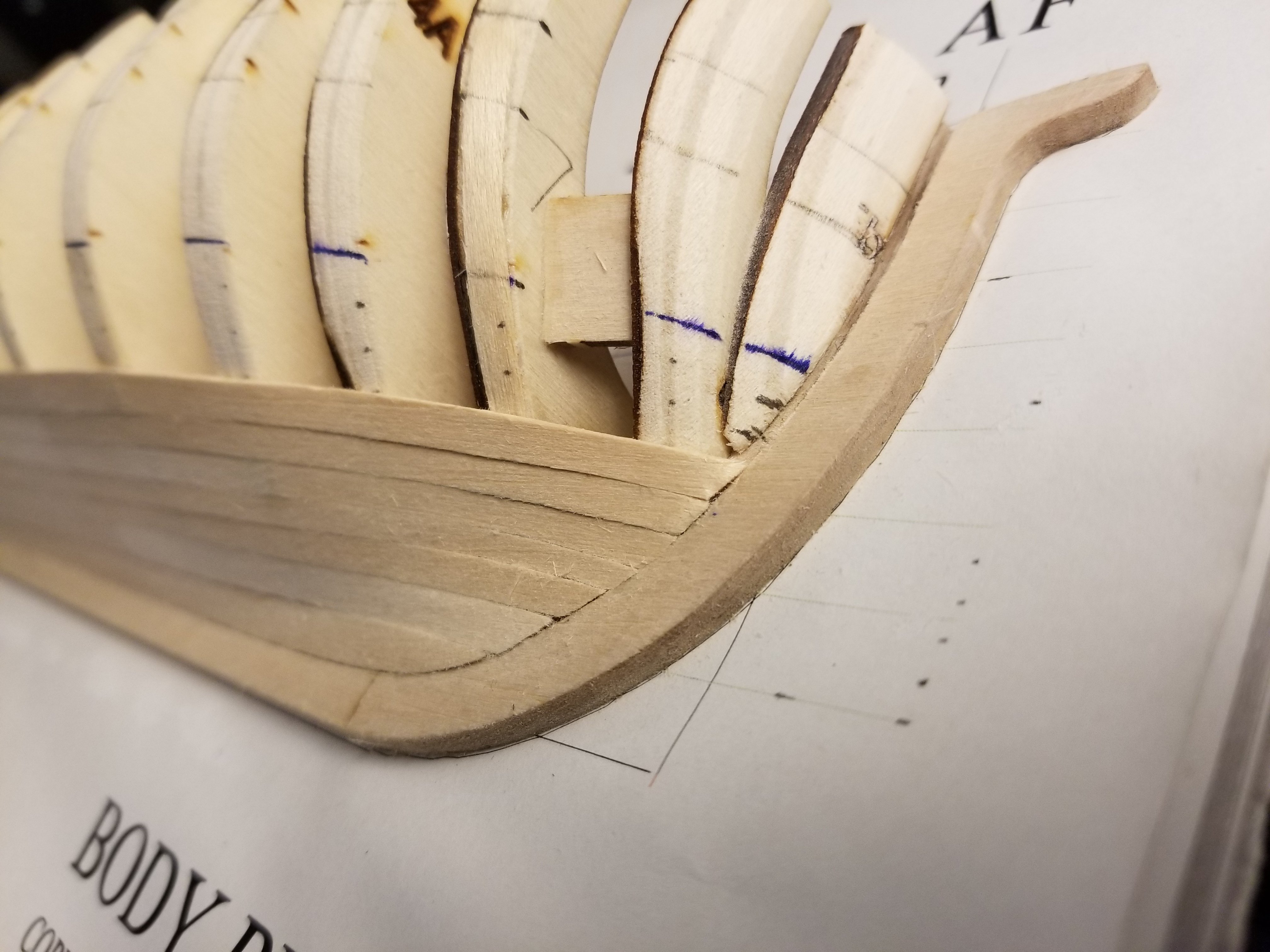
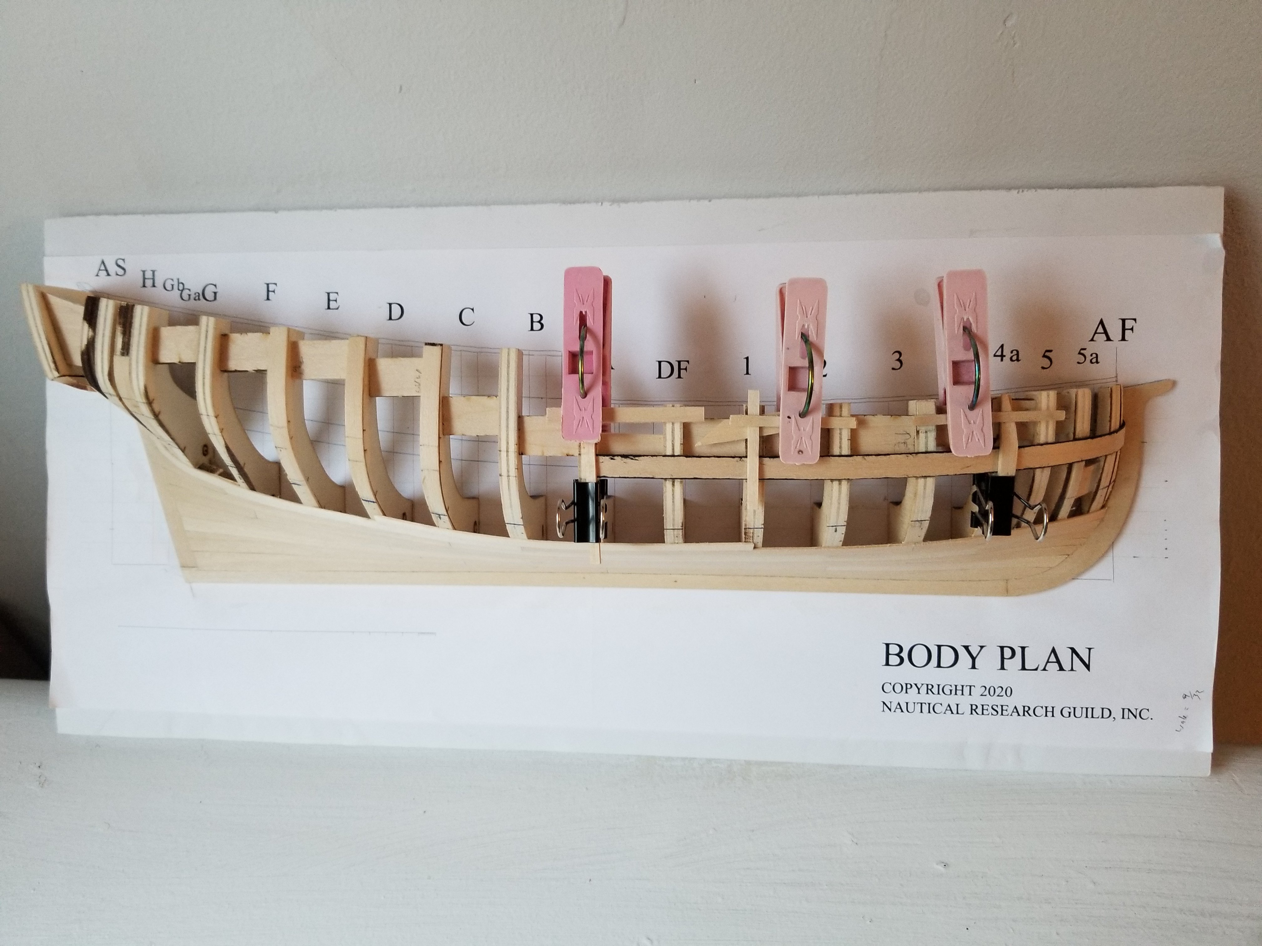
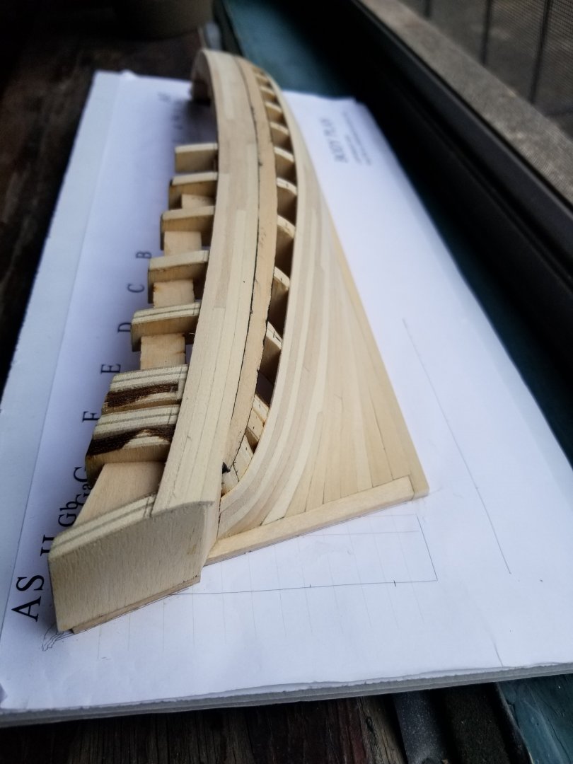
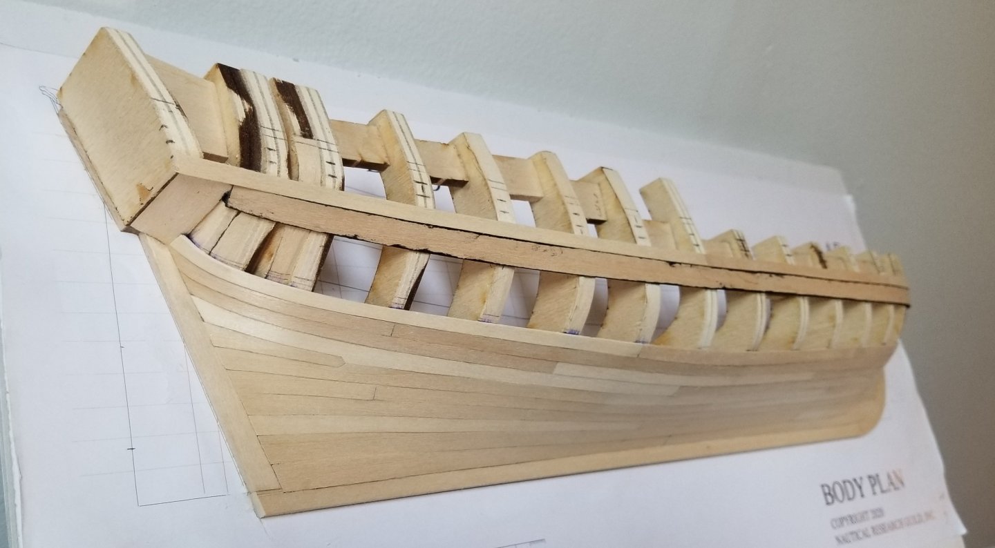
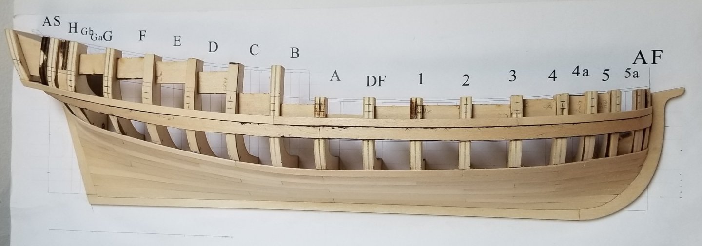
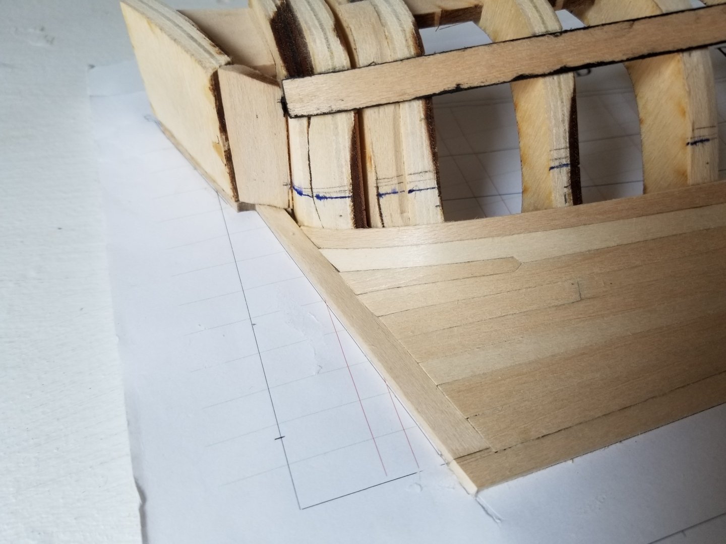
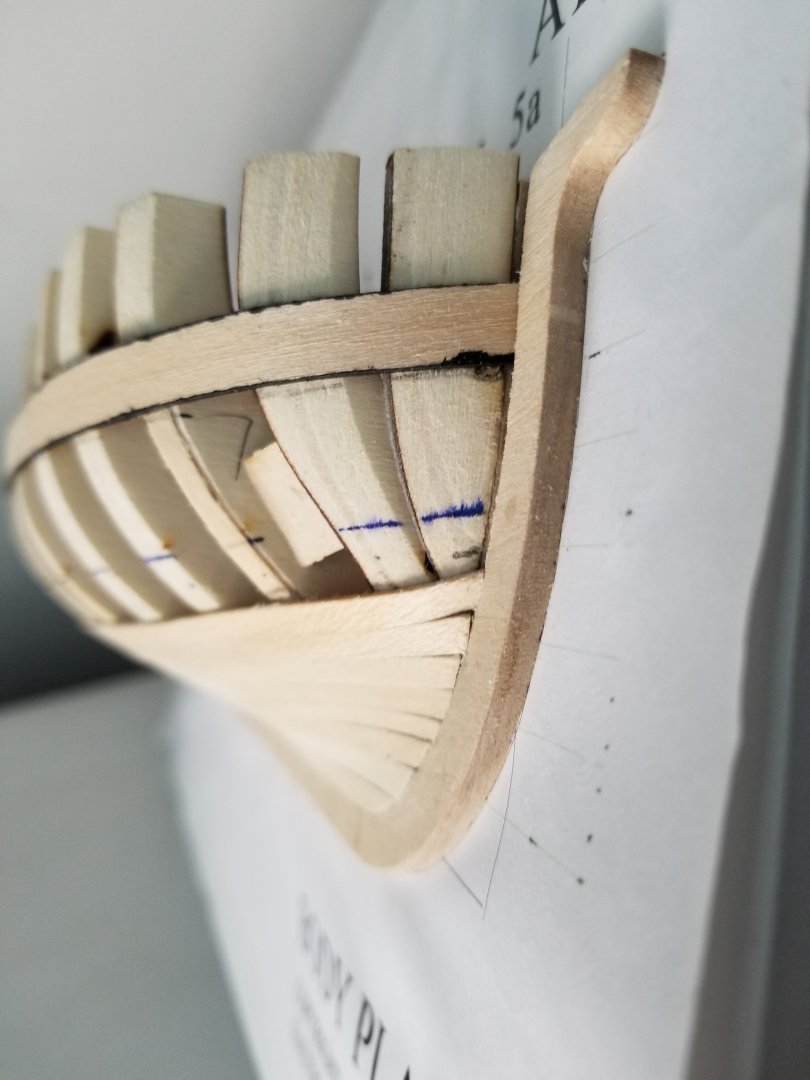
It's been a little while since my last post. I'd like to finish this before my move in late August, as the model will be much easier to pack if it's fully built and can be removed from the build board (or if the board can be trimmed substantially). It took some thought to figure out how to do the stealer at the stern. After considering different options, I decided to follow the example given in the instructions, rather than the other style of stealer shown in Toni's build log. First I marked it out on the hull. And then cut it to shape. It fit fairly well into the slot. I then began adding the next strake. I also decided that I may as well add the wale now, so I began marking that out. One issue I've been having is that it's been very hard to fit planks into the rabbet. I'm not sure if I didn't cut it deep enough. As can be seen, the bow plank ended up too short. Fortunately, it came off easily enough with rubbing alcohol. While I was redoing that plank, I also began cutting the first layer of the wale to shape. Fitting it was a little tricky due to the pronounced curve of the bow, which made it difficult to test fit. I ended up cutting the strip a bit oversize at first to bend it into shape, as seen below, so as to then do the final shaping afterward. I've continued working and moved on to the next strake. As can be seen, the color variation between sheets of basswood has ended up nicely highlighting the stealer. From this angle, you can also see another issue. Following the instructions, the stealer ends on a bit of backing that was placed between frames. Unfortunately, clamping the hull to that backing has led to a bit of a flat spot in the hull in that area. I'll have to see if sanding the hull helps, but I'm not sure it will. I'm also not sure if this could have been avoided--the only way I can think of would have been to add the backing piece much earlier in the build and fair it in place such that it followed the curve of the hull. In any case, this is a minor issue and I can live with it. In any case, I painted the edges of the wales black, and have begun gluing them in place starting at the bow. As can be seen, I had to be a bit creative with the clamping. Sone of the frames are too thick for me to fit the clothespins around, so I had to use several bits of scrap wood to instead clamp to the spacers between frames.


- 82 replies
-
- 6
-
-
- half hull planking project
- half hull
- (and 2 more)
-
Yes, it's definitely very interesting to ask why certain topics get researched and others don't. In this case, I suspect it's mostly a general lack of study of workboats in Mexico, with anthropology's focus on indigenous societies leading to some studies of dugouts. The lack of study of colonial workboats is a bit odd, though, as other aspects of colonial-era material culture have been very well-studied and have received a lot of attention. In any case, as part of my upcoming move back to Mexico, the Canoa has been packed and sent off, arriving safely. I'll get back to work on it in September.
-
I'm looking forward to following your build! On the crooked transom: if you're using white glue, it comes off very easily with a bit of rubbing alcohol and can be re-glued once it dries.
-
Congratulations on finishing, what an amazing build! The figures really make it come to life, too.
-
Out of curiosity, are there any updates on this build? I know you've been very busy with the Speedwell, new blocks, and other items, so it makes perfect sense that it's on the backburner. But it's a very interesting build. These small workboats are fascinating and under-represented in kits, especially at the level of detail and accuracy you're going for. And this method of making the frames looks like an excellent way around the challenges of building many thin frames without doing a shell-first construction with frames added in afterward. Is there any chance the kit would be available someday in 1:32 scale?
- 16 replies
-
- 6
-
-
- Sophia Rose
- Block Island cowhorn
- (and 1 more)
-
Really fascinating stuff. I wonder if there are any oral histories of fishermen or boatbuilders during the war that might have an answer?
-
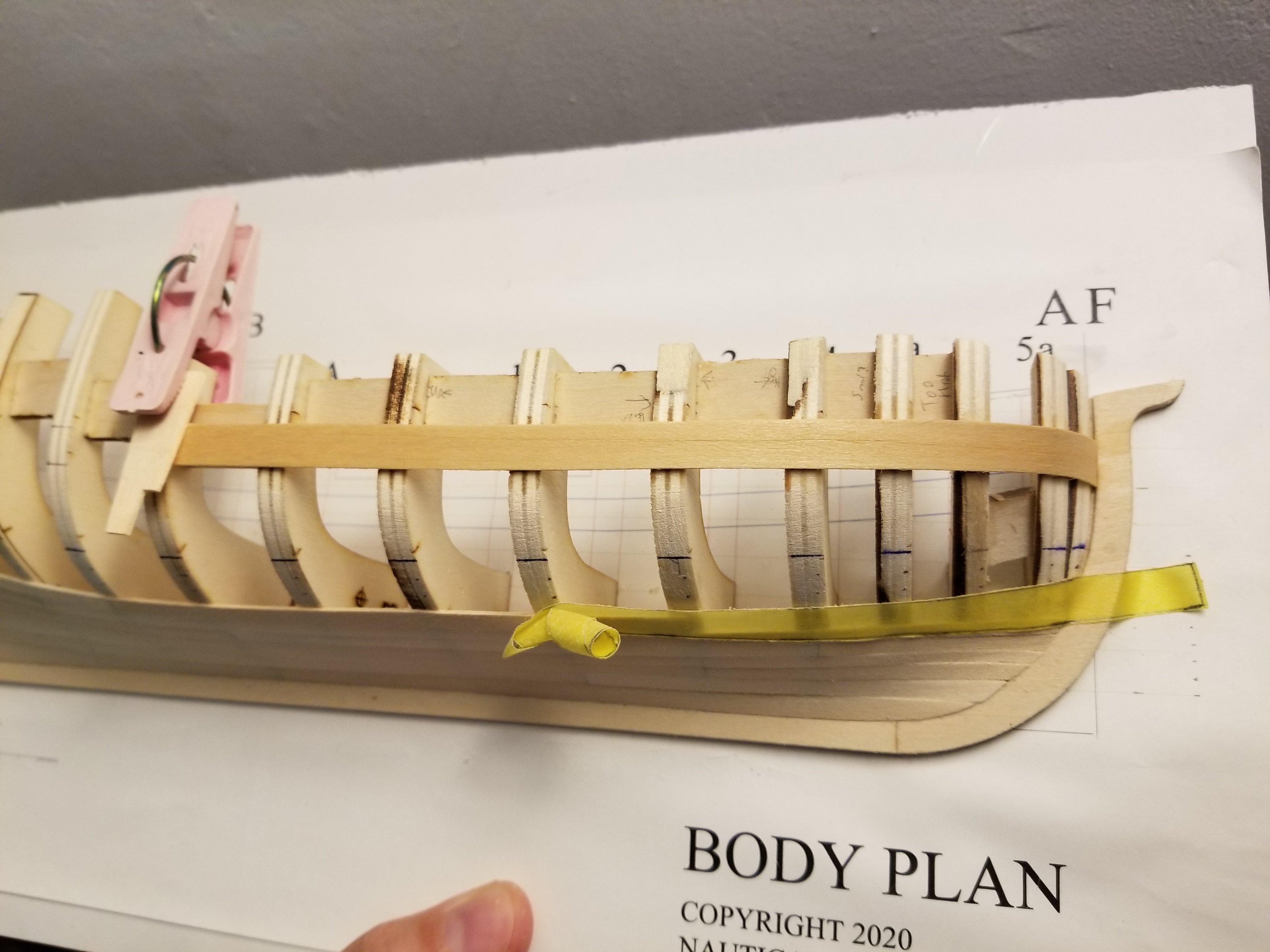
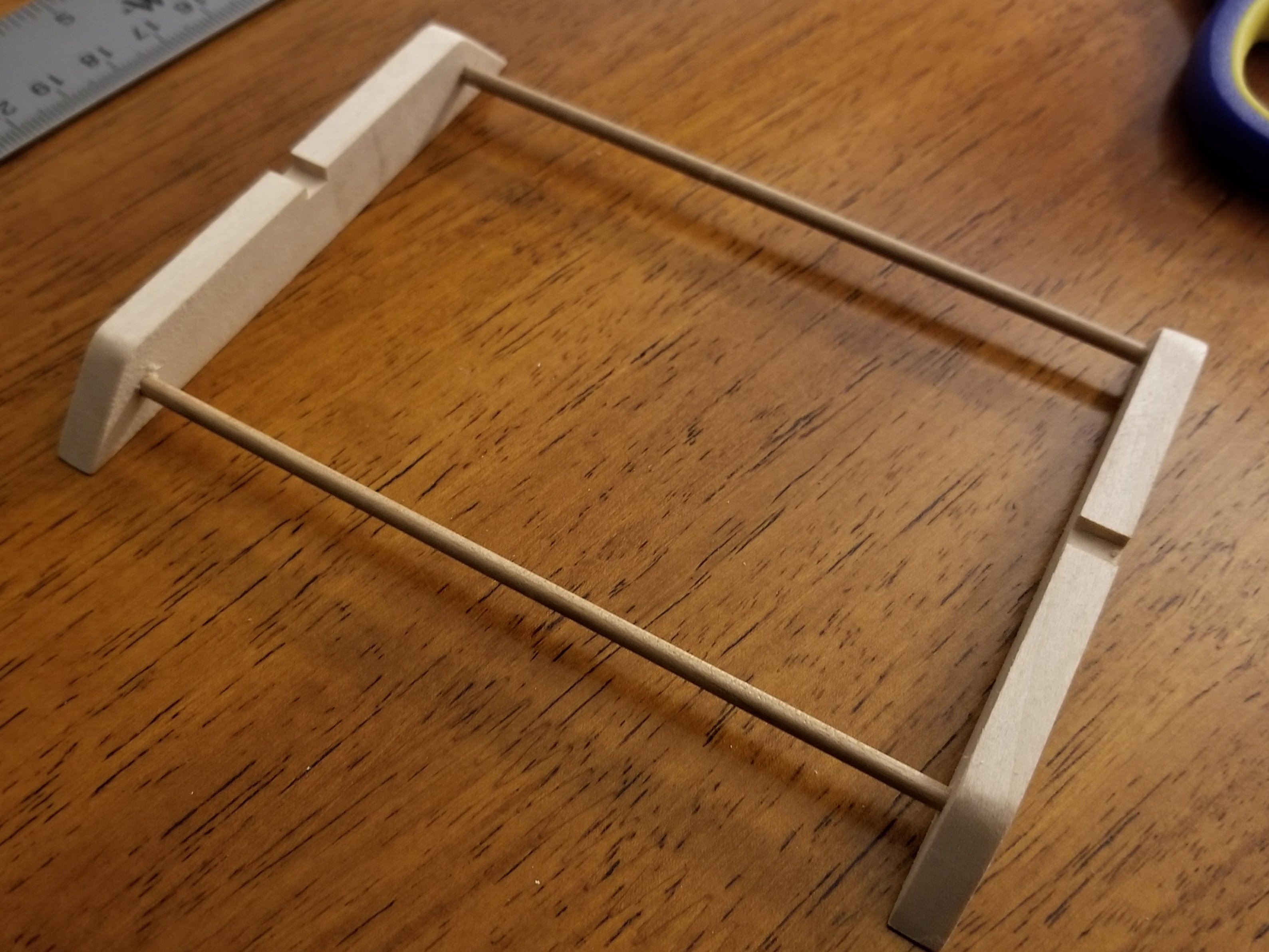
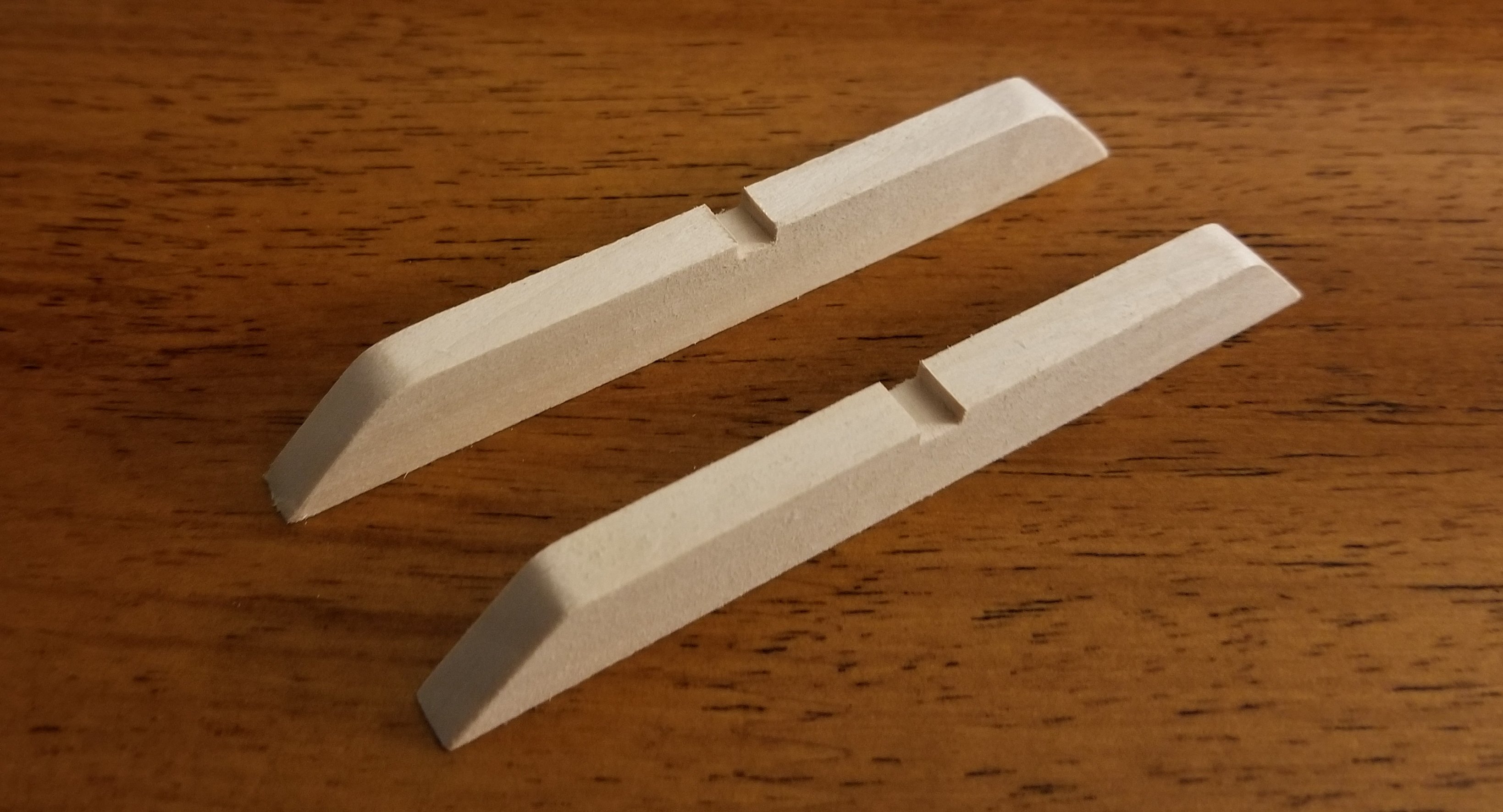
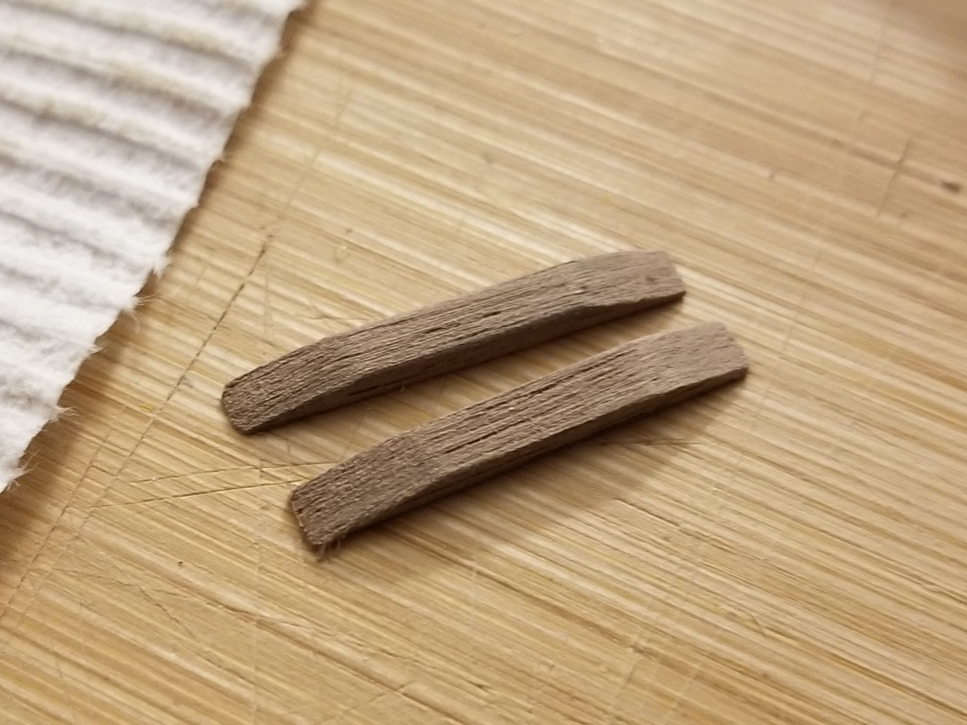
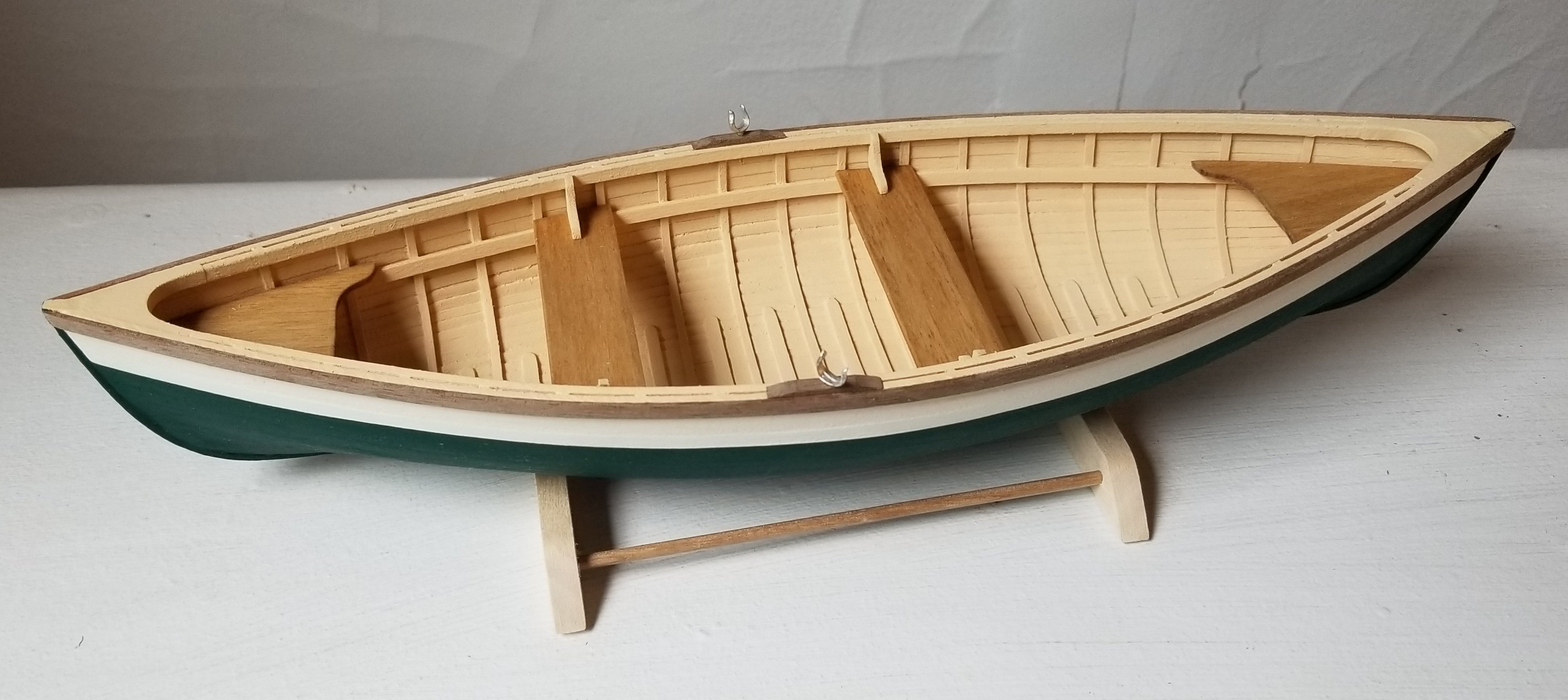
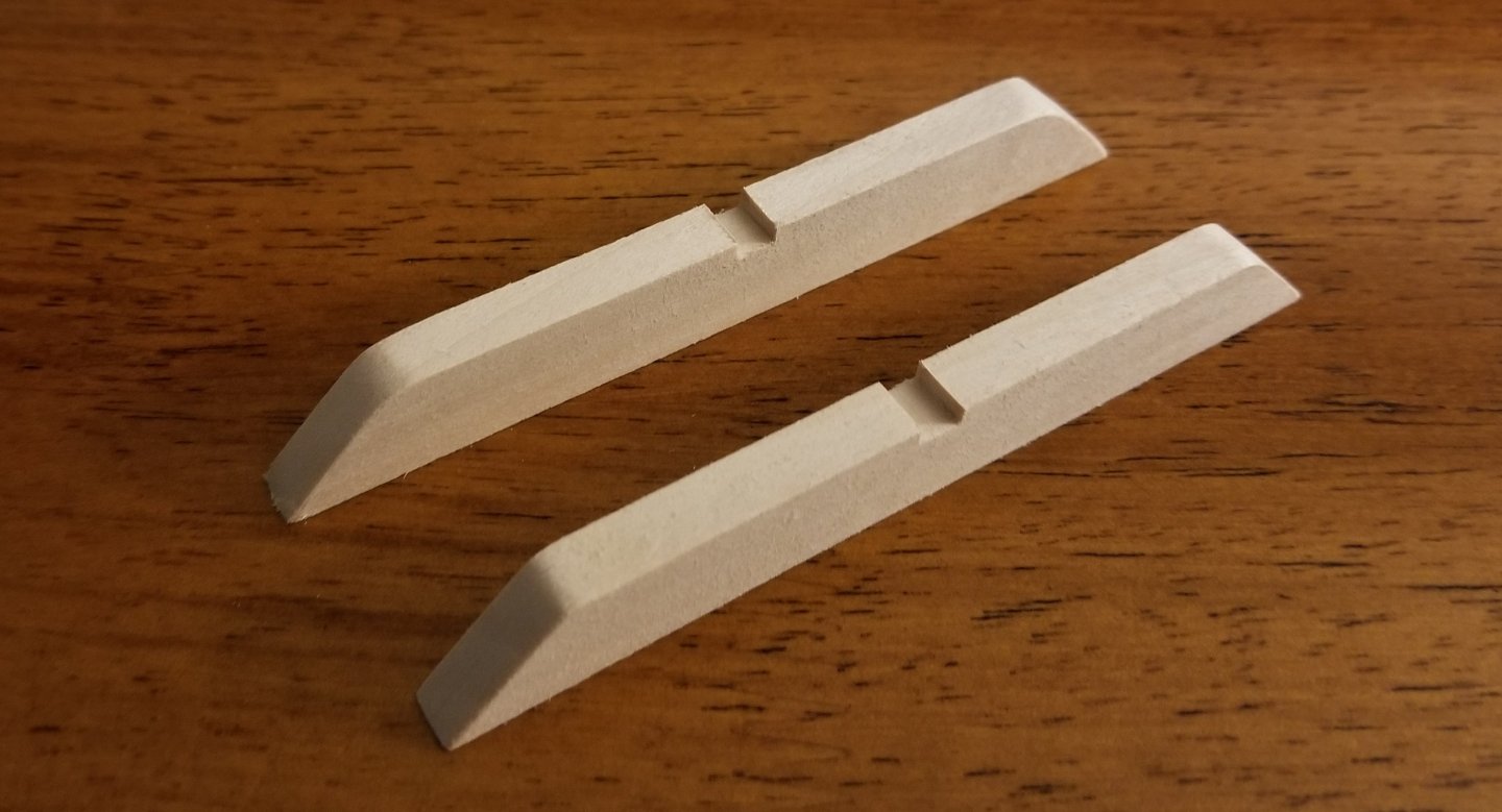
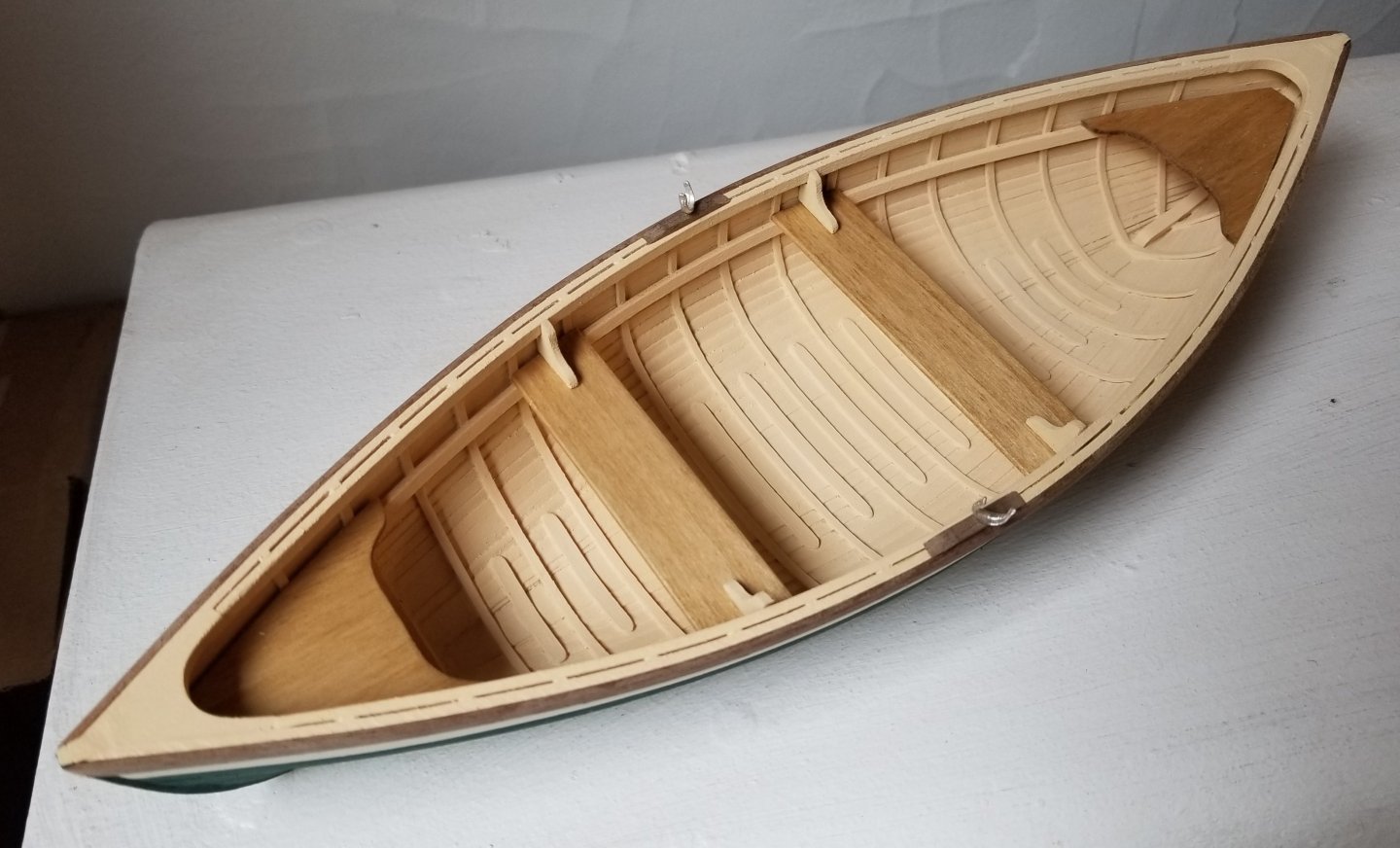
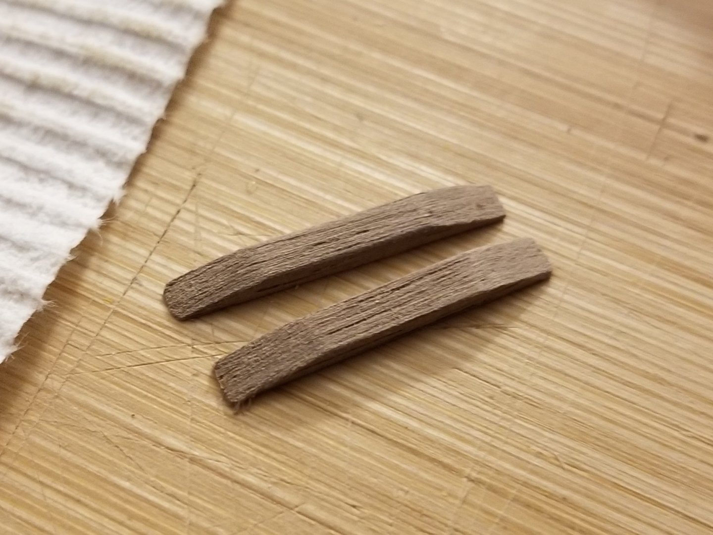
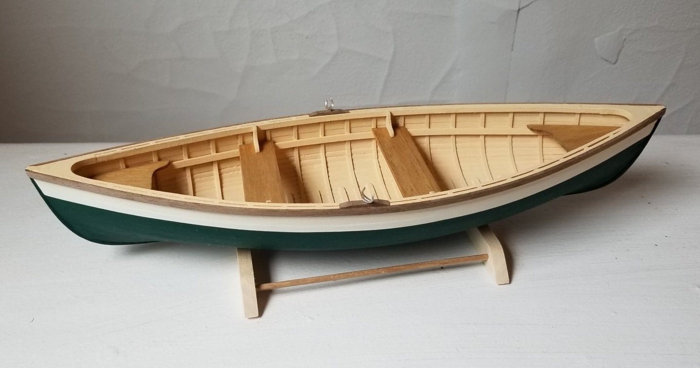
Thanks, all! I next made the oarlocks. While the instructions/inventory say the kit is supposed to include a piece of wood specifically for these parts, I couldn't find it, and instead used the leftover strip from the rub rail, which was the same size. I should note that, while I've been writing that these parts are walnut, the instructions actually say that they're mahogany! I'm not sure how I got it in my head that they're walnut. They look much grayer than the mahogany that I've seen and used in the past (like on the Juana y José), though, with a very different grain pattern, and also seem less reddish compared with photos of other build logs. So I'm not sure if they're actually mahogany or something else, or if the company changed the material. In any case, the oarlock blocks were not difficult to shape. I then attached them and drilled out the holes for the oarlocks themselves, which are cast in a silvery metal. I'm not sure whether to try painting them or blackening them, or if I should just leave them as-is--I don't think the silvery color looks bad. Next, I made a simple stand. I still have to decide whether to stain it, paint it, or leave it as-is. At this stage, the main things left to build are the accoutrements--oars, lobster trap, and other fishing gear. I have to say that this is quite an enjoyable kit.


- 65 replies
-
- 11
-

-
-
- Maine Peapod
- Midwest Products
- (and 1 more)