JacquesCousteau
-
Posts
1,362 -
Joined
-
Last visited
Content Type
Profiles
Forums
Gallery
Events
Everything posted by JacquesCousteau
-
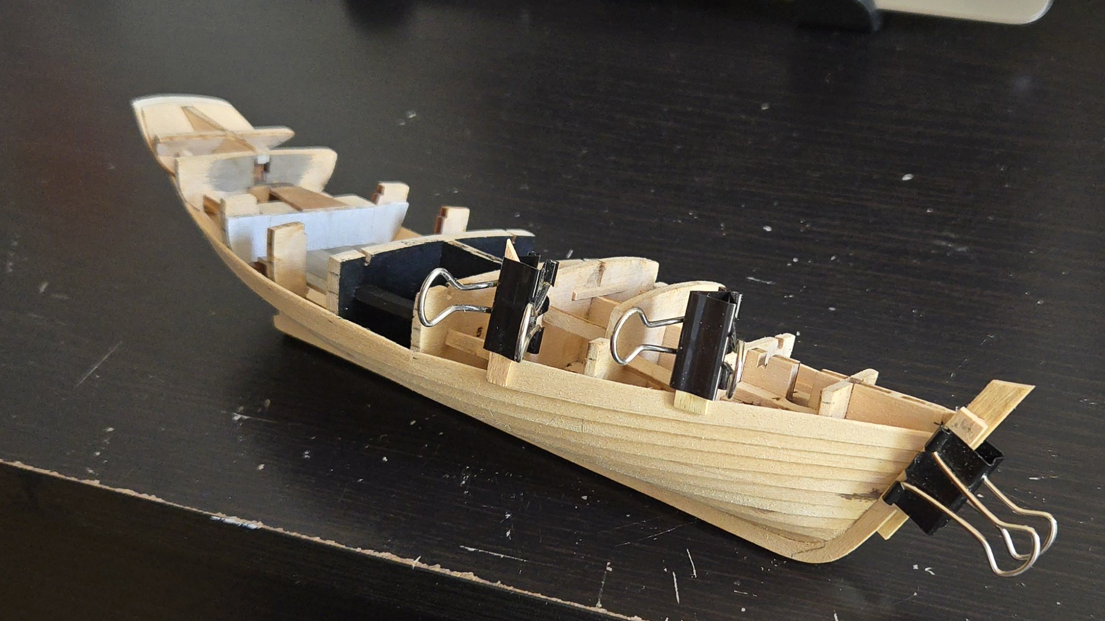
 Thanks, @Stubby, I enjoy research about as much as building! And thanks, @Keith Black, for the pump examples! More work on planking. I've been able to get a little better at lining up the top line of the plank joints. One issue I've had is that, due to the different plank widths and strake lines of my model compared to the kit design, I haven't been able to use much of the kit-designed prespiled planks. It feels like a real waste--it's a great feature of the kit, but it doesn't really work if you go with lapstrake planking. So I was happy that, for the next strake, which is the one below the sheer strake, I realized that I could make it from the kit-supplied sheer strake, which for whatever reason was slightly too short to work as the sheer strake on mine. (Maybe my transom extends a little farther aft than it should? Or I screwed up something in the scan and laser cut process?) It's a lot wider than the normal planks, so I could spile from it, as seen below. At this point, there's very little bulkhead to clamp to, so I've had to be a bit creative with rubber bands. I now just have the sheer strake left to add. I feel like, for a vessel of this size, it would probably be best to make it from a single piece, although I'm not looking forward to the complex gluing process that will entail. I'm pleased with the lapstrake planking so far. Before painting, I think I'll add a coat of shellac to help seal and strengthen the wood so I can touch up any stringy/ragged visible edges. Elsewhere, I've begun work on the rudder and mast. The mast is made from two layers of basswood, which mitigates against the relative weakness of basswood as a mast. Before I round off the mast, I need to decide whether it should be round all the way through, or squared-off at the deck. My initial thought was that, on an unstayed mast, a square cross section low down would keep it from spinning around. I began cutting the mast step partners square, but accidentally made them bigger than they should be, so it doesn't quite fit like it should and I'll need to take care when I step the mast. Moreover, it looks like Chapelle's plan shows a round mast at the deck, so maybe I should just round it all. I'm also trying to figure out whether to use brass rod or wood for the rudder shaft.


-
Very cool project, looking forward to following along!
-
Very nice work!
-
The issue is also discussed in Bryan Woods' build log:
- 21 replies
-
- 2
-

-
- Lowell Grand Banks Dory
- Model Shipways
- (and 1 more)
-
I couldn't remember how I did it on mine, so went looking. I don't discuss it in my build log, but there's a photo in the post linked below showing what looks like your second/middle option.
- 21 replies
-
- 2
-
-
- Lowell Grand Banks Dory
- Model Shipways
- (and 1 more)
-
Looking forward to following along! I'm curious to see how the birch plywood is. Your understanding of the beveled planks is correct.
- 21 replies
-
- 3
-
-

-
- Lowell Grand Banks Dory
- Model Shipways
- (and 1 more)
-
Very nice work!
-
This post is about paper modeling rather than wood, but it may be helpful. Basically, to figure out the bulkhead shapes, you need to take the forms given in the section drawing and mirror them (as the section drawing shows the aft half of the hull at left and the fore half at right). For the central spine, the bulkhead slots would be located at the section lines (the vertical lines running through the side view). The spine would look more or less like the side view, but it would only extend up as far as the lowest deck you're modeling, and you'd have to decide whether it will include the keel/stem/sternpost or if that will be added separately. The NRG has a useful drawing on interpreting lines drawings that may be helpful: https://thenrg.org/articles/interpreting-line-drawings I'd recommend checking out scratch build logs to get a sense of the process.
-
Thanks, @wefalck, @Paul Le Wol, and @Kenchington for sharing your insights! I think I will go with a very simple pump handle, as even the stowed lever looks like it takes up too much space for a small cockpit. As for the pump design, it seems like I have several plausible options, so I'll have to think some more about what would look best and be feasible to model. Thanks again! If you had asked me three years ago for my thoughts on late-nineteenth century workboat bilge pump design, I would have looked at you like a crazy person. Now I feel like I'm starting to learn enough to actually have some thoughts on the topic (although there's still a lot more that could be learned).
-
Welcome! Very nice work on the Beagle (despite the kit's issues). I hope you'll do a build log for your next model!
-
Nice work and good repair!
-
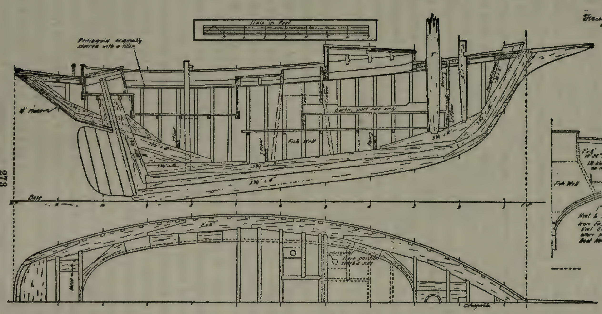
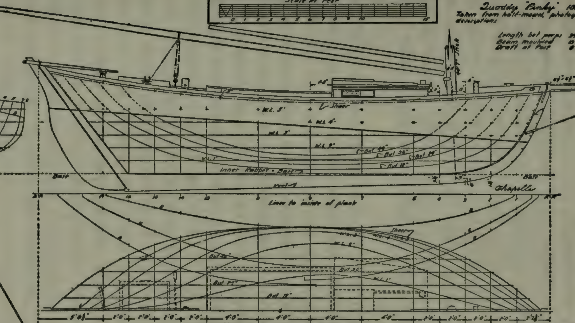
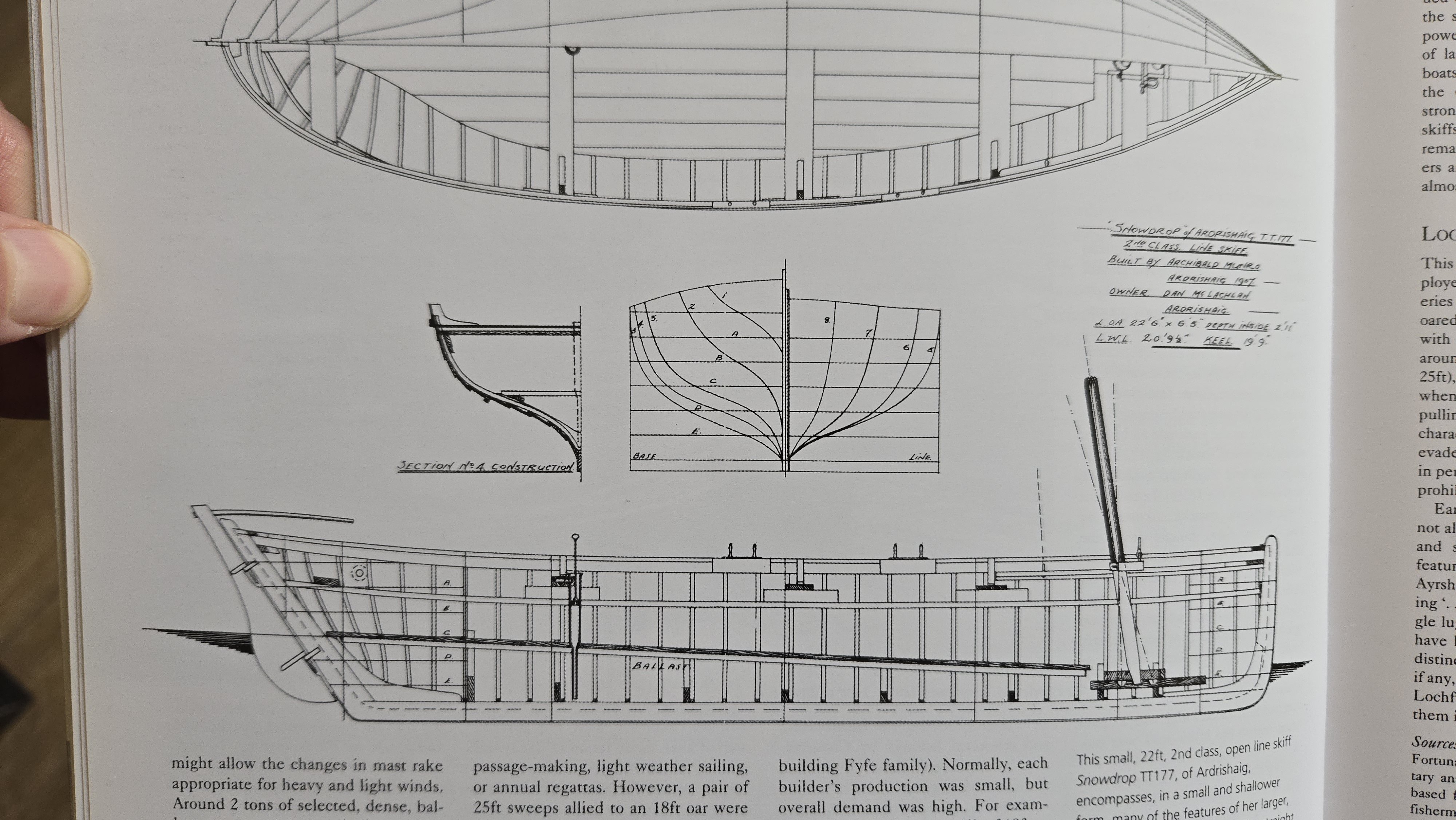
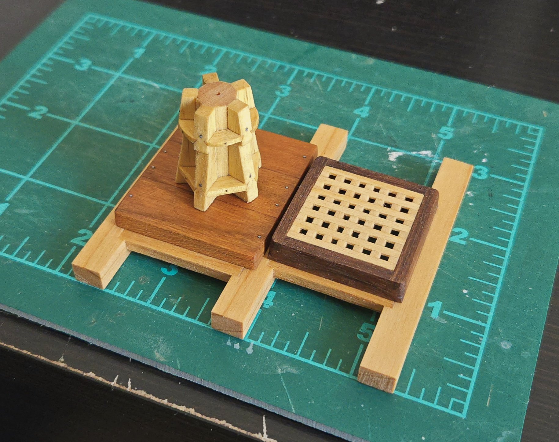
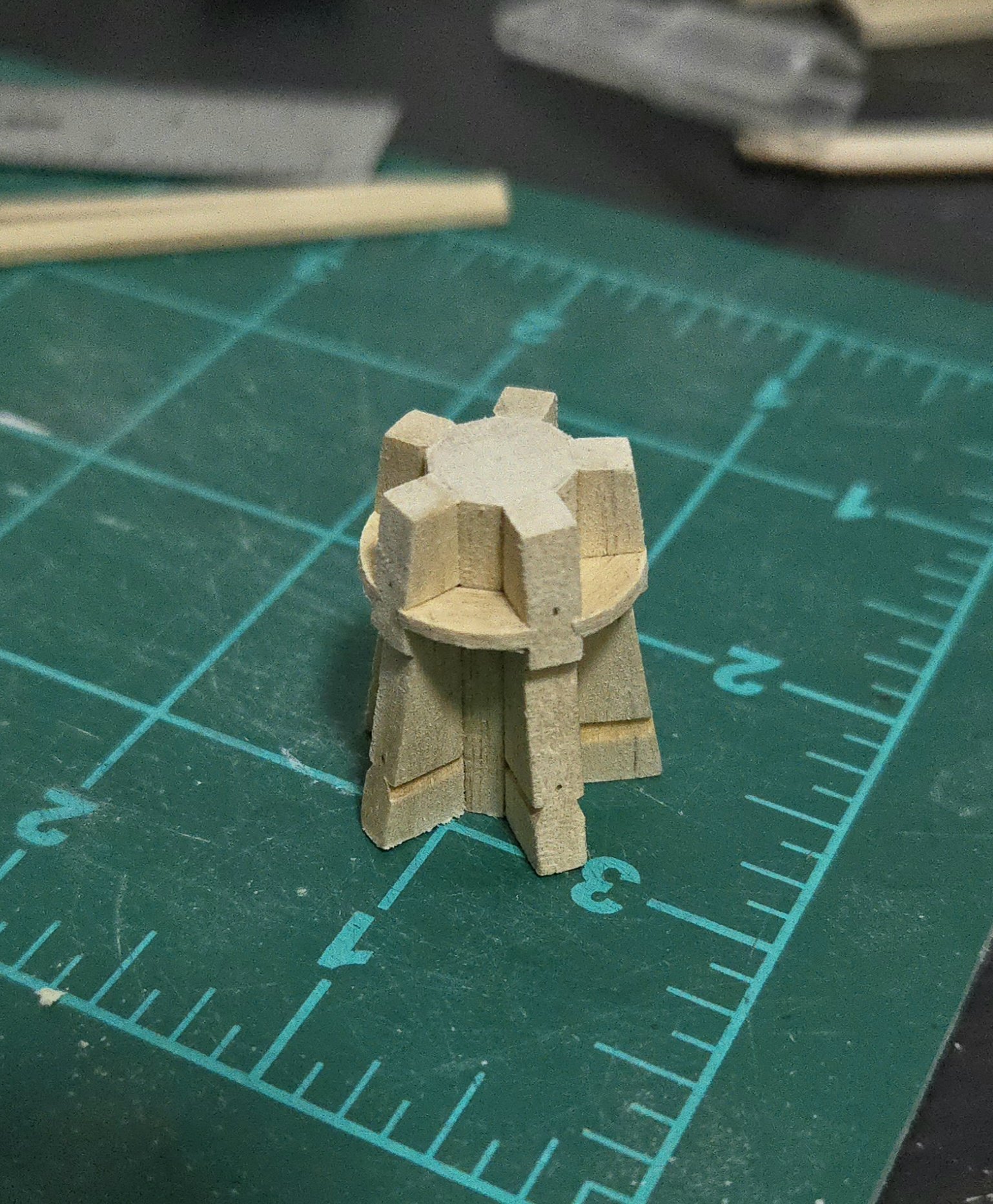
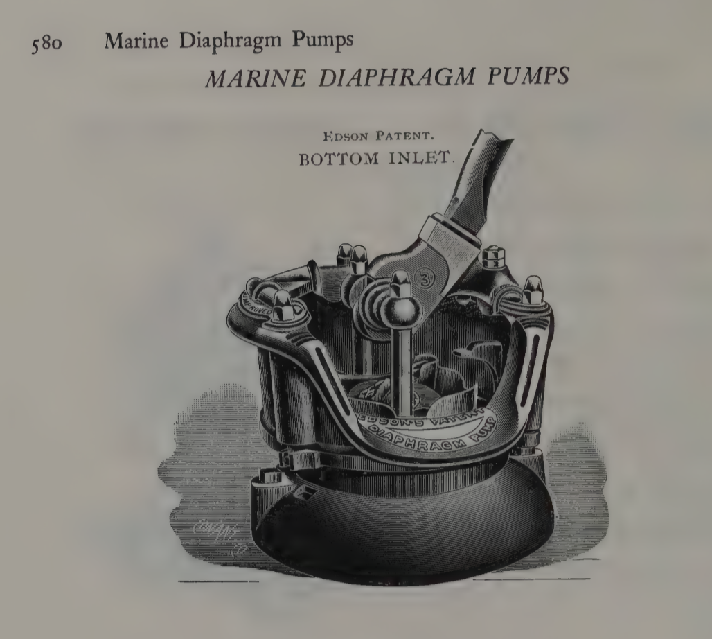
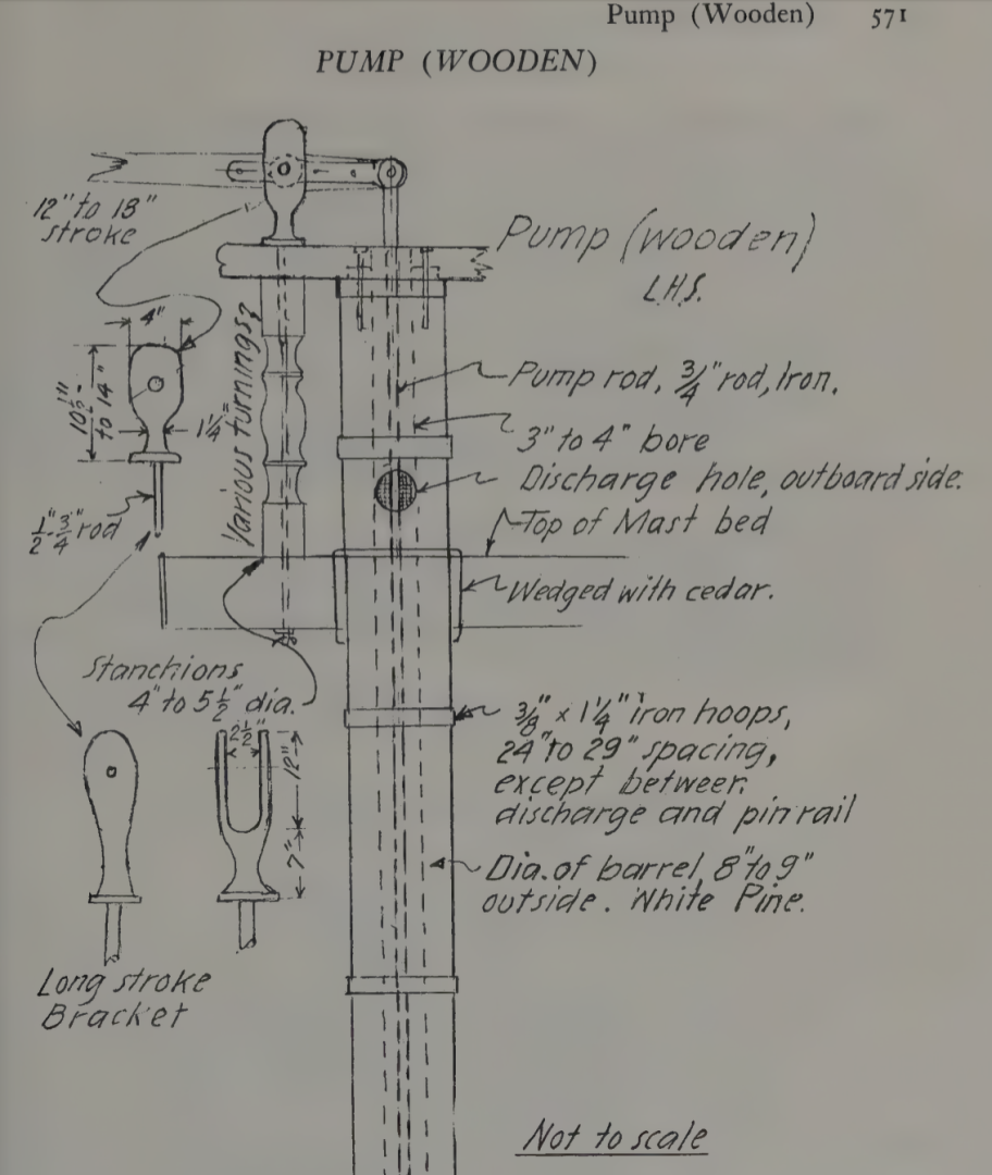
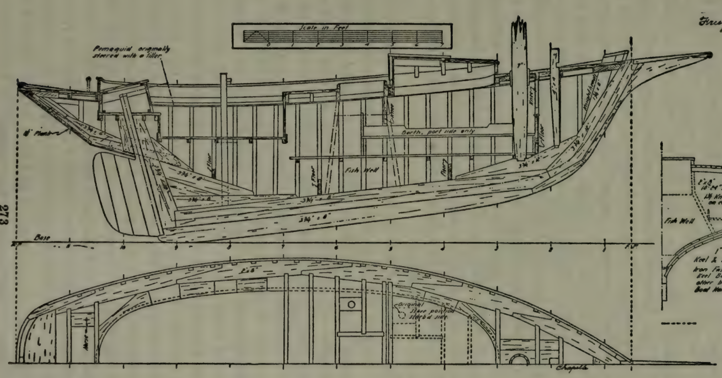
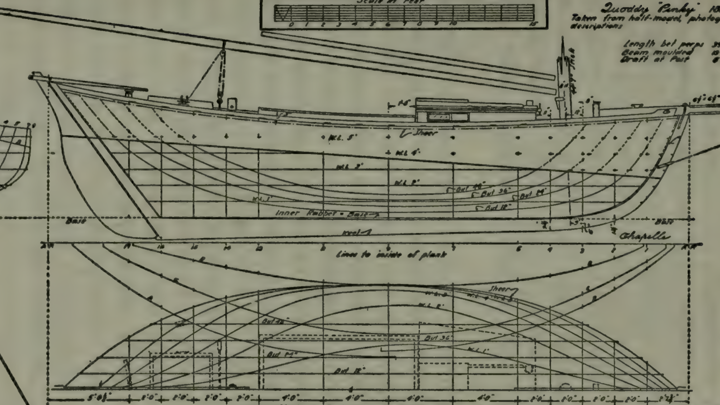
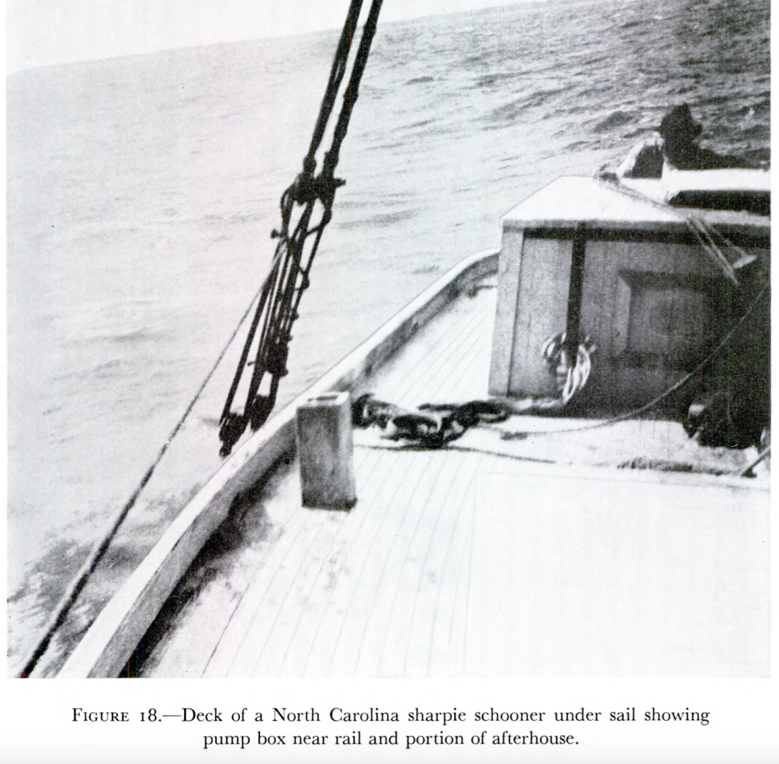
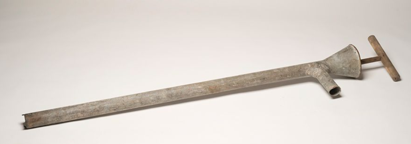
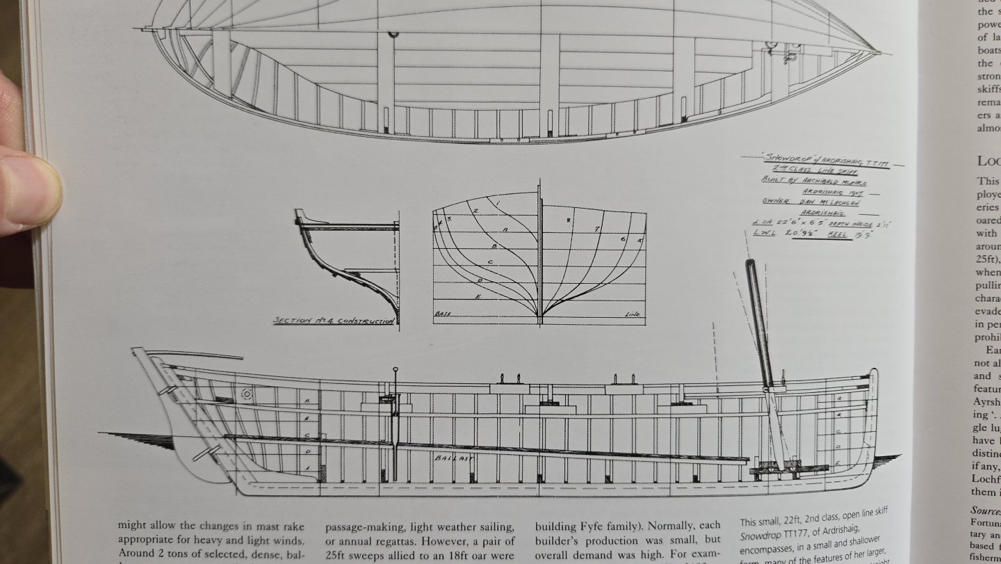
Thanks, all! Planking continues, slowly. Meanwhile, I’m thinking ahead to finishing up the cockpit. A key aspect of the boat’s equipment that is not included in the kit is the bilge pump. @Kenchington’s build includes a very interesting reconstruction of what this might have been like, but it’s worth noting that there are very few direct sources on this. The bilge pump does not appear in Chapelle’s plans, nor in the drawings of the sloop Ranger, nor have I been able to find a clear photo of it. The best I’ve been able to find is a photo of a replica Muscongus Bay sloop under construction in the 1970s, in which there is a hole in the cockpit floor next to the centerboard case, presumably for a bilge pump, but the pump itself is not shown. Most of the discussions of pumps on MSW focus on those used in larger ships, not in small workboats. So, some research is needed. What options are there? @Kenchington’s build includes an informative discussion, linked to below, in which he ultimately decided that an elm tree pump, discharging into a bucket in the cockpit, makes the most sense. This seems very reasonable to me, but 1) he hasn’t gotten to the handle yet, so I’m not sure what that would look like, and 2) I don’t want to just blindly steal from his ideas—at least not without learning a bit more about workboat pumps in the era first so I can better understand what I’m looking at. As I mentioned above, Chapelle’s plans of the Muscongus Bay sloop don’t show a bilge pump. In fact, I found very little about bilge pumps in most of his books—they’re barely mentioned in American Small Sailing Craft or Boatbuilding. American Fishing Schooners does include detailed drawings of wooden and iron pumps on pp. 571-582, but I’m not sure whether those designs would have been used on the much smaller sloop I’m modeling. Below, images from the book of a wooden pump and a diaphragm pump—as Kenchington suggests, the latter likely came into use a bit later than the period this model is supposed to represent. A few plans included in American Small Sailing Craft do depict pumps, although not in much detail. Most relevant, perhaps, as Kenchington notes, is that the construction drawing of a Friendship Sloop on page 273 shows some sort of pump in the cockpit, apparently emptying over the coaming, but it’s not clear what side it’s on, what the handle would look like, or whether it would be a round or square cross-section. His plan of a Quoddy Boat on page 263—especially relevant as it’s from Maine in the same time period as my model, although a rather larger vessel—also shows a pump, located just forward of the mainsheet, with an apparently round cross-section, although again the handle isn’t shown. Chapelle’s The Migrations of an American Boat Type (1961), a booklet on the development of the sharpie, does include the following photo of a square pump box on page 151, and the plans earlier in the book show that there was one on each side of the hull. (This detail is shown in Paul Le Wol’s excellent scratchbuild of a North Carolina Sharpie, by the way). The square shape is intriguing, but once again no handle is depicted. Looking beyond Chapelle, I also had a hard time finding much information. Nearly everything that I found was written with large ocean-going ships in mind, not small workboats. Skimming through Inshore Craft: Traditional Working Vessels of the British Isles by Basil Greenhill and Julian Mannering, though, I did find the following interesting depiction of a pump in a small Ardrishaig Open Line Skiff (pg. 18). The handle appears to be a simple loop rather than the more complex lever that appears in other pump depictions. An article on the Sgoth Niseach in a 1998 edition of Ships in Scale magazine shows something similar, but with a square- rather than round-sectioned pump. (Of course, these are from the UK, not the US, so I should take them with a grain of salt). Finally, searching on the Penobscot Maritime Museum site, I found this interesting galvanized pump. Unfortunately, it’s undated, although my understanding is that metal pumps are more likely to be from the 1900s and hence a bit later than my model. Source So, what can be made of all of this? There are two main questions that I have for my build. First, basic design. It seems that wood is the most likely material for the pump on a small workboat in c.1880s Maine, but I’m not sure whether a square or round cross section would make more sense. The round cross-section pumps were apparently made by boring out an elm tree, whereas I’m assuming that the square-section pumps were made out of planks. The latter option sounds to me like it would be cheaper (planks being widely available), but I’m not totally sure and would appreciate any suggestions. Second, the handle. While the big lever would certainly be easier to use, it takes up a lot of space, and this sloop has a pretty small cockpit. So, I think the options are either that 1) the pump uses a lever handle but the lever and associated mechanism can be removed, so as to not take up too much work space, or 2) given that this is a pretty small boat and the force to lift the pump would be relatively low, there’s no lever, just a simple crossbar (as on the galvanized pump above) or a loop handle). At the moment, I’m leaning toward the simple crossbar handle, but I haven’t decided on the square or round pump cross-section. Any thoughts or suggestions would be appreciated!

-
Great work on the pilothouse!
-
Welcome!
-
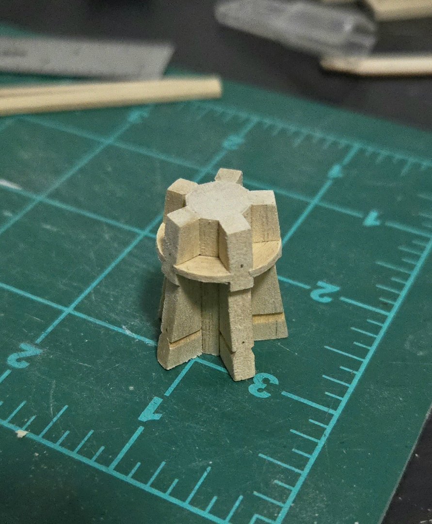
Very minor update: I liked the way the bolts on the capstan barrel assembly turned out, so I decided to do the same with the capstan step bolts. Rather than have them go all the way through, these are fake bolts only visible from the top side. I'll add pins to the lower side of the holes when the time comes to attach the step to the framing. It would be more accurate to blacken the bolts somehow, but I'm going for a more stylized look on this build anyway, so I'm happy with them looking more metallic. As can be seen, the step got a bit scratched up when I was filing down the bolts. So, I ended up lightly sanding the whole top with fine grit sandpaper and applying a new, light amount of linseed oil. Of course, it will take forever to cure, but it will be finished at about the same time as the capstan barrel. I also added a thin coat of shellac to protect the framework, the linseed oil on which has cured by now. Here's the whole assembly so far, minus the capstan bars: To cut out the capstan drumhead parts, I think I'll need to wait until I can get into the carpentry workshop to use the fretsaw there, so it will probably be a little while.

- 32 replies
-
- 12
-
-
- NRG Capstan
- NRG
- (and 1 more)
-
Nice progress! The black extending down from the bow chocks looks really sharp.
-
Thanks! I can see all sorts of ways I could be more precise. This build has been a great learning experience for me, and also very humbling. I think about how much time this single capstan has taken me, and then look at the amazing full-ship scratch builds on this site, many in a much smaller scale, with so many precise fittings and cuts. It blows my mind that people ever finish a full-ship build! It's also been very interesting to "mill" my own wood by hand. On one hand, it feels like a real accomplishment and I feel that much more invested in the model. On the other hand, it's an absolute ton of work, especially without the proper tools. Earlier I had been considering using the manzanillo for a fully-framed cross-section model, but by now I think that milling the lumber to size would be way too much work to be worthwhile, except maybe for some select parts. (Not to mention that the manzanillo's grain is a little more prominent than I would like, and I've found that the dust irritates my nose a bit if I do substantial sawing or sanding indoors.)
- 32 replies
-
- 7
-
-
- NRG Capstan
- NRG
- (and 1 more)
-
Very nice work! (Not just on this, but throughout the model, it's an extraordinary build.) Can the windlass rotate, or is it stationary?
-
I drilled out the bolt holes next, and then gave it a final sanding. For the bolts, the ones through the whelps should be thicker than the ones through the chocks. Rather than try to exactly match the dimensions at this small scale, I decided to go for a general impression, using annealed wire in 24 and 28 gauge. Finally, I drilled pilot holes in the top and bottom, and applied a linseed oil finish. In my experience, the linseed oil will even out a bit and look better tomorrow.


- 32 replies
-
- 10
-
-
- NRG Capstan
- NRG
- (and 1 more)
-
The Nautical Research Journal has an article in Vol. 20, No.1 by Ben Lankford titled "The Rig of a Scow Schooner." I bought the pdf version a while ago. He mentions reconstructing typical block sizes based on Steel, Kipping, and other "standard tables." The drawing seems to include block sizes, but it's hard to tell--in the pdf version, the drawing is blurry. I've included a small portion of the image below. Assuming the numbers next to the blocks are in fact their sizes, it looks like the main sheet used 12- and 13-inch blocks, 8.5-inch blocks were used at the aft end of the main boom for the main top lift. Elsewhere it looks like 10- or 10.5-inch blocks for used for the gaff halyards, 6.5-inch for the topsail halyard, and even some smaller ones elsewhere. (This is, of course, a very rough summary based on some very blurry text, so take this with a grain of salt). The full article may be useful to you, as it can be ordered for pretty cheap through the NRG store, but you'd have to decide whether the blurry drawing is a dealbreaker. (It also includes a belaying plan and other detailed drawings, though without dimensions, that are a bit larger and very slightly clearer.)

- 48 replies
-
- 1
-
-
- San Francisco Bay Scow Schooner
- Scow Scooner
- (and 1 more)
-
For the lower chocks, made with a thicker strip of manzanillo, I trimmed them closer to final size before gluing. I still left them slightly oversized, though. I then sanded them to final shape. They should be slightly concave. At this point, I need to drill the bolt holes, do a final careful sanding at a finer grit, and then apply a finish to the barrel assembly. Edit to add: And here it is resting on the capstan step.


- 32 replies
-
- 12
-
-

-
- NRG Capstan
- NRG
- (and 1 more)
-
Nice work on the 3-model series! Given that you built one already, do you think you'll be kitbashing this build?
-
Thanks! I used an x-acto knife to pare down the excess chock material, and then sanded it down. It was a little tricky to hold the barrel assembly while carving, so for the lower chocks, I think I'll try to trim them nearly to the right size before gluing. I also sanded the top and bottom of the barrel assembly, bringing it down to the right size. These upper chocks should be somewhat rounded, as can be seen from above.

- 32 replies
-
- 9
-
-
- NRG Capstan
- NRG
- (and 1 more)