JacquesCousteau
-
Posts
1,383 -
Joined
-
Last visited
Content Type
Profiles
Forums
Gallery
Events
Everything posted by JacquesCousteau
-
 Fantastic job! I know from my experience with the Midwest Peapod kit that the strip planking can be a little tricky to get smooth, you're doing an exemplary job of it.
 -
Looking good! You may want to check further ahead to see if having the bulwarks too low aft will cause problems later in the build. If not, I think the main issue is that the bulwark is sticking out a ways. Before cutting that part off you could try soaking it and seeing if you can bend it (maybe with a pin) to bring it back in contact with the bulkheads.
-
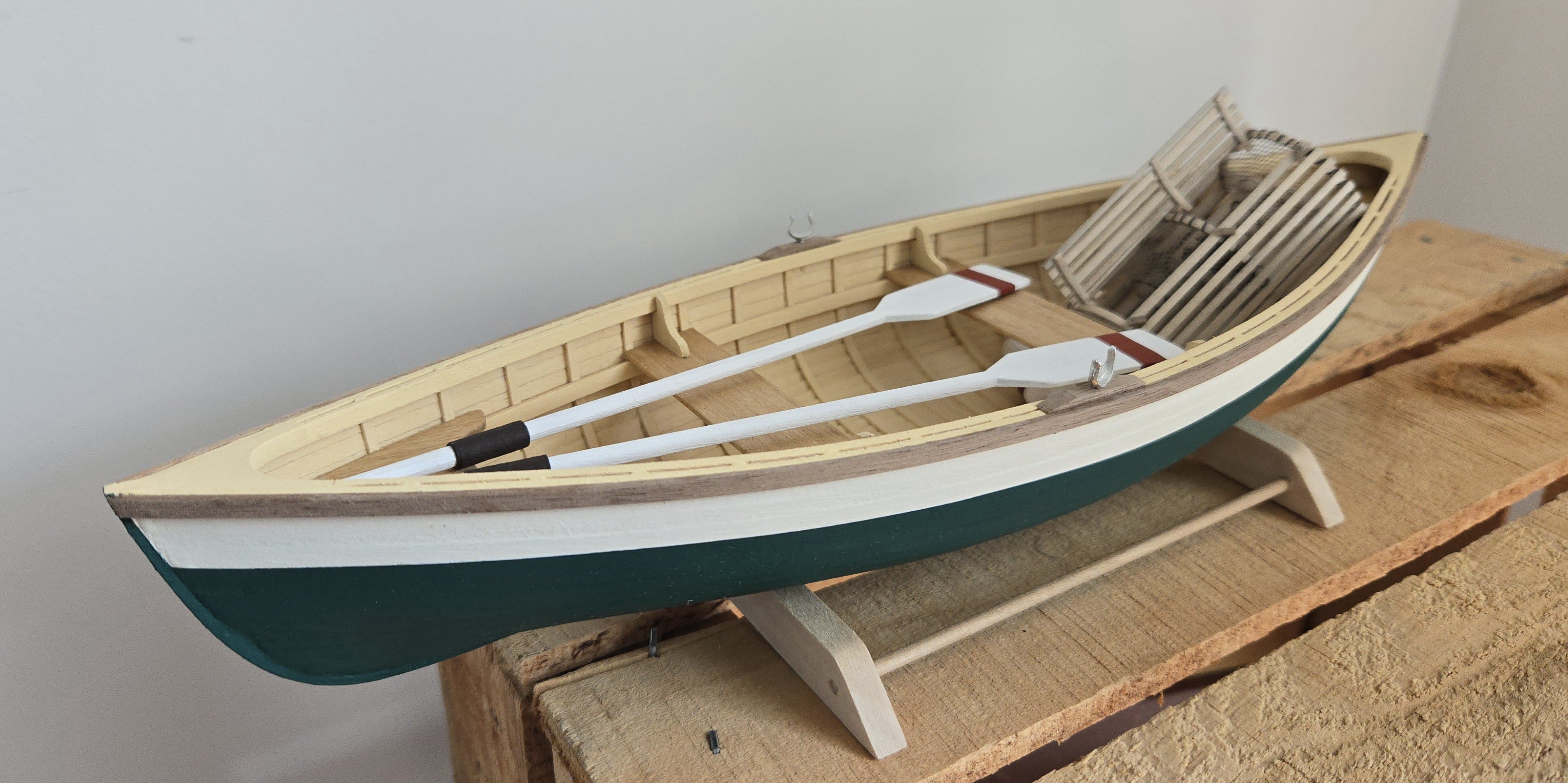
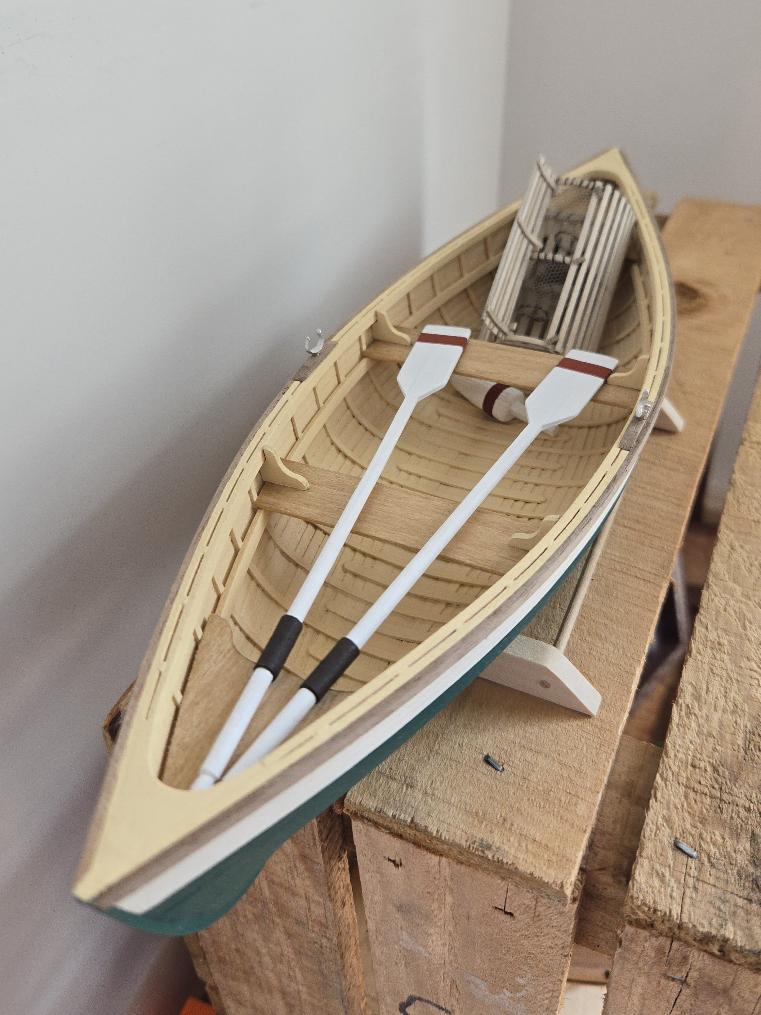
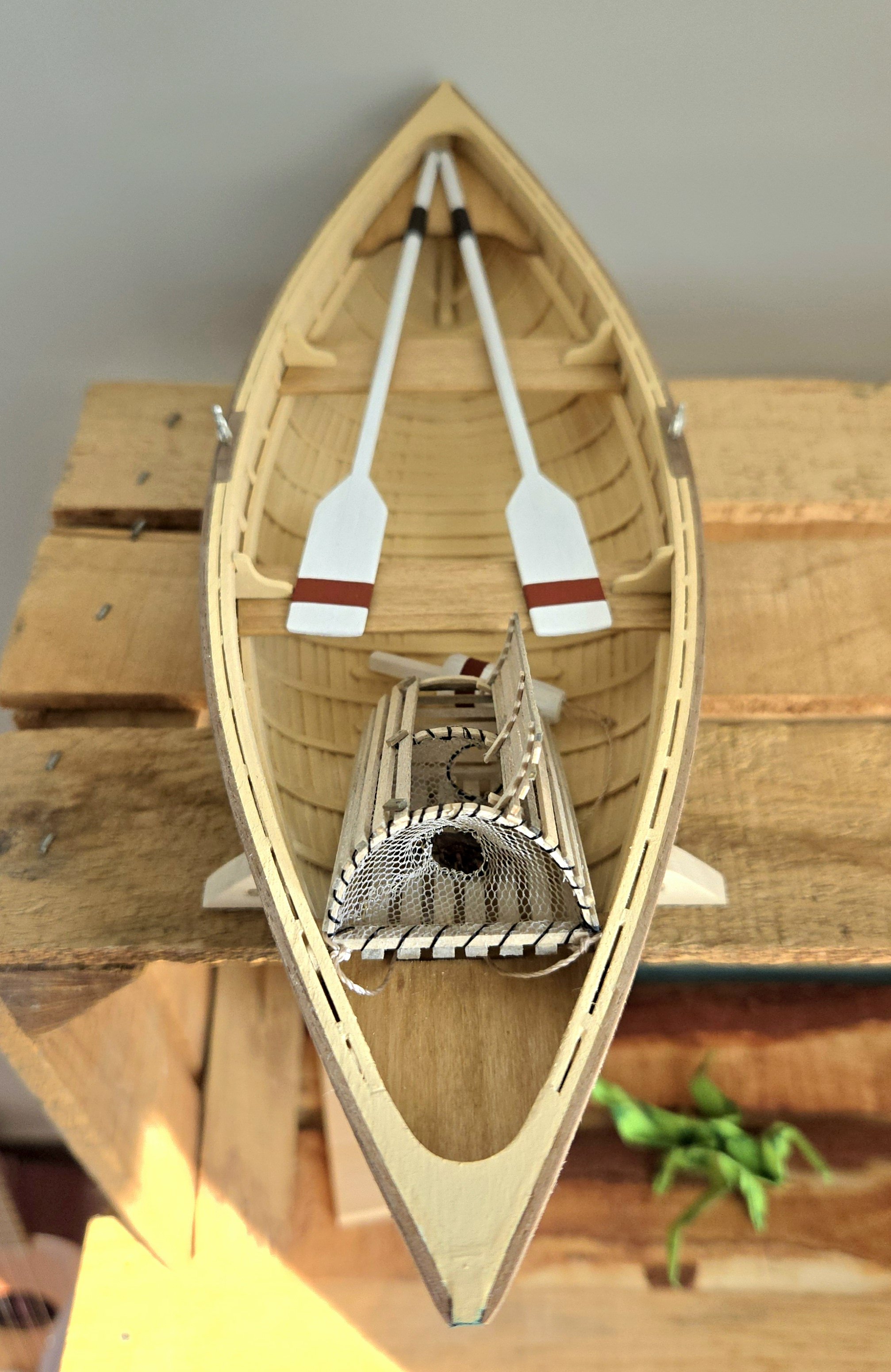
And here's the completed build: Although it took a while to build this when measured from start date to end date, that's mostly because I was quite busy with work/other builds/an international move while making it. Overall, I thought this was an excellent kit. It was a lot of fun to put together, and I think it turned out pretty well. The instructions are generally very good, although they could be clearer on the planking. I found the strip planking system to be pretty easy to do, but it was a challenge smoothing out the interior of the hull. The wood was generally good, while the castings were decent (although I still think a wooden buoy would have worked out better). I do think the suggested lobster trap is very oversimplified and oddly-proportioned, but it's not all that hard to scratch-build something better with the parts. I wouldn't hesitate to recommend this kit.


- 65 replies
-
- 12
-

-

-
- Maine Peapod
- Midwest Products
- (and 1 more)
-
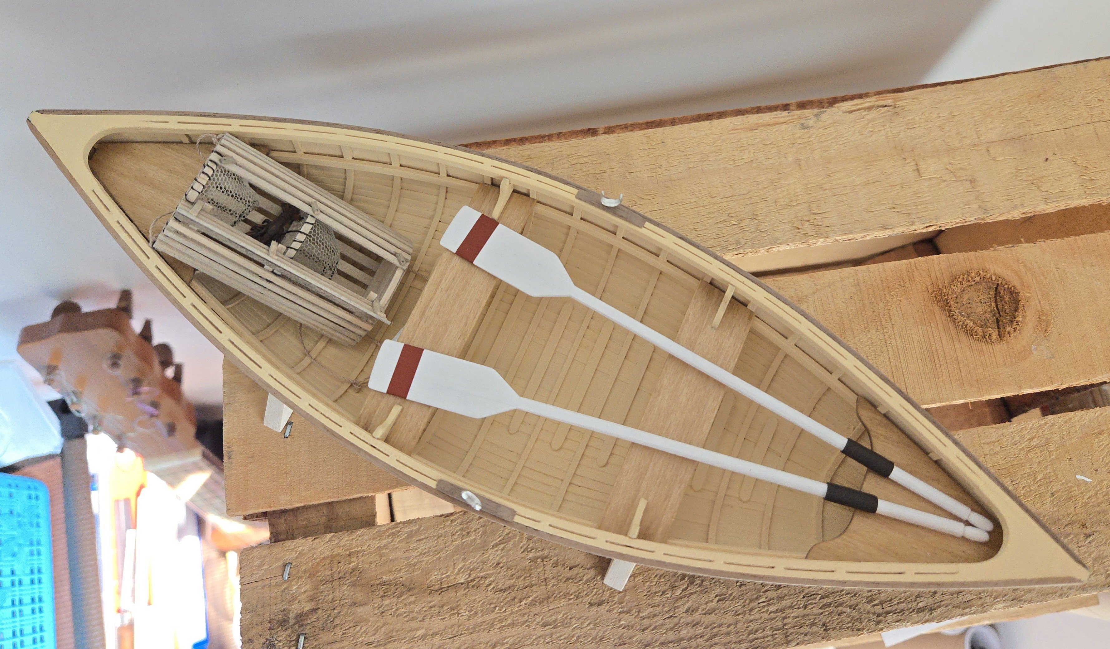
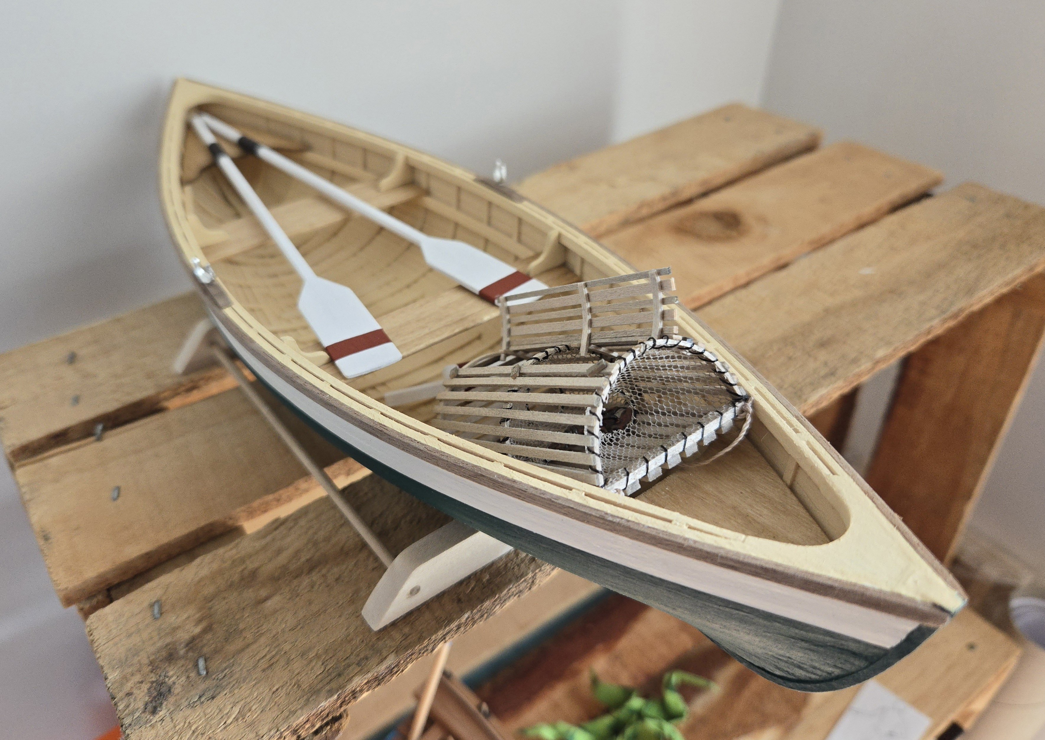
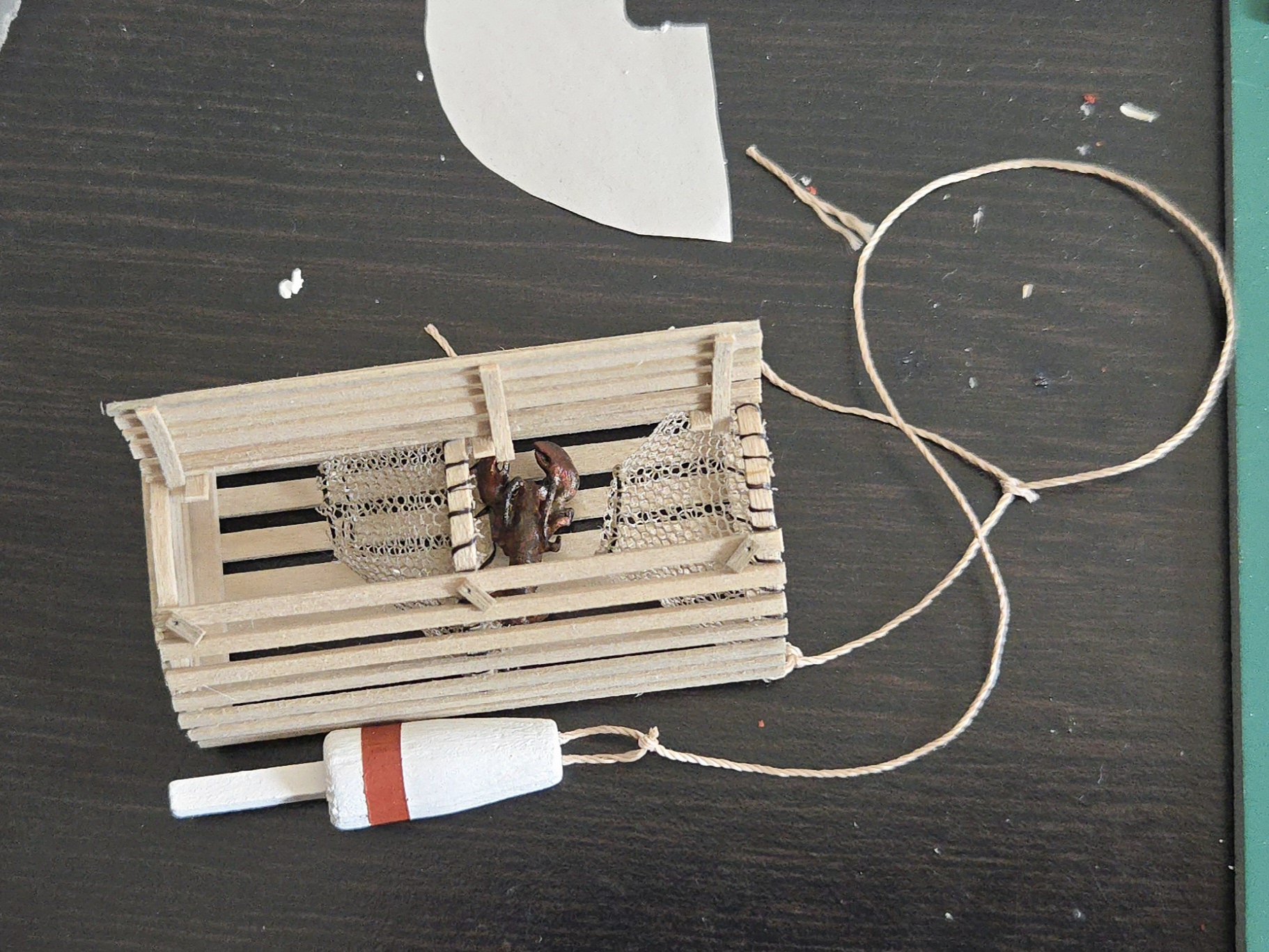
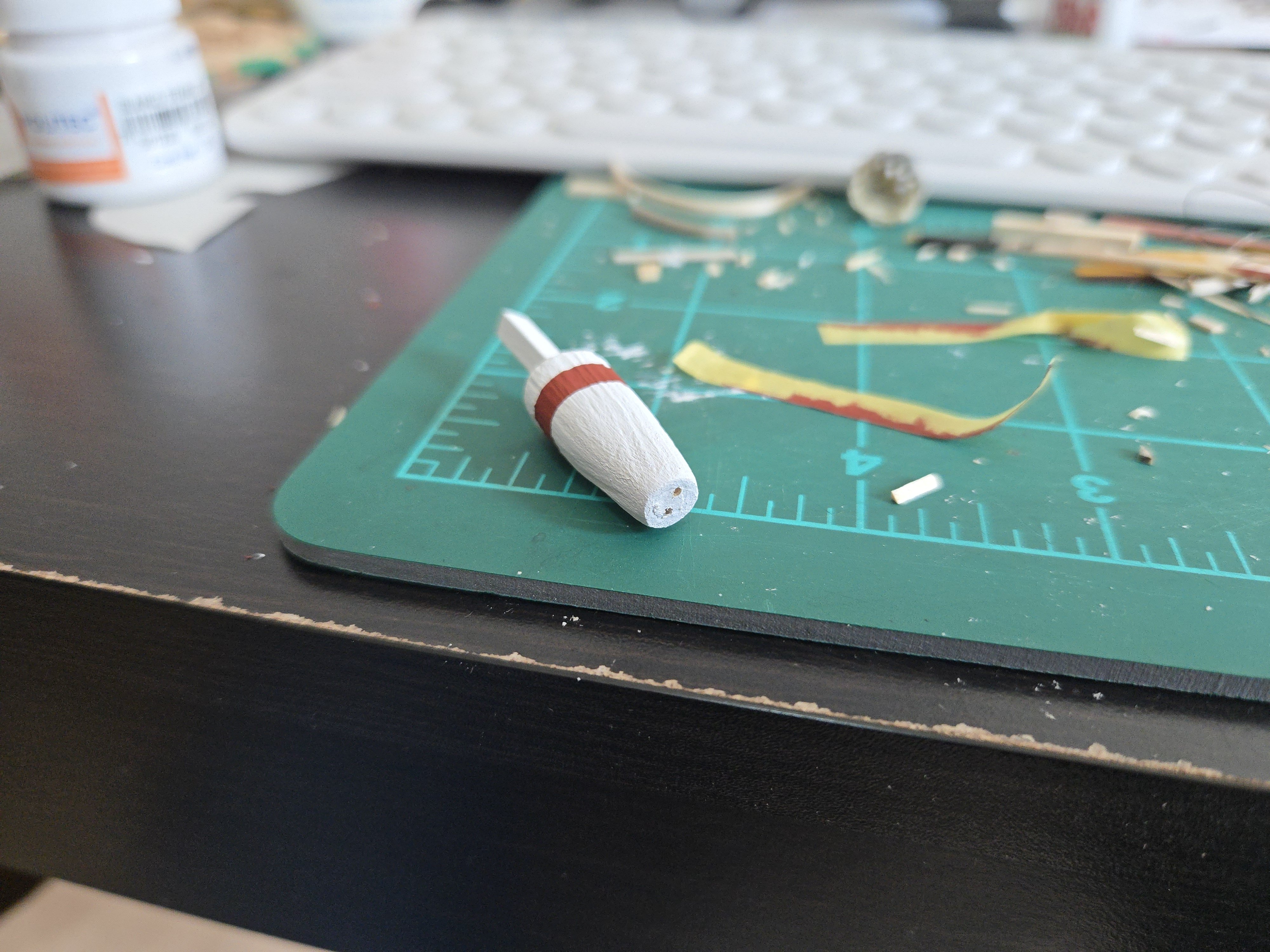
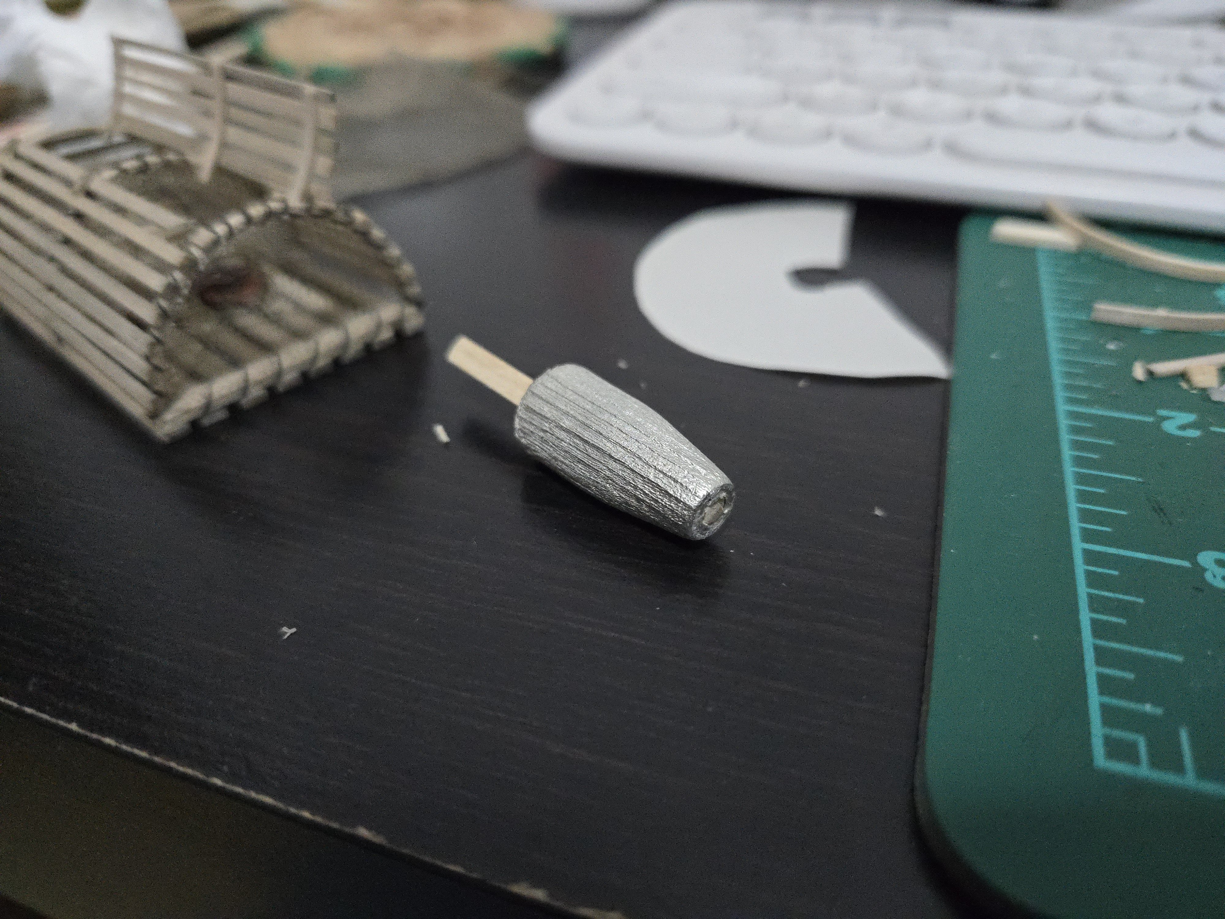
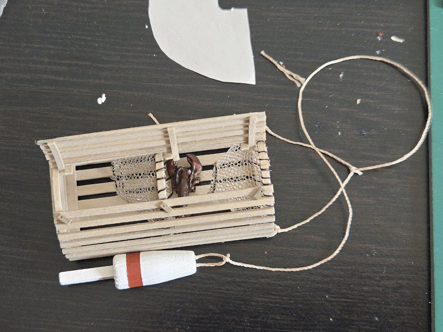
Thanks, all. This build is finished! (For some reason it gave me trouble when I tried to upload all the pictures, so I'm splitting this post in two.) First up, I finished the lobster trap. The open door was a fun addition. I used the leftover broken hoops to make the curved frame parts. I then glued the door in the open position. I also added some extra framing parts for the hinges, and three small pivoting "buttons" used to secure the door. Finally, I made the front net funnel using the same method as the previous one. As for the buoy, I followed @Desertanimal's suggestion and rounded off part of the wood to fit in the round hole. I decided to simply fill in the front, and drill two joles later for the rope loop. The buoy looks better painted, although the molded-on grain is still a bit excessive (and made it a little tricky to tape off and paint the red stripe). In any case, the buoy will be partly hidden under a thwart, so it's not a problem. I then glued the lobster in place. While it struck me as pretty cheesy when I first got the kit, I have to admit that I warmed up to it. Finally, I attached the ropes to connect the trap to the buoy, using the kit-provided thread.


- 65 replies
-
- 4
-
-
-
- Maine Peapod
- Midwest Products
- (and 1 more)
-
Very cool! Nice job on the completed builds, and I'm looking forward to seeing following along on the new one. It's fascinating to see the variety of workboats from the Chesapeake, although I have to admit that I don't really know the difference between them all (box stern vs round stern, for example).
-
Very inventive use of the dryer sheet, it looks great!
- 185 replies
-
- 7
-

-
-
- Flying Dutchman
- Black pearl
- (and 2 more)
-
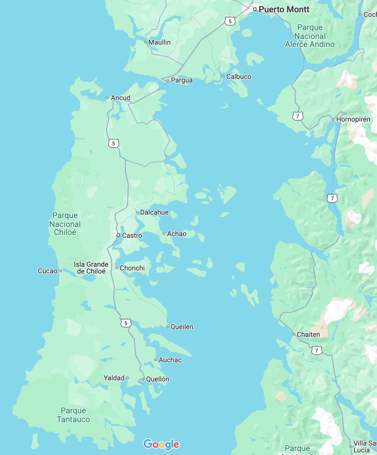
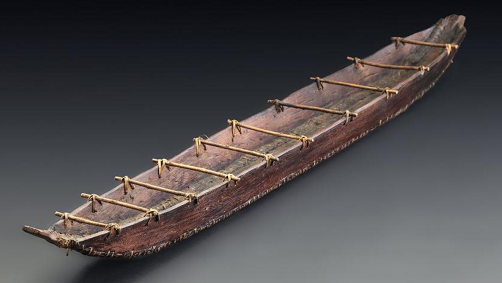
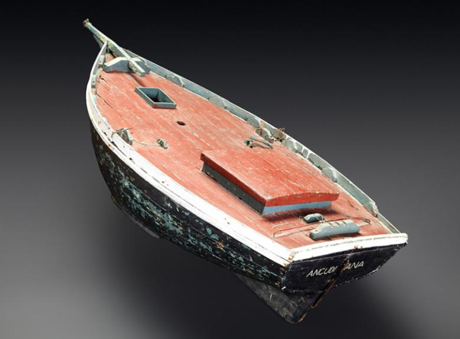
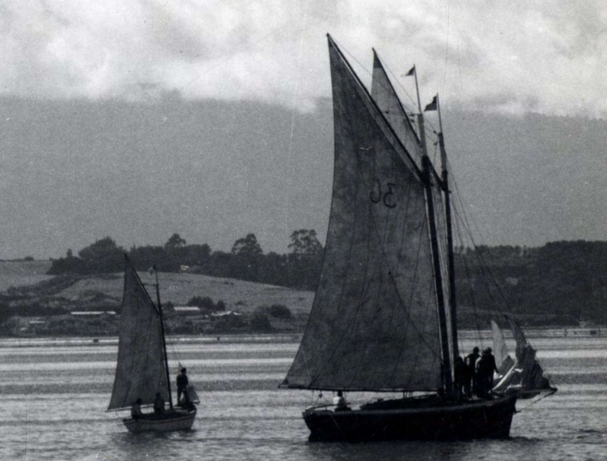
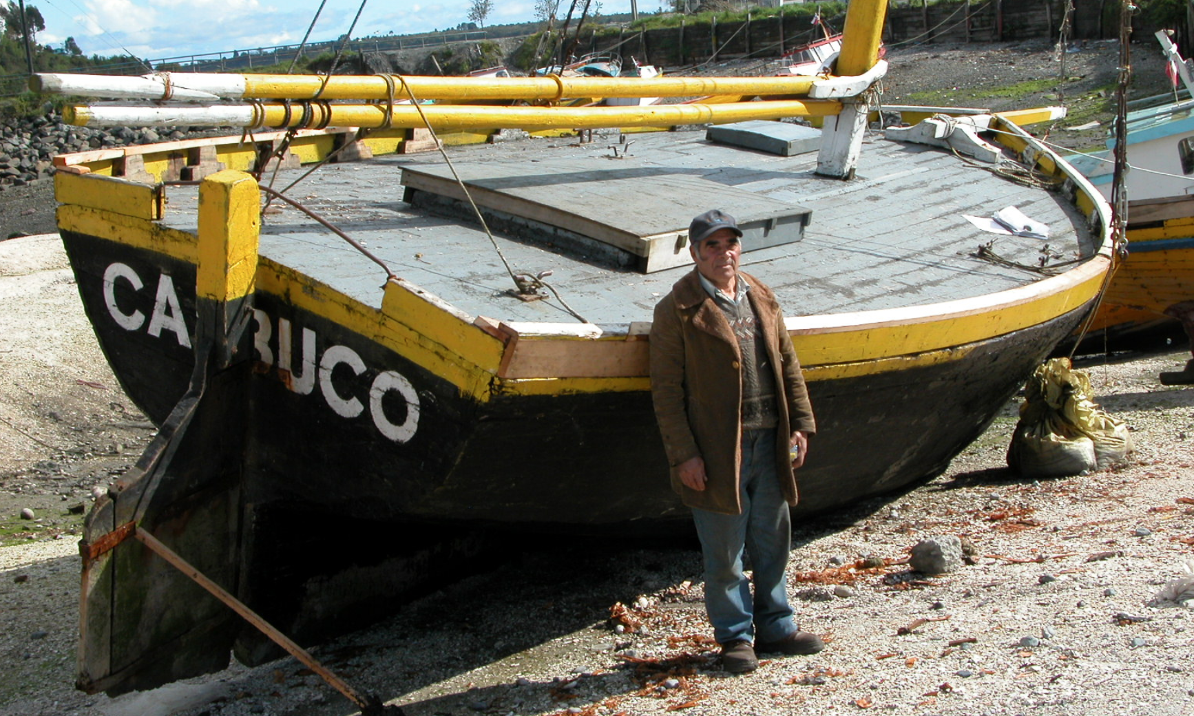
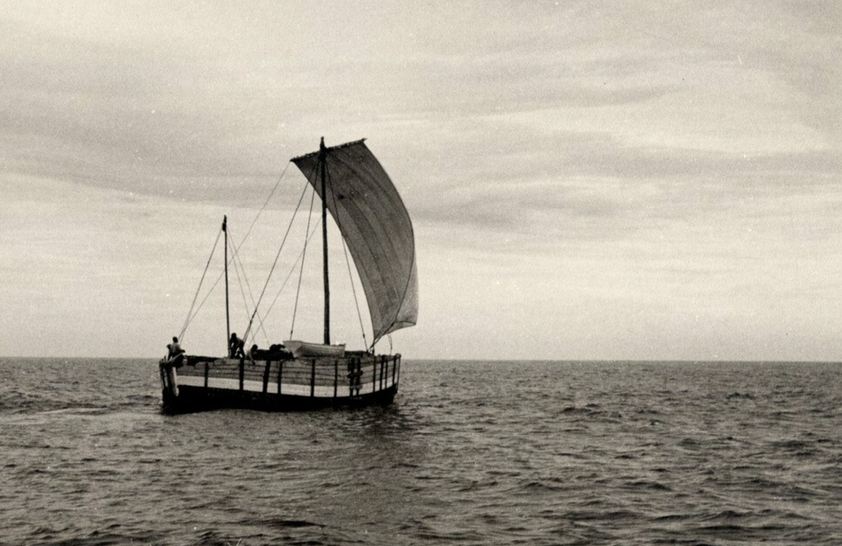
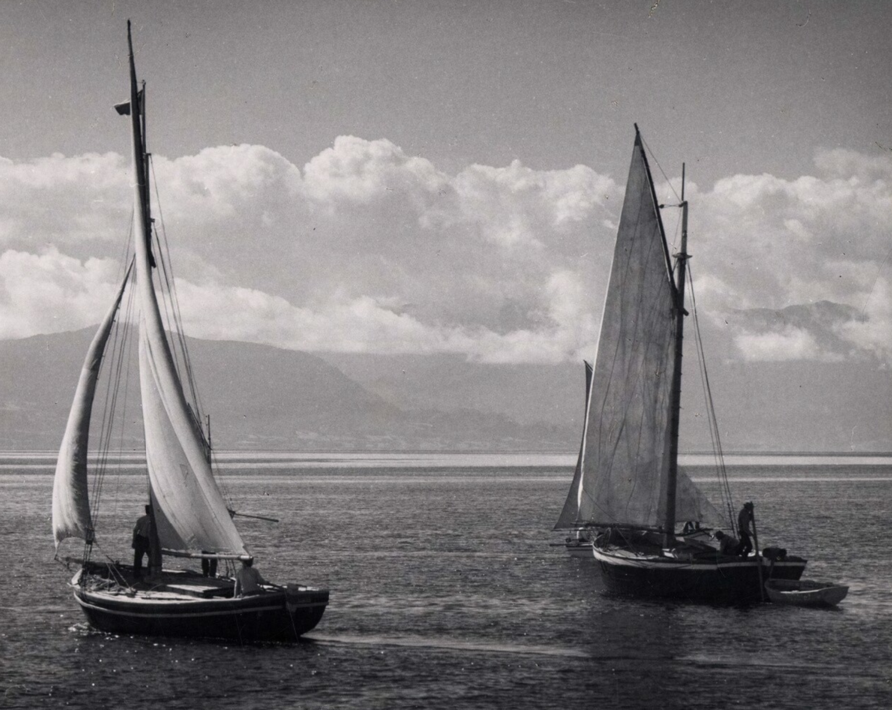
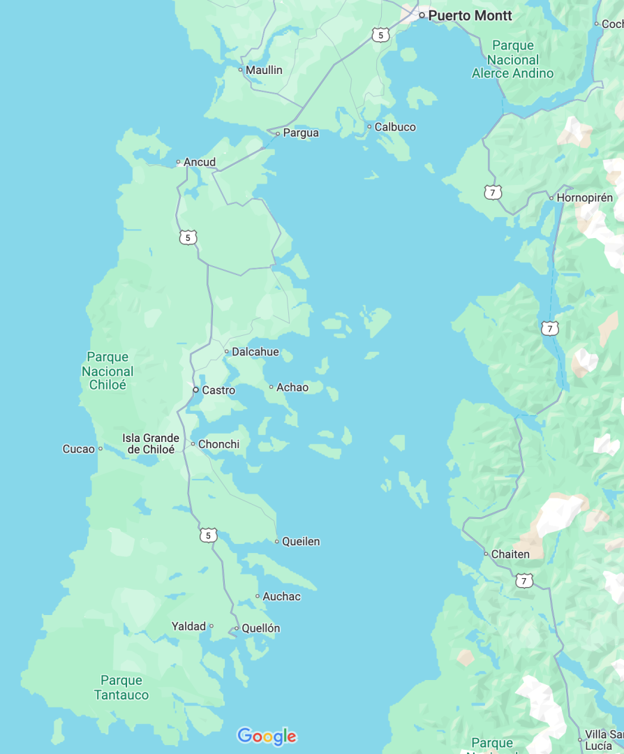
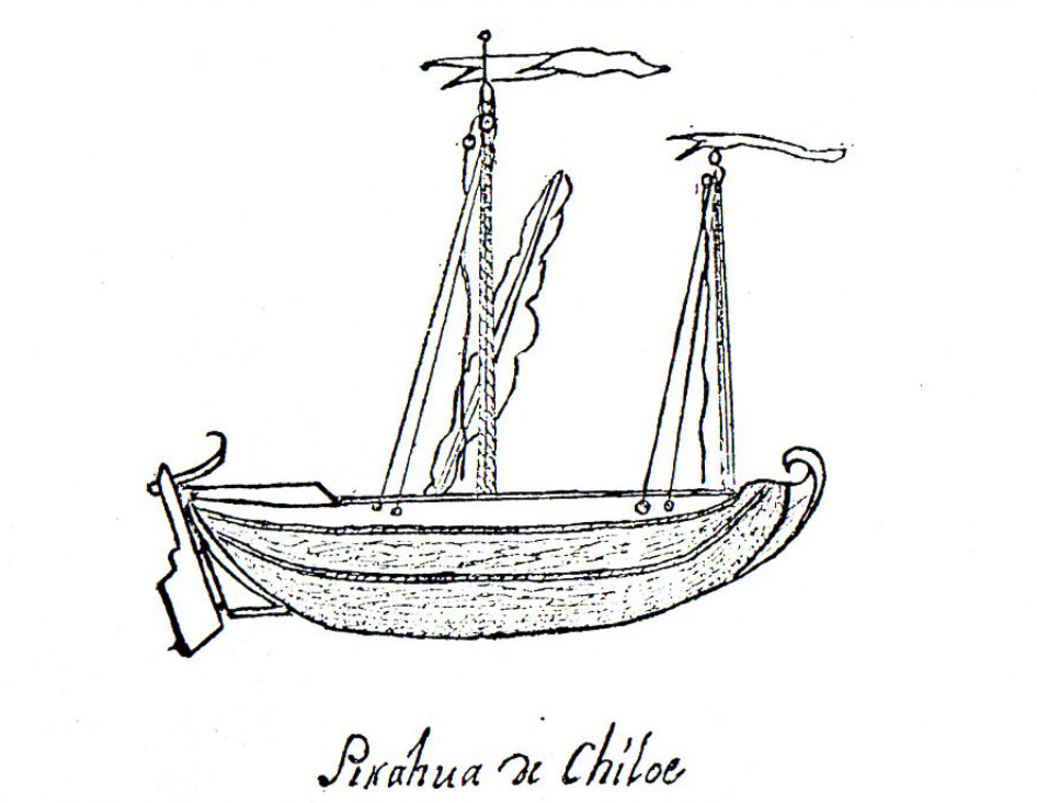
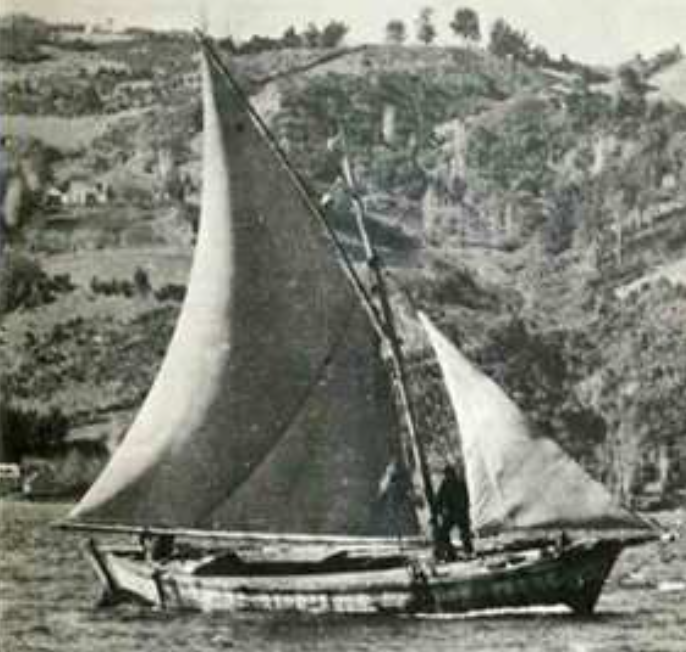
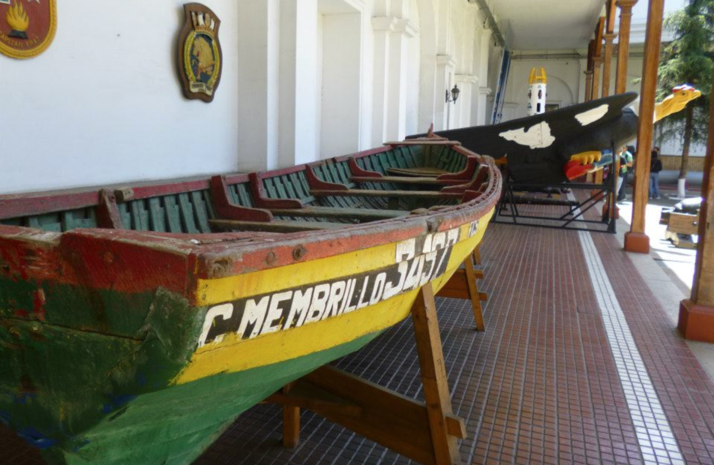
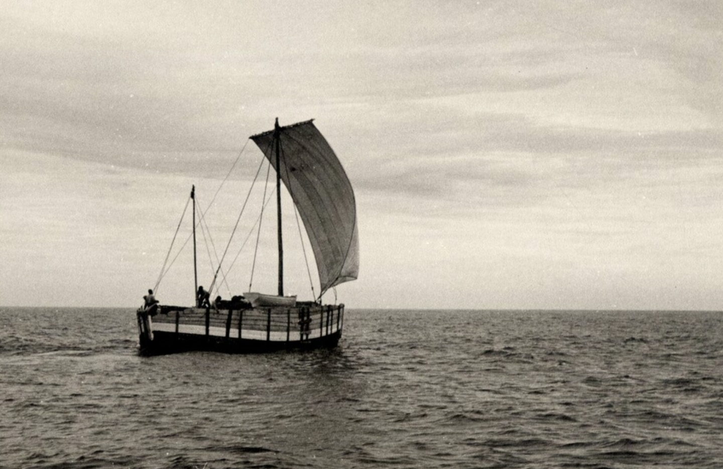
By now I’ve talked about why I chose to build a lancha chilota, and about what sources I am using to guide the build, but I haven’t talked much about the boat itself. In this post, I’ll be talking more about the lancha itself and its development. I plan on further developing the type’s history and its context in future posts on more specific aspects of the boat, mixed with the discussion of the build. Once I have a few of them, I may add an index to the first post, probably not to track all the parts of the build, but to link to the different posts on contextual information. The Lancha Chilota: History and Context (Anton Daughters’ Memories of Earth and Sea is a crucial source for the contextual information that follows.) Understanding how the lancha chilota emerged requires some geographical and historical context. The type developed not just in response to a particular geographic environment, but also in response to economic, social, and technological changes in the late nineteenth and early twentieth century in the Chiloé region. In many ways, the lancha chilota is a material representation of the changes that reshaped Chiloé in this period, as the region became connected to the market economy and shaped by contact with the rest of the world to a much greater extent than at any earlier point in its history, undergoing the most rapid period of change it had experienced since Spanish colonization centuries prior. The history of how the lancha chilota came to be helps us to understand the meaning of these big-picture developments in people’s day-to-day lives, as they adapted to their changing circumstances as best as they could. The lancha chilota developed in the Chiloé region of southern Chile, just north of Patagonia. In fact, “lancha chilota” (which is pronounced, if you’re curious, like “LAUNCH-uh chee-LOAT-uh”) literally just means “Chiloé-an boat.” (“Chilote” means “person or thing from Chiloé”). The Chiloé Archipelago is dominated by a large island of the same name, but includes dozens of small islands scattered in the Sea of Chiloé to the east of the big island. The archipelago is heavily forested, while the surrounding mainland is mountainous and dotted with fjords, rising rapidly to the peaks of the Andes. To the south, the Gulf of Corcovado separates Chiloé from the Guaitecas Islands and the Chonos Islands. The climate is temperate but rainy and cool. Chiloé today is known for its vibrant cultural traditions, which are quite different from the rest of Chile, as well as its distinct architecture. It’s at the heart of Chile’s fish farming industry, which is today the world’s second-largest. It’s also home to some 400 native varieties of potatoes, a bit of trivia I find astounding. Source: Google Maps. At the time of Spanish colonization, the Chiloé Archipelago was populated by two indigenous groups. The Chono people of southern Chiloé and islands further south were highly mobile and nomadic, living off of the sea, while the Huilliche in the north lived in more sedentary villages and practiced agriculture alongside fishing. For seaborne travel, trade, and fishing, both groups made extensive use of Dalcas, canoes up to 30 feet long made by sewing together planks which could be easily disassembled for transport on land. The dalca was a highly unique vessel: only one other indigenous people in the Americas, the Chumash of California, made use of the sewn-plank technique, although the dalca differed from the Chumash tomol canoe in being made of just three large planks instead of many small ones. Planks were made by using wedges to split logs, and then by laboriously scraping the result to size and shape with stone and shell tools, producing one to two planks per tree. (Here I should note that quite a bit has been written about the dalca, but I’m hoping to model one in the near future, so I’ll save a full discussion for then.) Below: Model of a pre-hispanic Dalca in the Ancud Regional Museum. Source: https://www.museodeancud.gob.cl/galeria/representacion-de-una-dalca After Spanish colonization in 1567, Chiloé became a very marginal colony on the fringes of the empire. The archipelago was largely cut off from the rest of Chile after the Mapuche uprising of 1598 on the mainland north, becoming more connected to Peru instead through an annual trading ship. In fact, after the rest of Chile gained its independence, Chiloé (which was officially transferred to Lima’s jurisdiction in 1767) remained the last royalist stronghold in South America. While food was fairly abundant on the island, there were few other resources for the Spanish to exploit for export besides lumber. The local economy mostly ran on the barter system, and the encomienda labor system used elsewhere in the empire was relatively weak (although encomienda abuses did provoke a Huilliche uprising in 1712, which was bloodily suppressed). Most Chilotes’ livelihoods were based on small-scale farming and fishing, carried out in part through the minga, a Huilliche-origin system of reciprocal obligatory labor (e.g., one day you help out your neighbor with a harvest, and they later help you out, in an endless cycle). Colonial society blended indigenous and Spanish practices—even Spaniards there largely spoke indigenous languages, for instance, and steel and iron were rare enough that most woodworking and lumber production continued to use and adapt indigenous techniques. Chiloé’s wooden churches, which have been listed as a UNESCO World Heritage Site (https://whc.unesco.org/en/list/971/ ), made limited use of nails, for instance. The Spanish also fully adopted the dalca (which they often called a “piragua”), finding it useful not just for cargo hauling and fishing, but also for expeditions to chart the rugged Chilean coast, as its easy disassembly meant it could be hauled overland. Its sewn construction allowed it to be built with minimal use of steel or iron, which were in short supply in the impoverished colony. Observers from even the late colonial period noted that lumber milling continued to employ labor-intensive indigenous techniques due to the lack of other tools. In the colonial era, the dalca was modified by sewing on extra strakes to add to the freeboard and adding square sails, frames, a skeg, and a false stem (all mortise-and-tenoned together), in order to create five- and seven-plank vessels of up to 60 feet long (although smaller three-plank dalcas remained common as well). By 1787, an official census registered some 472 dalcas in the region, among a population of 24,000, and they were vital for communications and trade (Source: Manuel Puente Blanco, “La ‘dalca’ de Chiloé. Su influencia en la exploración austral. Contribución a su studio.” Revista de Historia Naval 15 (1986): 19-44.) Below: Image from 1793 of a two-masted, seven-plank colonial dalca. Source: Image shown in Puente Blanco, “La ‘dalca’ de Chiloé,” pg. 29. As Daughters argues in Memories of Earth and Sea, many colonial patterns continued well after independence. Chiloé remained marginal to Chilean society, and the economy continued to be dominated by small-scale farming and fishing, barter, and the minga reciprocal labor system into the twentieth century. Settlements were widely scattered across the archipelago, and land transport remained limited until quite late, making sea transport necessary. Cultural identities remained quite distinct from the rest of Chile, too, with Chiloé developing its own folklore and maintaining many colonial-era customs. However, there were some changes in the late nineteenth and early twentieth century that are important to understanding how the lancha chilota developed. Daughters doesn’t place very much emphasis on them, because he’s trying to explain the broad sweep of Chilote history and finds the Pinochet dictatorship of 1973-1990—which witnessed the decline of small farming, boom and bust cycles in the fishing industry, the rise of large-scale fish farming, and practically a complete shift to wage labor—to be much more transformative of Chiloé overall. His view is solidly supported, but the lancha chilota’s emergence is only explicable if we look at what changed earlier in the late nineteenth and early twentieth century. The population of the region—especially on the nearby mainland—grew from the mid 1800s onward, especially as the Chilean government promoted the formation of colonies of European immigrants to develop what was then a frontier region. Economy and society also changed. While the minga wasn’t wholly replaced, the economy slowly began to shift from barter to cash, although this transition was still only partial by 1900. Cash was useful for buying tools and goods, especially ones that were produced elsewhere in the country (or were imported) and which increasingly became available in major markets, especially in ports like Puerto Montt. Faced with a growing need for cash, but living on a cash-poor island with a largely subsistence-based economy, many Chilotes began to seasonally migrate to the mainland for itinerant work. Many found their way into the lumber industry centered on cypress production in Patagonia and mainland Chiloé, as demand for lumber skyrocketed with railway construction, Chilean economic growth, and foreign investment. New technologies were also implemented, albeit slowly, with a narrow-gauge railway being constructed on the island in 1911 and national railway lines reaching Puerto Montt around the same time. The growing lumber industry also undoubtedly made new milling tools and standardized planks much more widely available. So, in the late 1800s and early 1900s, Chiloé was in something of a transition, becoming less autarkic with increasing trade (still largely in lumber) around the archipelago and with the mainland and with growing connections with the rest of Chile and the outside world. In this context, the dalca, which continued to be used well into the 1800s, gradually came to be replaced. The dalca’s decline was due to several factors. While there was growing demand for trade and transportation, dalcas were not very efficient cargo haulers, being long and narrow with little cargo capacity, requiring a large crew to row whenever they needed to travel upwind, and often being leaky enough to require a dedicated bailer. At the same time, dalcas also required very large planks, given that each plank had to stretch the entire length of the vessel, but the growth of the lumber industry likely meant that smaller, more standardized planks became much more common and more efficient to use. Finally, with growing trade in the region, metal fasteners likely became much more common, obviating the need for sewn construction. Under these pressures, the dalca disappeared, taking with it knowledge of an entire boatbuilding tradition. The dalca was replaced by a number of new types of vessels constructed according to European-style plank-on-frame techniques, of which the lancha chilota was just one. Chiloé was an important center in the whaling industry in the early-mid 1800s, and the Euro-American whaleboat influenced the development of the double-ended open Chalupa, and its larger, partially decked cousin, the sloop-rigged Chalupón. These became common around the region and further south, often being used for fishing, sealing, and in the lumber trade. (The chalupa and chalupón have been the subject of an interesting and informative recent book: Felipe Rodríguez Cerda, Casa-mar. La chalupa a vela en la Patagonia insular occidental. Santiago: Servicio Nacional de Patrimonio Cultural, Colección de Etnografía, 2022. It discusses the impact of the whaling industry on the development of the chalupa on pages 56-63, and the Patagonian lumber industry in the late nineteenth century and its use of small vessels on pages 68-73. The book is available for legal download here: https://www.investigacion.patrimoniocultural.gob.cl/publicaciones/casa-mar-la-chalupa-vela-en-la-patagonia-insular-occidental ) Below: Replica chalupa in the Ancud Regional Museum. Source: https://www.surdoc.cl/registro/22-1160 Below: Chalupón under sail. Note that the vessel is double-ended and only partially decked, unlike the lancha chilota. Source: Trace Gale, Gabriela Espinoza, and Jimmy Valdés. “Expediente: construcción-navegación en chalupa a vela Guaitecas-Zona Litoral.” Consejo Nacional de la Cultura y las Artes; Centro de Investigación en Ecosistemas de Patagonia. 2013. The lancha chilota also developed in this period, specifically for the coastal trade. Its development was a material marker of Chiloé’s changing economy and society in the late nineteenth and early twentieth centuries. As Felipe Rodríguez Cerda suggests for the Chalupa (pg. 73), the lancha responded to the growing need, with expanding trade and the rise of the market economy, for a more seaworthy vessel than the dalca, as well as to changing woodworking techniques and the growing availability of new materials with the development of the lumber industry and trade in metal fittings and fastenings. The lancha seems to have been more specialized for cargo hauling than the jack-of-all-trades chalupa. It had a broad hull to maximize cargo space, a prominent main hatch to allow easy cargo handling, a full deck to protect shipments and passengers, and a gaff rig for weatherly sailing. The lancha was also relatively simple to build in isolated settlements, which was a must—while there were some larger vessels and bigger businesses in the lumber trade, most lanchas were family affairs, as Hollander and Mertes’ The Last Sailors makes clear. It could also be sailed with minimal crew, being much more efficient in this regard than the dalca, which, being keelless, had required a number of rowers to move against the wind. Lanchas were usually around 8-10 meters (26-33 feet) in length and quite beamy, with a relatively shallow hull and the ability to be safely beached at low tide—they had a sort of bumper plank, called a “guarda playa,” around the turn of the bilge for this purpose. Although I’ll deal with the question of origins in a later post, the lancha may have been directly influenced by nineteenth century European designs, possibly through immigration to the region. Below: Model from 1976 of a lancha chilota, displaying the type’s beamy, capacious hull form. The guarda playa “bumper” plank is just visible at the turn of the bilge. Ancud Regional Museum. Source: https://www.museodeancud.gob.cl/galeria/modelo-de-lancha-chilota The lancha chilota was extensively used, as photos showing crowded harbors attest, hauling cargo and carrying passengers around the archipelago for decades. The inhabitants of isolated towns often traveled by lancha, crowding into its spartan hold and huddling around the small stove that was usually carried, on their way to larger port cities like Puerto Montt to sell firewood and other products, and to buy goods that they couldn’t easily produce themselves—tools, consumer items, eventually mass-produced clothing, etc. For many, the lancha was the crucial link between their home communities and the wider world. In a very practical sense, their experience of what it meant to live in the modern world was created through the lancha (and similar vessels like the chalupón) and the increased connections that it fostered. At the same time, as explained above, the lancha itself was the product of these same processes of change, encapsulating new building techniques, the availability of new materials, and displaying influences from beyond Chiloé’s shores. The lancha chilota’s heyday lasted for several decades before coming to an end. The design underwent some changes over the years that I’ll discuss in a later post, until being replaced by motor vessels in the 1960s and 1970s. Expansions in terrestrial transportation also put pressure on seaborn trade—indeed, one lancha owner documented by Hollander and Mertes in The Last Sailors happily noted that he wanted to sell his vessel as firewood because he now had a steady job nearby in highway construction—although the rugged terrain and sheer number of islands mean that Chiloé continues to be a highly maritime society. Today, there is renewed interest in the lancha for a number of reasons. Its revival is seen as a way of spurring tourism and the economy while helping preserve traditional woodworking skills and techniques, at a time when Chiloé has been quite thoroughly changed by the rise of the cash economy and the development of large-scale fish farming. (It’s interesting that the lancha has received much greater heritage and reconstruction interest than, say, the dalca or the chalupa. It may be that its decked construction makes it a more complex expression of the boatbuilder’s craft than an open vessel like the chalupa, and some builders still survive, unlike with the dalca. Perhaps it’s also that its design is more readily adapted to include a roomy cabin to serve as a yacht.) Interestingly, many workboats in Chiloé continue to be made of wood to the present day, with many motor vessels sharing similar hull designs and construction techniques with the lancha. Below: Two lanchas and a smaller vessel near Puerto Montt in 1959. Source: Lanchas chilotas. 1959. Photographer: Domingo Ulloa (1925-2018). Available in: Archivo Fotográfico. Biblioteca Nacional Digital de Chile https://www.bibliotecanacionaldigital.gob.cl/bnd/635/w3-article-164290.html So, while the lancha chilota is a “traditional” workboat, it’s hardly timeless. Viewed from one angle, it’s just one chapter of many in Chiloé’s long history with the sea; viewed from another, the lancha’s rise marked a major shift in that relationship. Its development, and its specialized cargo-hauling design, tracks changes in and around Chiloé as the region became more closely tied to the market economy and global flows of people, capital, and technologies. The lancha was both the vehicle through which Chilotes experienced these changes, and itself a product of them.


- 312 replies
-
- 8
-
-
- Chile
- Latin America
- (and 6 more)
-
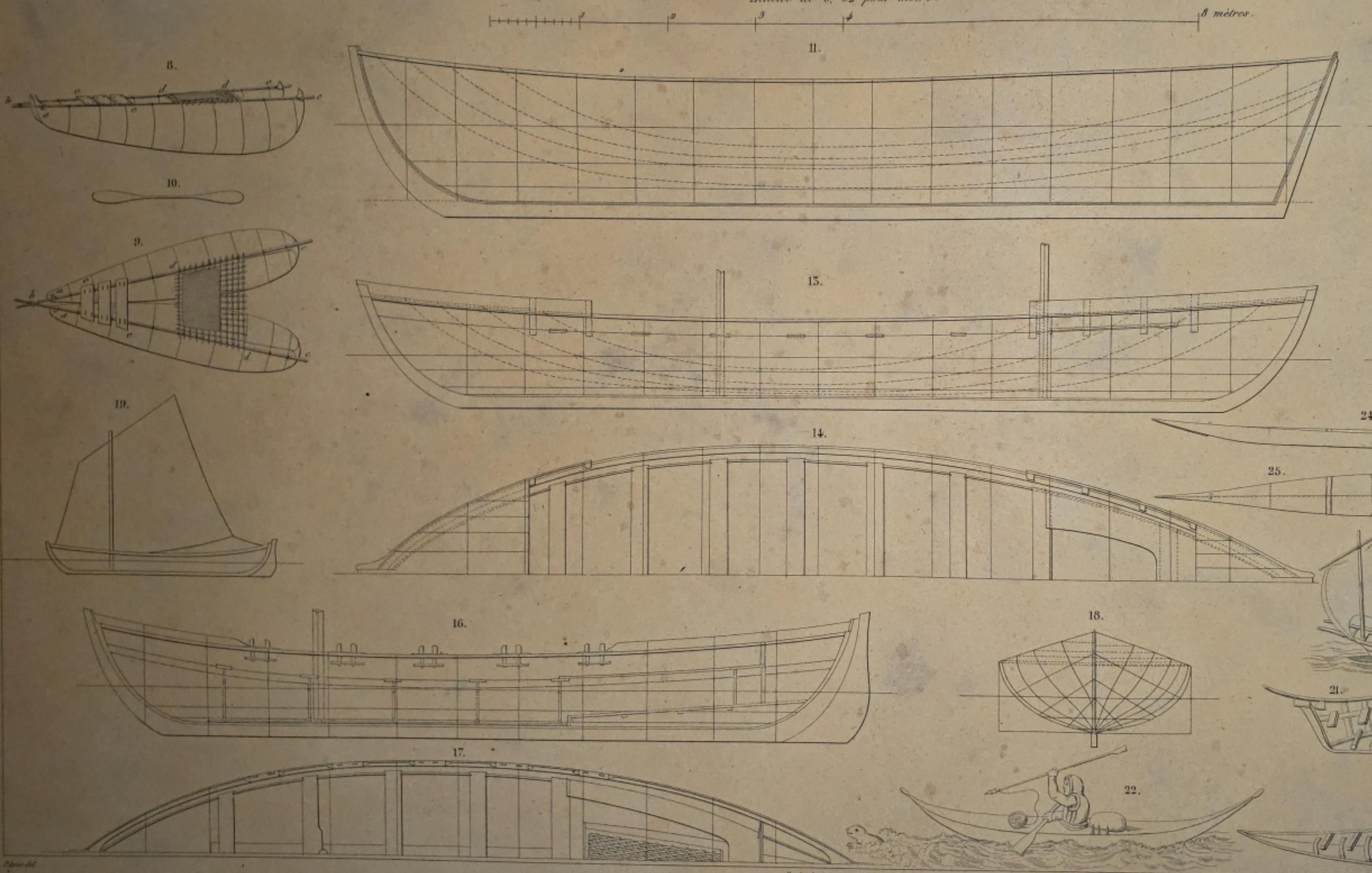
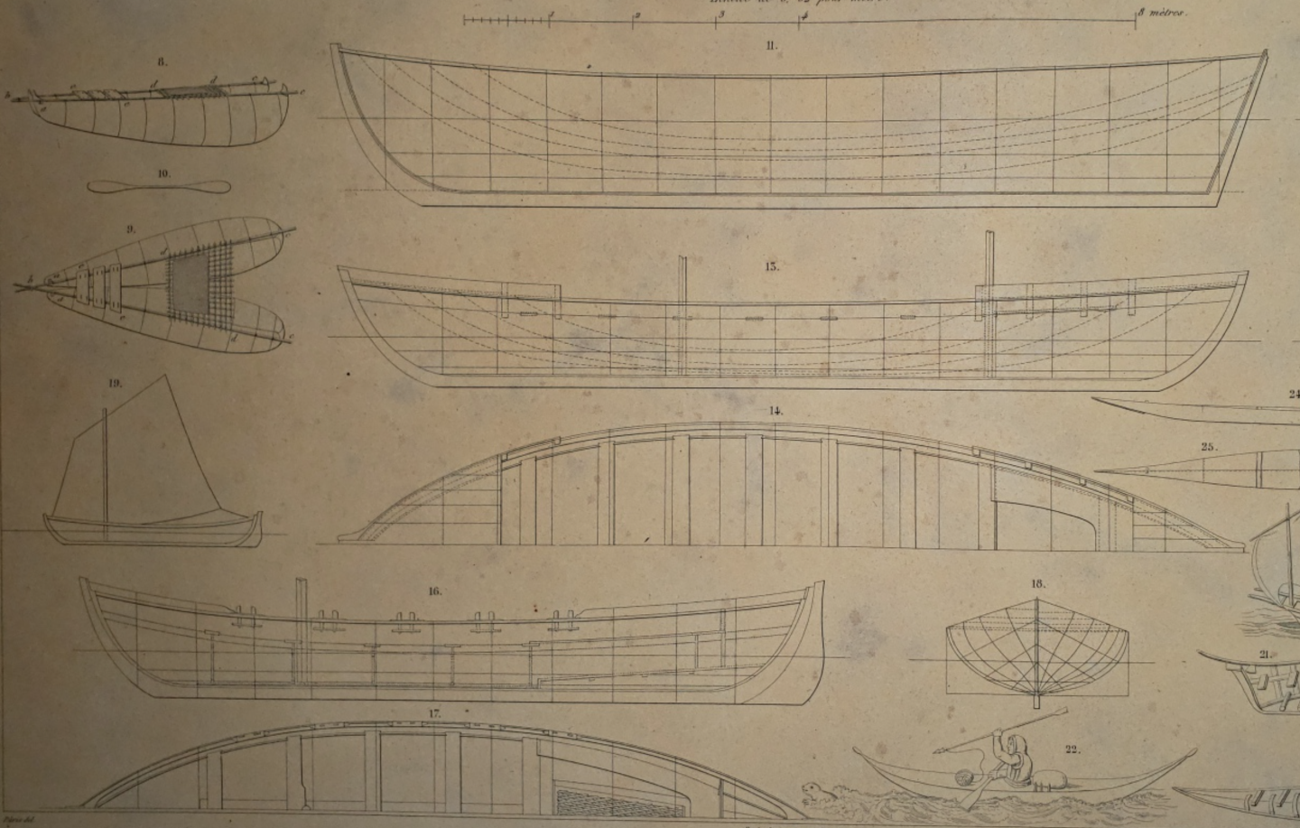
That's an excellent point, and in fact the whaleboat seems to have been a strong influence on Chilote vessels, although less the Lancha Chilota than other types. Whaleboats (and vessels derived from them) also were widely used elsewhere for coastal trade and fishing. They were used, and still are in use today, at Santa Catarina Island in Brazil for fishing, as described and extensively photographed in Joel Pacheco's A canoa baleeira dos Açores e da Ilha de Santa Catarina (Florianópolis, 2009). François-Edmond Pâris includes plan drawings of two "whaleboats" used for coastal trade in Montevideo, Uruguay, in his 1841 work Essai sur la construction navale des peuples extra-européens and briefly discusses their sailing qualities. (They're at center-right and bottom-left in the image below). In fact, the Musee de la Marine has a model of the two-masted whaleboat: https://mnm.webmuseo.com:8443/ws/musee-national-marine/app/collection/record/8909?vc=ePkH4LF7w6iejEyVcCaVlABg1YJaCRaW5meiVZdGFvC6F66eYJADAFHpLgQ$ There's definitely something to be said for the whaling industry as a factor in the global spread of certain vessel types and construction traditions.
- 312 replies
-
- 4
-
-
- Chile
- Latin America
- (and 6 more)
-
Definitely! I'll be discussing this in a future post, although unfortunately a lot of what I've been able to figure out about that aspect of the Lancha Chilota is still tentative (maybe Graham's book discusses it in more detail). But Latin America has been such a cross-roads historically that many of its workboats blend different boatbuilding traditions. For example, I haven't done much research on this yet, but the Saveiros of Bahia apparently draw not just on Iberian traditions, but also have some degree of Dutch influence from the period in the 17th Century when the Dutch controlled northeastern Brazil. (I also wouldn't be surprised if there was some degree of African influence as well, given that crews were often enslaved, former slaves, or their descendants, but I'd need to do more research first). And one of the very few Mexican workboats for which I've found plan drawings, the Laguna Madre Scow Sloop of Tamaulipas, is a variant of the fishing scows used along the Texas coast (pages 53-64 here: https://books.google.com.mx/books?id=W_7Ao0vWak4C&printsec=frontcover&redir_esc=y#v=onepage&q&f=true ) It's interesting to see that Chile seems to have only slowly moved away from wooden workboat. The Bongo Pesquero seems to have shifted to fiberglass construction in the 2000s, and wooden construction is apparently still common in southern Chile, although who knows how long that will continue.
- 312 replies
-
- 2
-
-
- Chile
- Latin America
- (and 6 more)
-
Thank you all for your interest! I should get to the build itself soon, there's just a bit I wanted to explain about the history/context first. Wefalck, I've definitely been surprised by how much information is available for these vessels and a few other types in Latin America. The lancha chilota, along with the Brazilian saveiro and jangada, the Peruvian caballito de totora, and a few other types of workboats, seems to have been canonized as a vital aspect of regional heritage and has received a lot of attention. This is great for modeling, but a lot of other types that were historically important have been basically ignored. In photo archives, I've come across images of a number of vessel types (such as the double-ended open boats used for fishing in Veracruz) that seem regionally distinctive and socially/economically important but that have very little if anything written about them. And that's not to mention the many vessels that were never photographed. It's very interesting to consider how and why some types of boats get remembered and others don't. I'm surprised that more hasn't been written about Baltic traders, for instance, and am very much looking forward to following your Rahschlup build. Also, while the national Maritime Museum in Valparaiso does seem to be pretty focused on naval ships, some smaller museums seem to do a lot more with workboats, like the Museo Regional de Ancud on Chiloé Island.
- 312 replies
-
- 4
-
-
- Chile
- Latin America
- (and 6 more)
-
Nice start, I'm looking forward to following along on this build!
- 28 replies
-
- 2
-
-
- Lowell Grand Banks Dory
- Model Shipways
- (and 1 more)
-
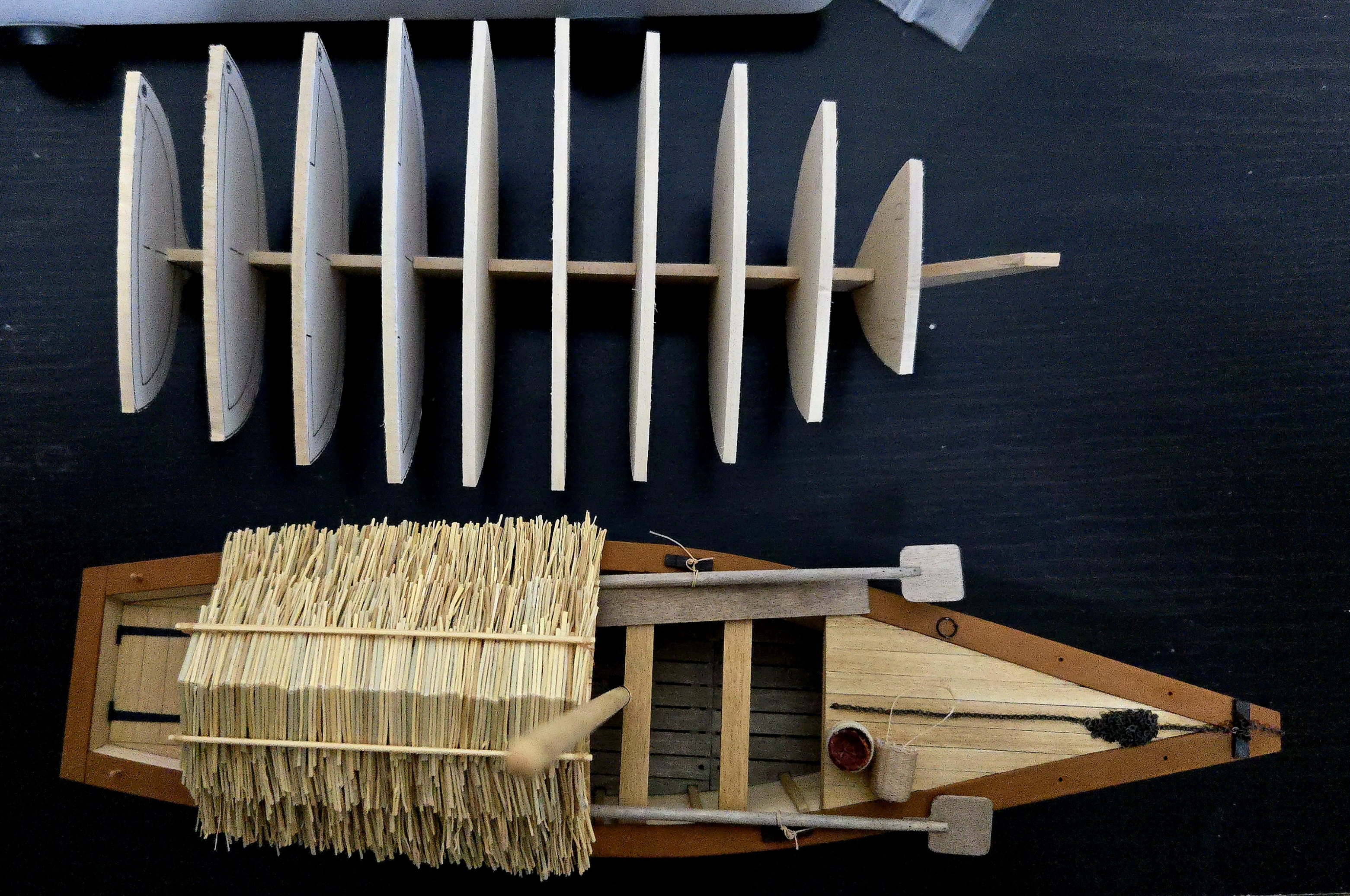
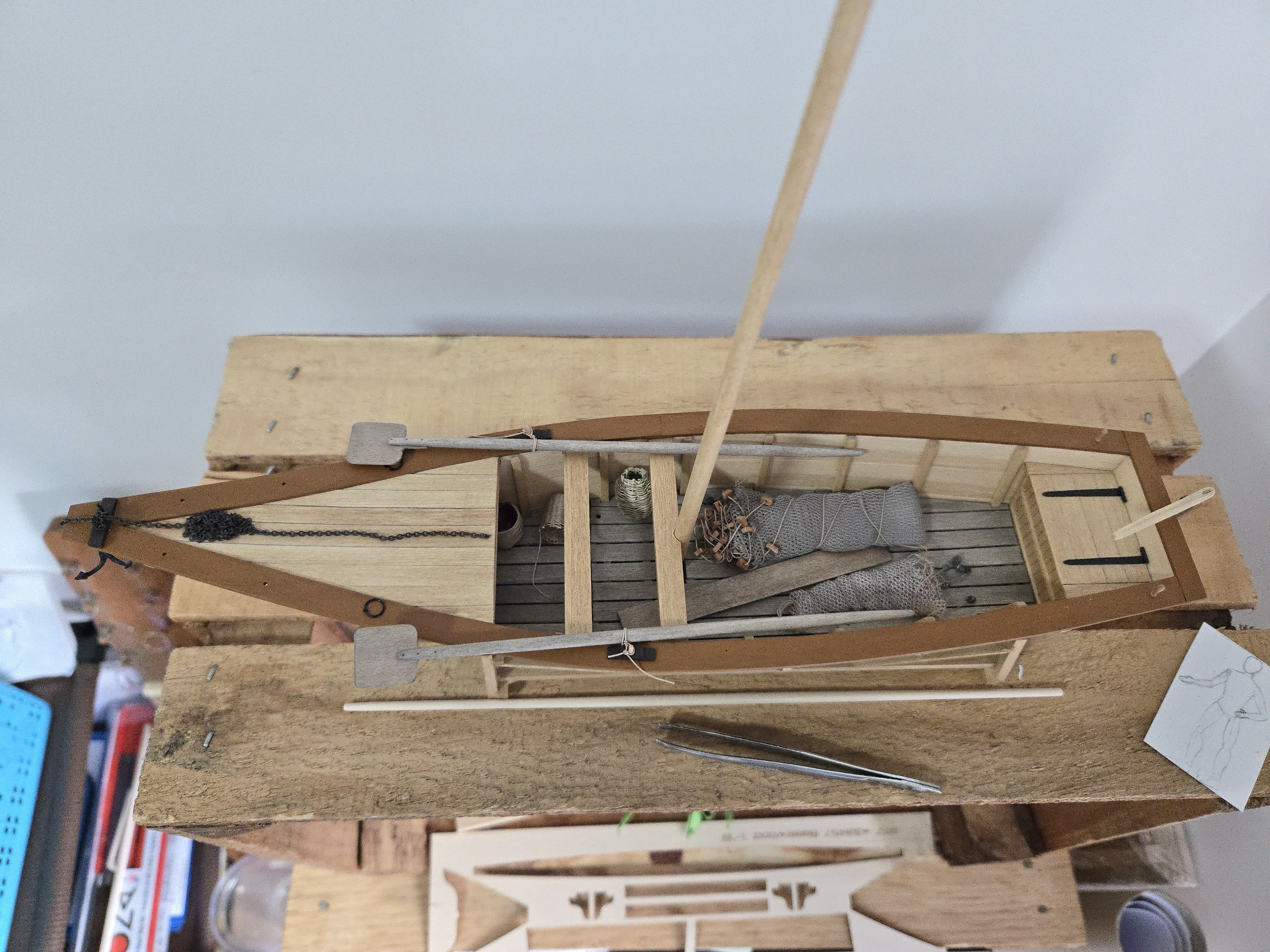
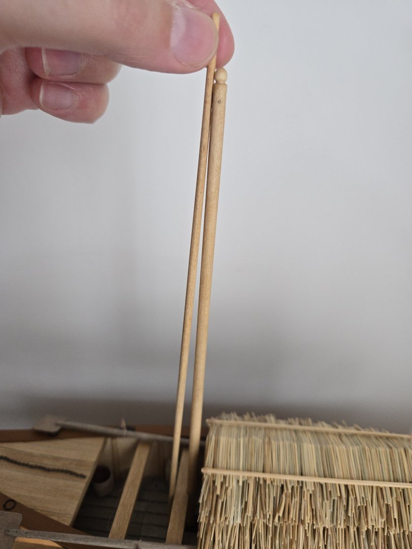
Still trying to figure out the sail material. On the other hand, I think I have the yard finished. I was able to most sand off the reddish stain, although some did stick to parts of the grain. I then added a very heavily thinned layer of gray stain (along the way managing to spill turpentine all over the office--quite a pain to clean up, I will definitely try sticking to stain pens in the future). As can be seen below, the yard looks pretty close to the mast color now: There are still some slight differences, but at least some of it is because the mast and yard are made of different materials that seem to have taken up the stain slightly differently. The mast came from a dowel, presumably birch, while the yard is basswood. The yard looks like a pretty good match for the basswood deck planks, which received the same stain as the mast. So, all I have to do by now is to glue the furnishings in place, make the sail, and attach the (very simple) rigging. In any case, I recently received some very welcome news back on a job application, so I'll be staying in Mexico for at least the next year abd a half. To celebrate, I figured I would start my next build log, for a Chilean coastal sloop (lancha chilota, link in signature). Given that material issues have held up the canoa for now, I don't think a new build will interfere with finishing this one, and I'd already made some progress. Size comparison between the Canoa and the Lancha's skeleton, below:


-
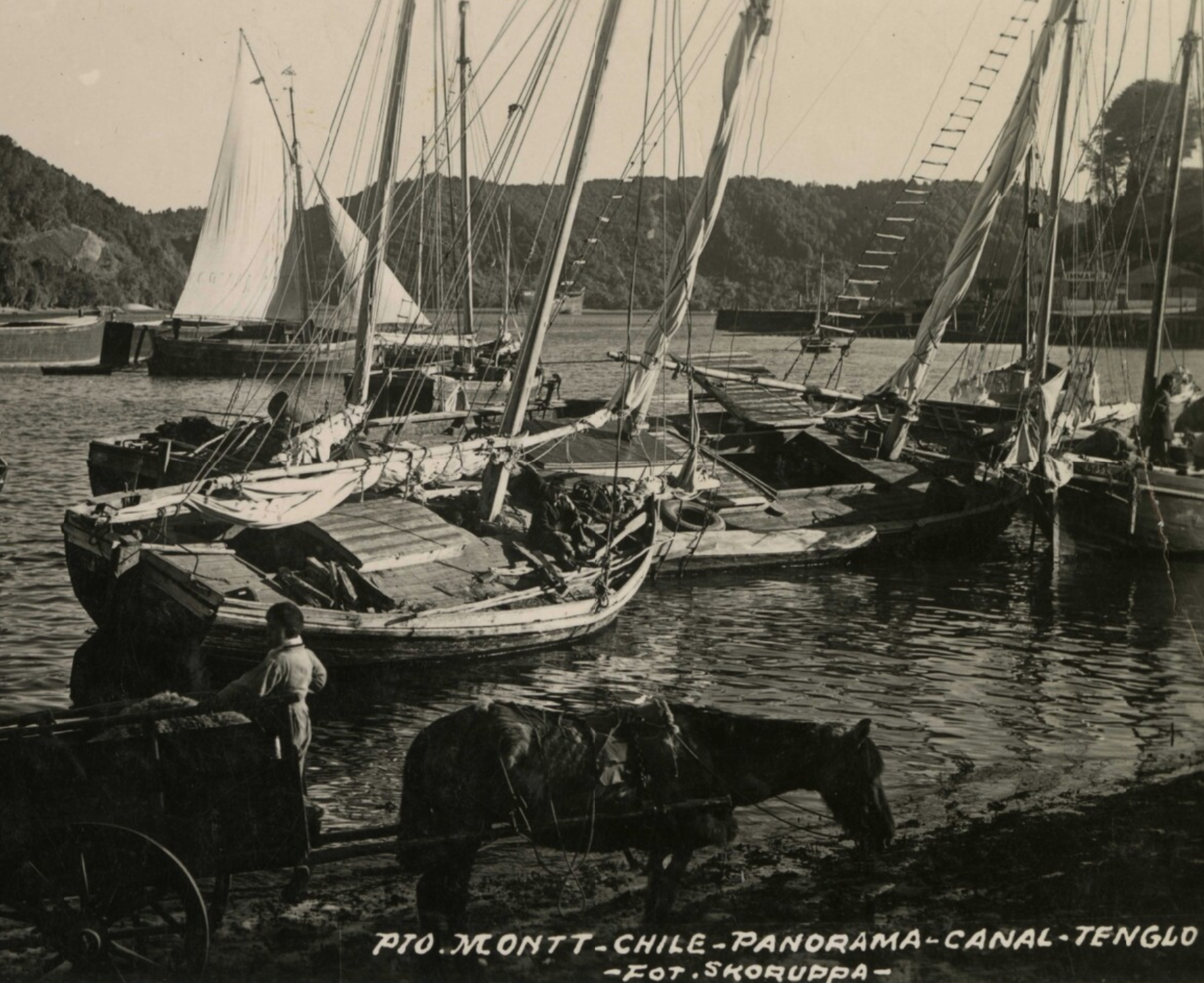
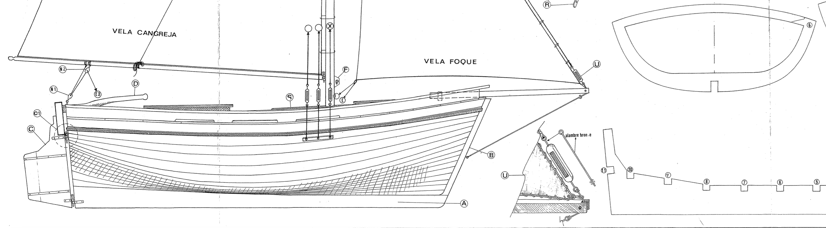
Sources There are quite a few sources on lanchas chilotas and the Chiloé Archipelago’s maritime history more generally, in part because the vessels have increasingly been promoted as an element of regional culture, leading to various state and private initiatives to preserve construction techniques and memory of these vessels. The most comprehensive source would appear to be José A. Garnham's Lanchas Chilotas: un patrimonio histórico y cultural de Chile (Chile: Editorial Ricaventura, 2017). Garnham, who has some maritime heritage preservation experience, apparently based much of the book on extensive interviews with surviving lancha builders and sailors, and the book includes in-depth profiles of a number of vessels along with more general information. Unfortunately, I have been entirely unable to get my hands on a copy. It's sold out on every online store, and my interlibrary loan request was unsuccessful. The book's website is still up ( http://lanchaschilotas.com/lanchas-chilotas-un-patrimonio-historico-y-cultural-de-chile/ ), but hasn't been updated since 2019, and my attempts to email the author directly haven't met with a response. Thankfully, there are a lot of other sources. Even without Garnham’s book, his website (linked in the previous paragraph) has a lot of useful information and photographs on the type’s history and construction. There are a number of other blog posts and the like that explore the lancha chilota, too, such as this one: https://filanaval.blogspot.com/2010/09/lanchas-chilotas.html?m=1 Several published books also discuss the lancha chilota in more or less detail. In English, one chapter of The Last Sailors: The Final Days of Working Sail by Neil Hollander and Harald Mertes (London: Angus and Robertson, 1984) presents an ethnographic look at some of the last working lanchas in the 1970s. Besides including photos, it describes in great detail the difficult lives of the lancha sailors. Notably, they seem to have no romantic ideas about the vessels, and are quite happy to get rid of them as soon as easier ways of making a living emerge. The book was also made into a documentary narrated by a late-career Orson Welles, which I have yet to watch. In the extended trailer on YouTube, a lancha chilota briefly appears in color at 2:14 ( https://m.youtube.com/watch?v=Y4U5lway2Uw Another book that’s worth noting is Anton Daughters’ Memories of Earth and Sea: An Ethnographic History of the Islands of Chiloé (Tucson: University of Arizona Press, 2019). It says next to nothing about the lancha chilota itself, just briefly remarking that local sailboat designs fully replaced earlier sewn-plank dalcas by the first decades of the twentieth century (p. 46-47). However, it’s an invaluable source on the archipelago’s history and society, giving a very clear sense of how the sea strongly shaped Chiloé society, and also of the importance of memory and ideas of tradition in Chiloé today, especially as islanders frustrated by the pisciculture economy draw on the past as a source of inspiration and solidarity as they seek to chart a course forward. The book is therefore useful for helping to contextualize the recent resurgence of regional interest in preserving the lancha chilota. The book Chiloé, a compilation of various essays put together by the Museo Chileno de Arte Precolombino and Banco Santander, also includes some interesting introductory information and a lot of excellent color photographs of the island and its inhabitants today (it’s available for free download from the Museum, link at the following site: https://www.centroculturalcastro.cl/inicio/2016/chiloe/ ). The sections on navigation and boatbuilding today are particularly interesting. There are quite a few resources on heritage, preservation, and on present-day lanchas (which, I should note, seem to frequently be built with much more extensive cabins than the original vessels) as well as on their history. To name just a few that are useful, the booklet Rutas y historias de la navegación a vela was published by the Cofradía del Navegante Chilote in 2022. It includes a lot of photos, and is available digitally here: https://issuu.com/cofradianavegantes/docs/libro_navegante_chilote . The following article at La Tercera from 2015 also discusses lanchas chilotas and their history in the wake of UNESCO having named two lancha builders as Living Human Treasures. It further talks about the various regattas and heritage preservation events surrounding the vessels: https://www.latercera.com/paula/aprendices-de-chilote/ There are also a lot of interesting videos on YouTube documenting the lancha chilota, the revival of interest in it, and lancha models (which were historically used in lieu of plans to develop hull forms). The Museo de Veleras Chilotas—a small but fascinating-looking museum dedicated to Chiloé’s diverse sailing vessels—is featured in several videos, discussing lancha construction and sailing with the aid of models and a full-size lancha that was built there. See, for instance: https://m.youtube.com/watch?v=0nKbcKac0Wk and https://m.youtube.com/watch?v=lgkMlx0jRBI . Another Chilean news channel also interviewed a traditional lancha model builder: https://m.youtube.com/watch?v=S_tKWwSgwpo . Finally, there’s some information on lanchas, as well as some other Chilean vessels, at this site run by a Chilean ship modeler: https://losbarcosdejuanvasquez.wordpress.com/ These sources can tell a lot about the broader cultural meaning assigned to the lancha chilota. More prosaically, they’re also helpful sources for figuring out details of the vessel’s construction that will be helpful for model-building. Of course, caution is necessary when taking images and writings about present-day vessels and applying them to boats used in the past. Photos from the lancha chilota’s heyday are therefore extremely useful sources, as they can shed light on details that may have changed over time—especially as present-day lanchas are generally have more standardized fittings and are different in other details from the working vessels of the past. Fortunately, there are quite a few photos of lanchas in the late nineteenth through the mid-twentieth century (especially from the 1950s-1960s) that are available digitally through the Chilean National Digital Library. (Link: https://www.bibliotecanacionaldigital.gob.cl/bnd/612/w3-channel.html ). I haven’t found as many photos as I did for the Canoa de Rancho build, but I suppose it makes sense that the working ports around Chiloé would attract less photographic attention than Lake Chapala, which was a major tourist destination beginning in the late 1800s. Searching for keywords like “lancha,” “embarcación,” or “Puerto Montt” brings up photo after photo, often with quite detailed contextual information in the written description. In this detail from a larger photo, we can see a number of lanchas—including a larger two-masted lancha—beached at Puerto Montt in 1953 for cargo handling. Source: Pto. Montt - Chile - Panorama - Canal-Tenglo. 1953. Photographer: Studio of Arnaldo Skoruppa (1910-1983). Available in: Archivo Fotográfico, Biblioteca Nacional Digital de Chile. https://www.bibliotecanacionaldigital.gob.cl/bnd/629/w3-article-613545.html Finally, I also have a set of modeling plans. This site ( https://filanaval.blogspot.com/2010/09/lanchas-chilotas.html?m=1 ) included a link allowing visitors to download a set of plans from the Club de Modelismo Naval Santiago—a Santiago-based boat modeling club that has used the lancha chilota as its symbol for decades. The link was dead, so I reached out to the club directly via their Facebook page. They very kindly shared the set of plans (and would presumably be willing to do so if anyone else wants the plans). It's a large single sheet drawing that includes bulkhead and keel shapes, deck plan, sail and rigging plan, and details of the anchor and other fittings. I include a sample below showing a side view of the hull, a detail of the tip of the bowsprit and rigging, and a bulkhead and part of the false keel. As I’ll discuss later, I’m modifying the plans in several ways, but they are an absolutely invaluable source, and I would not be able to do this build without them. The plan set is based (although isn’t an exact copy, at least in several details) on the Quenita I, a lancha which Garnham photographed extensively and which sank at its moorings in the early 2000s after falling into disrepair. The Quenita I is shown below: Source: http://lanchaschilotas.com/dscn7150-2/ Put together, these sources provide me with a useful basis for modeling a lancha chilota. I have a lot more historical and construction information on this type than I did for the Canoa de Rancho, which is a welcome change in many ways. This is already a long post, so I’ll get into the history and context (and, finally, the build itself) in the next posts.


- 312 replies
-
- 11
-
-
- Chile
- Latin America
- (and 6 more)
-
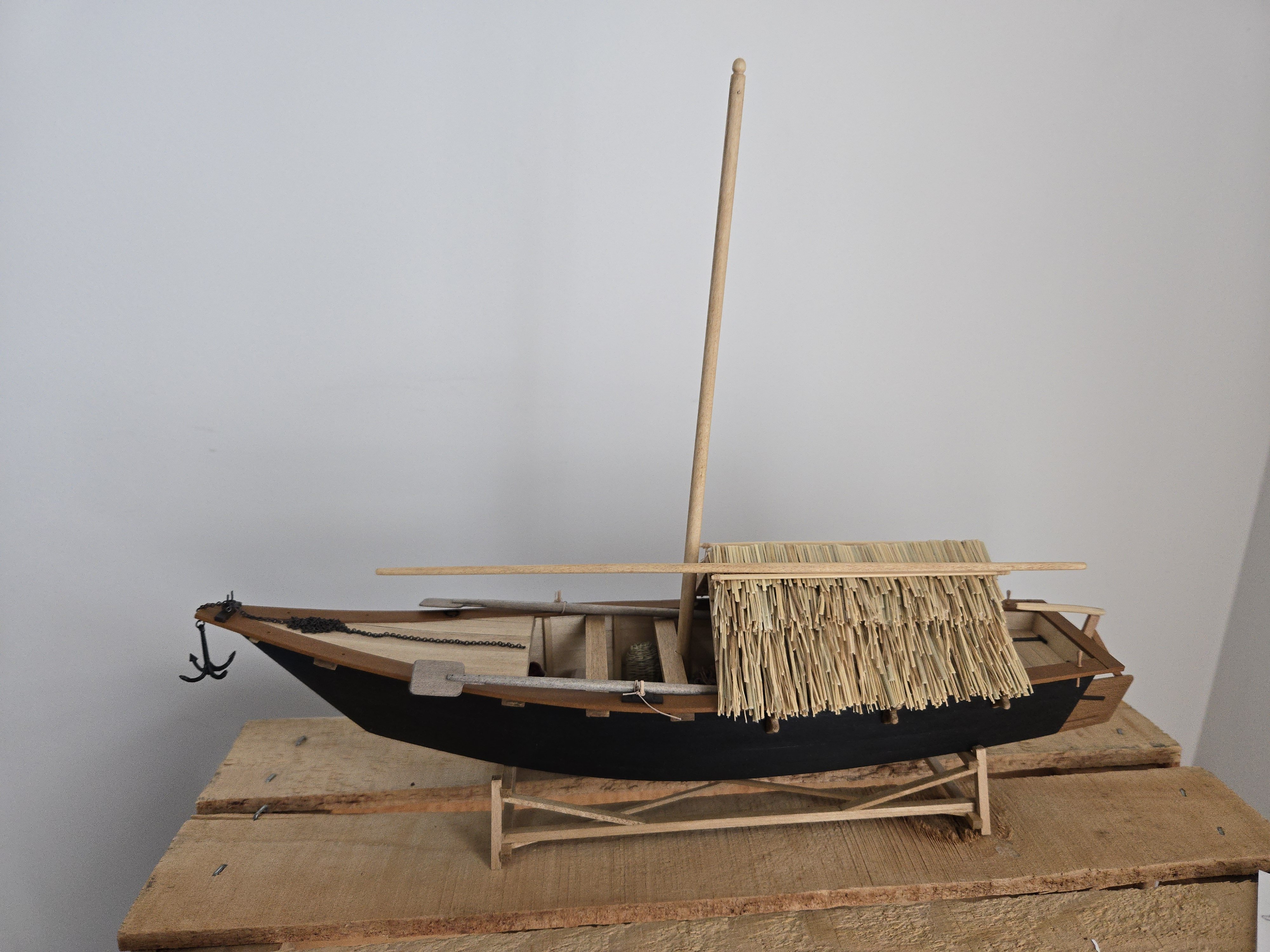
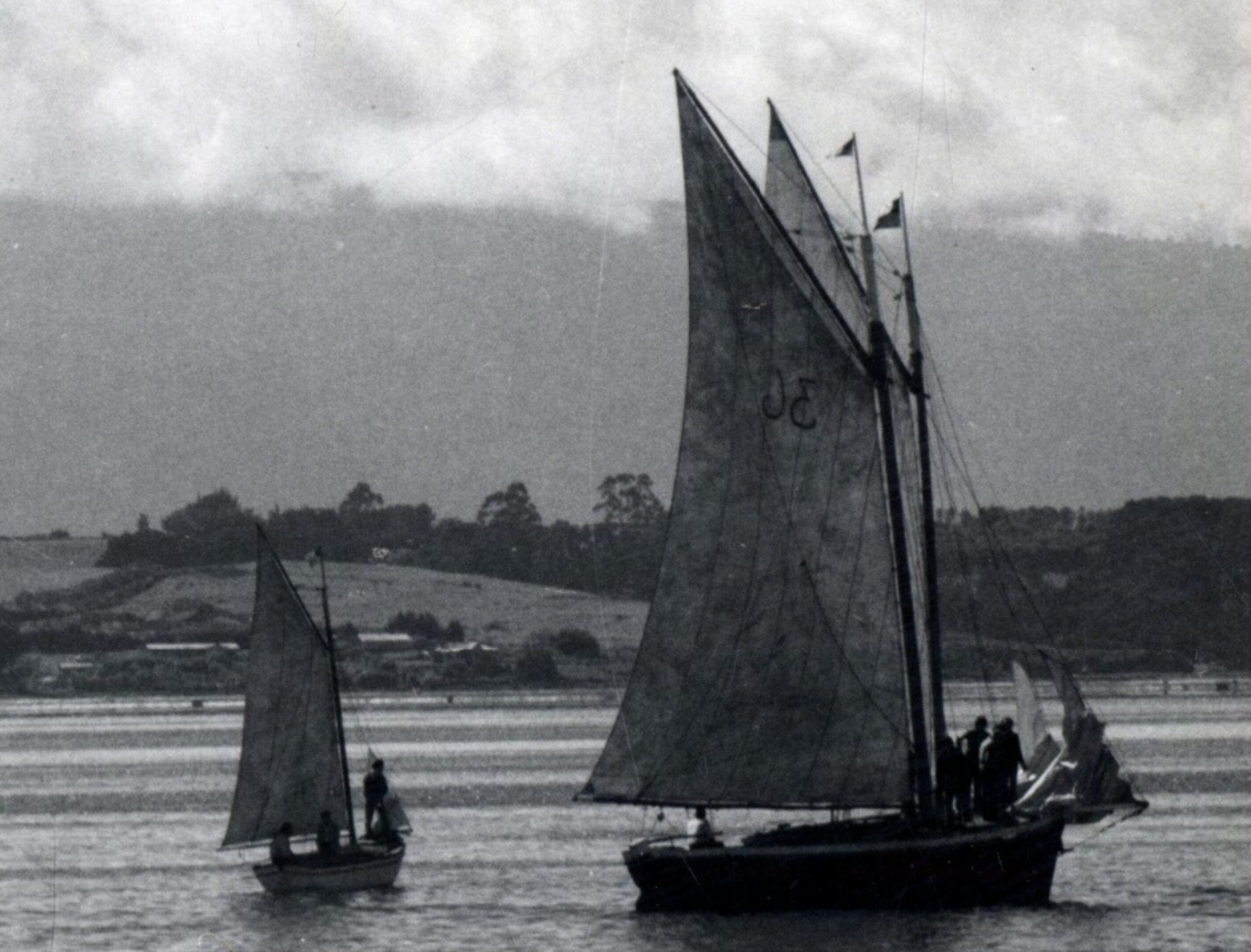
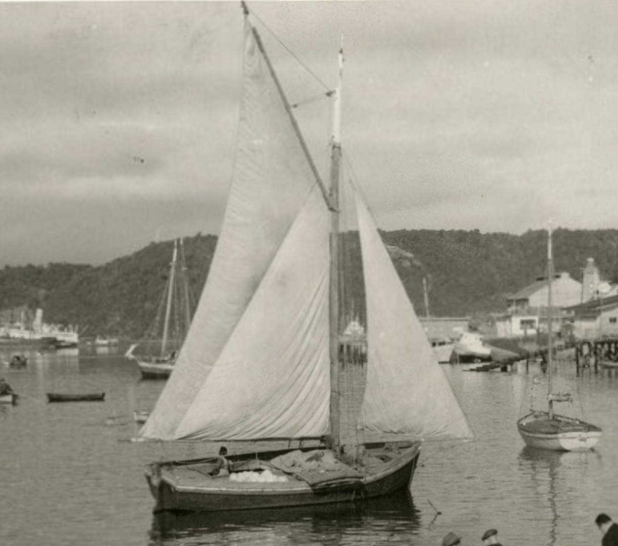
Following up on my Trajinera and Canoa de Rancho builds (the latter of which should be finished in the next weeks once I find an appropriate material for the furled sail), I've embarked on yet another scratch build of a "traditional" Latin American workboat. This time, I'm leaving behind the lakes and canals of Central Mexico to head to the rugged, windswept coast of southern Chile. I'll be modeling a Lancha Chilota, seen below, a small coasting sloop developed and used in and around the Chiloé Archipelago from the late nineteenth century up until its replacement with powered vessels in the second half of the twentieth century. Source: Caleta Angelmó, Pto. Montt, Chile. 1966. Photographer: Kurt Grassau (1930-). Available in: Archivo Fotográfico, Biblioteca Nacional Digital de Chile. https://www.bibliotecanacionaldigital.gob.cl/bnd/635/w3-article-613547.html This will be my first plank-on-bulkhead build, my first fully-decked build, and the most complex rigging I've yet made (although it's still quite simple, all things considered). I’ve already started and have made progress on the internal framework. I'm looking forward to further developing my skills, and to recreating in miniature another aspect of Latin America's maritime history. A word of warning: it will be a few posts before I get to the build itself. I’ll first be discussing my rationale behind choosing this subject, available sources, and a bit about the history and context of the lancha chilota. I’ll also be briefly touching on some other types of Chilean workboats along the way. Why the Lancha Chilota? So, why did I choose this subject? There are a few reasons. Most broadly, I think that vernacular watercraft—the term preferred by maritime archeologists for "traditional" boats, as the word "traditional" implies that these vessels are ancient and unchanging, when they’re usually anything but that—are often unheralded build subjects. This is especially the case for Latin America. Workboats are interesting subjects not only because the technology and building methods involved showcase histories of local innovations and wider influences, but also because they can shed light on broader questions about societies, economies, and cultures. Workboats develop out of economic imperative and draw on at times quite divergent traditions of craftsmanship and design. They can tell us something about how people relate to their means of laboring for their subsistence, and can take on wider meanings as cultural symbols. These are all interesting issues, and a model can serve as a starting point for considering them, even if a model in itself probably won’t fully answer any of them. By building Latin American workboats, I hope to show that these vessels are interesting and worthwhile subjects, and that modeling them can help us see ways of thinking more broadly about Latin American societies and cultures. More specifically, I knew that I wanted to make a Chilean vessel because a study abroad session in Chile is what really set off my interest in Latin America. Regretfully, I didn't spend as much time as I would have liked on the coast and I never made it as far south as Chiloé, as I was a broke college student. I did, however, visit Valparaiso and its excellent naval museum, the Museo Marítimo Nacional (which @Cathead wrote an excellent post about—in fact, his whole post is quite interesting and informative, covering much more about coastal Chile and its maritime heritage, including Puerto Montt, an important port for lanchas chilotas. I highly recommend checking it out: https://modelshipworld.com/topic/19664-exploring-the-maritime-history-and-geography-of-chile/#comment-599913 ). While there, I was struck by the degree to which Chile as a whole seemed a society strongly shaped by its relationship with the sea. You can see this everywhere from the nationalist celebrations of naval heroes like Thomas Cochrane and Arturo Prat, to the more quotidian importance of seafood and its production in Chilean culture and economy. There's a huge variety of Chilean vernacular watercraft, ranging from sewn plank canoes (dalcas), to inflated hide rafts, to various wooden coasting vessels. All of them would make fascinating build subjects, and I seriously considered several options. A Bongo Pesquero open fishing boat had the advantage of being something I had seen in person at the naval museum in Valparaiso (as seen below). Notably, the museum’s vessel, which was built in 1990 and retired in 2009, is the only surviving wooden bongo, as they were traditionally burned at the end of their time in use. But the only plans I could find were for the fiberglass vessels that recently replaced the wooden ones, which have quite different hull shapes. Source: Personal photo. Another option, the Falucho Maulino coastal trader (below, also called a Lanchón Maulino) had the advantage of being extremely distinctive and culturally significant. However, not only is it a bit too large to work at my preferred scale (at least until I have more space), but it has a complex hull framing that would be largely exposed (as it's undecked) that would be a stretch for my current skills. Most importantly, I couldn't find any plans (although there are apparently some reconstruction efforts, and it may just be a matter of contacting the right people—this may be a topic I explore in the future). Source: Lanchón maulino navegando al norte. 1959. Photographer: Domingo Ulloa (1925-2018). Available in: Archivo Fotográfico, Biblioteca Nacional Digital de Chile. https://www.bibliotecanacionaldigital.gob.cl/bnd/635/w3-article-164498.html Ultimately, the Lancha Chilota checked off everything I was looking for in a build. It's a distinctive and culturally significant vessel. The hull structure, which is completely decked besides some hatches, lends itself to plank-on-bulkhead construction, which I'd like to get experience with, and its rigging will help me develop skills without being too complex. It's a good size for 1:32 scale, with the model hull less than a foot long. Finally, as I'll discuss below, I was able to find quite a few written and visual sources and, crucially, obtain a set of plans, so there will be much less guesswork involved on basic questions (like hull proportions) than I experienced in my Canoa de Rancho and Trajinera builds. Below: Lanchas Chilotas near Puerto Montt, image published 1959. Source: Lanchas chilotas cerca de Puerto Montt. 1959. Photographer: Domingo Ulloa (1925-2018). Available in: Archivo Fotográfico, Biblioteca Nacional Digital de Chile. https://www.bibliotecanacionaldigital.gob.cl/bnd/635/w3-article-164286.html I actually began this build early this year while I was still in Chicago. However, I realized after cutting out many of the internal structural parts that I wouldn’t have the time for this build as well as all my others going on at the same time, and that I would need to build skills in things like planking before I could really proceed. I also didn’t start the build log yet because I was still holding out hope that I would get my hands on an apparently vital book that would allow me to do a much better job introducing the boat. Although I wasn’t able to get the book, I finally reached a point where I felt comfortable starting the build log and really getting into the work on the model. Also, there are a few things I have questions about that I want to ask before I go further. This post is already a bit long, so I’ll stop it here. Next, I’ll get into sources.

- 312 replies
-
- 12
-
-
- Chile
- Latin America
- (and 6 more)
-
Nice job working around some of the kit's limitations!
- 86 replies
-
- 1
-
-
- San Francisco
- Artesania Latina
- (and 2 more)
-
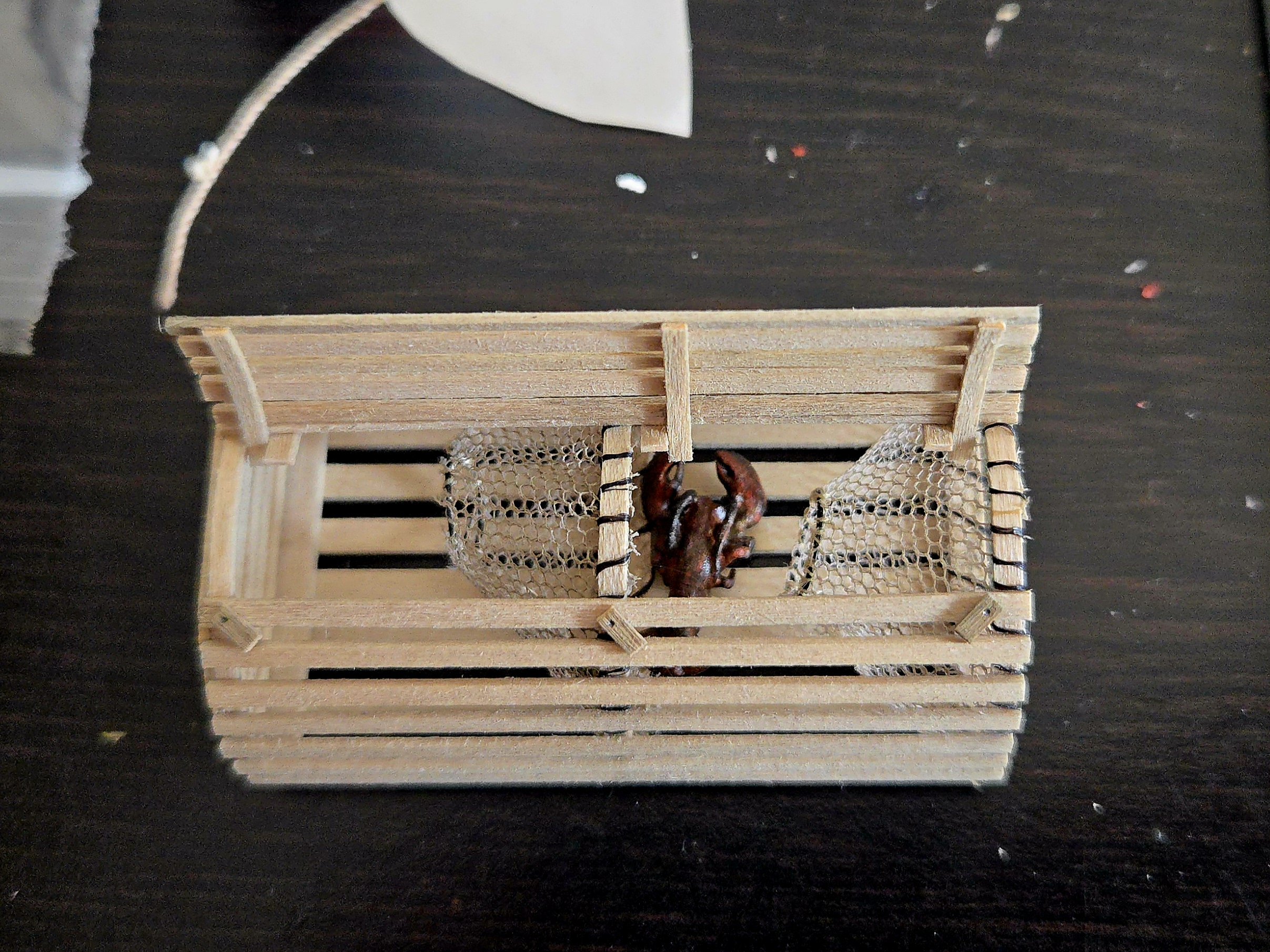
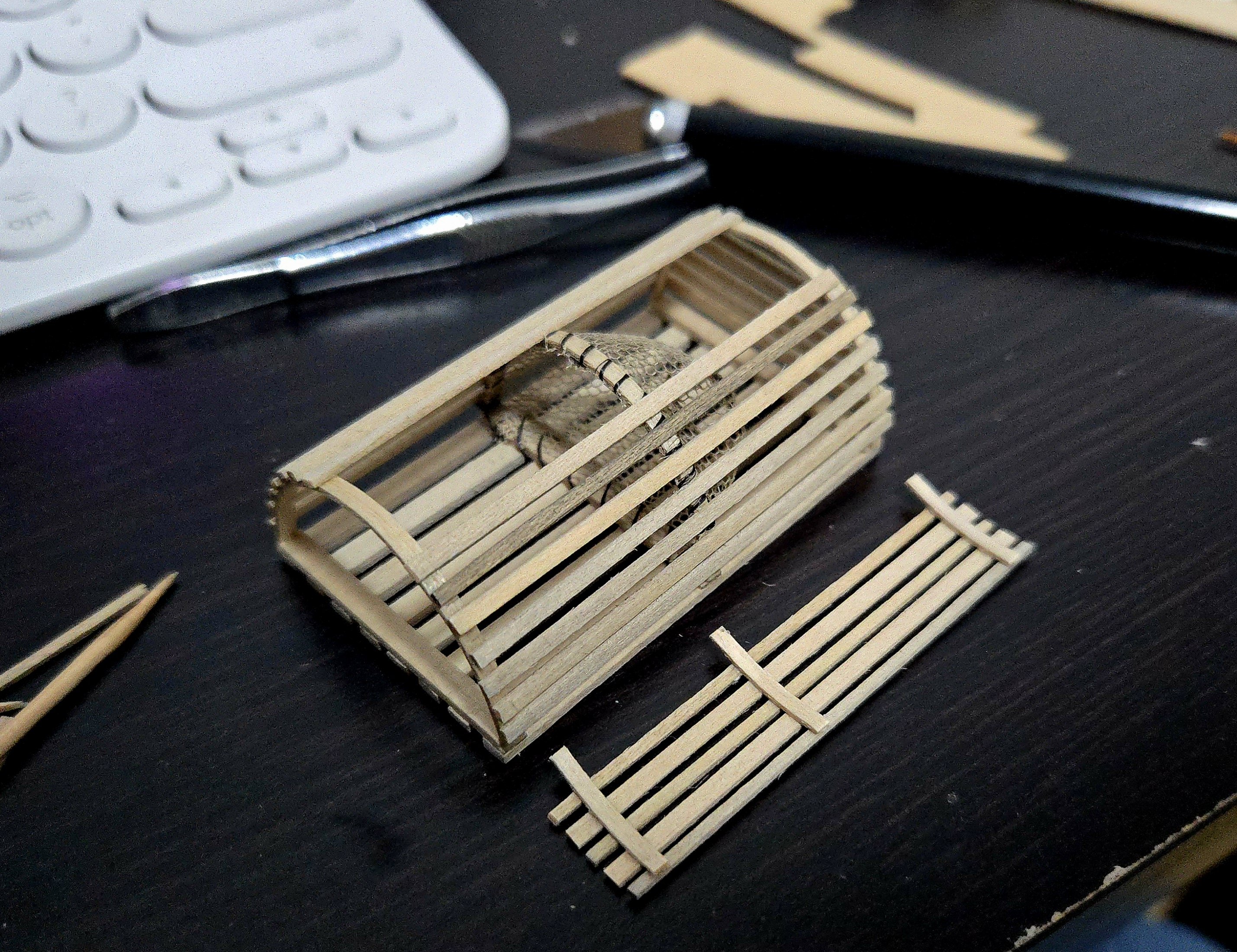
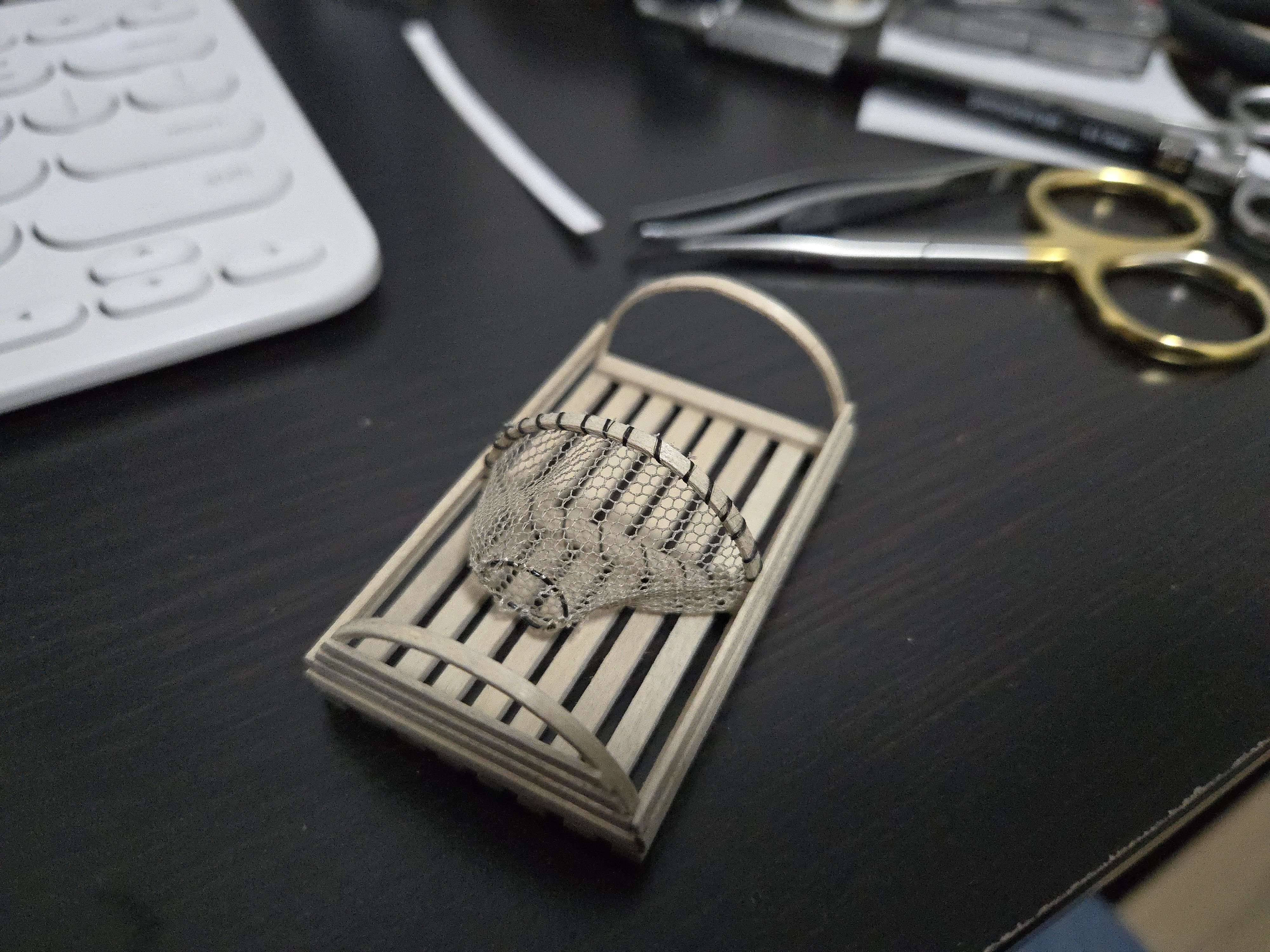
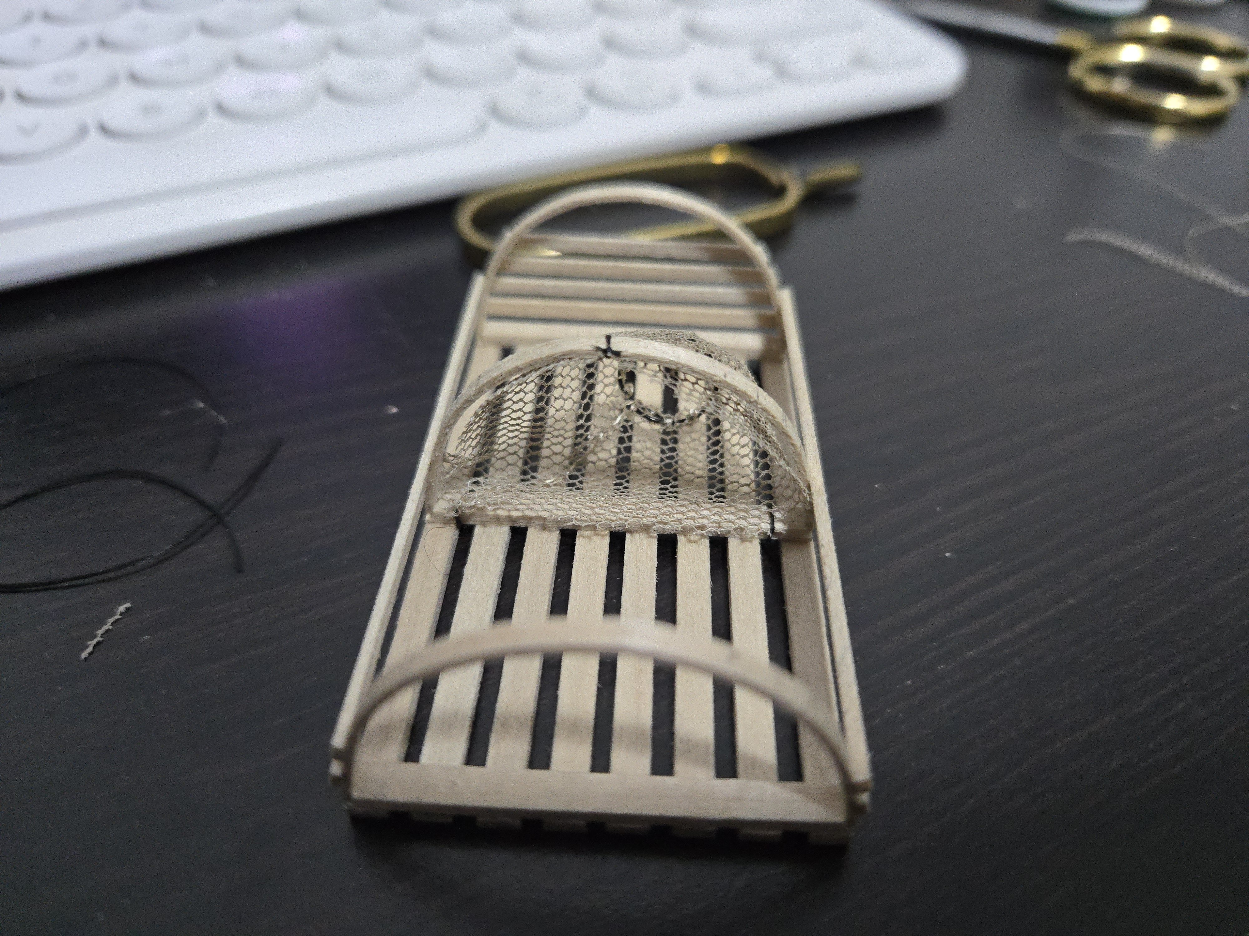
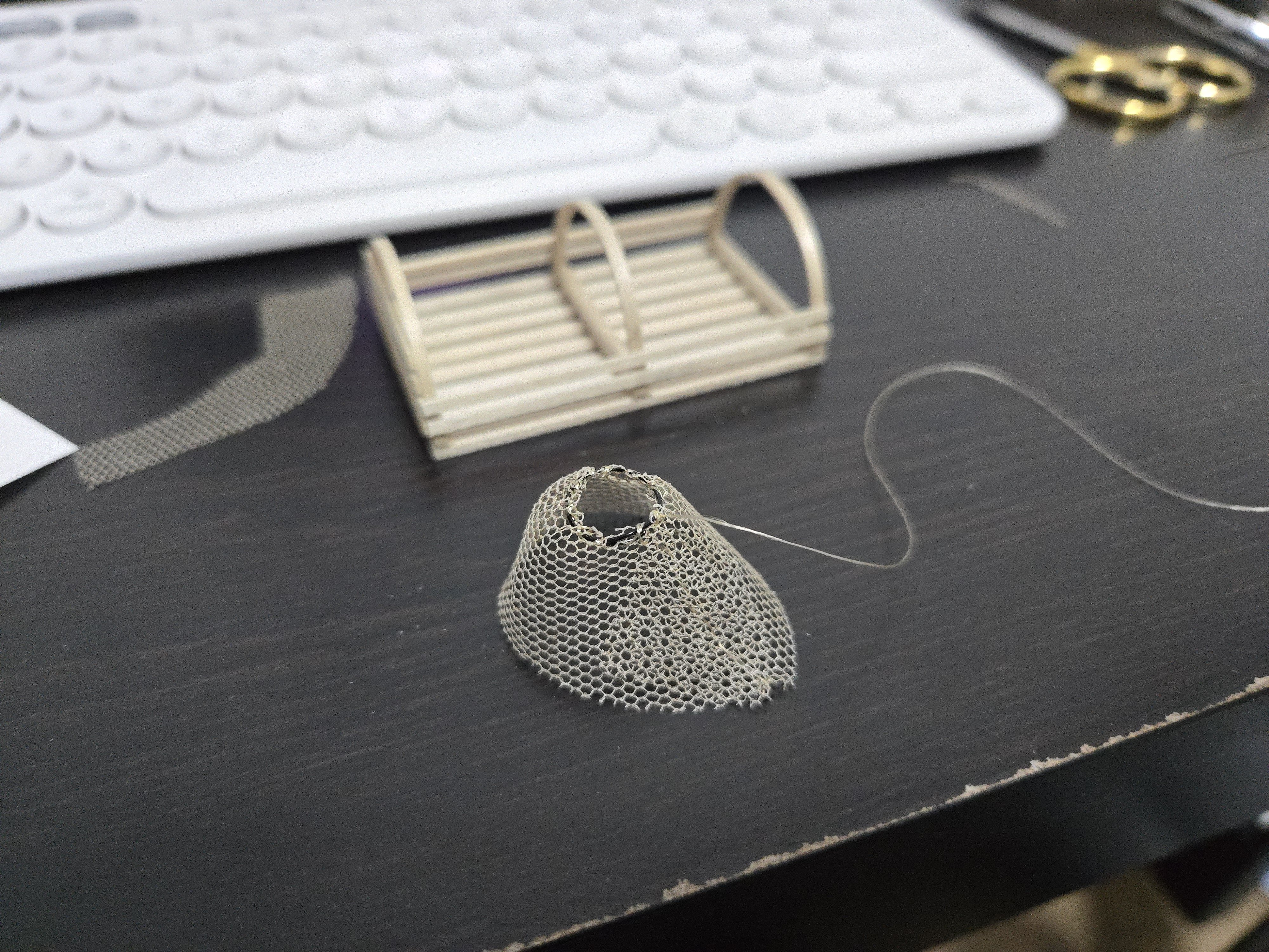
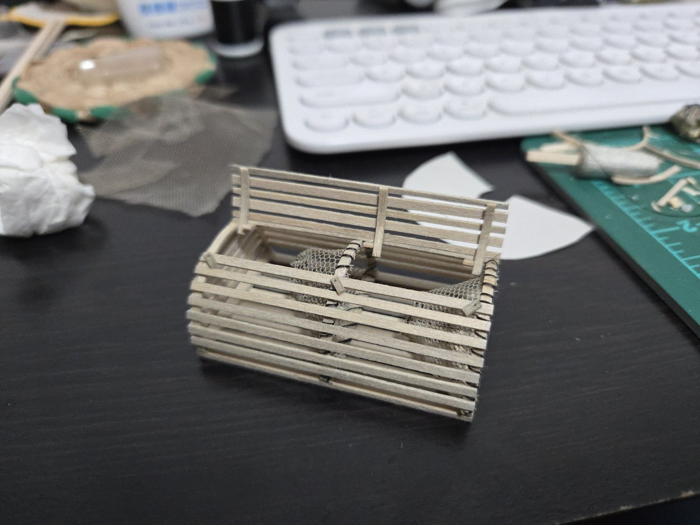
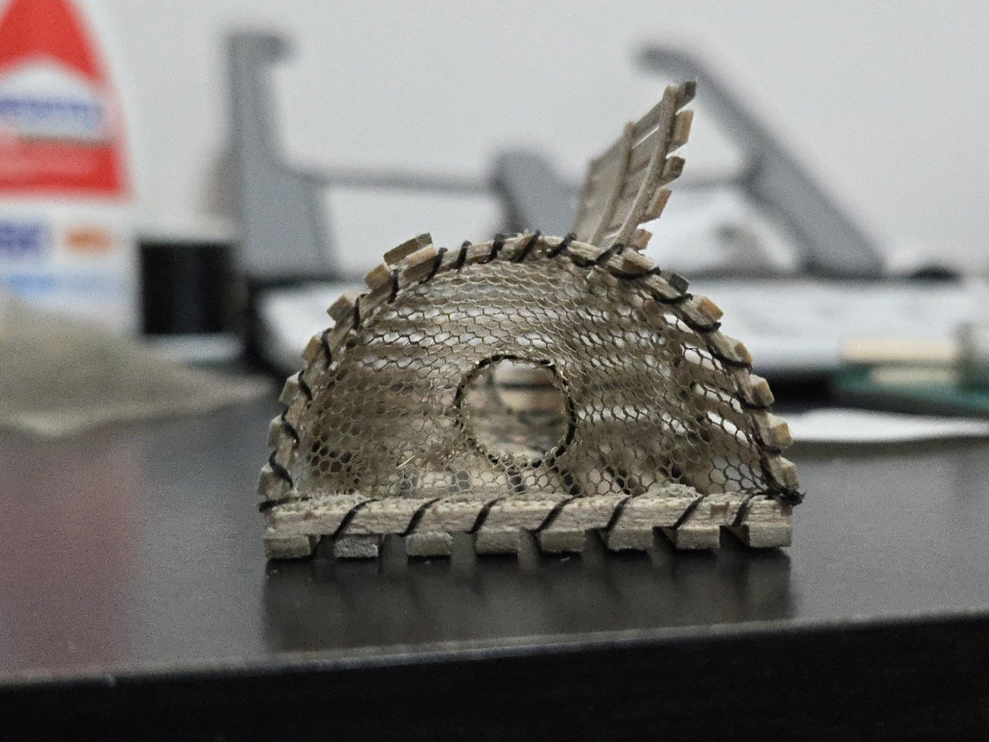
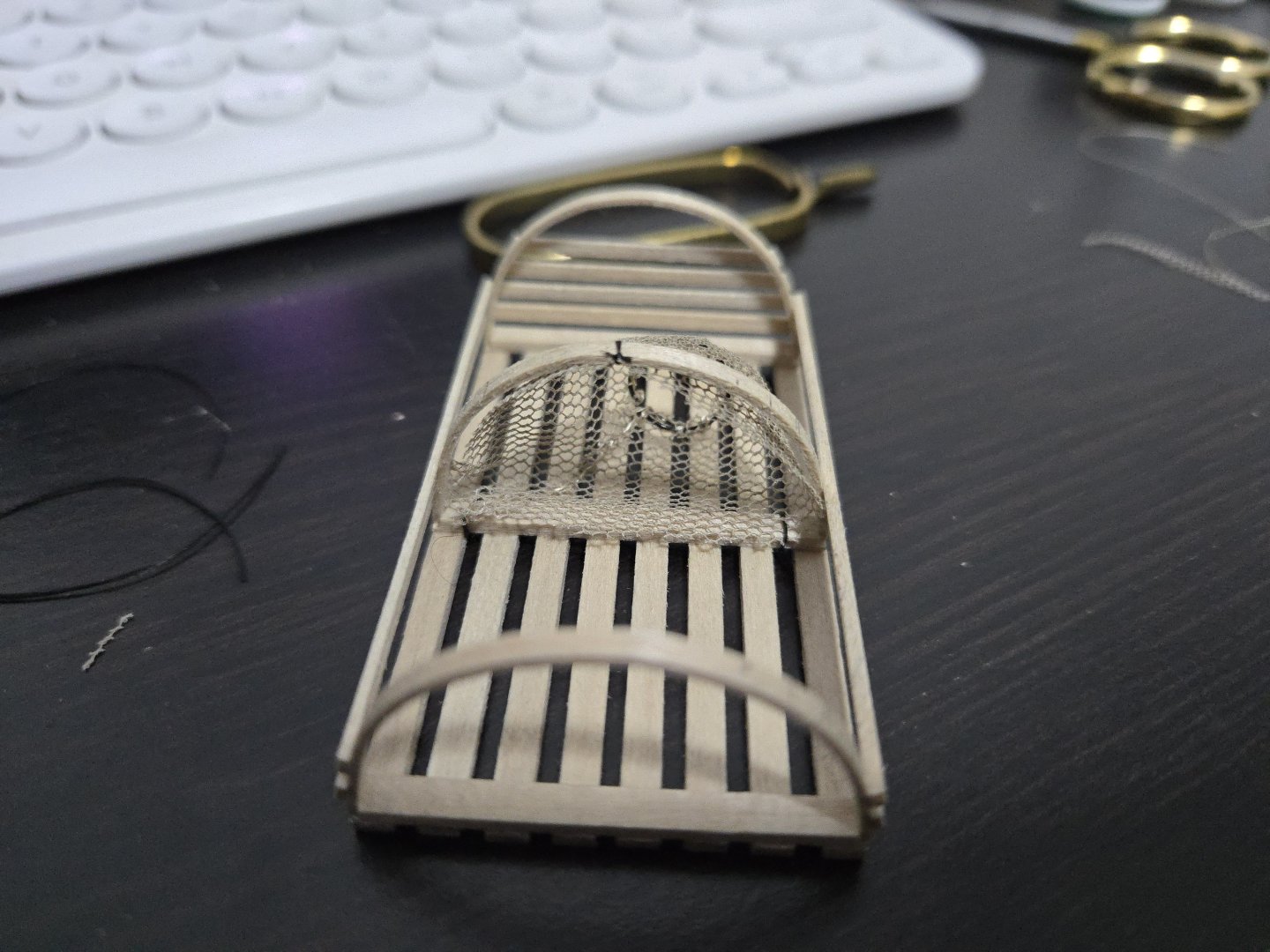
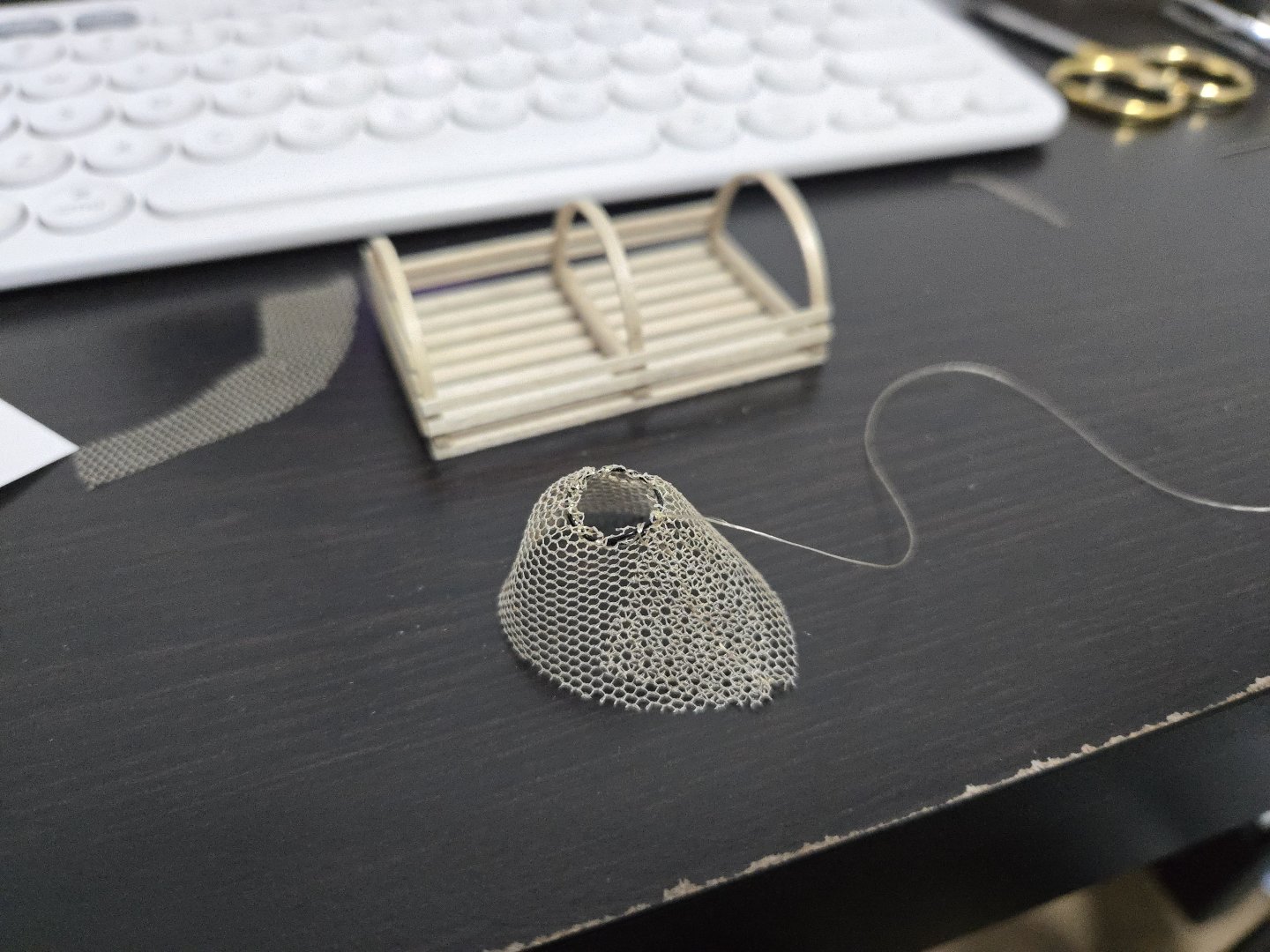
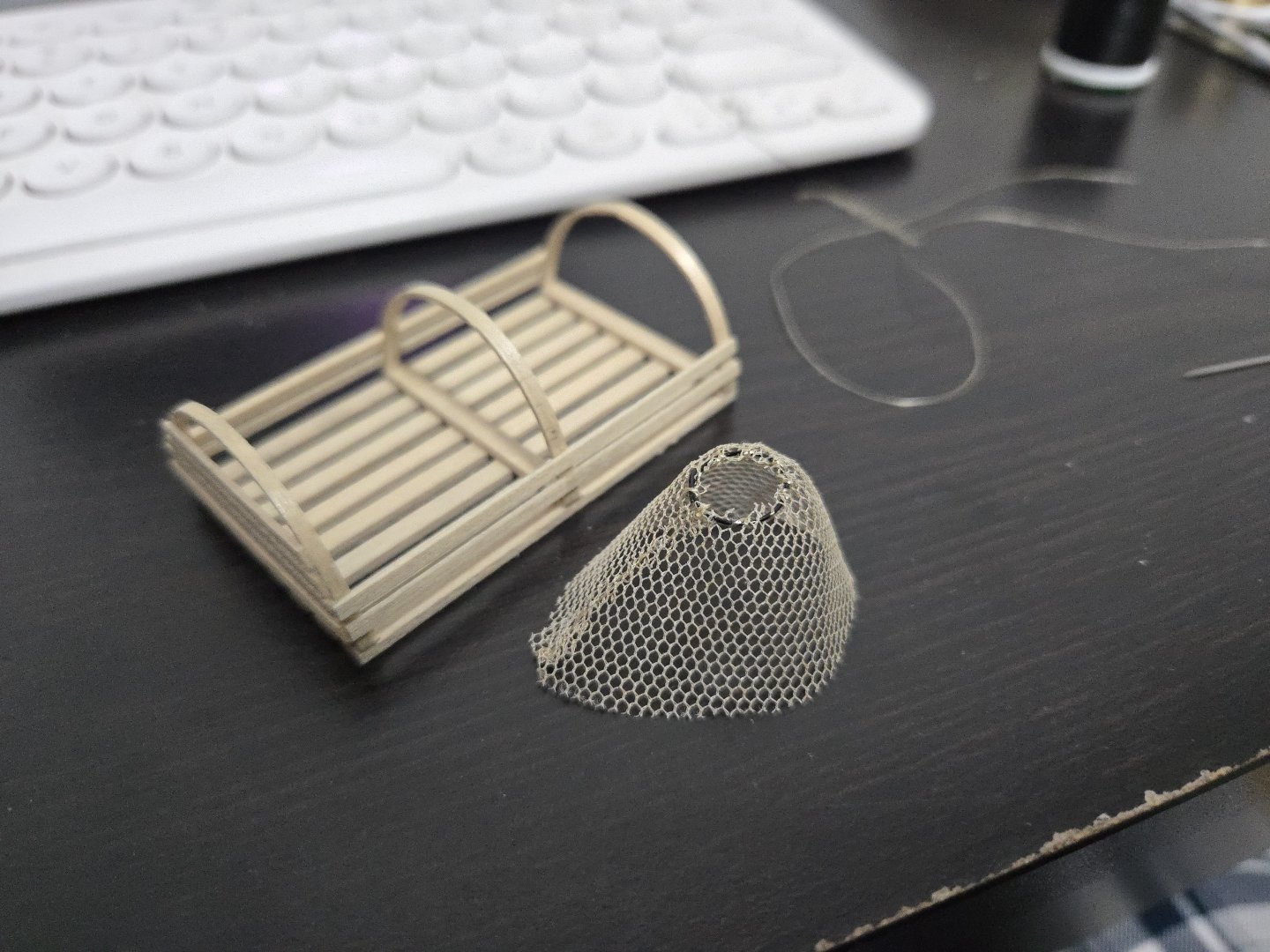
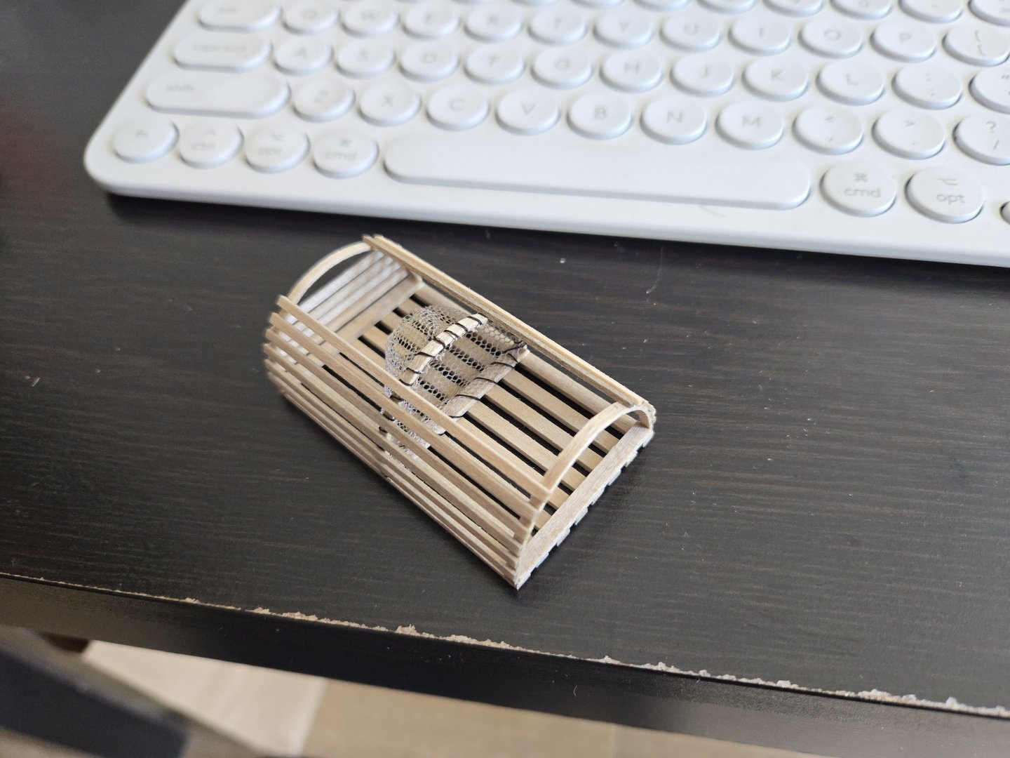
A bit more progress on the lobster trap. Based on my earlier experiences, I've been trying some new techniques. This is especially the case with the net funnels, which have always been a serious challenge because the tulle is tricky to work with--hard to glue because it's mostly gaps, and hard to sew because it's very light. On my earlier lobster traps, I made the ring by gluing a loop of thread, and I attached it to the net funnel just with superglue. This time, I wanted to give more structure to the net, so I experimented with making the ring out of wire and threading it through the tulle. This actually worked fairly well, and I think is the way to go for this process. As for completing the net funnel, I knew that sewing it could be a challenge because the tulle tends to just follow the thread. To give it more structure, this time I tied the fore end of the funnel, finding that it helped hold things in shape. After that, I sewed the funnel together. Trimming the loose overlapping ends finished off the funnel itself: Next, I had to attach the funnel to the trap frame. Although a brown or tan thread would be more accurate, I personally like the look with black thread, especially as this is already a bit of a stylized model. Unlike in the past, where I just sewed it directly in place and had a very hard time keeping the funnel aligned, this time I tied the funnel to the frame in three places (corner and top) so it would stay in place. I highly recommend doing this if you're making your own model lobster trap. I was then able to sew the net in place. As can be seen, I left most of the slats off for sewing the internal funnel, so that I would have more room to manuever. I just had to make sure the thread was properly spaced to fit between the slats. I've now begun adding the rest of the slats (leaving space for the opening on top), as the front-end funnel will be easier to sew in place with the slats on.

- 65 replies
-
- 6
-
-
-
- Maine Peapod
- Midwest Products
- (and 1 more)
-
Very cool! Looking forward to seeing how you get this one in the bottle.
- 185 replies
-
- 8
-
-
-
- Flying Dutchman
- Black pearl
- (and 2 more)
-
Thanks! I'm finding that it's ultimately more about the build experience than the finished product.
-
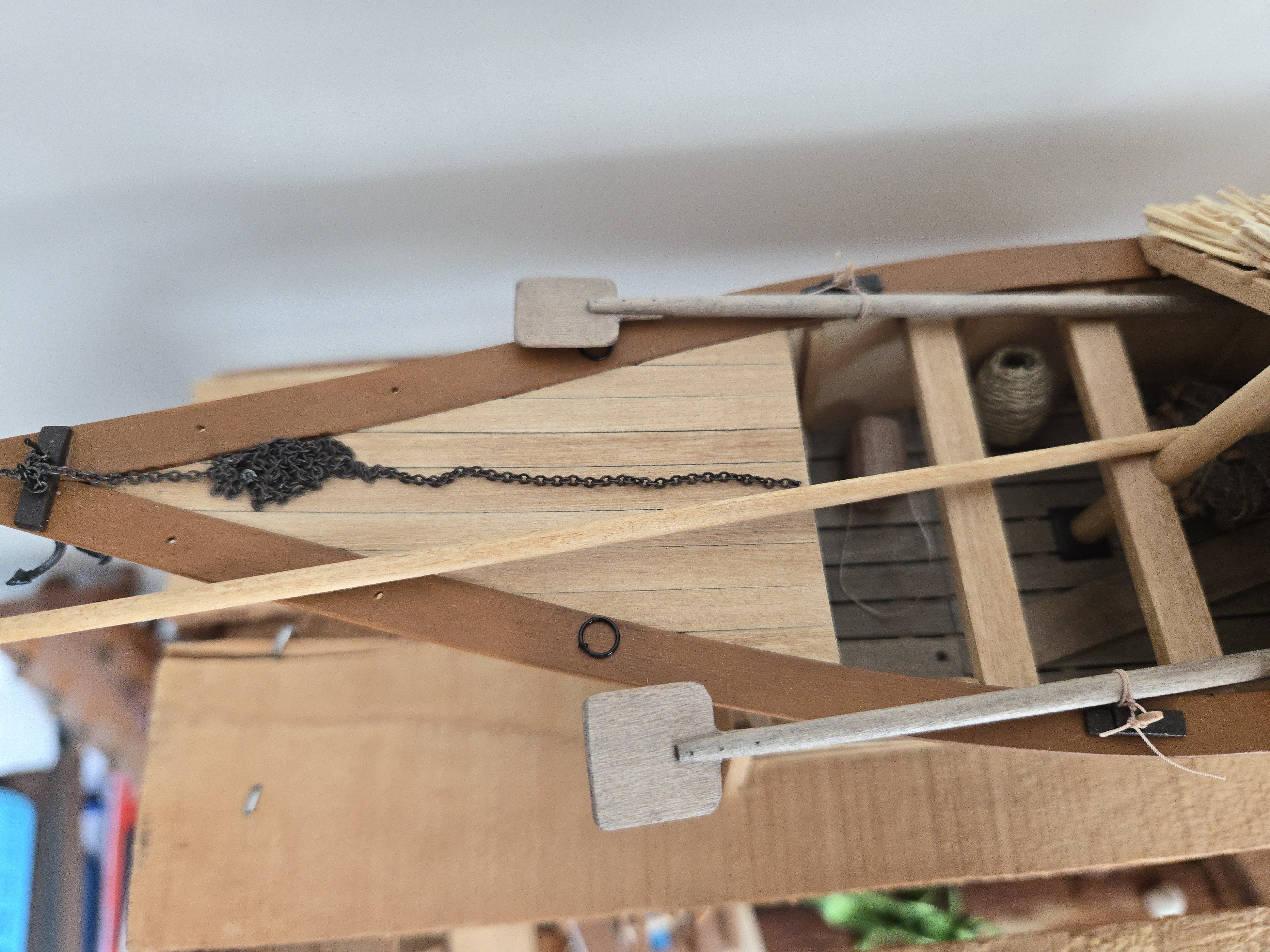
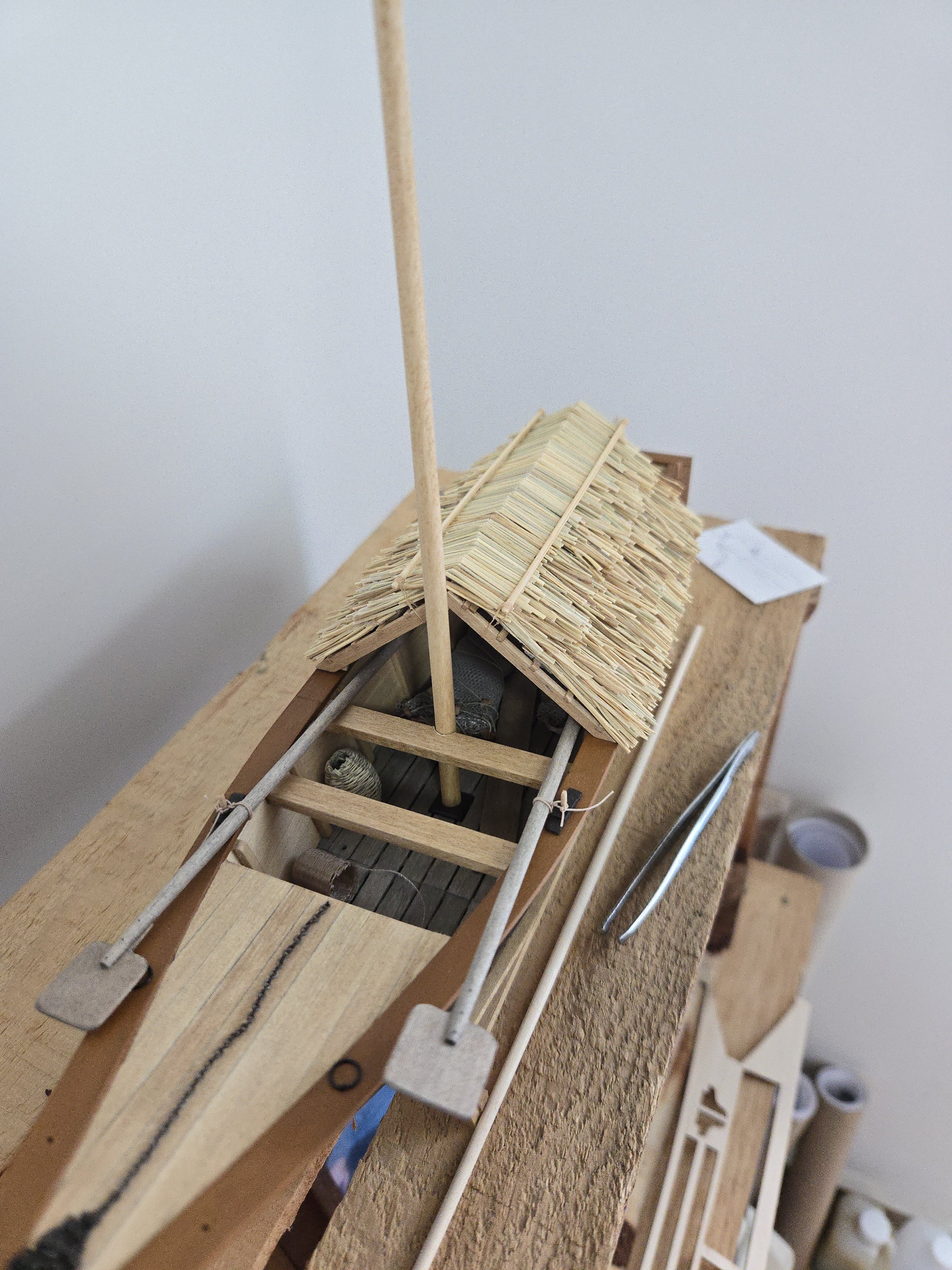
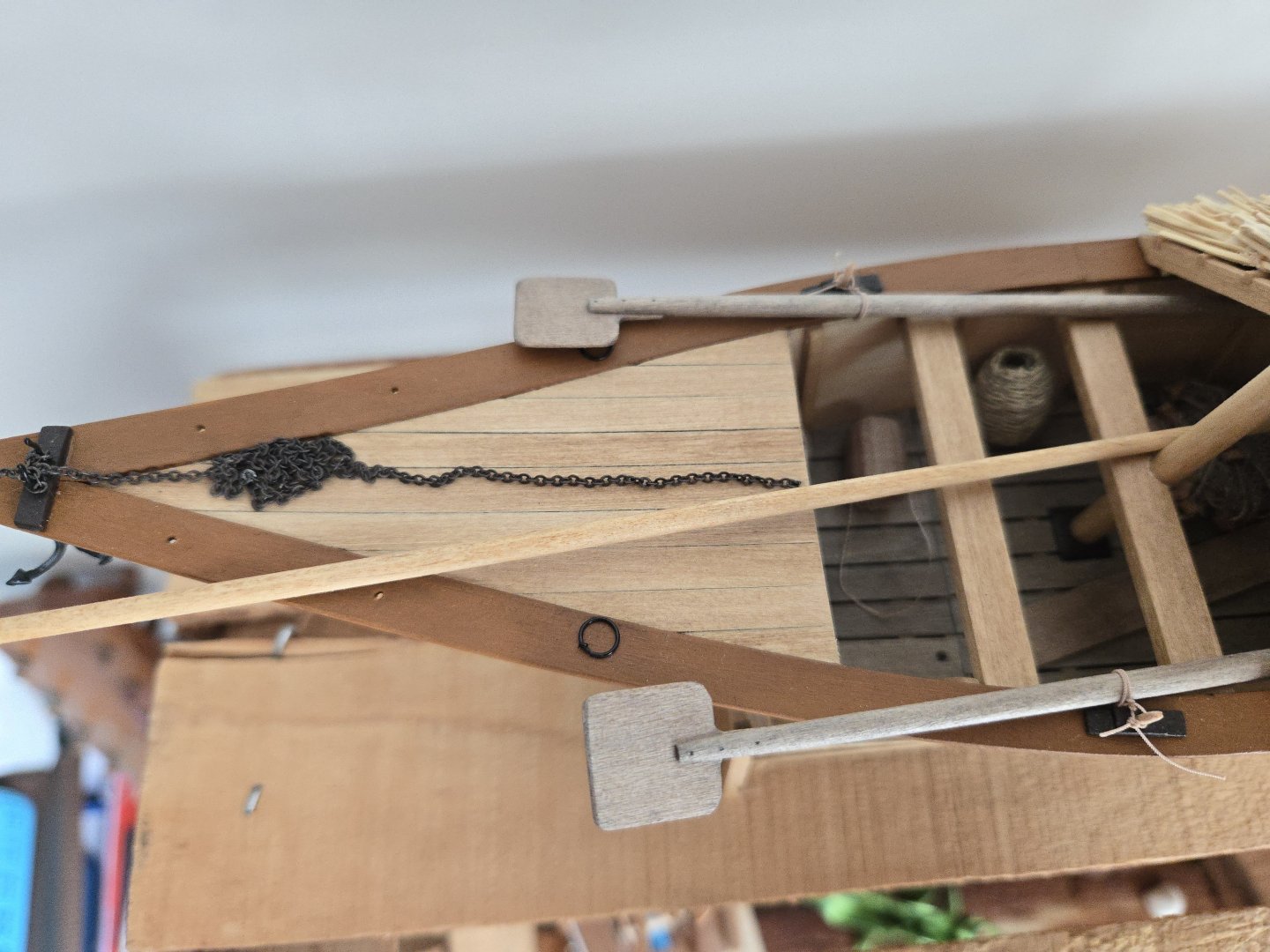
Definitely! I continue to be a bit blocked by my inability to find a stain that looks remotely similar to what I used earlier. I found one that looked promising, but, perhaps due to the different grain pattern on the yard vs. on my test scrap, it turned out much redder than expected, as seen below. I'll see if I can sand it out, or may have to make a new yard. At this point, frustrating though it may be, I may just have to wait until I visit the US in a month and pick up the proper stain there. In other news, I also wrapped up the fishing nets to store them, using a dab of matte varnish to secure them. In hindsight it was definitely overkill to do as much work on them as I did, given that they're quite hard to see under the rancho. Nothing is glued down yet, as I'm just testing out locations, so I may move them a bit so they're more visible. It's a fine balance between showing them off and blocking the view of the internal structure of the hull.


-
Very curious to see how you kit-bashed this one!
-
I had the same issue (as have a lot of people) and found that lining up the fore two slots by trimming the aft end still left the aftmost slot slightly off, which I corrected when I deepened the slots.
- 84 replies
-
- 5
-
-
- half hull planking project
- NRG
- (and 2 more)
-
Congratulations on finishing, nice job!
- 28 replies
-
- 3
-
-
- Lowell Grand Banks Dory
- Shipwright Series
- (and 3 more)
-
Looking forward to following along with this build!
- 84 replies
-
- 4
-
-
- half hull planking project
- NRG
- (and 2 more)