


Der Alte Rentner
-
Posts
282 -
Joined
-
Last visited
Content Type
Profiles
Forums
Gallery
Events
Posts posted by Der Alte Rentner
-
-
20 hours ago, Geoff Matson said:
Hello Peter, I love your build and look forward to your progress. I hate to age my progress, but I have been at this on and off for over 10 years. If I can answer any questions for you just ask. I used Bob Hunt's Practicum and could not have got this far without it.I also added a lot of my own way to solving some of the construction problems.
Thanks Geoff,
It will be some time before I get to the rigging, but having your build log to draw inspiration and techniques from will be a blessing when I finally get to that stage of the build - hopefully in less than 10 years.. 😉
-
-
On 1/1/2024 at 1:40 PM, mtbediz said:
If you do the edge bending the planks in the bow section of the ship, you will see that the planks fit exactly onto the bulkheads and you will get a smoother surface. As you can see in the photo, I do the edge bending with the help of an iron.
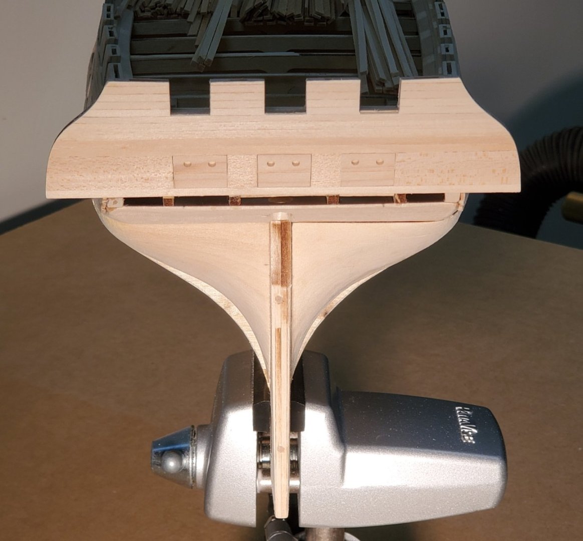
I have been edge bending, which has really only been necessary for three of the strips on each side. That isn't the problem, as you can see in these two photos.

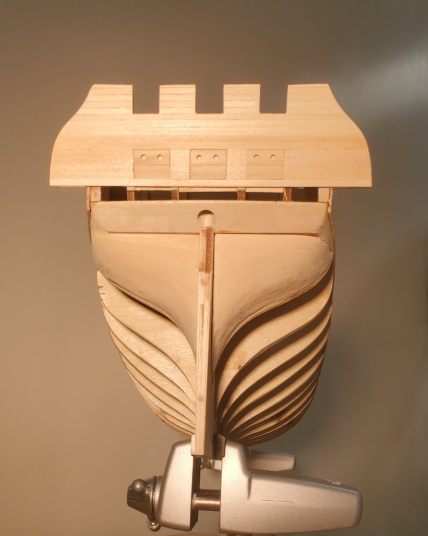
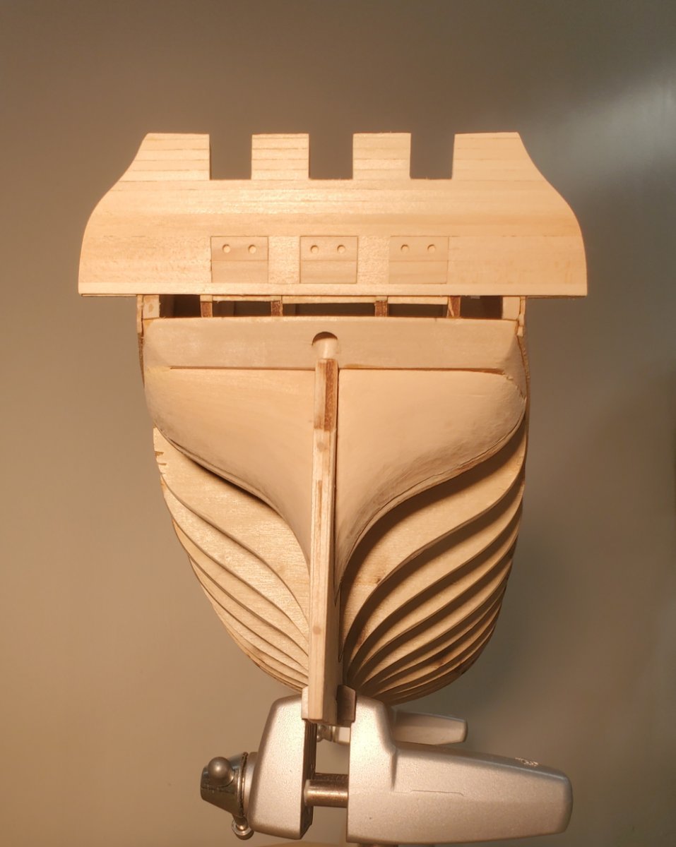
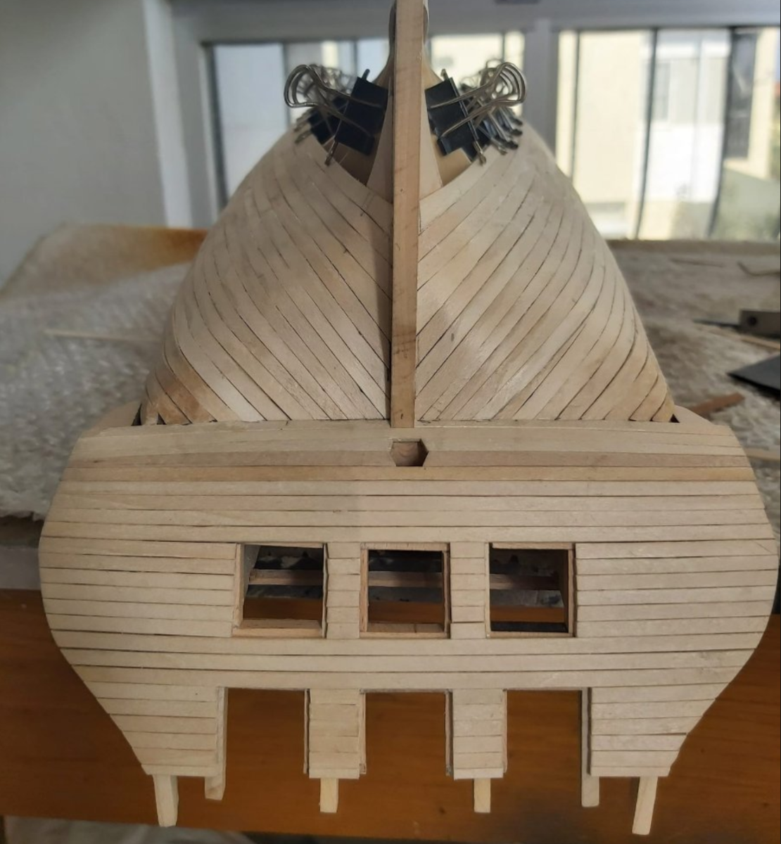
I'll try capture the waviness issues in a photograph when I return to the shipyard. But a second issue has surfaced that I should have addressed a few strakes ago. It may be more problematic than the waviness. Look carefully at the photos below - at the wale at bulkhead D. It doesn't seem so blatant when viewed deck side up (first photo - taken after 7th and final wale strake installed), and may yet more-or-less disappear when the planking is done.

But it's distressing when viewed keel side up (older photo with only 6 strakes on).

Thank you for the tip of the bending technique with the iron. I saw an earlier post of yours where you showed your method for bending the planks at the counter. I've been doing that last twist by hand after bending the plank with a plank bending tool. But I like your bending jig option and will adapt that going forward.
- mtbediz and Geoff Matson
-
 2
2
-
19 hours ago, woodartist said:
As a newbie, I made a Newbie mistake, I was given a Model Shipways kit for the USS Constitution. Despite a lot of advice to the contrary I started in. I got quite a ways before I realized I had made enough mistakes that impacted the ability to finish it successfully. I trashed it, and started a scratch build, I have worked on it for two months and so far all is well, in large part due to the build logs of Der Alte Rentner, MTBediz, and JSGerner, however, I need a break from the Conny. So I looked for another boat to build that was more suitable to a Novice.
Say it isn't so! I was counting on you, as the only other Newbie, to keep me company on my build of the Constitution. Not having seen a post from you in a while, I did a look-see, and learned you've abandoned ship. That is sad news to me, but I'll follow this build to see how you fare.
Best of luck on the new build.
and Happy New Year.
Peter (aka Der Alte Rentner)
-
On 10/17/2023 at 9:30 AM, Geoff Matson said:
Here is one of my favorite pictures looking through the aft gun ports down along the cannons on both sides.
Hi Geoff,
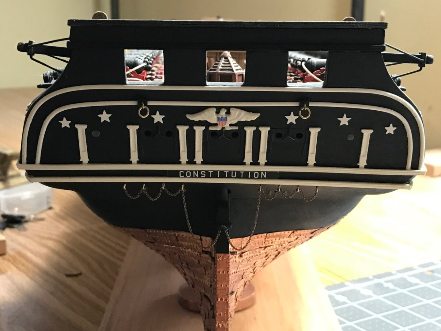
I'm responding to your post to JBGibson, where you showed that stunning closeup of the transom.
I've looked at your build log in the past and was chagrinned to see that you began posting with the rigging. I would love to see how you progressed from the beginning to the point you started posting.
Am I just not aware of where to look? Or is there no documentation of your earlier work on the Constitution?
Best,
Peter
- SUBaron and Geoff Matson
-
2
-
-
21 hours ago, JSGerson said:
This is in essence how I planked my hull. A lot of “How to” articles and build logs use the tick mark method and proportional wheels or dividers. I just could not draw a pencil line on the hull that precise and get a strake to properly taper and fit. Like you I mathematically determined the width of the strake at every bulkhead point and sanded away, checking with the micrometer. I just didn’t do it with a nice spreadsheet. I worked each strake, one at a time, marked the determined widths on a piece of scrap paper. Once done, I discarded the paper. You did a fine job.
Jon
Thanks Jon, For what it's worth, I didn't use the spreadsheet at the shipyard. I prepared it rather than run back there while updating my personal build log to retrieve and photograph my pieces of scrap paper.
I am noticing as I work, that the hull itself has a wavy surface now. Evidently, fairing the bulkheads wasn't as precisely done as I would have liked. It's more noticeable with the hull upside down, but even right side up, I'm aware of it. I don't know how well I'll be able to flatten the surfaces later, if at all. I suppose this could lead to me painting the ship anyway - after applying corrective wood filler. Time will tell..
Happy New Year
-
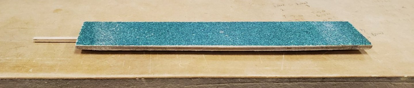
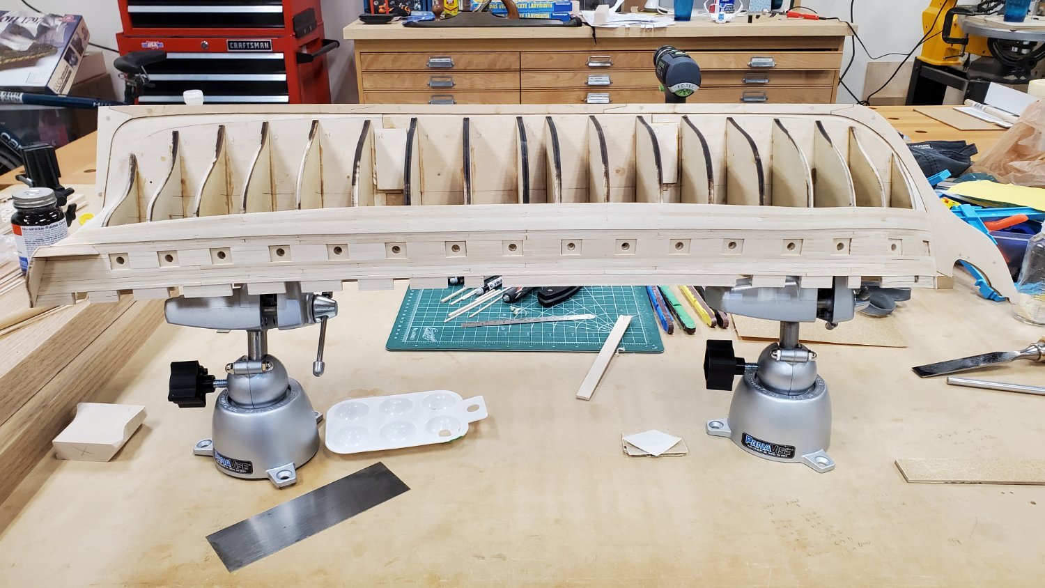
Work continues on the port side wale.
This may be way too much detail to post at the website, but I’m adding it to my personal build log, so I may as well show the steps I’m using to shape the wale segments.
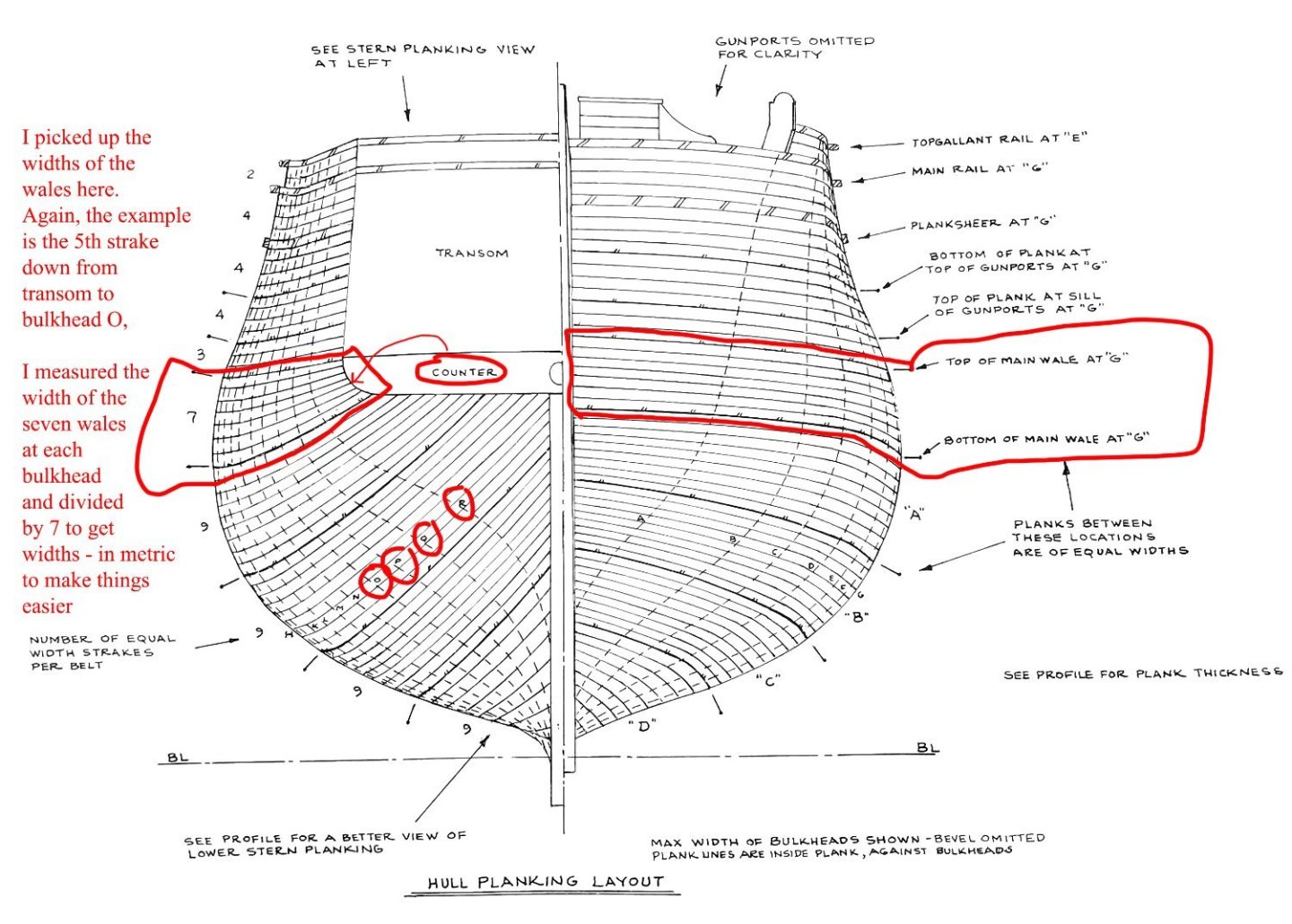
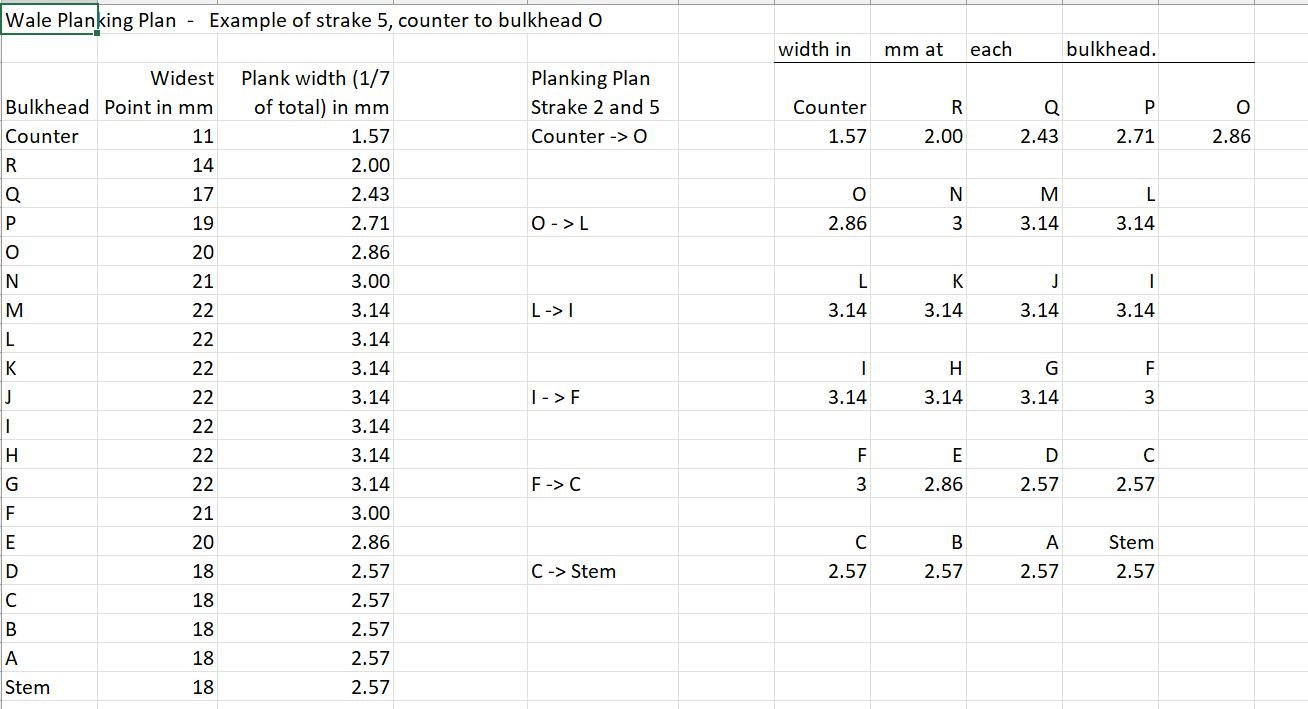
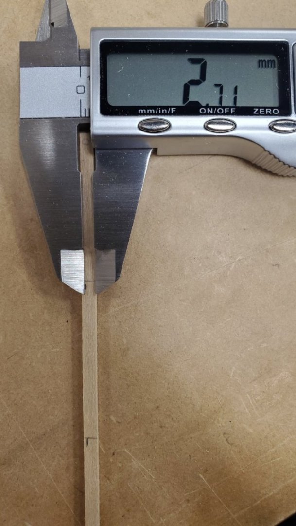
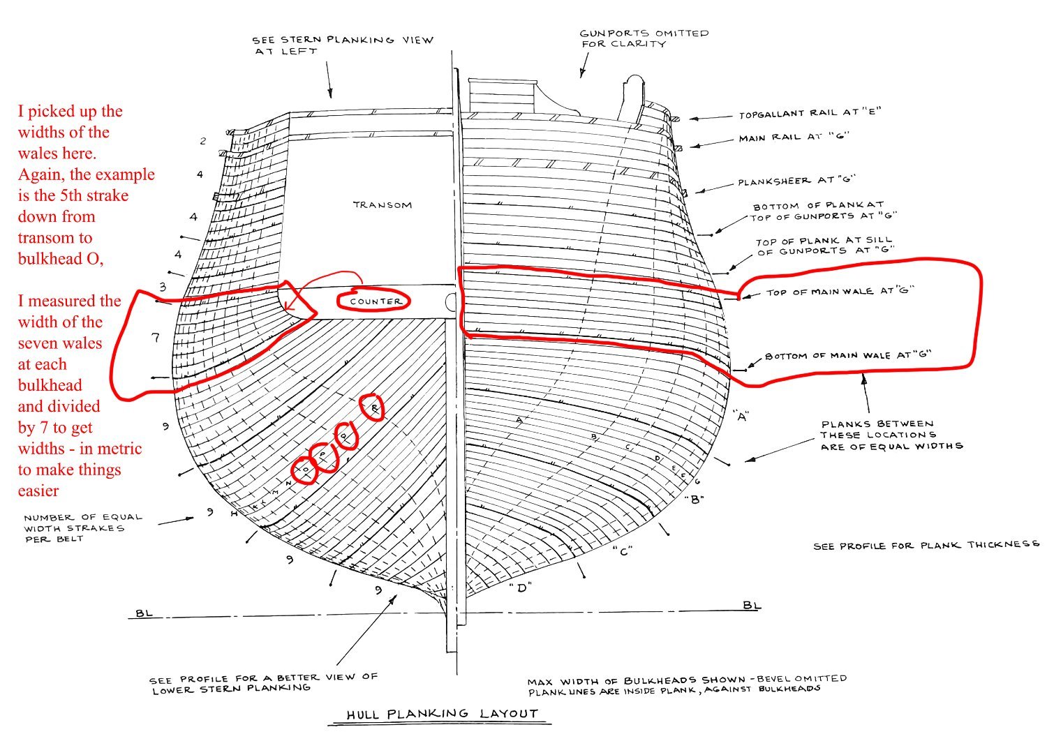
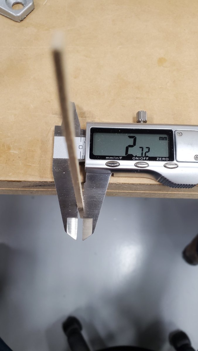
I started with the plans (page 3), which show the width of each zone of planking. Focusing on the wale for this step, I used a flexible measuring tape to measure the full width of the wale at each bulkhead. I then divided by 7 to get the widths for individual wale segments.
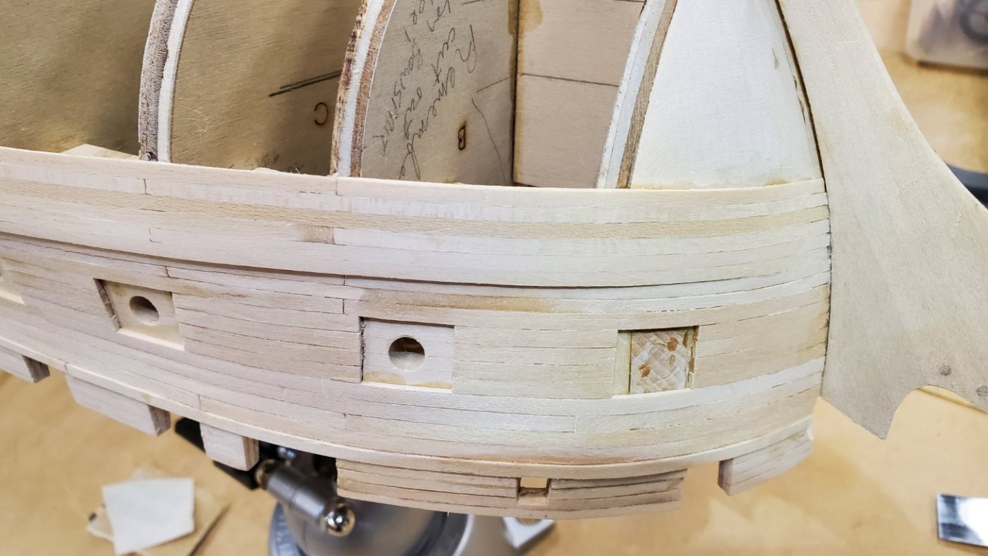
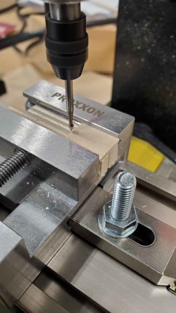
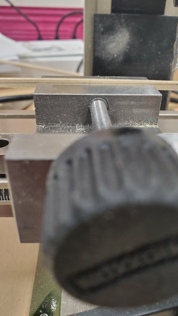
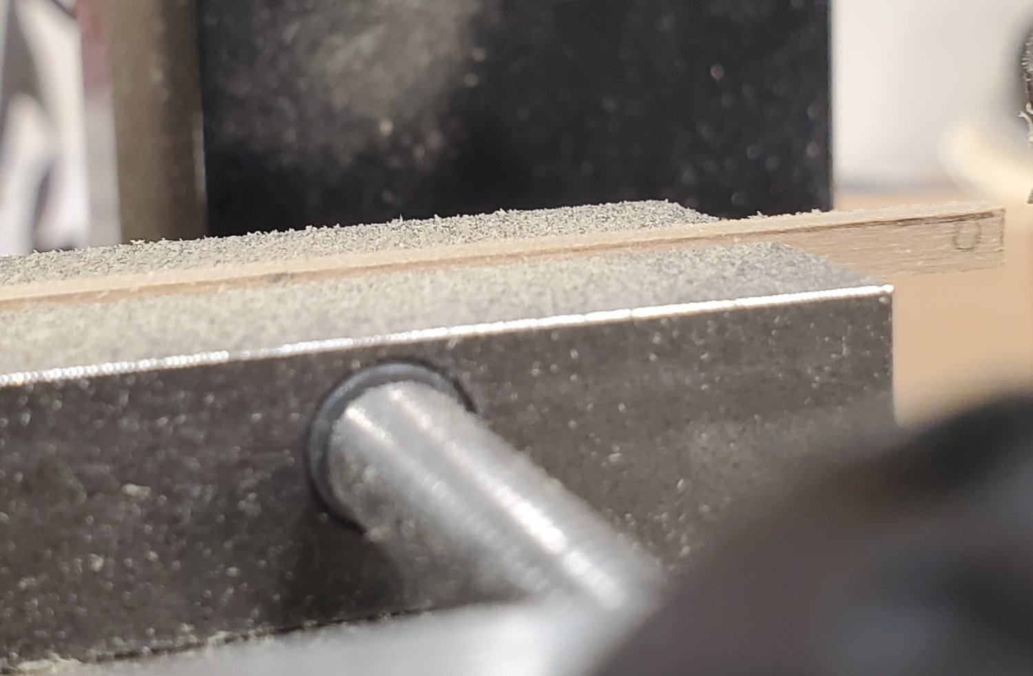
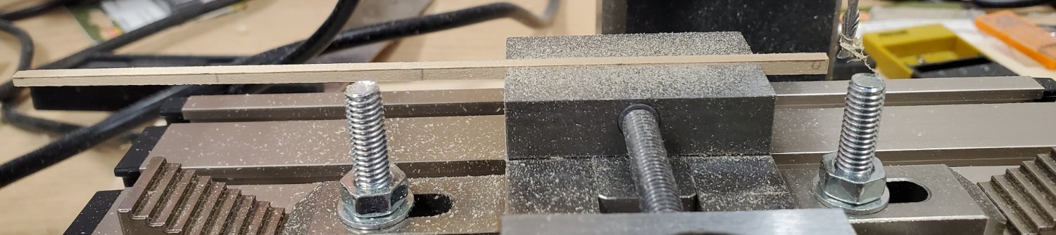
Putting together a planking order, so as not to have butt joints one above the other, I then transferred the dimensions to a grid. The dimensions were marked at the points on a wale segment where the segment contacted the bulkheads. A line was drawn connecting these marks and the piece was clamped into the vice of my Proxxon micro milling machine with the line parallel to the vice jaw. I milled to the line, which got me close. Then fine tuned the material removal with a sanding stick. Finally, I beveled the bottom edge of each segment to facilitate tighter bonding surfaces.
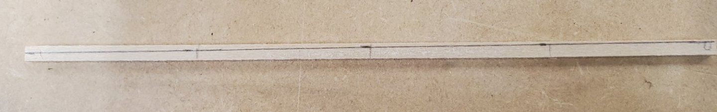


The segments are usually much wider than the vice jaw. In this case, after milling say from one end to the middle, I move the piece so that the previously cut part is outside of the jaw. This sounds dicey, but actually works pretty well.
The key is to keep that pencil line at the same distance above the vise jaw. With good magnifying glasses and light, no problem..

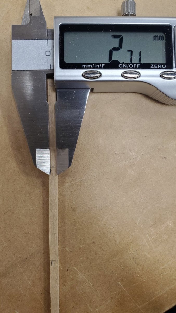
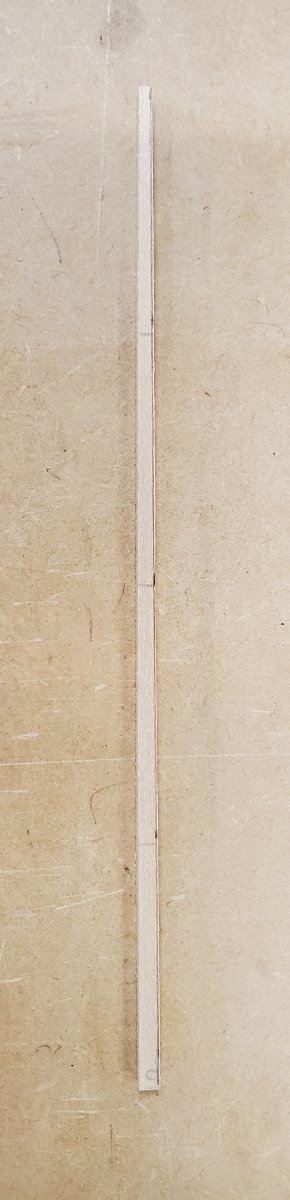
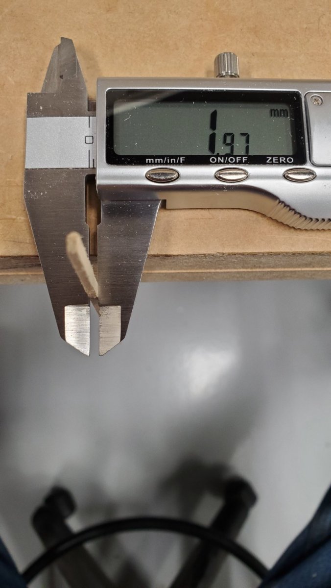
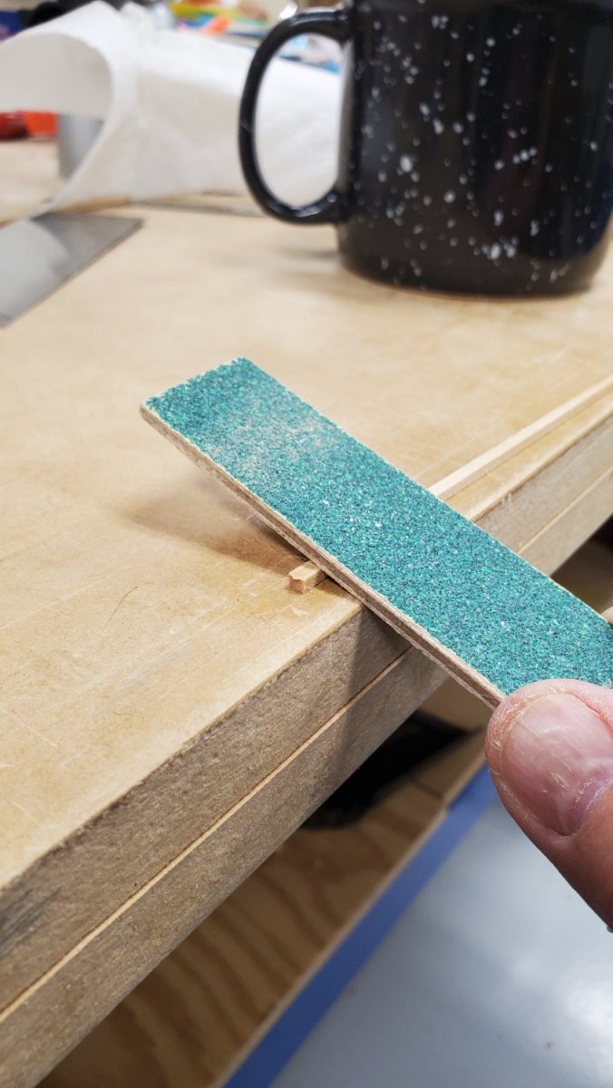
The milling gets you very close, but to really nail it, you need to use a sanding stick.
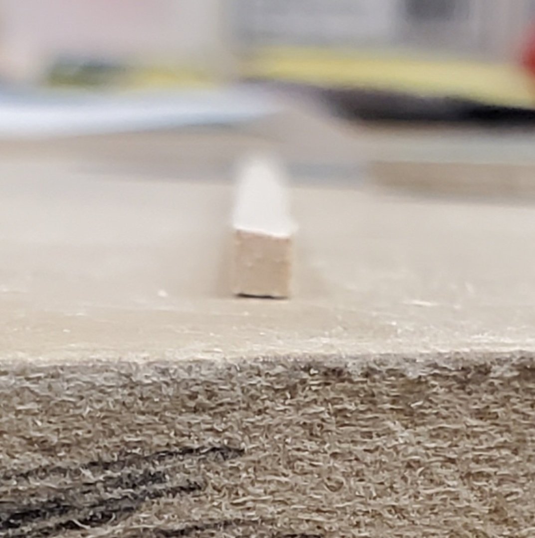
Proof positive that you can get very precise tapering.
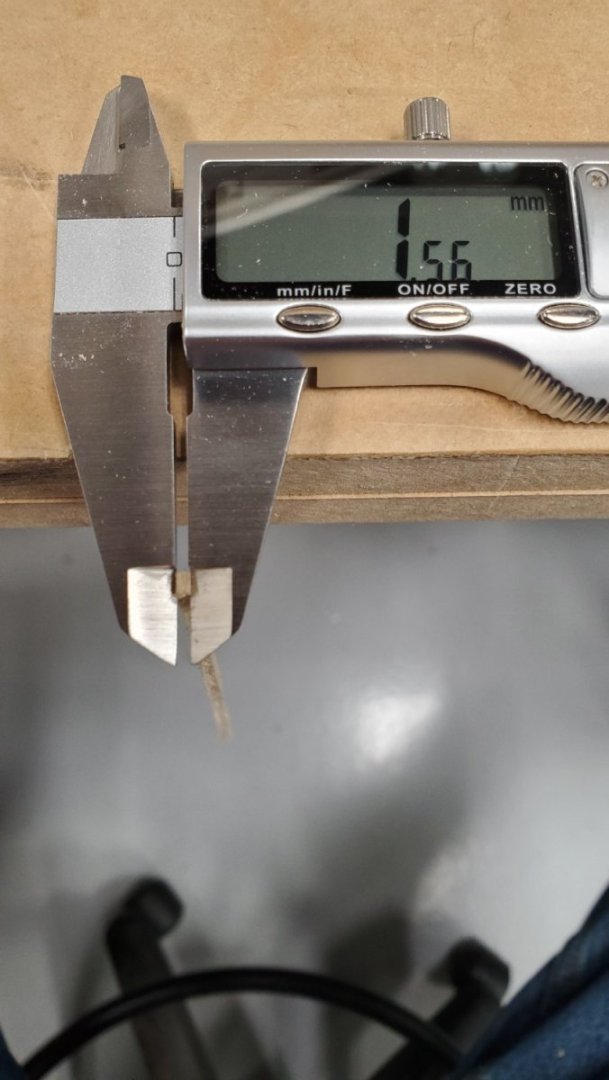

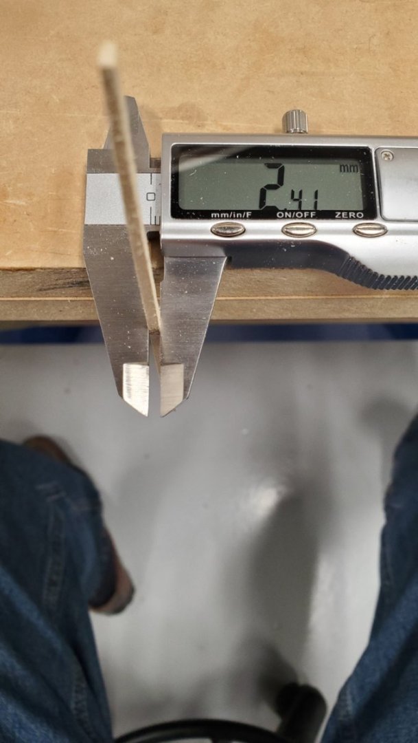

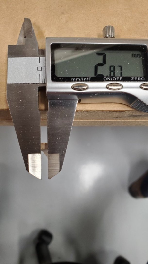
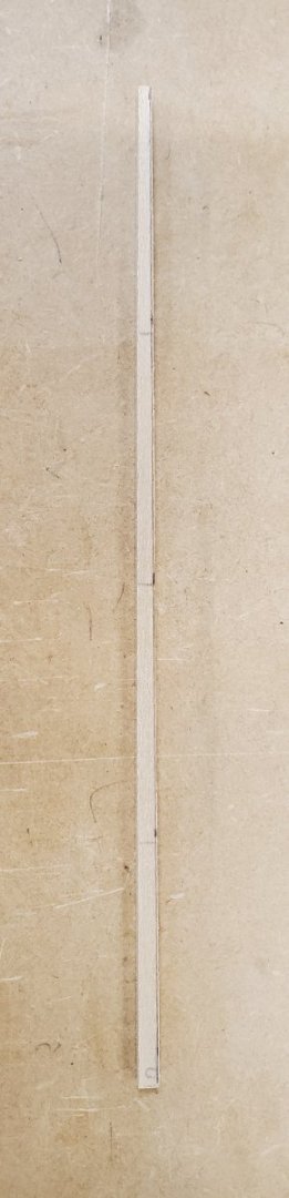
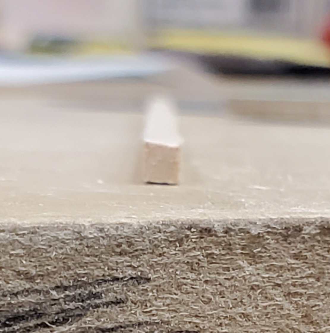
A dry test fit should confirm if the piece was properly tapered.
But there’s more shaping to do. To get a better fit when gluing the piece in, I bevel from the outer face to the bulkhead face on (in this upside down configuration) the top edge of the plank.

I spread Titebond glue on the upper face of the previously installed strake, and use gel super glue at the bulkheads. This technique minimizes the use of clamps, as the super glue sets quickly. The Titebond glue sets up more slowly, but does a nicer job of filling the gaps.
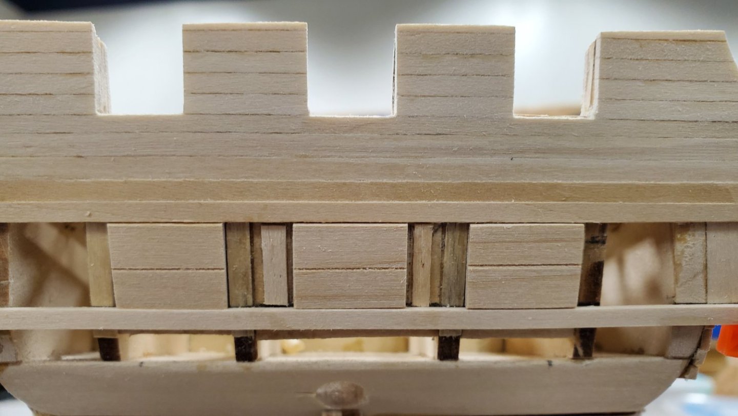
Then it’s time to get busy with the chisel and get the faces nice and smooth. ( I started in the photo below). That’s followed up by passes with successively finer grits of sandpaper to really smooth things over.
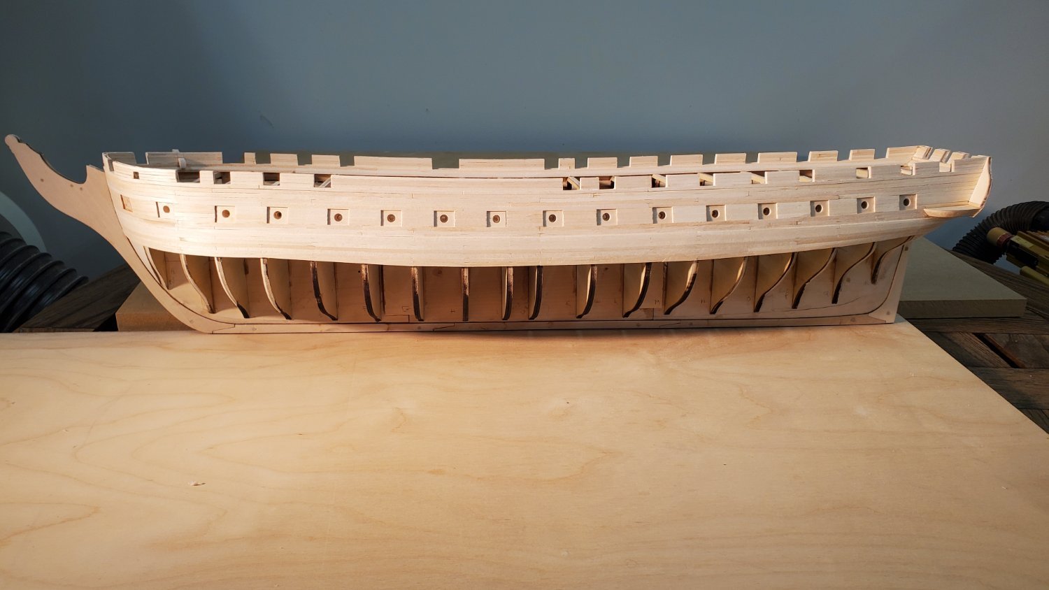
Five strakes down. Two more to go on the port board side, then seven on the starboard. At four hours per strake, I have about a week’s work ahead of me to finish the wales. I won’t chime in again until I’m ready to move on to the lower gallery pieces.
-
3 hours ago, JSGerson said:
I checked the US Navy plans and the wale does exist but is not as pronounced on the surface of the hull as the MS plans make it out to be. At best, the wale bumps out at its thickest point about 3.5" from the hull or about 3/64 at scale." and even that change is not as abrupt as the MS plans show. To see that fine detail in very old images is unlikely.
Also, the Navy plan you supplied shows the wale is tapered. Perhaps that's why it doesn't show in the 1914 photograph. I looked long and hard to see a bump in the MS plans, and didn't see any. I'll proceed with stock that's slightly thicker than the 3 rows of planking directly above the wale to allow me some flexibility when fairing the hull.
Jon, your interest an knowledge of these little details is unparalleled. Kudos to you!
- mtbediz and Geoff Matson
-
2
-
-
On 12/22/2023 at 8:49 AM, JSGerson said:
The simple reason is that it is thicker on the actual ship as well as it is on the plans. I'm no expert on ship design, but I assume the added thickness is for added strength when docking and bumping into things. These ships are often rolled on their sides for maintenance too. See foreshortened image below.
Your photo does suggest that there is some added thickness in the recent edition of the Constitution. I did not see that in the Aug 18, 1914 reference photo I supplied above. And compared to Bob Hunt's example, the wale in your latest photo is subtle indeed.
Since we're confabbing on Mtbediz' dime, I'll add that Mustafa seems not to have added thickness there either.
Because I've already shaved some of the existing planking between the gunports and where the wales are supposed to begin, the difference in thickness I'm looking at is even more severe than in the Hunt Practicum photo. I'm pretty good with a chisel, but if I add the wale, I think I'll be better off using stock that's a little thicker than the existing planking - not the 3/32 x 1/8" material Bob used in Chapter 6. That should make shaping the planks at the stern somewhat easier too.
Thanks again Jon
-
Unrelated to the previous conversation:
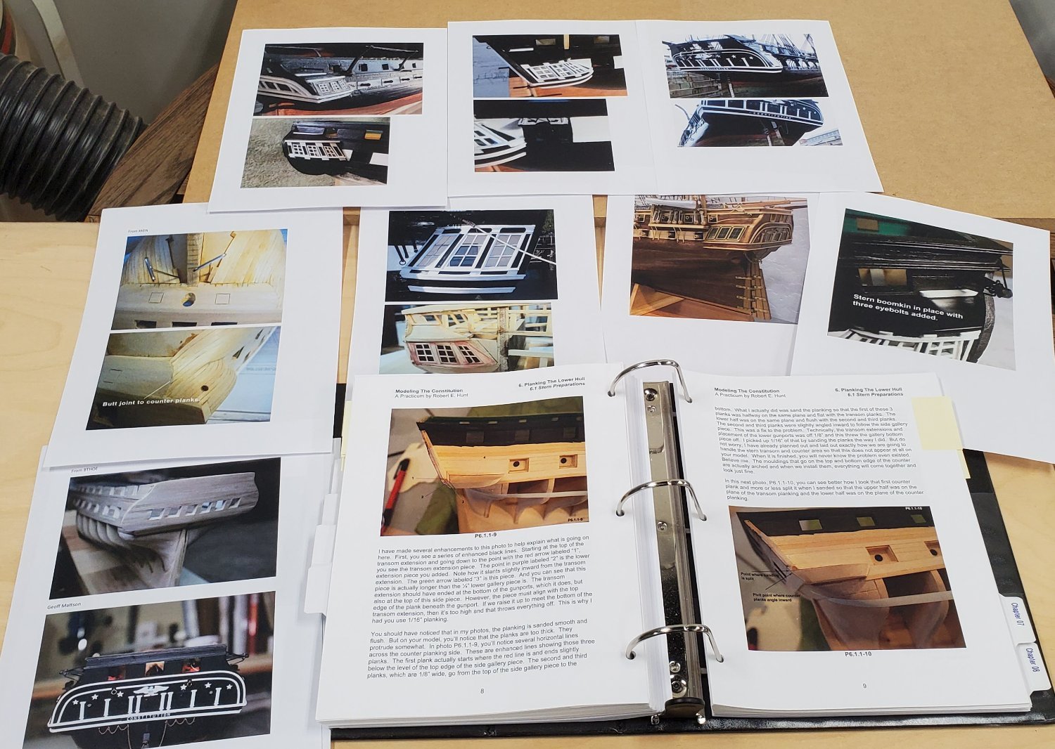
Just a word of thanks Rich. I was starting the planking of the wale yesterday and stopped to do some research. I posted a question in my own build log on the subject, but then did a search on "Constitution wale" and among the results was your build. I spent the morning poring over it, making notes, "borrowing" photos, and comparing to the Practicum. Your photos provided much more detail than those provided in the Hunt Practicum and have solidified in my mind the process going forward. I copied some portions of your planking discussion and printed it to have on hand at my shop.
Thanks for posting such exhaustive detail. (and for chiming in with opinions and answers when I've inquired)
Saint Nicholas Day has come and gone, So
Merry Christmas and Happy New Year to you!
Best
Peter
- ERS Rich and usedtosail
-
2
-
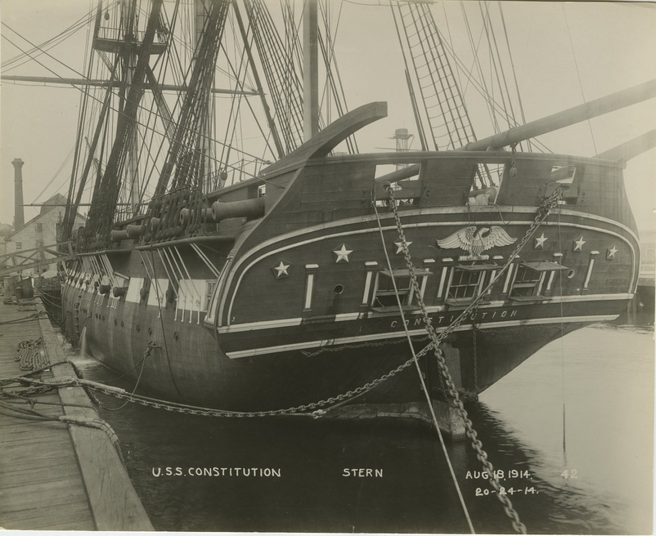
What fortuitous timing on your providing photo documentation, Jon. I'm just about to start the wales (Chapter 6 of the Practicum) and was wondering why Bob Hunt was using thicker stock for those 7 strakes. The plans don't really show any difference in the width at the bow for the wales. Many models I've seen at this site also seem not to deal with this detail. The photo from 1914 above seems to confirm that there's no difference in the planking thickness between gunports and waterline.
Here's a photo from the practicum:
That begs the question, why bother with thicker stock?
Thoughts gentlemen?
-
2 hours ago, JSGerson said:
What wood did you use and how did you soften it up to bend it?
I have the same question.
Also, how many hours a week do you spend in your shipyard? I just spent 4 hours adding 7 rows of planking from the transom to where the rudder post will be. Very impressive productivity Mustafa!
-
-
1 hour ago, JSGerson said:
I've spent many hours researching through my photo library, Google, a multitude of build logs (both finished & in progress) and yet for some reason, my model doesn't look any different than it did before I started hours ago. Is that considered time spent building the model?
Jon
Ha! Well said!
-
23 hours ago, GGibson said:
Carry on, sir! Enjoying watching your Conny build! 👍🏆
Thank you kindly, sir! Many hours at the shop today with little to nothing to show for it. I'll resume after the pulled-out hair grows back. I suspect there will be wood putty application in the immediate future..
-
2023 Dec 14. Planked the part of the stern transom.
After much deliberation, I have decided to move to Chapter 6 in the Practicum and continue planking to the keel. Chapter 4 diverts to the spar deck details, after planking a portion of the stern transom (Chapter 4.1). I’d rather work with the hull upside down when I start planking and from what I’ve seen in the Practicum, this is slightly problematic if I carry on with instruction in Chapters 4 and 5.
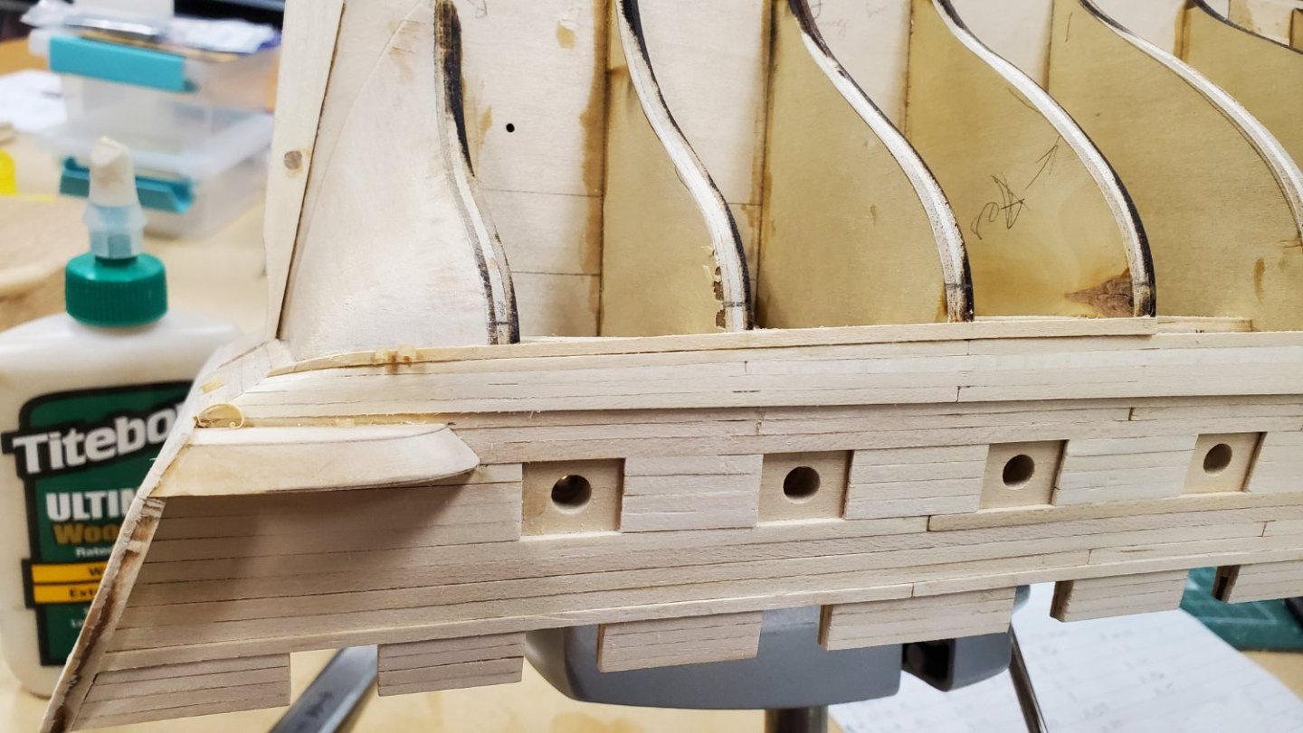
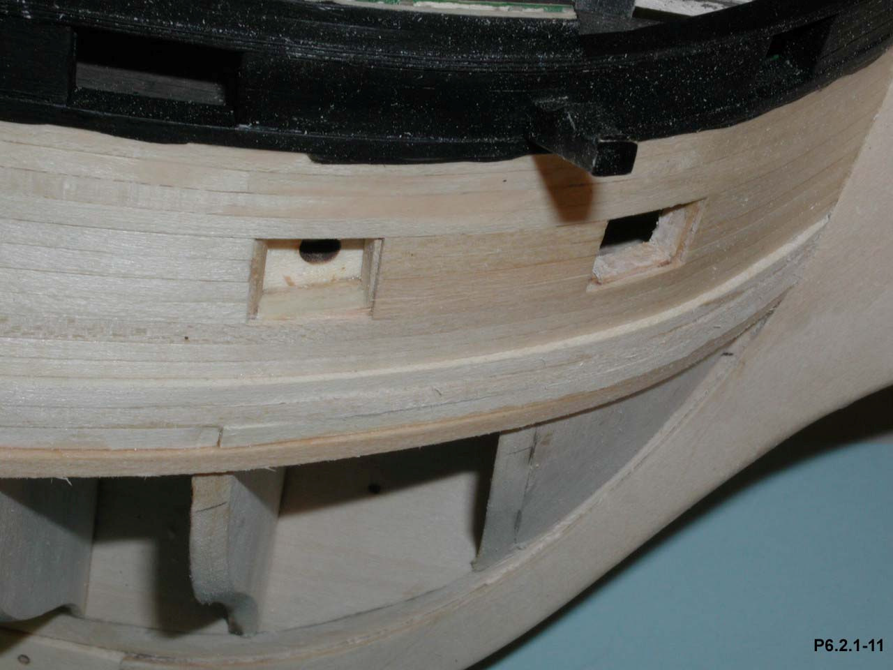
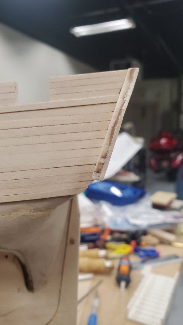
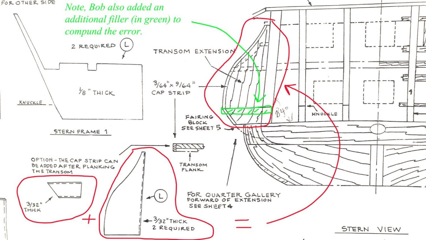
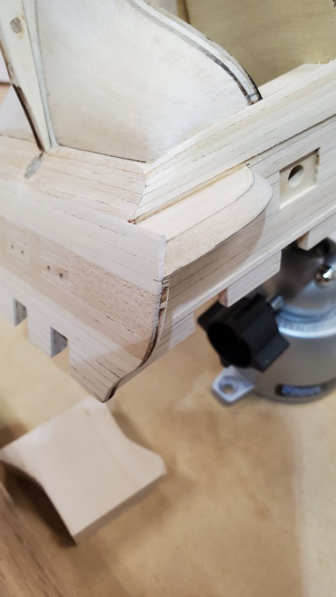
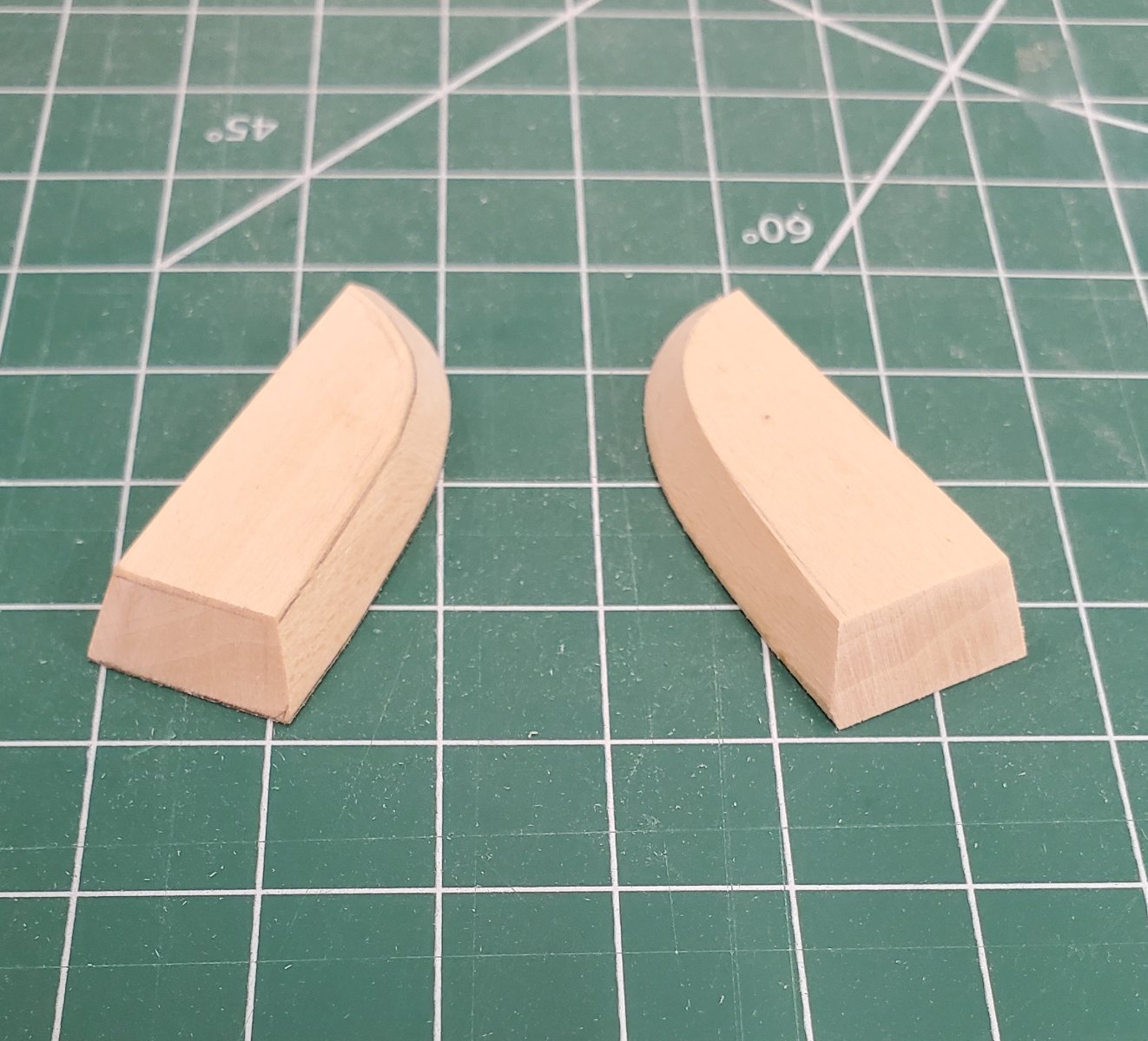
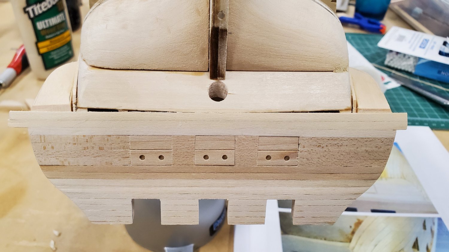
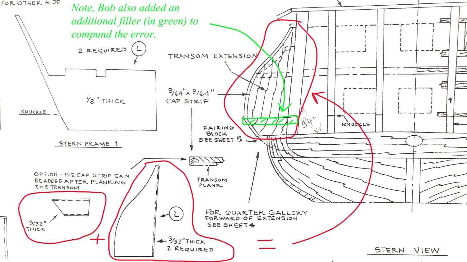
Now that I’ve had the benefit of a couple of days intense study of the process laid out in Chapter 4.1 and continuing with Chapter 6, I’m more than a little miffed at Bob Hunt. In Chapter 4.1 Bob observes that “..with the transom extensions ending where they do, this alignment is off and I had to compensate for it by adding a small piece of 3/32” wood to the bottom of the transom extensions to make them slightly longer”. Then in Chapter 6.1.1 “Planking the Counter”, Bob addresses the counter extension, which attaches to the transom extension. For Pete’s sake, why wasn’t this counter extension added to the transom extension when that was installed? Furthermore, one could ask, why wasn’t the laser-cut piece for the transom extension made to include this extra material. To futz with this crap now is a royal pain and could have easily been avoided. Sigh…This photo could come after the diagram, but it illustrates the filler material I just added per Hunt Practicum instructions in chapter 4.1 Adding that counter extension will be an adventure now...
Okay, enough carping, I’ll deal with it later…
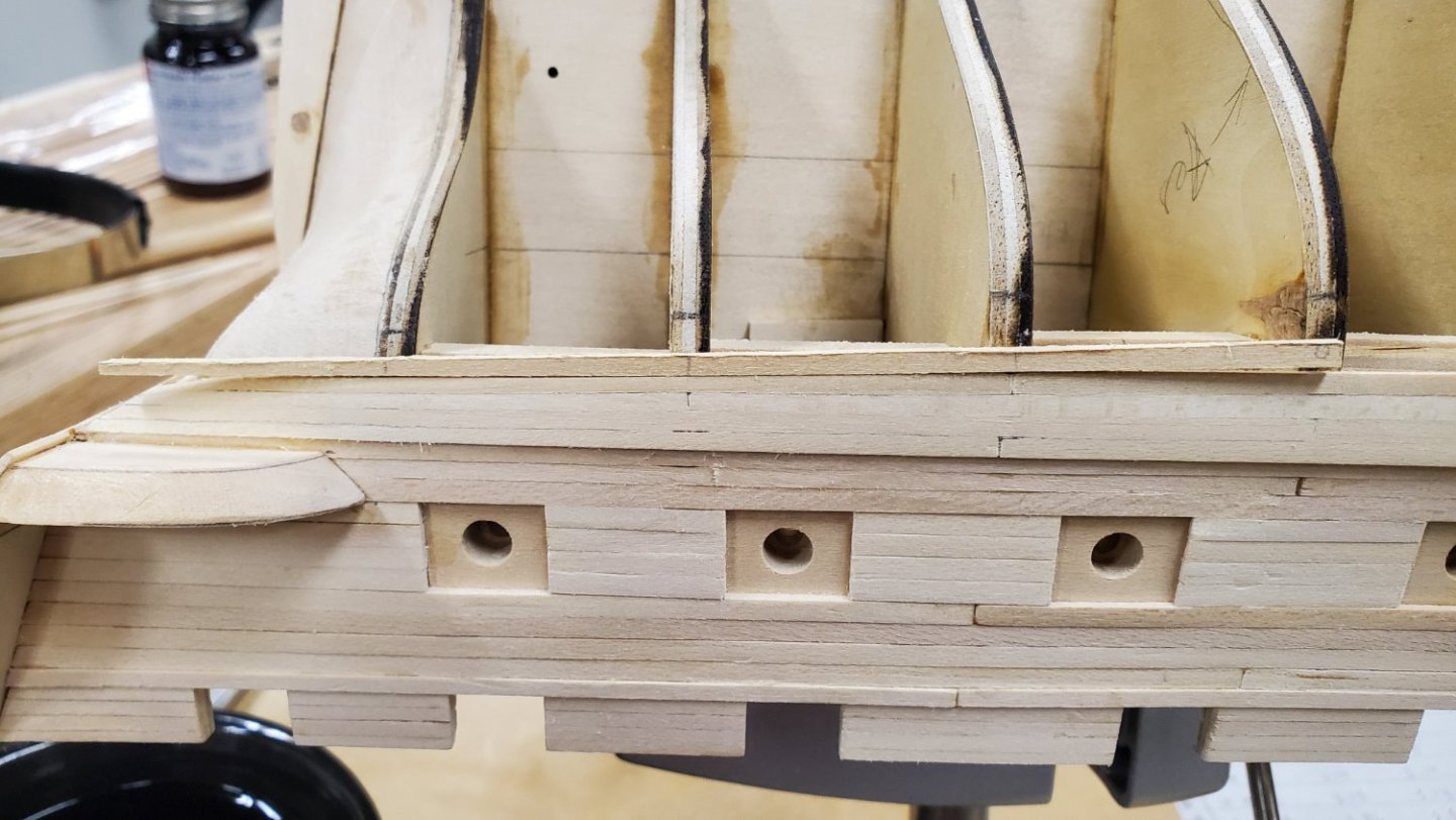
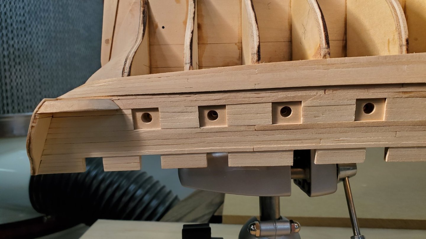
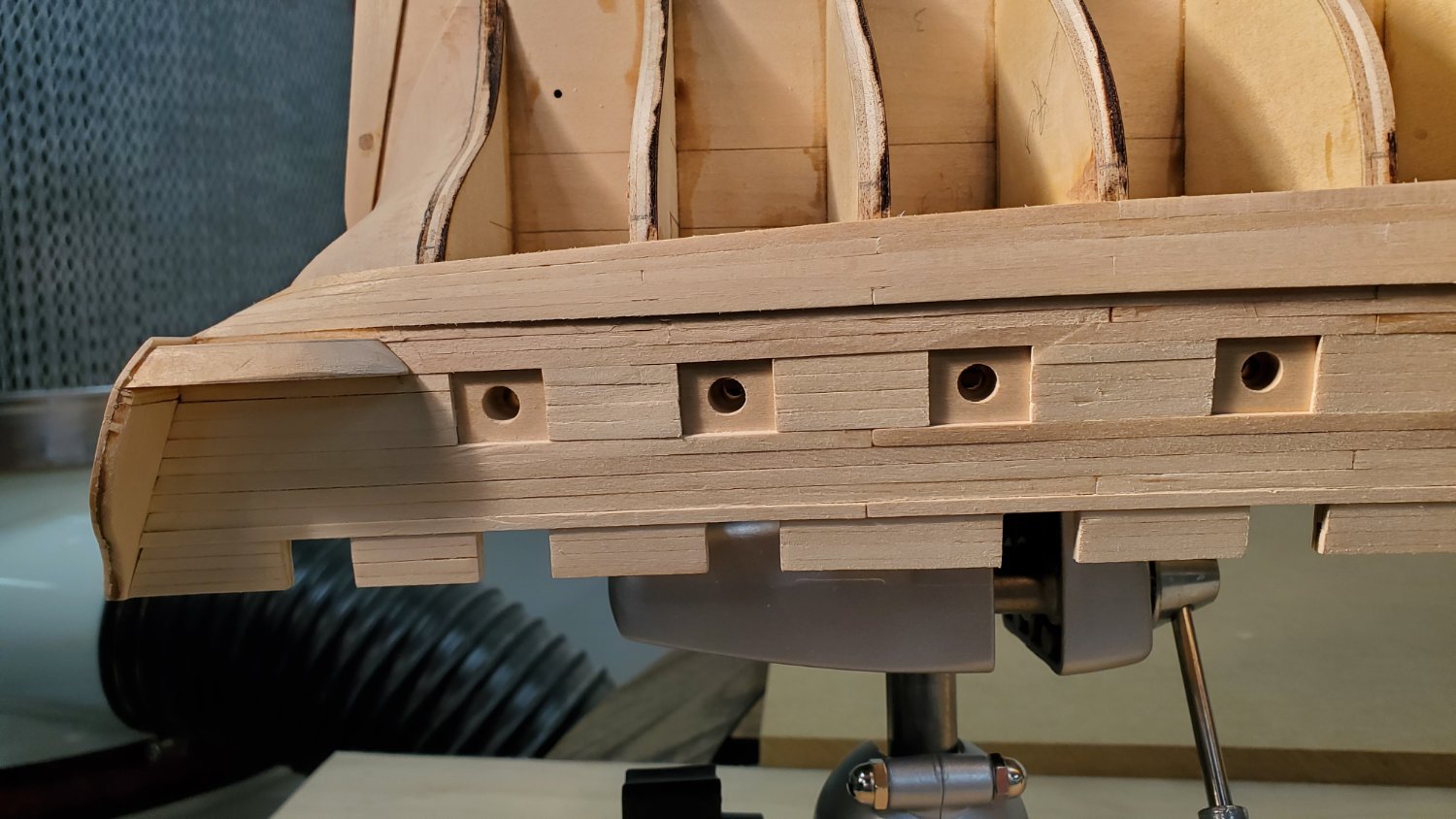
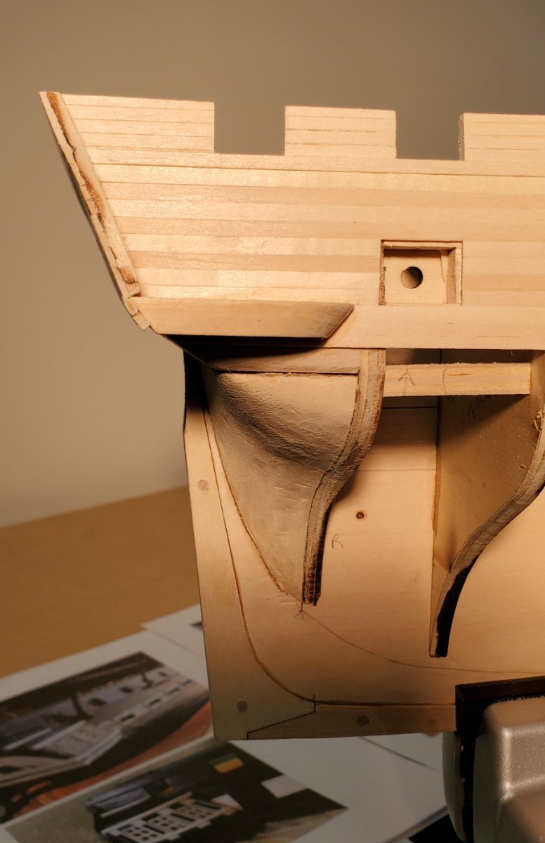
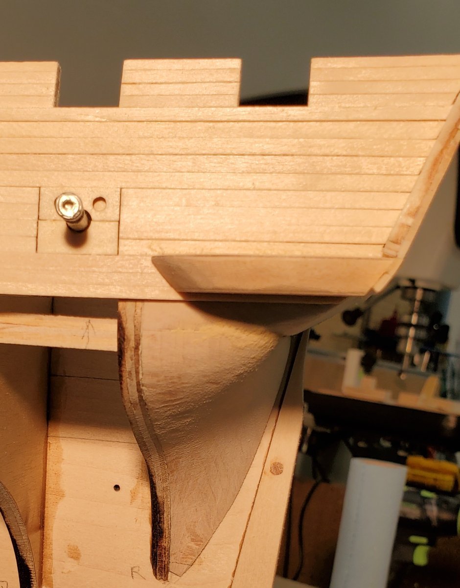
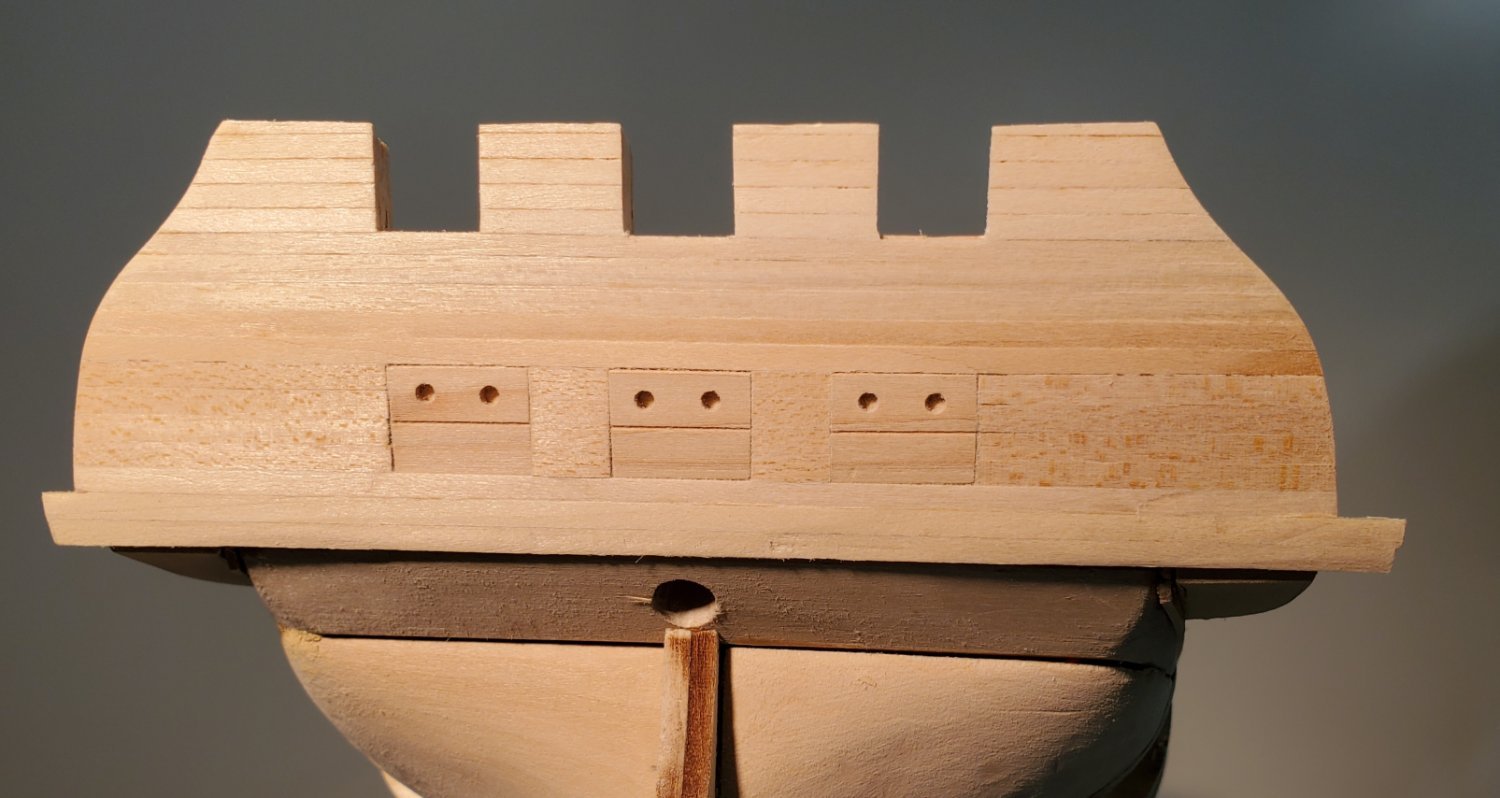
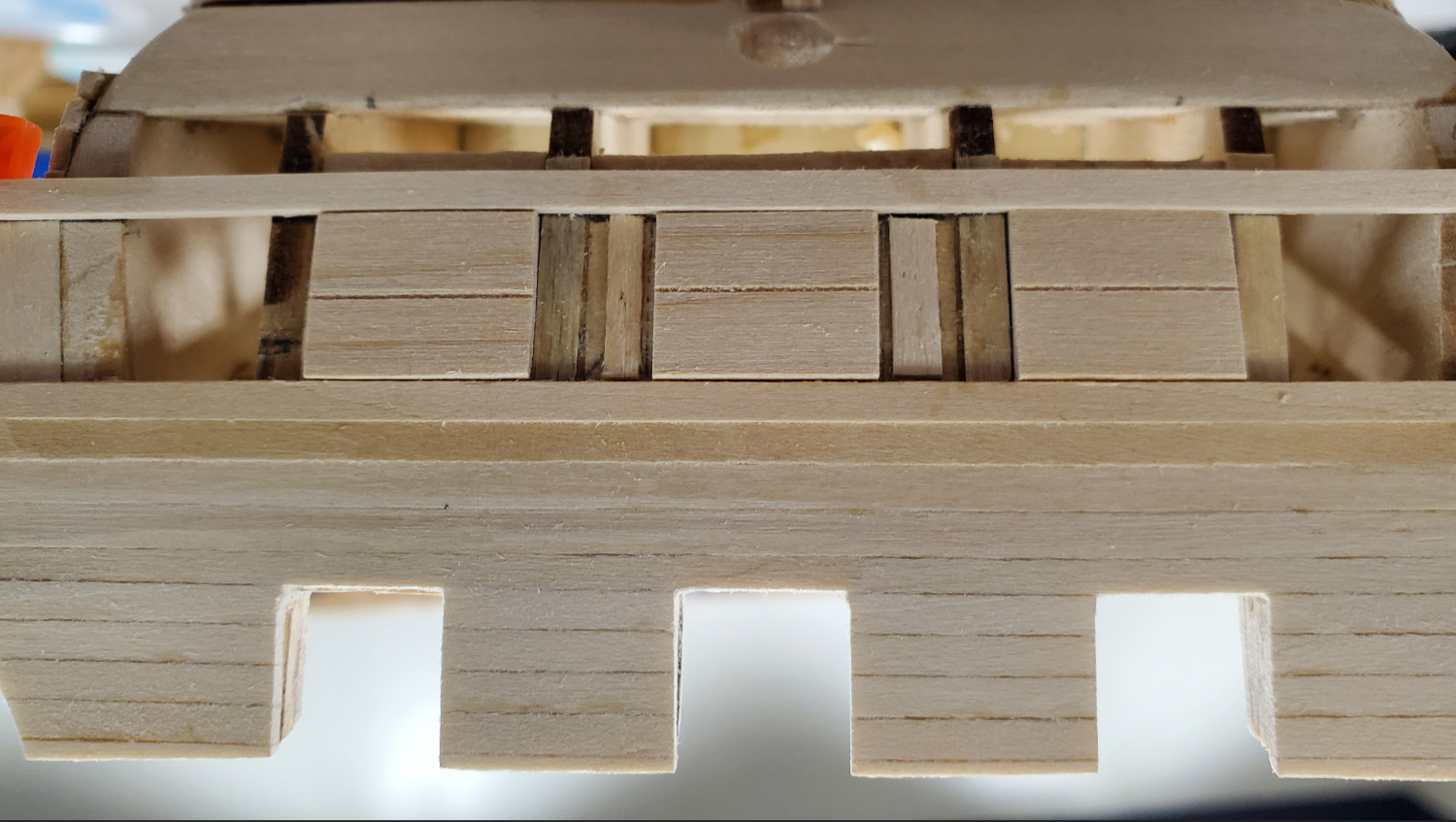
So, in keeping with my switch to filler blocks vs. gunport framing, I added three blocks where the stern gunports should go. In retrospect, I should have made these long enough to touch the counter, but it is what it is.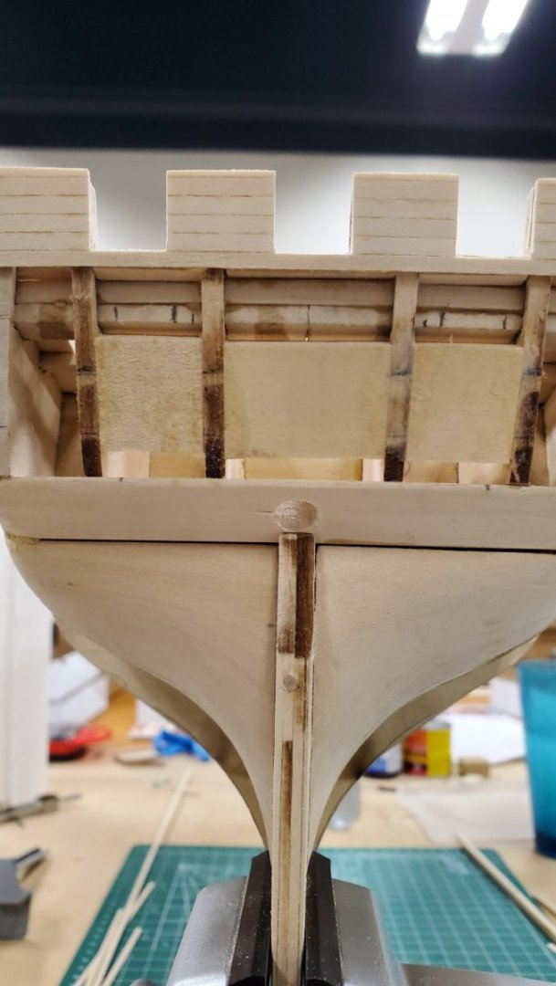
I then made blanks of the gunports so that I could position the plank below the ports – see photos below.
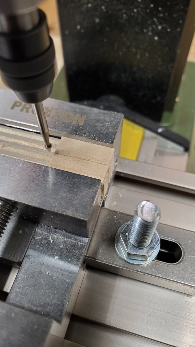
Since I will keep these doors closed, and since there won’t even be a gun sticking out of the port, I opted to dress up the blanks to look like the closed port cover. I made good use of my Proxxon micro mill to carve the horizontal center line simulating where the upper and lower cover meet. Then I positioned the mill to put center marks where the two holes in the upper cover are supposed to be. Finally, I drilled 3/32” holes.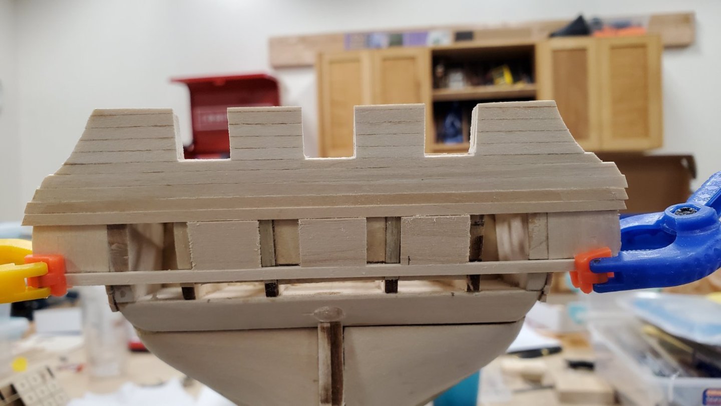
Always looking for a way to use the Proxxon micro mill..

Looking good. (The port covers are not glued in, but man they aren't coming out easily either. May not be a problem? I think I'd like them out when adding hinges later. A problem for another time.)
-
6 hours ago, GGibson said:
Yep! In addition to usedtosail and xken, I also have Modeler12's build log in my list of finished Constitution logs... as well as all of your current build logs to look at.
Oh my! How did I miss that one! Adding it to my list of references. Thanks for the tip
-
On 12/13/2023 at 8:46 PM, kmart said:
Also look up usedtosail finished build log. Its effectively a full blown practicum.
Among finished build logs to consult for inspiration and insight, don't forget XKEN
https://modelshipworld.com/topic/11935-uss-constitution-by-xken-model-shipways-scale-1768/
- GGibson and Geoff Matson
-
2
-
-
20 hours ago, woodartist said:
Particularly in my case because I only have use of one hand and having a stable surface to plank is critical.
I'm only missing the tip of an index finger, and it's been challenging at times to deal with the fine-motor-skill work. I can't imagine doing it with one hand.
Simply amazing.
-
20 hours ago, woodartist said:
I took your little plugs and replicated them, I just started the process of framing the gun ports. So far it is working perfectly.
Glad they're working out for you.
-
10 hours ago, mtbediz said:
It is certainly much easier to do the hull planking with the ship upside down. In all my models, I do not start doing the deck details until the hull planking and copper plating (if necessary) are completed. I even recommend doing the rudder and hinges while the ship is still in an upside down position. It will be much easier.
My thoughts exactly. Glad to have them confirmed by such an accomplished builder. Bottom's Up!


USS Constitution by Der Alte Rentner - Model Shipways - 1/76
in - Kit build logs for subjects built from 1751 - 1800
Posted
That is my plan.
When I return to the shipyard tomorrow, I'm starting the starboard side wale. Now that I know what to keep an eye on, I'll adjust the widths as I add each strake. Since I'm still hopeful of staying with a natural (or lightly stained) wood finish, and since only one side of the model will be facing the room where it will be displayed, I'm thinking I can present the better looking side to the public. And no one but my MSW followers will know the difference.
But I believe I will indeed get to know your best friend very well very soon.. (I've experimented with that nasty bit of carving that will be the lower gallery piece. That may end up simply being formed with filler/putty and possibly covered with thin planking strips)
Thanks again Jon,
Have a great 2024.
P.S. Here's someone who is not starting 2024 off on great footing. Someone left a garage door open and Mr. M tried to raid the shipyard. How he managed to entangle himself on 3 of the 4 traps along the wall remains a mystery.