


64Pacific
-
Posts
51 -
Joined
-
Last visited
Content Type
Profiles
Forums
Gallery
Events
Posts posted by 64Pacific
-
-
Outstanding and inspirational work!
- Keith Black, archjofo, mtaylor and 1 other
-
 4
4
-
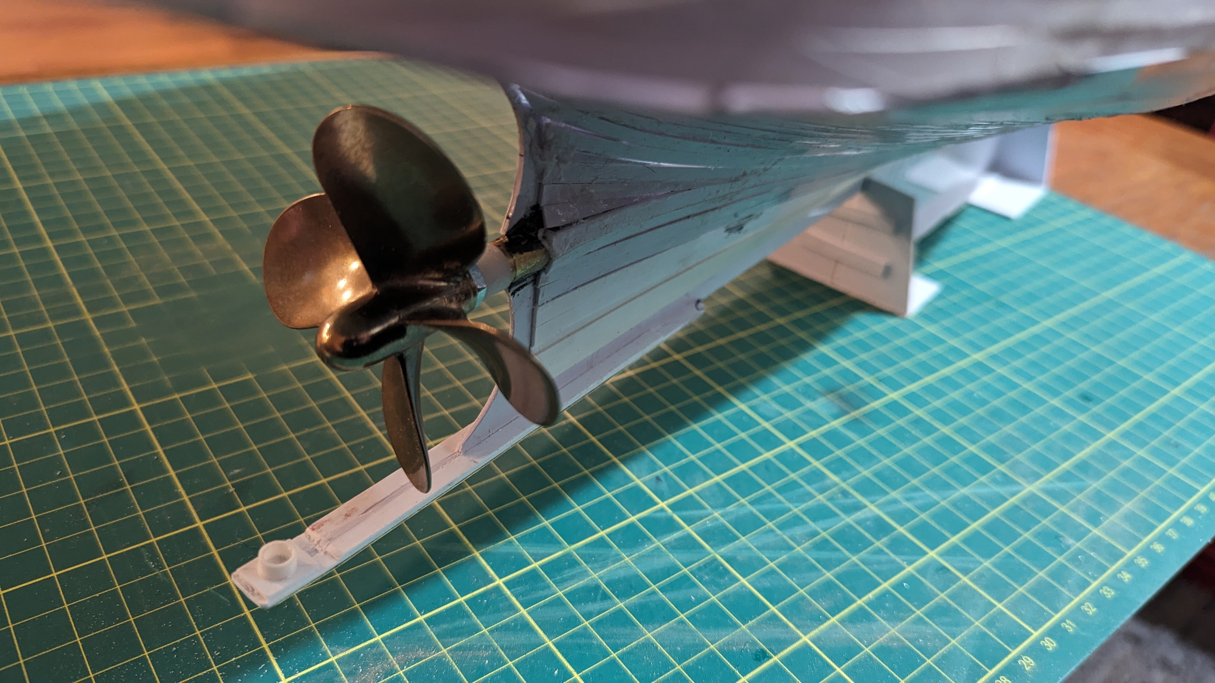
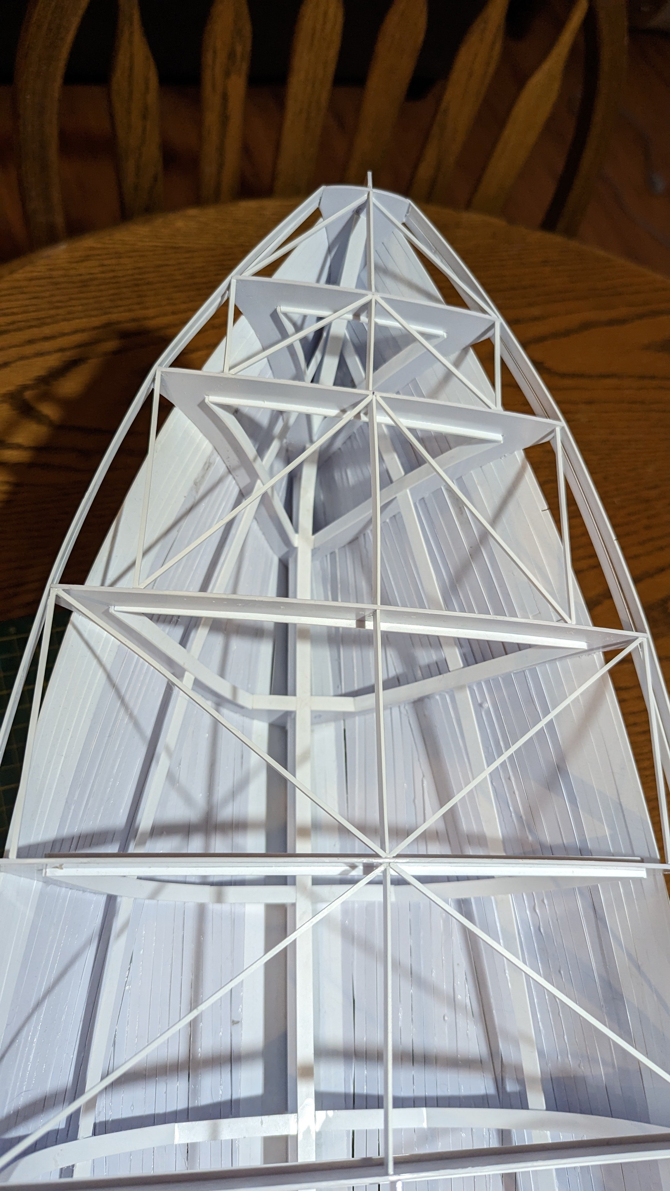
The next step was to build the rudder and shaft, a few shapes were laid out from the drawings, cut and glued. The goal here was to build the rudder as close to the design shown, the correct number of stiffeners using plastic that is as close to scale as possible:
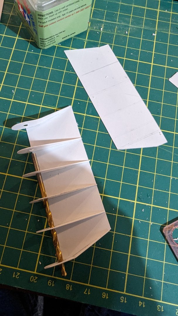
The keel below the rudder was built up per the drawings as well. A strip of brass as glued to the underside to help hold the shape below the rudder:

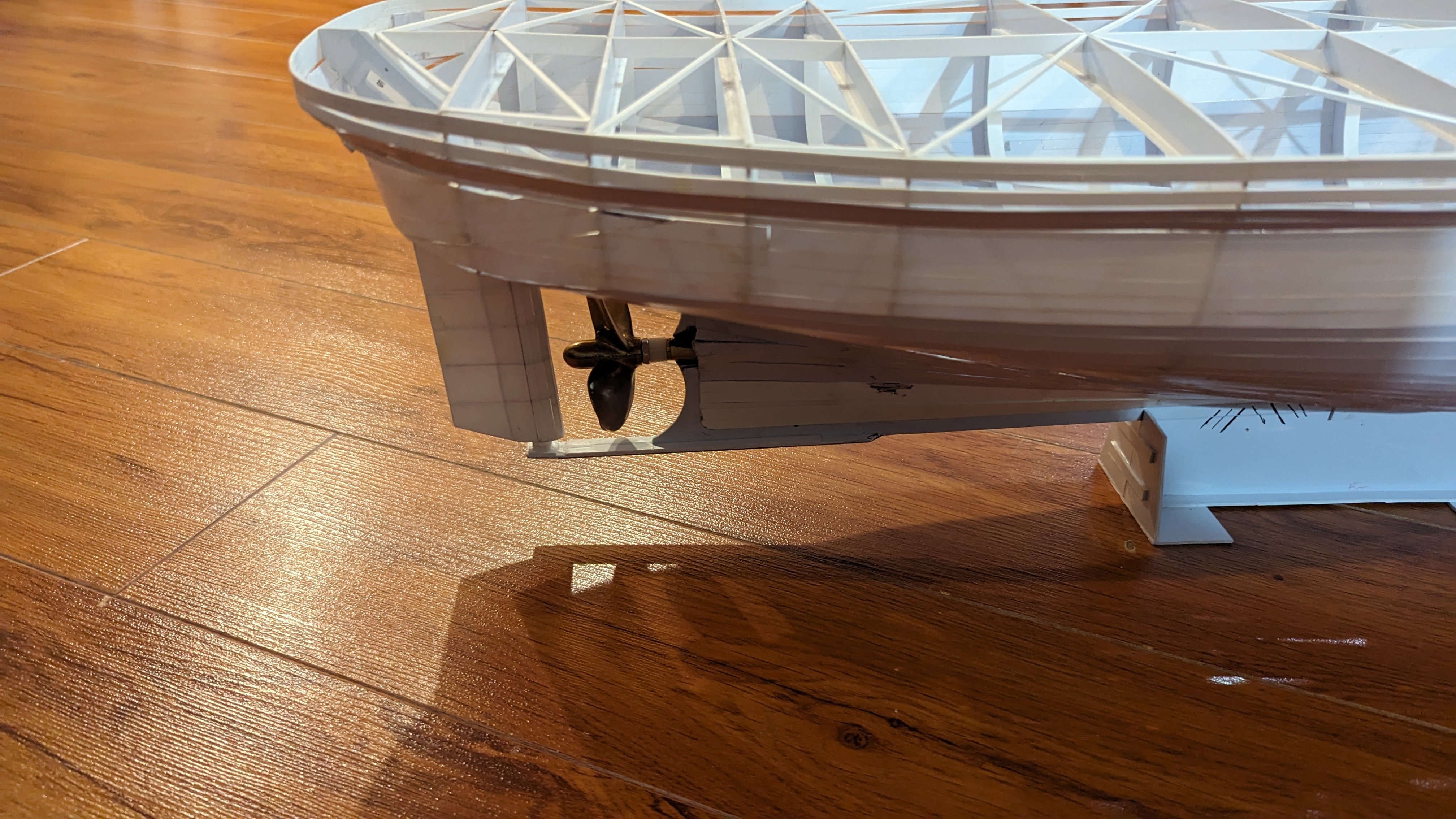
Next using the boss glued to the keel a drill bit was used to align another piece of tubing inserted into a hole crudely cut through the hull. Once the glue set this fixture was used to drill straight through the ribs which would intersect the rudder shaft:

The rudder assembly, a piece of brass rod was chucked into the drill press and small file used to cut a couple o-ring grooves. A piece of 3/16 brake like was cut to length. The brake line would be fixed in the hull and act as a bearing surface for the o-rings. It can't be seen in the photo but the brass shaft is continuous, it will need to be cut in half, keyed and the lower half glued to the inside of the rudder:
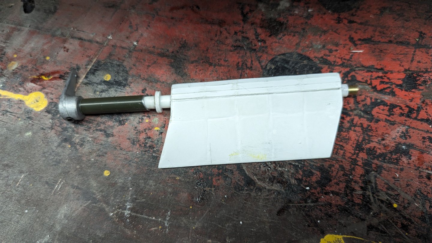
The rudder installed in the hull for a test, it will need to be removed to tidy up the hull. Without the splice in the rudder shaft it has proven quite difficult to remove the rudder without bending the keel. A bit of lube down the hull mounted rudder tube to release the o-rings from the steel brake line should allow me to get the brass rudder shaft out to cut in half.


-
It has been a while since I last updated this thread. There hasn't been a lot of progress lately due to work and trying to get my old logging truck running and painted.
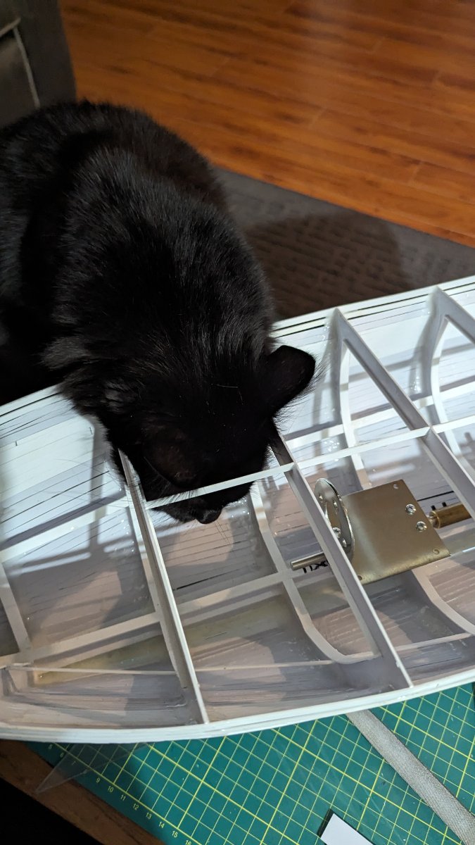
To continue with catching up to my current state on the project here are a few photos of the planking.
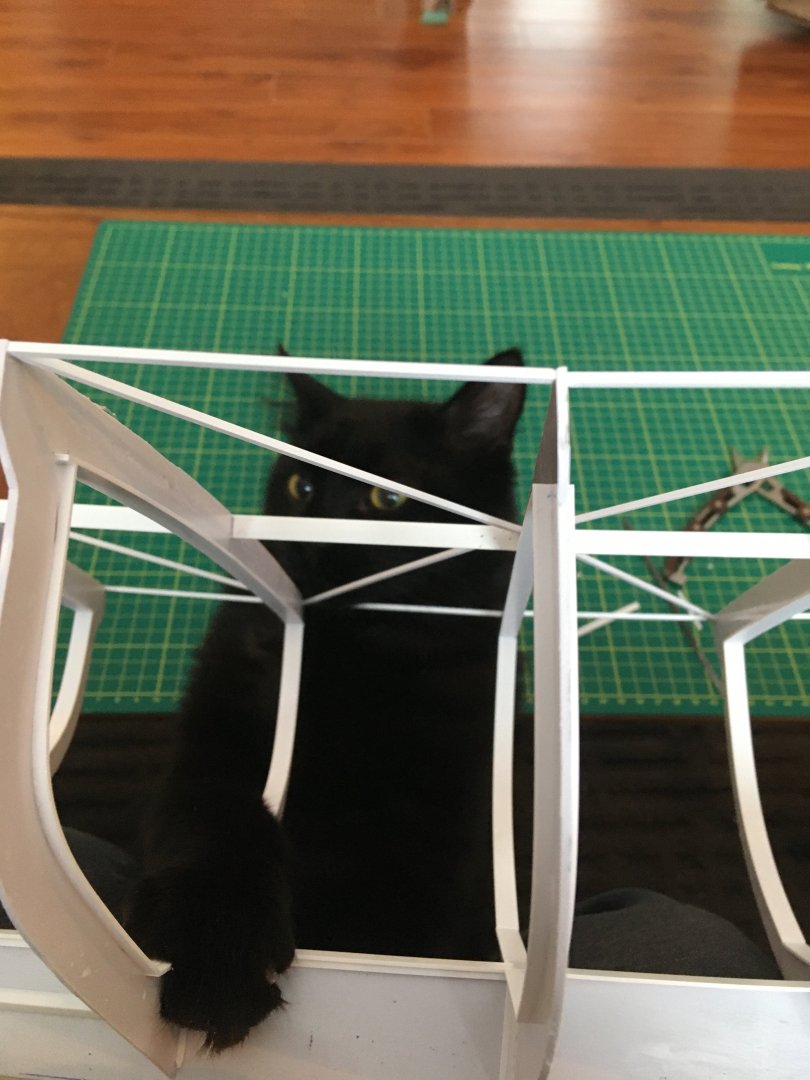
My "helper" adjusting a few parts shortly after removing my first attempt at planking:
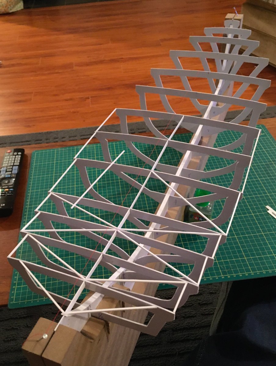
Starting at the keel strips of styrene are being added. My thinking was to start here to reinforce the keel and the joint between the ribs and the keel:
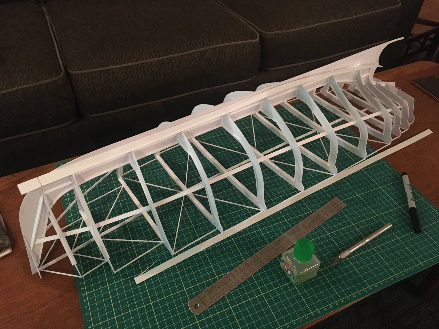
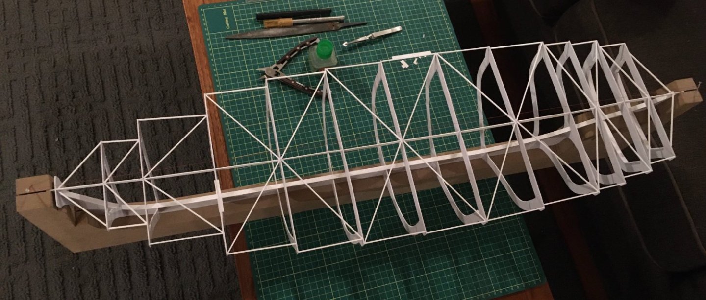
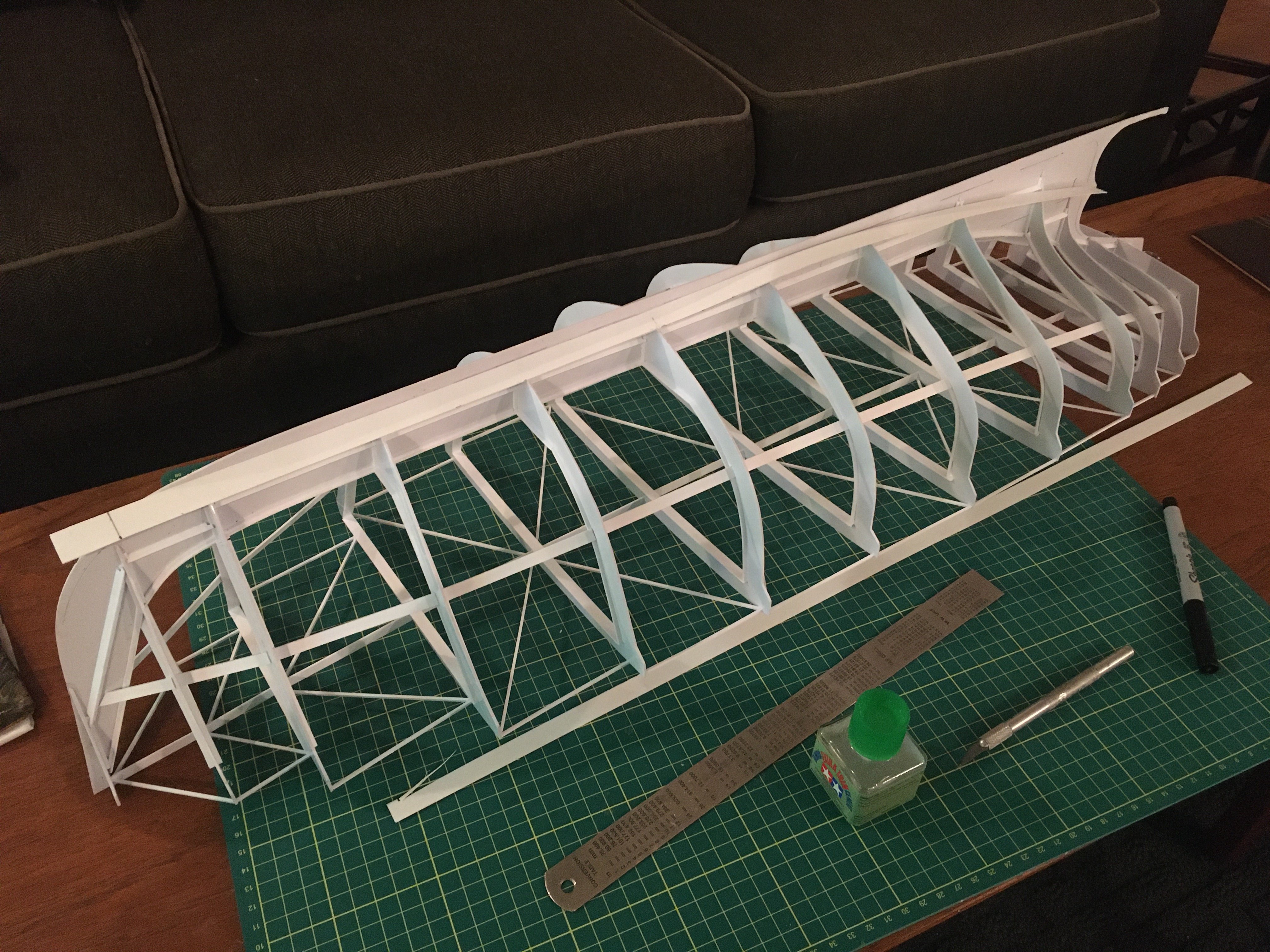
Back into the MDF jig the next strips were added to the top edges of the ribs. A lot of wire and clamps were added to hold everything inline and tight to the ribs a lot of care was taken to ensure that the ribs stayed true and were not twisting as the planks were tied on and fixed with plastic cement:
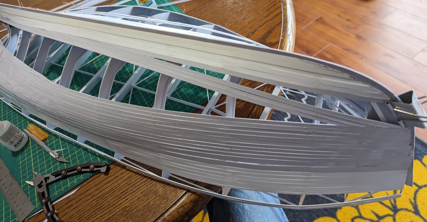
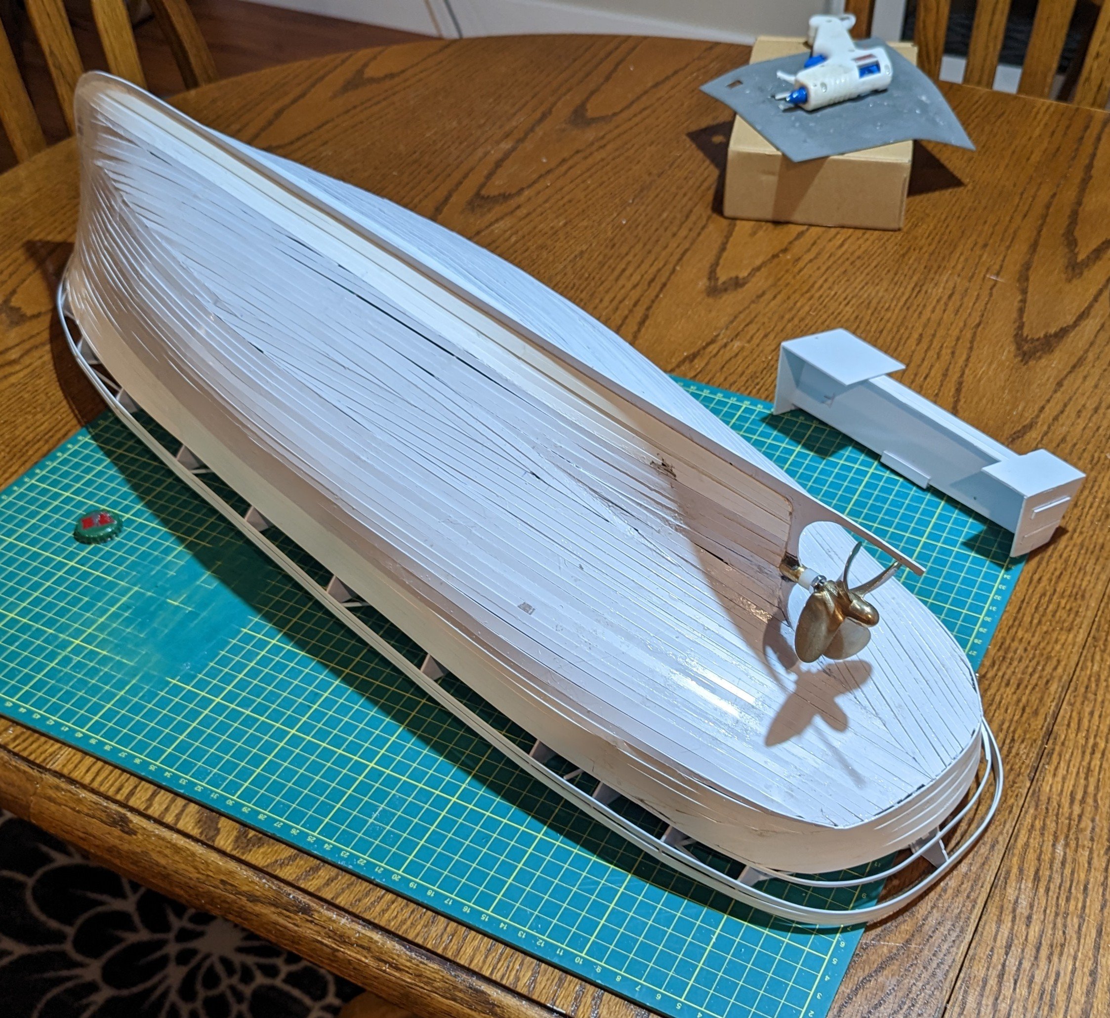
The curves at the stern were a real battle, not quite right but nothing that body filler and fibreglass can't fix. There must be a better way to do this:


-
Hello all,
I am not certain if this is the correct place for such a query, apologies if it is not. I've recently purchased a nice copy of the aforementioned publication, specifically the 1961 edition. On the dust jacket it is noted that there are "drawings and complete working plans for Clipper Ship, a...". In flipping through this book I've seen a lot of nice sketches and drawings but no working plans, or what I would consider working plans. While the book looks complete I am wondering if, or where, in the book one finds these working plans? As an example, on page 285 the book notes under the brief section of "The Monitor and The Merrimac - Folded Plan" but there are no folded plans...
Thanks!
- mtaylor, Scottish Guy and Archi
-
2
-
 1
1
-
On 11/26/2023 at 2:28 PM, vaddoc said:
...
We rarely know what our future holds but mine certainly has a lot of sanding.
Till next time
Vaddoc
This made me chuckle, I am very glad that I am not the only one with a lot of sanding in my future. With my tug model and body work on an old logging truck I am certain that by mid year the sight of sandpaper will make me feel ill!
Great work, another intriguing model build to follow!
- mtaylor and FriedClams
-
2
-
This is really neat, being able to follow along with your build and the rebuild of the prototype. Definitely inspiring but my boat building skills are not there yet...
- FriedClams, Keith Black and FlyingFish
-
3
-
Very interesting project and prototype! Looking forward to following along!
-
A few years ago I was playing with custom white balance, I wanted to see what would happen if I used some colour that wasn't white.Tthe idea was to drastically see the effect as I wasn't sure what was going on. I had a burgundy box in front of me, I found something with a green or cyan tint to it, the greenish colour was used as the white balance set point, it just happened that the colours were roughly opposite one another on the colour wheel. The camera is now trying to adjust for what it thinks is green light removing the green to get to white. With this custom cyan / green white balance I snapped a photo of the burgundy box. The burgundy sections of the box were nearly converted to grey while the colours with less green stayed a little closer to their actual but were tinted with a green hue. It seemed to me that the colour opposite that of the white balance on the colour wheel was essentially removed from the image. It was a really long time ago that I did this so maybe I will try again and post some tests...
-
Nice work, this looks like a really fun build!
I see you that also have a "thinking cat" and an inspector, usually they jump up on my head at precisely the wrong time!

- GrandpaPhil and mtaylor
-
2
-
-
Definitely go with what Ron is saying. For my last build (primarily for Siemens Solid Edge) I bought the fastest (per core) processor that I could afford, substituting quantity of cores for speed. The other consideration is graphics hardware. While there is a hefty price difference you will notice a significant speed and stability increase when using professional grade hardware. Gaming graphics, while powerful have different architecture and 3D CAD software is not optimized for this architecture. All of that said, probably the biggest and most inexpensive upgrade that you can make for a 3D CAD machine is an SSD followed by a lot of fast RAM.
- thibaultron and mtaylor
-
2
-
I think that the timber joints on this model are built to a tighter tolerance than the original ship, spectacular work!
- Keith Black and mtaylor
-
2
-
Quite an interesting project and a great read on a quiet Sunday morning. Nice work, looking forward to watching this one continue along.
- Reverend Colonel and mtaylor
-
1
-
 1
1
-
The wife's Cricut was a huge timesaver when laying out the keel and cross sections for my tug build. Definitely not the classic way of doing things but it was hard to argue with the ease and quality of the results.
As far as using non-modeling tools for modeling, sewing needles came to the rescue on a scratch built logging truck that I was building years ago (and finished recently). I needed a way to connect the front tires to the front axle while allowing the front tires to steer. I happened to mention this to a seamstress and she suggested cutting down a standard sewing needle. The flare from the cut down eye was enough to hold the needle in a short tube and the cut down end of the needle passed through the tube and nicely into the wheel, the tube was fixed to a pin and linkage to allow the wheels to steer. This was about twenty years ago, I wish that I could find her to say thank you and let her know how it worked out, but I have no way of finding her...
- mtaylor, Ras Ambrioso, GrandpaPhil and 1 other
-
4
-
Very nice work, looking forward to watching this one progress.
- Louie da fly, mtaylor and Canute
-
2
-
1
-
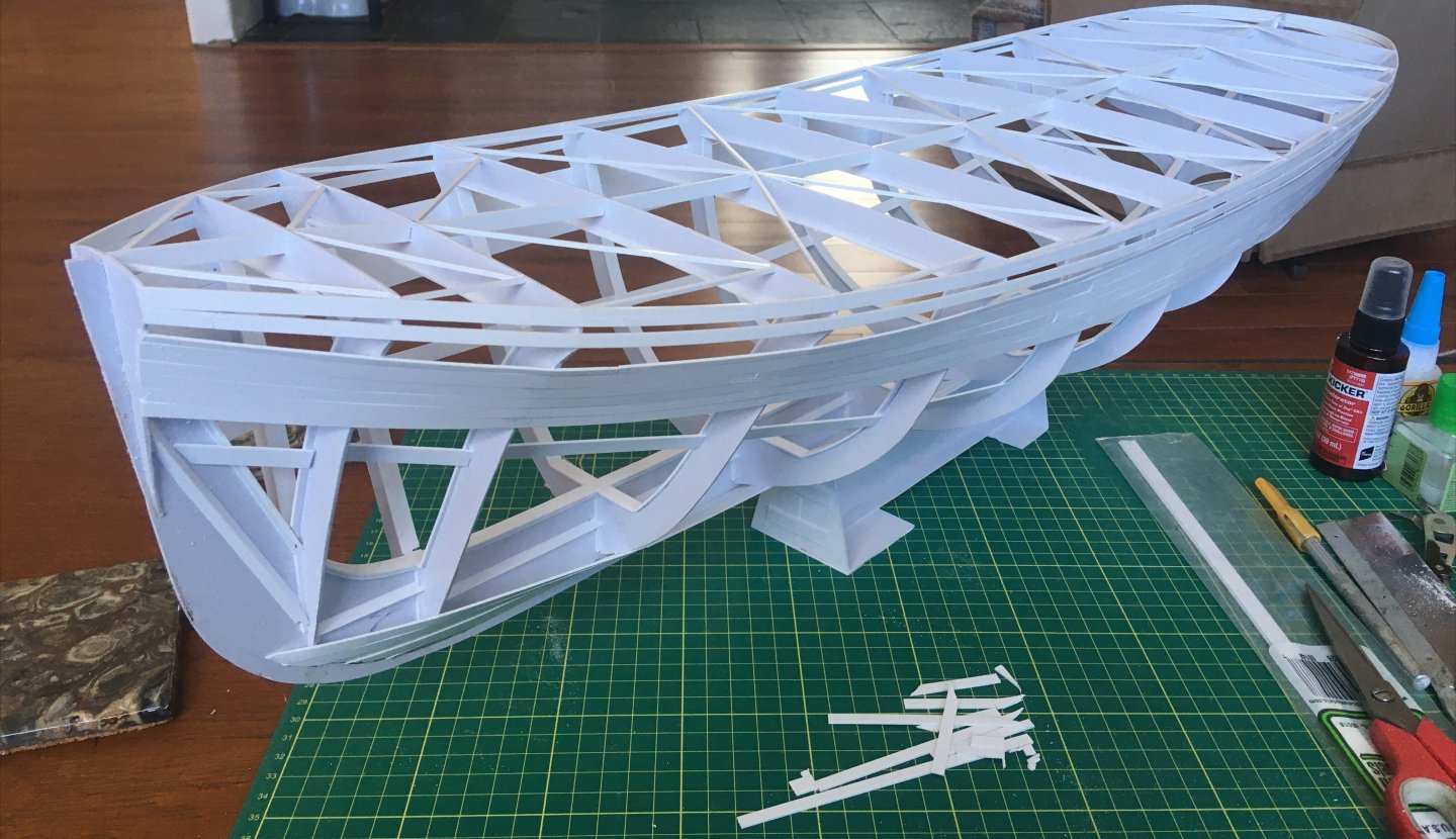
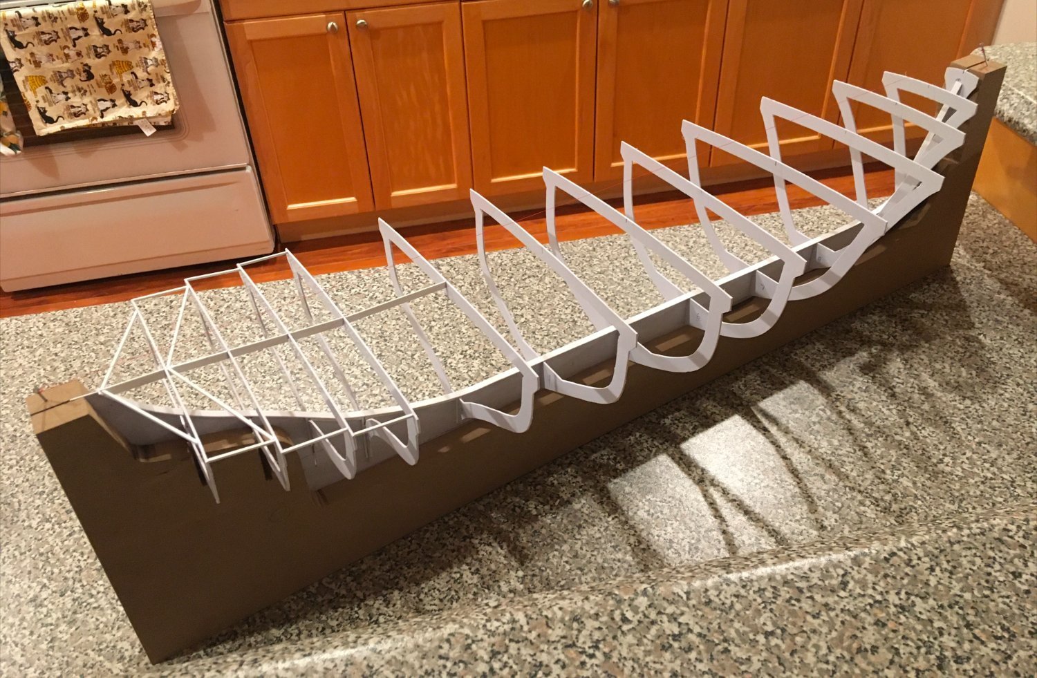
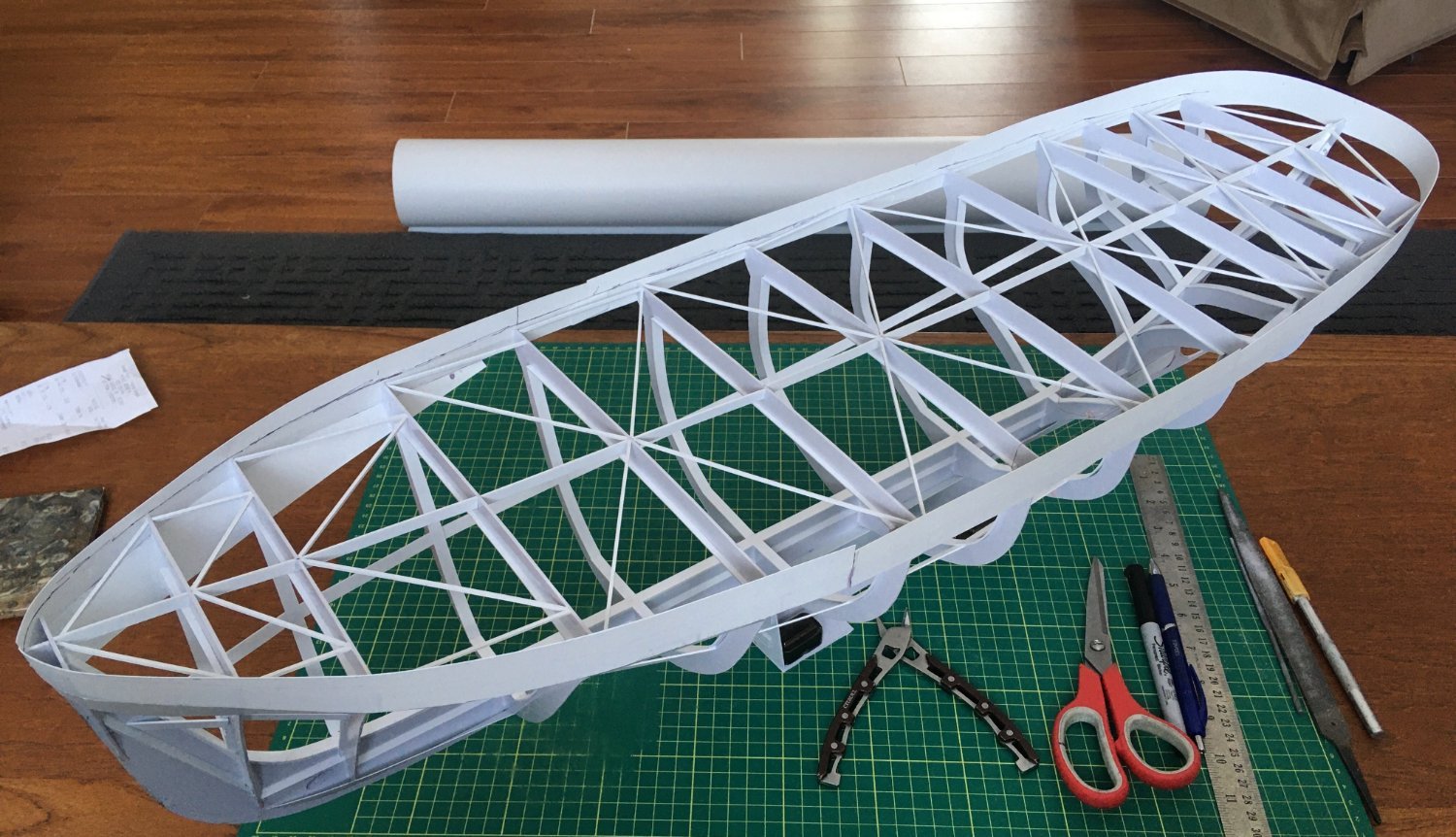
The next step after inserting, but not fixing the ribs to the keel was to start the process of reinforcing the keel. This may have been unnecessary but my thought was rigidity would be an asset, especially when the model was removed from the fixture to begin the process of planking the hull. To do this strips of plastic were added along the length of the keel. Also at this point a stand was built using scraps.
.thumb.jpg.310f97bdf7b8240283f31cf065a02893.jpg)
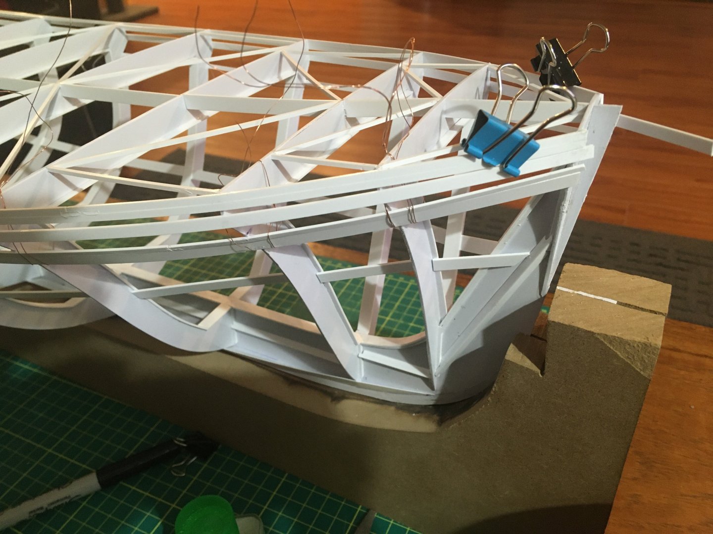
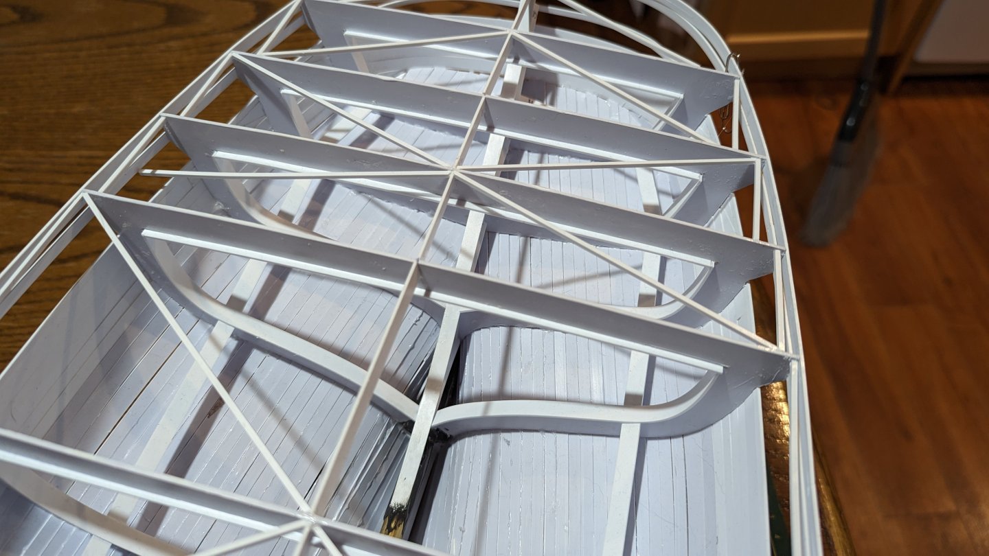
Following this and starting at the bow each rib was squared to the keel and to the bench prior to being fixed. Temporary light bracing was then added after carefully measuring to ensure that the ribs remained perpendicular to the keel and parallel to each other. This step took forever, it was measure six times then glue.


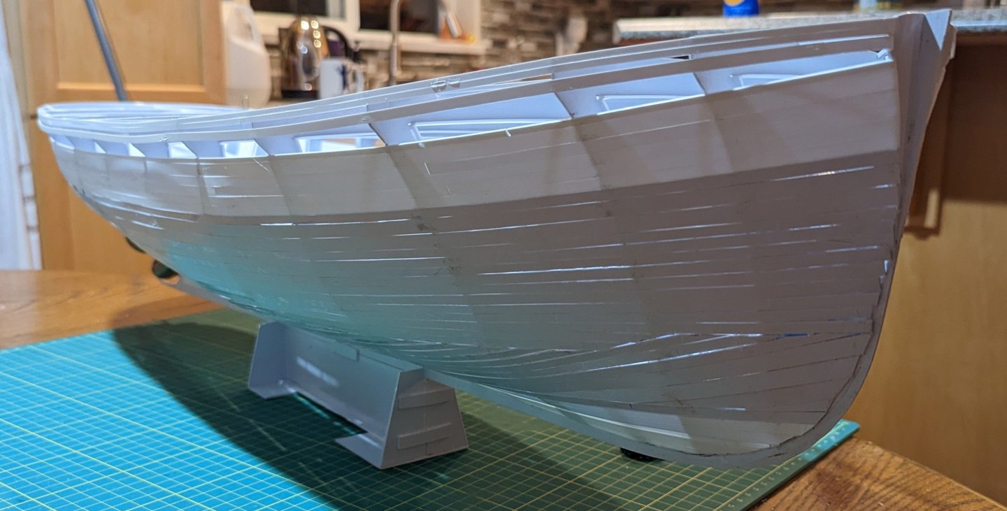
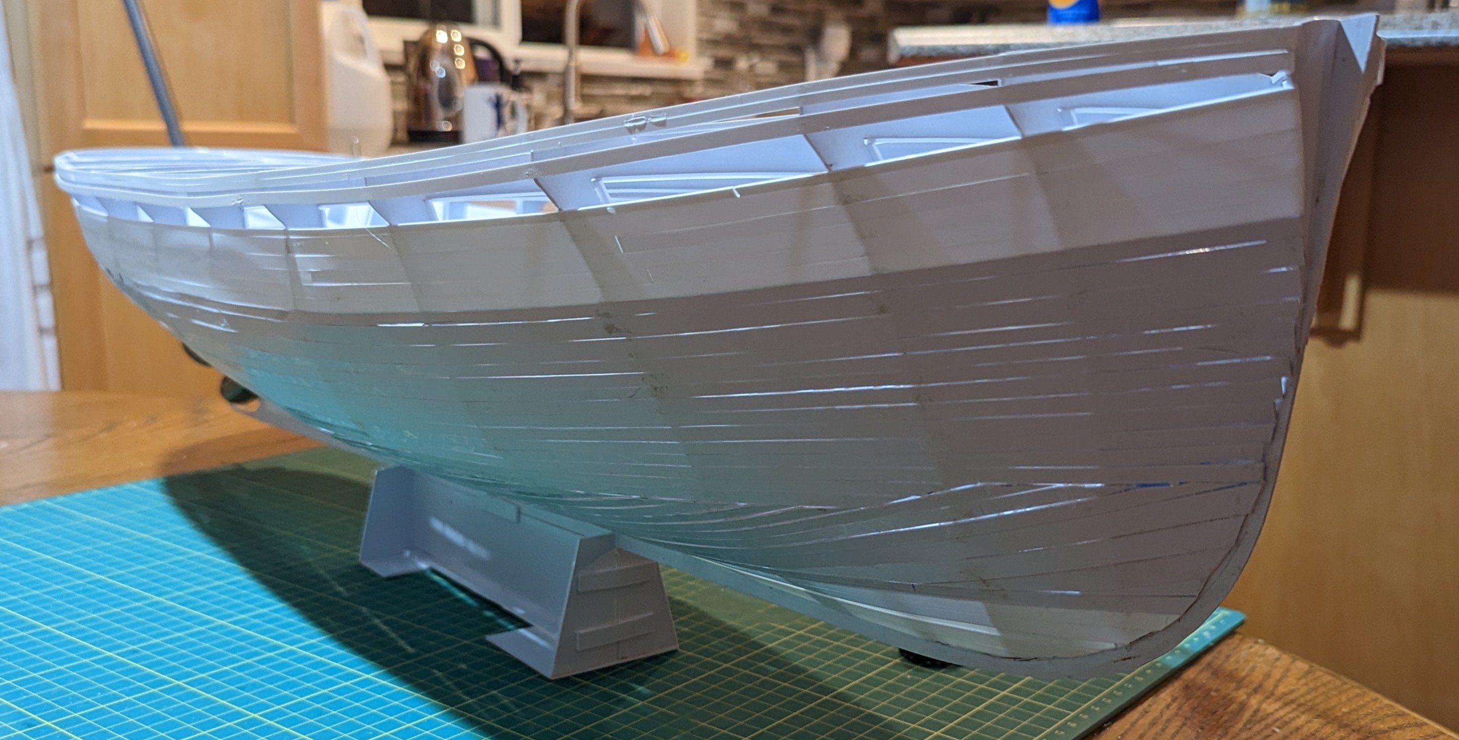
More bracing on the inside of the ribs and the face of the keel. Some of the planking was being added here. Initially the plan was to roughly skin the model and then apply a second layer. This strategy was soon abandoned in favour of one layer of thicker planking.
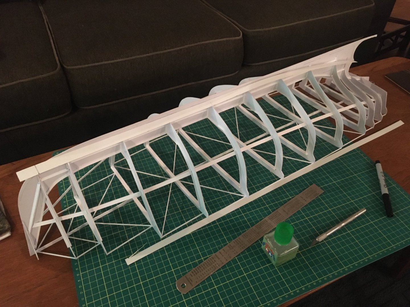
Once some planking was added at the keel I jumped up to the top of the hull. While I was happy with the shape of this upper planking my process of installing the planking and then trimming to be flush with the deck proved to be too difficult. This was later stripped off.

-
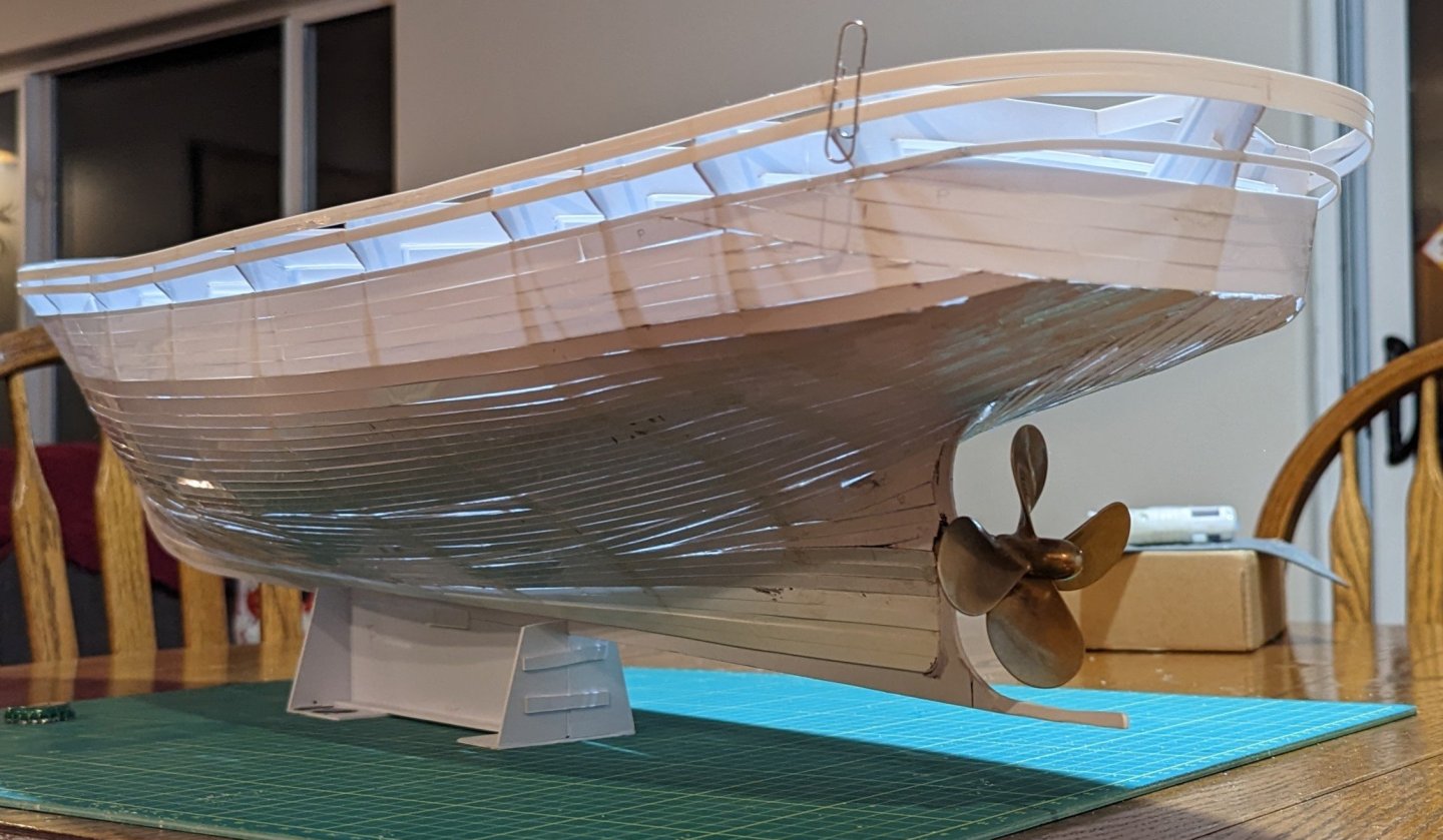
Keeping the water out is probably one of my biggest concerns, visions of the tug sinking have definitely crossed my mind! With a combination of fibreglass resin and body filler I should have a good chance of keeping it out of Davey Jones' Locker!
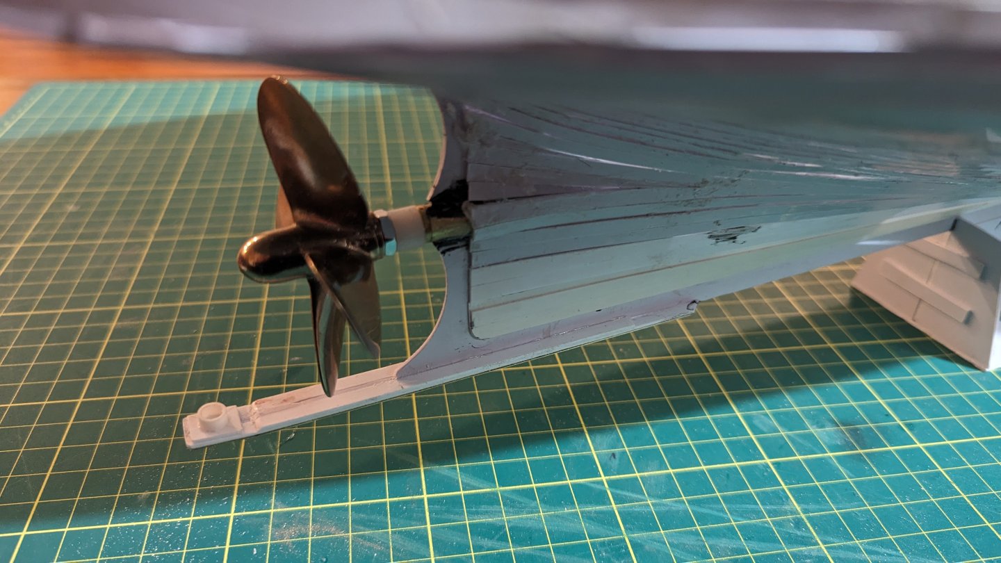
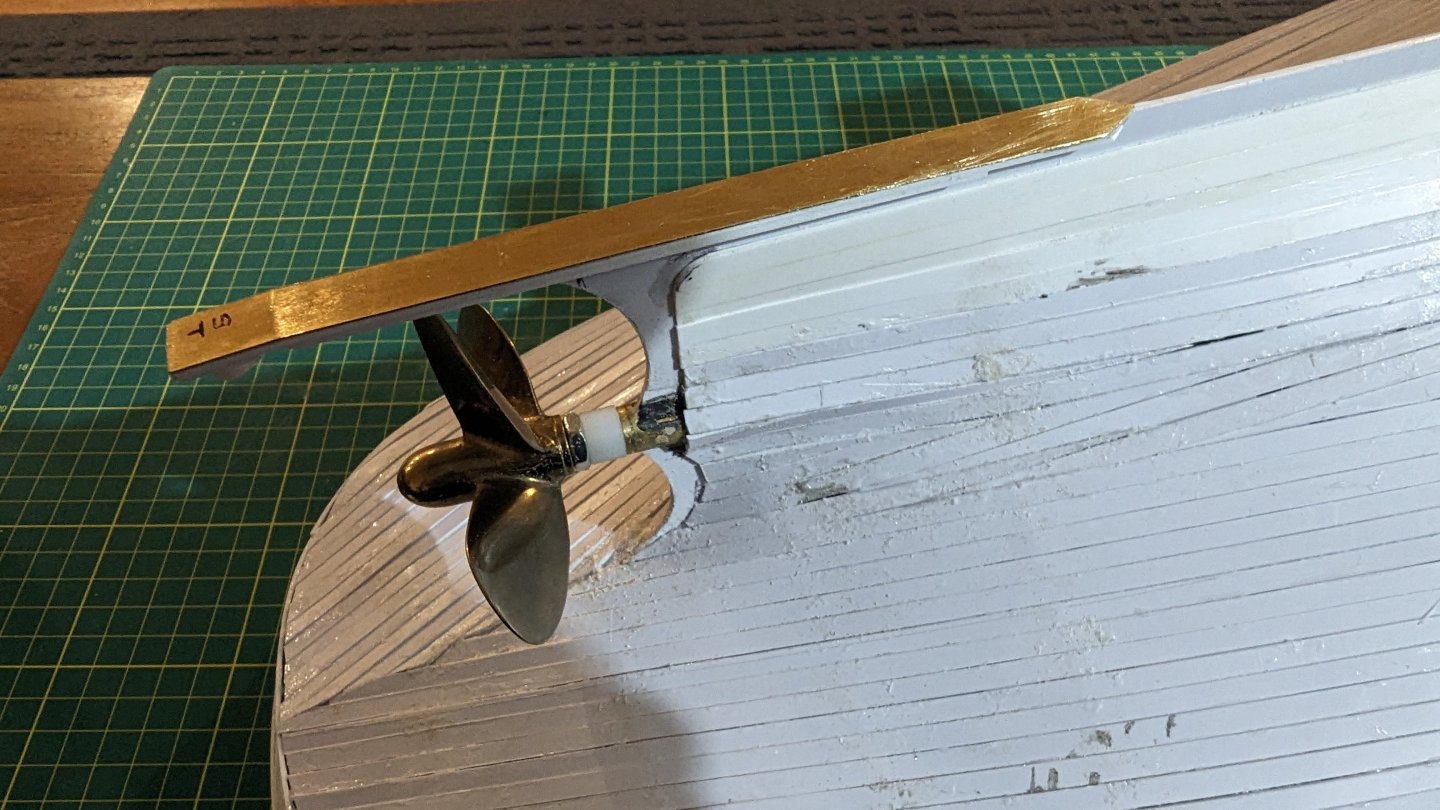
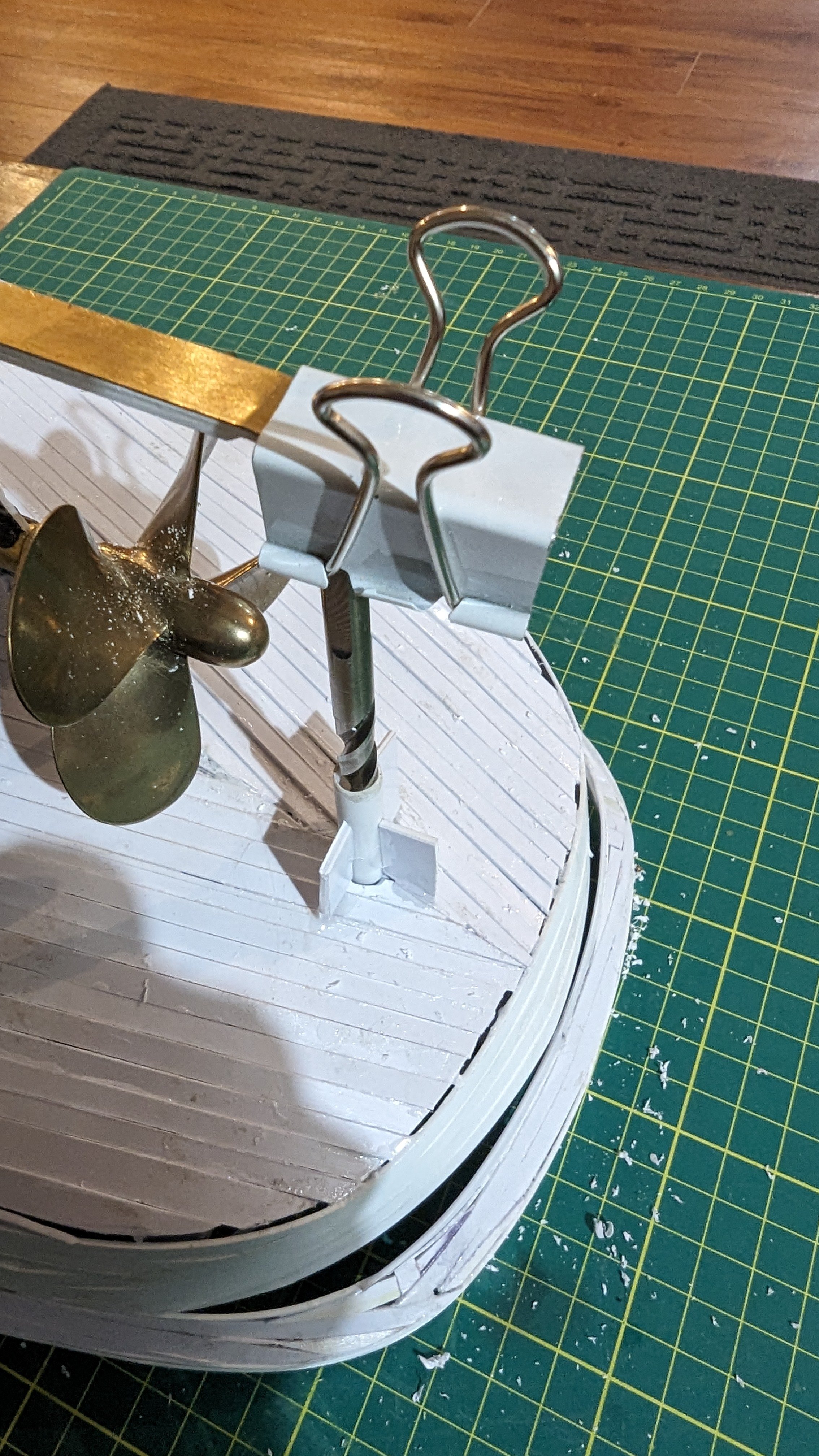
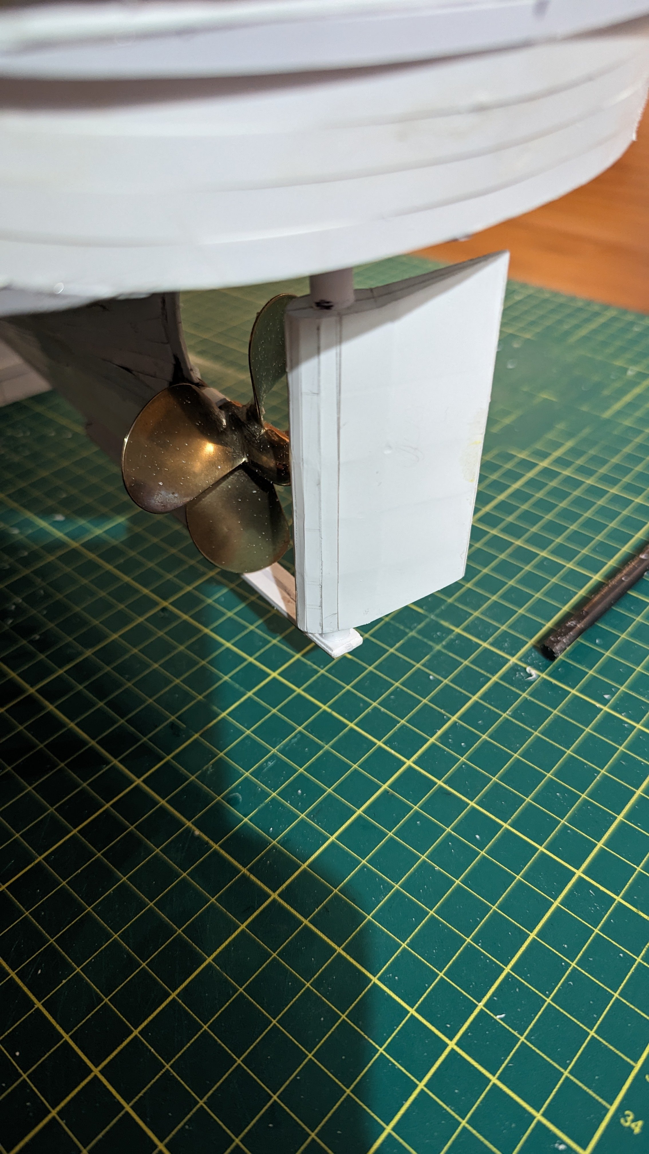
Initially there was no plan to install the prop. shaft, or any of the RC gear for that matter. Once the shaft arrived a jig was designed and 3D printed. This jig, complete with an appropriately sized hole was slipped over the keel, the hole was sized to accept a drill bit. Nervously but without hesitation a 3/8" diameter hole was bored into the keel and through the ribs. Following a bit of minor filling the stuffing box was inserted and fixed with JB Weld, this epoxy was used as it is what was handy in the shop. I believe that in my nervous state no photos were snapped of the jig on the model or in use, I will however post a few screen shots of it in the slicer.
-
Welcome, and that is a great looking model! The HMS Prince looks like an intimidating ship, both to have seen on the seas all those years ago and to model, wow.
- mtaylor, Keith Black and Nica21
-
3
-
Thanks Guy. Now that the weather is turning I am getting really excited to get the hull done and into the pond for a test, a few weeks and it should be ice free. Hopefully at that time the hull will be done. Maybe tonight I will find some time to update the thread with some shots of the next steps...
That is a great looking tug that you served on, very classic lines. I am sure that you have some interesting stories of life aboard.
-
Very cool project!
- FriedClams, Canute and mtaylor
-
3
-
On 3/14/2024 at 8:44 AM, allanyed said:
64
I did a couple desk top Armstrong Fredericks in 1:24 and it made for a nice change of pace type project. Give a shout if you want the carriage drawing.
Allan
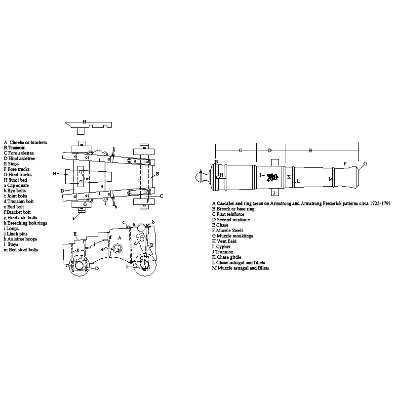
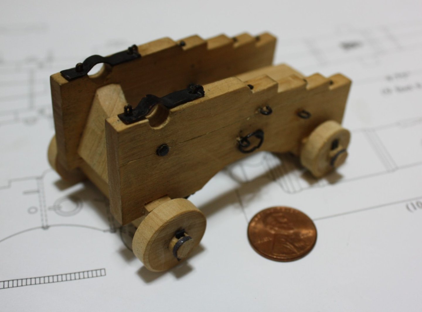
Thank you for the offer, I will try to send you a message... Your cannon looks really great, it looks like it will be a fun project and a nice break from my plastic tug and old rusty truck.
- mtaylor, thibaultron and Tim W
-
3
-
Looks like a nice model, and some really nice work. Have you made progress on the model since your last post?
- mtaylor, Canute and Mirabell61
-
3
-
Incredible! Just had a quick browse through but will have to read in detail.
- Canute, mtaylor and Keith Black
-
3
-
Impressive work, the piping looks great!
- Glen McGuire, mtaylor and Canute
-
3


.jpg.b43a9413052ae9c5210f6a89293d0b40.jpg)


Malaspina Straits by 64Pacific - 1:24 - PLASTIC - RADIO
in - Build logs for subjects built 1901 - Present Day
Posted
It's time that I update this thread and carry on where I left off some time ago. Currently the project is in a bit of a holding pattern, while still on the books it had to take a back seat to my logging truck rebuild, work and a few other things requiring my time; not a lot has happened in the last 14 months. However prior to this hiatus the project did see its first water test, one which turned out much better than anticipated.
To carry on from my last post work was done to mount the motor and steering gear inside the hull:
With this done, the next step for was to do a bit of experimenting. A concern was the adhesion of body filler, styrene plastic and fibreglass and it's differing rates of expansion when subjected to extreme temperature swings. As luck would have it, we were expecting to see -45C in the coming weeks so a few test rigs were made. These rigs had a defined profile, one that I could compare to a go / no-go gauge and mimicked my hull construction. One was lined with fibreglass mat and body filler applied over this and the other smoothed with filler and then covered with fibreglass mat. Once the fibreglass and body filler were cured and sanded these two rigs were toss out into a snowbank to freeze. After a week they were brought into the house, twisted, dropped and kicked and then placed near the toasty warm wood stove. With a temperature swings of about 70 degrees no distortion or separation was noted; both good news for my logging truck and the tug.
Here are the rigs after their torture in the cold, they aren't pretty:
I am not too sure which route to go for glassing the hill. With body filler over the glass sanding is a breeze, however body filler will absorb water over time and any scratches in the paint system may allow this to occur. With glass over body filler sanding will be a bit more tedious but the hull less susceptible to damage. In regards to strength, I believe both to be roughly the same strength, what are your thoughts?