


yvesvidal
-
Posts
3,083 -
Joined
-
Last visited
Content Type
Profiles
Forums
Gallery
Events
Posts posted by yvesvidal
-
-
Here are the promised pictures.
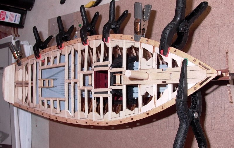
Both covering boards are placed carefully and secured locally (bow and stern) with a dab of CA glue. Then white glue is spread carefully between frames, covering boards and clamps, to make a very sturdy and solid assembly.
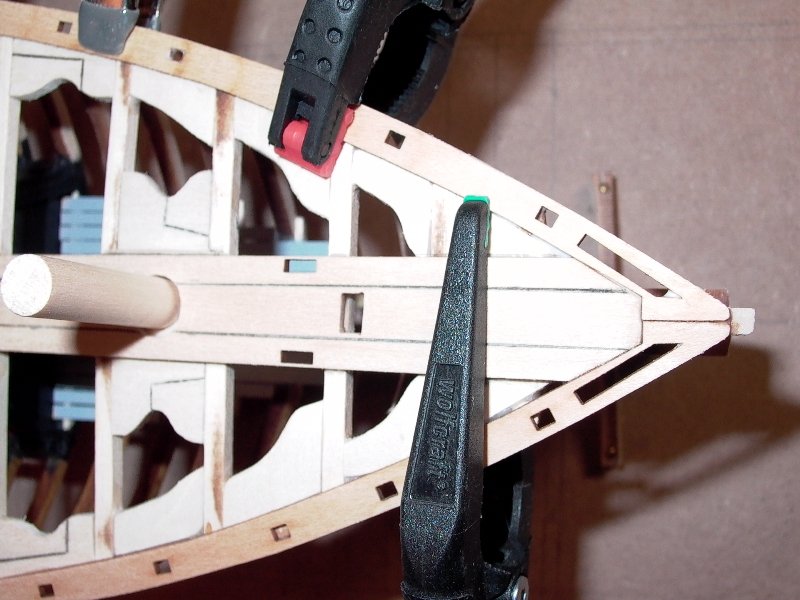
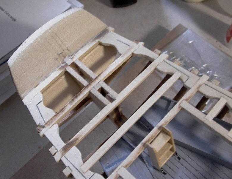
Detail of the bow showing how the king plank helps position exactly the two covering boards:
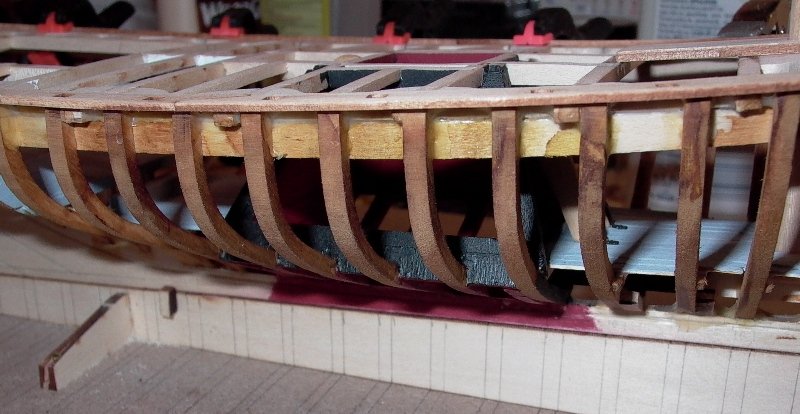
As indicated before, the frames have been sanded and faired, and stained in their visible section with Micro-Mark alcohol based brown stain:
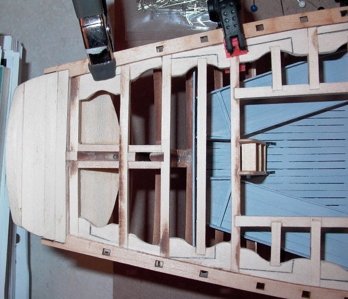
Finally, a close-up on the stern, showing the planking:
That concludes Step 12 of the Stage 1 of the construction. I may stop here for a while as I have other (unrelated to ship models) projects to tackle and finish (electronic designs, home repairs and improvements....etc). It may be weeks, but that should allow the other Emma Berry participants to catch up and pass me.
Thanks for your attention.
Yves
- canoe21, GrandpaPhil, Duanelaker and 1 other
-
 4
4
-
In MSW incarnation #1, there was a few threads about the work of Master modeler Chris Watton and some upcoming kits that he was designing for Amati.
I was wondering if there is anything new in that direction. I remember very vividly two gorgeous models in preparation for Amati:
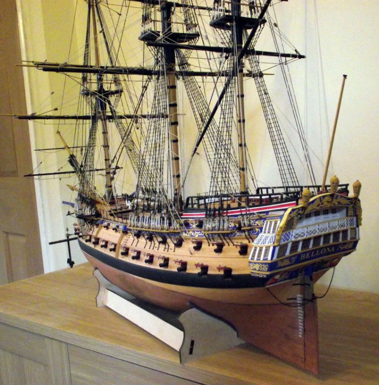
1) The Bellona (unfortunately at the scale of 1/72 - I wish it would be available at 1/64th))
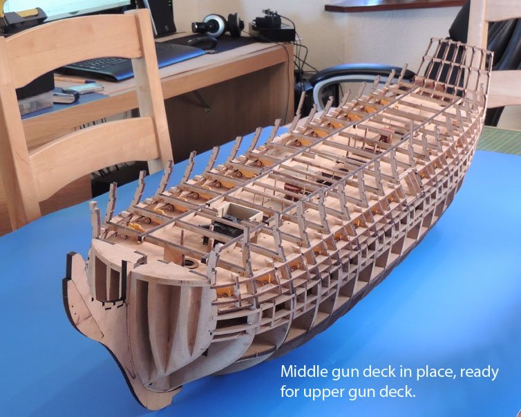
2) The HMS Victory at 1/64th, using a new technique based on MDF for the building of the hull and inner decks.
Could anybody shed some light on these two kits?
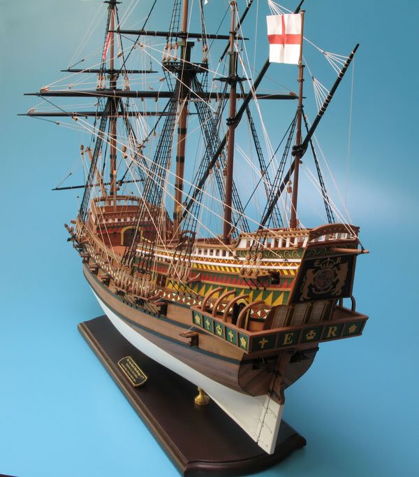
And then of course, there was also the Revenge:
Thanks in advance.
Yves
- Old Sea Dog, biff, dgbot and 5 others
-
8
-
Quick update for tonight. Pictures will come later.
I have started assembling the covering boards which are the foundation plates for the bulwarks. The two halves are assembled using CA glue. It will be necessary to fine tune the cut at the stern so as to be as close as possible to the shape of the transom.
Before gluing the covering boards, it is imperative to:
1) Fair the hull as much as possible. The part located near the deck must be as smooth as possible as it will be tricky to fair the hull when the covering boards are installed. Most likely they will get damaged in the process.
2) Smooth the deck beams, carlings and knees and make sure that the convex shape of the deck (port to starboard) is finely obtained and to your liking.
3) Have the king plank in place and the mast and bowsprit pawl-bit inserted to verify the proper alignment of the plank.
When satisfied, the covering boards can be glued. I decide to glue them one at a time using CA glue in a couple of points to position them and later on soaking the boards, knees and clamps with white glue that will be absorbed by the wood for a stronger bond.
When gluing the covering boards, make sure that the outside edge of the stanchion holes are flush with the outside edge of the frames.
The covering boards are left like this, until the hull is fully planked and the bulwarks built up. Later on, they will be sanded flush.
Some of the stanchion holes are conflicting with the frames and we will deal with those on a case by case. It is expected.
This completes the so called "STAGE 1" of the Model Shipways booklet.
Yves
-
From now on, I am slightly diverging from the Model Shipways instructions. We are now at the stage where the covering boards must be installed (Step 12 of Phase 1 in the instruction booklet).
These covering boards must be glued together (front and rear). When secured, they must be installed on each side of the boat.
I am not sure how this can be done without glueing the Kingplank first. As a matter of fact, both covering boards are resting at the tip of the bow, on the special cut of the kingplank. Therefore, I decided to install the kingplank, before moving to any covering boards installation.
In the previous steps, we had prepared the main mast and the bowsprit holder. These two parts will be necessary to position perfectly the kingplank. Before glueing it, the kingplank will be scribed as if there was a main plank in the middle and one smaller plank on each side (size is identical to the strips used to plank the remainder of the deck).
It may be necessary to soak in warm water the kingplank, which must be bent quite a lot, to embrace the curvature of the front deck.
Prior to this (and it could be done afterwards), I have faired the hull entirely. Then the visible (through the opening I am planning to leave) frames have been stained with a brown alcohol based color (Micro Mark and also available from a Canadian reseller).
It is of utmost importance to fair the hull before glueing the covering boards as these are slightly wider than the hull and will be sanded at the end after the hull has been fully planked. If you try to fair the hull, after having glued the covering boards, you may damage these delicate boards inadvertently.
See you soon.
Yves
- canoe21, GrandpaPhil, Cannon Fodder and 1 other
-
4
-
Thank you Craig. You may actually catch up with me at some time, as I am not very fast and have no more than 15 to 20 minutes per day to dedicate to this build.
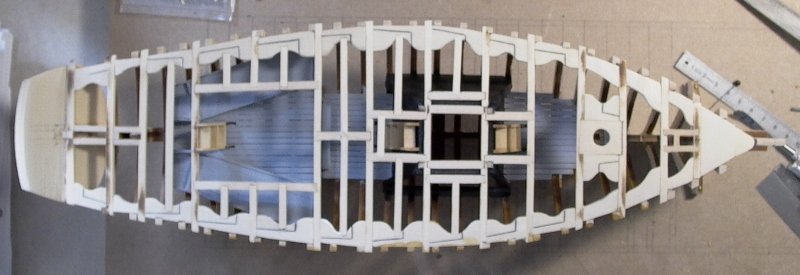
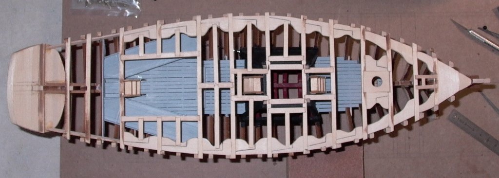
Anyway, I finished the stern and here is again a full picture of the craft showing the intricacies of the beams and carlings. Quite beautiful, I must say (Hey, it is okay to be happy and proud of what we are doing....):
A close up on the stern. The rudder axle box has been completed and sanded flush with the rest of the deck:
Although, the plan does not mention anything about it (or I could not find it), the inside of the transom is planked on the real boat. Therefore, we are going to plank it as well. I am leaving a small gap between the last deck beam and the planking to insert the little strips that will be used to plank the deck:
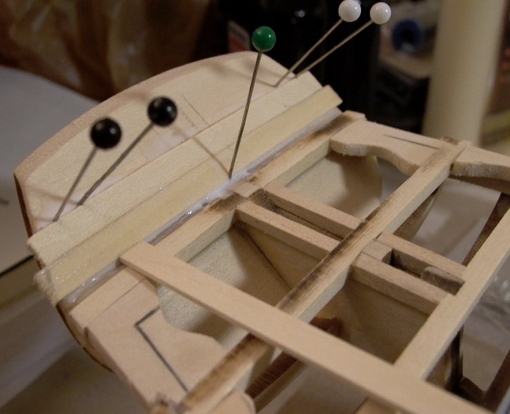
The transom planks have been soaked in warm water to ease their bending. The central pins are pushing upwards, whereas the side pins are giving some curvatures to the planks. We are almost finished:
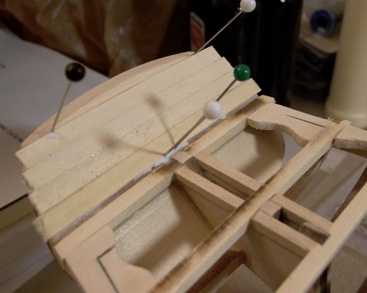
A little clean up of the excess of white glue in the groove seems like a good idea, before it dries. The outside part of the transom will be planked as well, as is the real boat. This will be for a next and upcoming installment of our Emma C Berry saga in ten zillions parts.
Yves
- GrandpaPhil, Dubz, trippwj and 2 others
-
5
-
-
Craig,
Welcome to the world of Emma C Berry. It is actually exciting and stimulating to have currently three persons building the same ship: Don Farr, yourself and me. There may be others, but they did not make it public yet.
It is true that the building of the frames must be made carefully. Assemble each frame independently, and glue the floor every time one frame has it.
Then use the jig to position each frame one at a time, starting from the bow all the way to the stern.
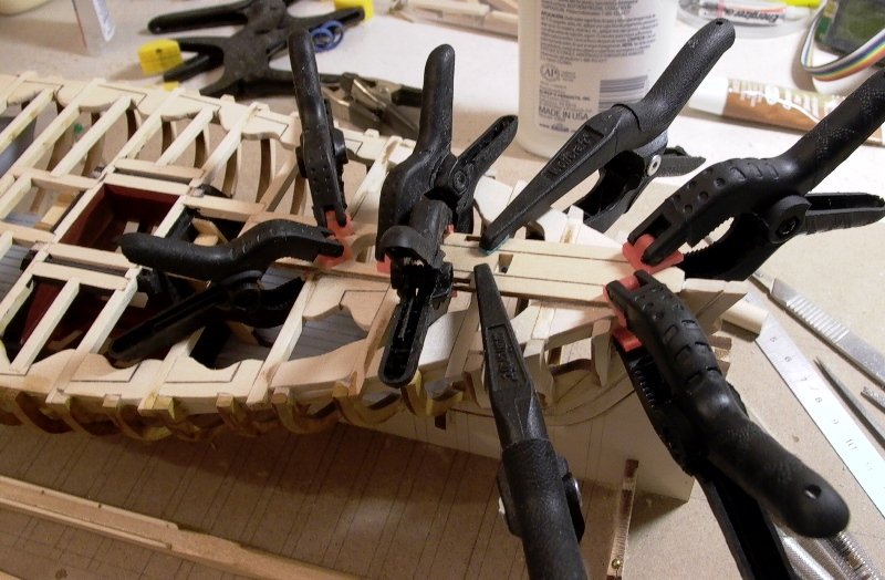
The installation of the clamps change the picture completely, and your hull will become suddenly very stiff and solid.
Cheers.
Yves
-
Ben,
I understand and agree with you. I was just wishing and thinking out loud.....

Yves
-
Hi,
I will take some pics of the other castings and post them, If I remember right they were not
as bad as the figurehead ( absolute crap ), but nowhere near as nice as the resin ones that Chuck did - wish he
would make some more ( pretty please )
 .
.ben
Ben,
I wish that when Chuck is done with enhancing his home, he finds the time to produce a small series of add-on accessories for his kits distributed by Model Shipways. The list of parts that needs to be replaced grows with each kit produced:
- Carronades for the Syren (although, MS did an effrot by providing free replacements for the ugly appendices that came with the kit).
- Figure head for the Syren
- Figure head for Confederacy
- Stern decorations for Confederacy
- Cannons for Confederacy (turned and in brass)
- Plans for Confederacy rigging
- Kit for Confederacy rigging
...etc
A small business of retrofitting parts could actually be created without hurting Model Expo in any ways and would contribute to turn these kits into masterpieces.
Yves
- Jaxboat and CaptMorgan
-
2
-
Ryland,
This is a beautiful Build Log. I love how you present the kit, the parts, the plans and all your step-by-step progress.
Darn, it makes my mouth water just watching you build that gorgeous kit. Once again, I am going to have to invest in Chuck Passaro, Inc.
I'll be following closely. By the time you are done, your Build Log will become the De Facto Practicum.
Yves
-
Here are the stern decorations the were generously provided by Chuck. They are resin cast by Chuck and then painted by me. I could take 50 years and not be able to sculpt anything close to this.
I wonder how the stern decorations provided in the kit compare with the castings from Chuck.... I know the bow figure is a fiasco in the Model Shipways kit.
Yves
-
Cog,
You are correct. I may have to use a Sharpie marker to finish them nicely.
Yves
-
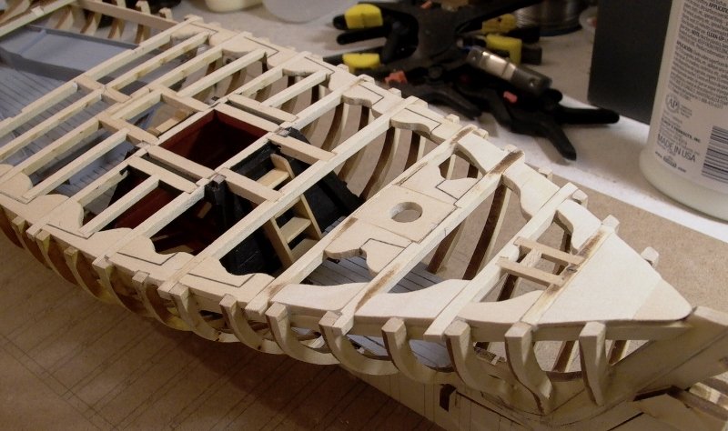
Folks,
As you may remember, we are moving from the bow to the stern (nothing radically unusual there
 ). The central part of the ship is now fully kneeled and beamed (am I inventing new words?). I am still using the section of wood located between two laser-cut main beams, to build the smaller deck beams.
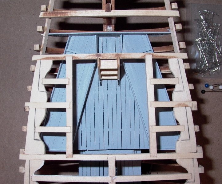
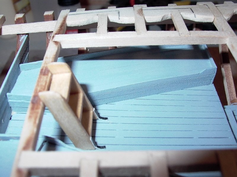
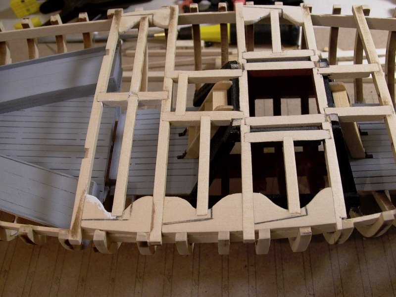
The section above the bunks room is now completed and ready for the deck planking.
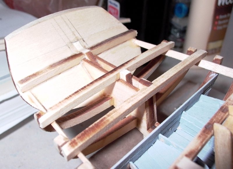
The stern of the craft is a little bit trickier, but not by much. It is necessary to file two pieces of a main beam (laser-cut) and bevel it to create a slant corresponding to the inclination of the stern board.
The beam ahead of the tiller shaft must be filed carefully to embrace the rudder shaft box. It is easier to do than to describe. At this stage, I have 6 knees left to cut (yeah !!!!!) and one more smaller beam and all the beams and carlings will be done.
View into the bunks room:
and view of the stern skeleton:
Finally, an eagle eye view of the whole enchilada:
And now time for a nap......
Thank you for your interest and encouragements.
Yves
- Rik Thistle, Duanelaker, canoe21 and 5 others
-
8
-
Don,
Are you scratch building the Emma C Berry? All the dimensions are on the plans (4 sheets).
The wood provided in the kit to cut the knees is of 1/8" x 3/4" x 24 inches.
Yves
-
Folks,
Since we do not have a repository for the Syren (Model Shipways) any more, I am posting the good news that Model expo started shipping and distributing the new castings of the Carronades for the kit Syren. I just received mine today and here is the new casting based on the original and revisited mold by Chuck Passaro:
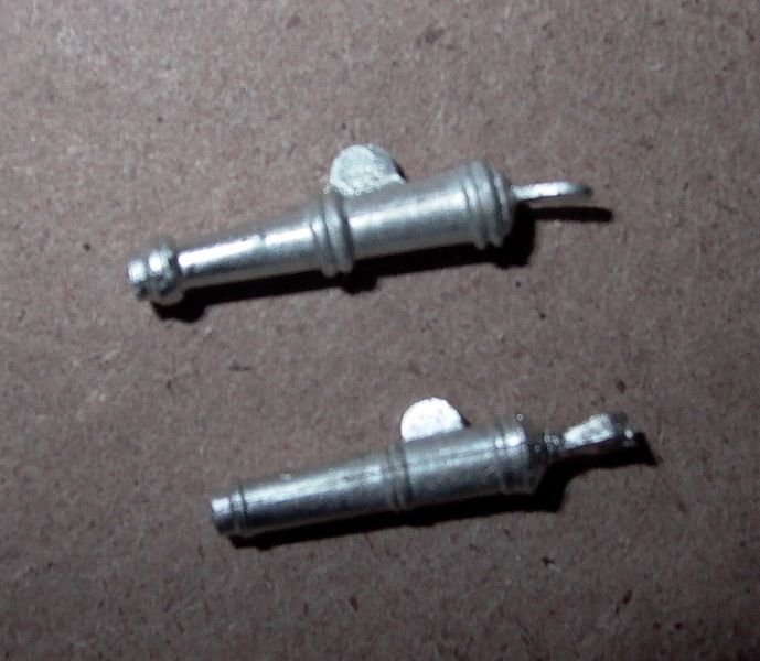
On top is of course, the ugly "appendices" that were shipped with the kit. On the bottom, is the new and much cleaner Chuck Passaro casting.
Yves
-
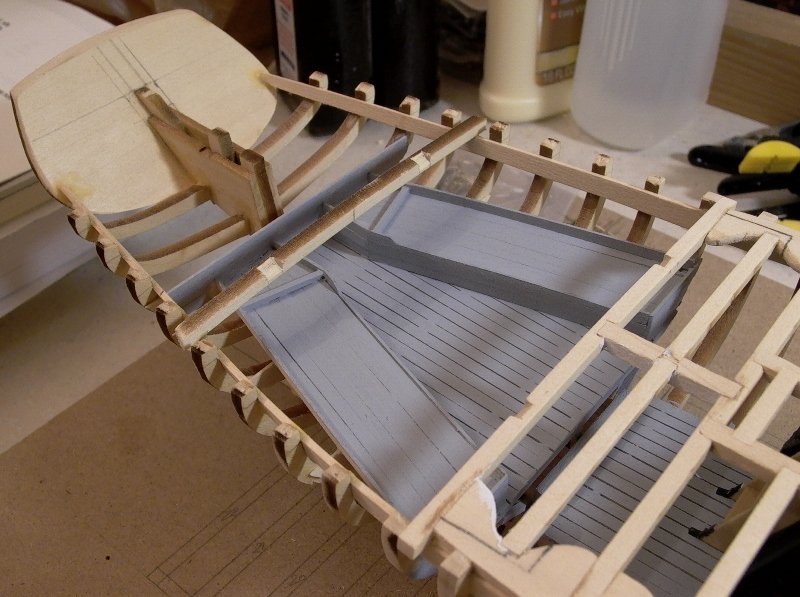
Folks,
Not much progress this past weekend as I was not home. The bow and middle sections of the craft are finished, as far as carlings and deck beams go. I have carved all the knees by hand, using saw, files and sand paper. The whole assembly is sanded smooth, using a block to keep the original shape of the beams, as much as possible. The whole deck has a convex curve from portboard to starboard and a concave curve from bow to stern (like most boats).
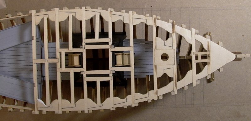
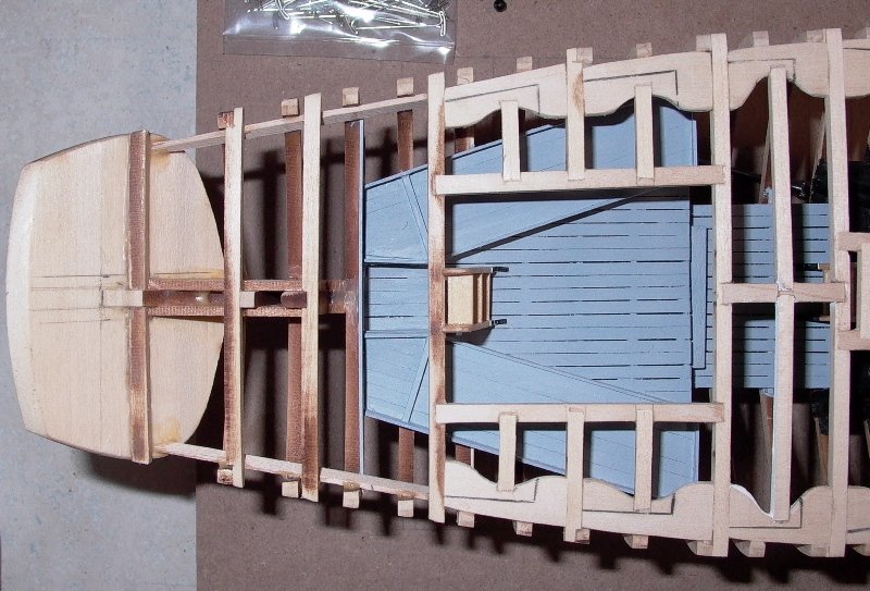
Another view showing the curvature of the deck:
At this stage, before installing the King Plank and starting the planking of the deck, all the inside details must be built and secured with glue as any intervention inside the hull is made almost impossible without the use of long and tiny brussels.
On this model, the starboard side of the deck will be open showing the deck details, knees and the inside of the boat.
We still have the rear deck to build and some details around the bunks. I am thinking about a couple of pillows, mats and some tiny details that may become visible through the various openings. An additional ladder will be necessary to access the bunks room.
Stay tuned.
Yves
- GrandpaPhil, pete48, canoe21 and 1 other
-
4
-
Don,
The wood used for the clamps is basswood of 1/16" x 1/4" and about 20 inches long. They are glued to the frames with yellow carpenter's glue.
For the deck beams, as indicated I used all the main beams (provided in the kit) and the smaller pieces of wood left in between on the laser-cut sheet. The smaller pieces are slightly less deep, which is perfect and very realistic, giving the illusion that the main beams are bigger. With this way of doing it, the deck has a regular and monotonous shape.
For the knees, I paid special attention to the knees that will be visible (I intend to have a part of the deck under repair) and used the plan rather liberally. For ultimate pickiness, you could trace the knees on the wood using carbon paper or tracing paper and cut them with a scroll saw.
Thank you for your encouragements.
Yves
-
A few progress over the weekend. I have decided to concentrate on the
bow of the ship and finish as well as possible all these "pain-in-the-@$$" knees.I do not have a scroll saw and each knee is cut by hand and
filed by hand. It is very time consuming and not much progress is done.Below is a picture of the center of the craft, showing the intricate deck beams and carlings:
Moving to the bow, I have almost completed the knees. I am just
missing a small triangular piece that will go under the Kingplank and
make this one very stable and solid. The original knee is open with a
small oval cut, which I skipped.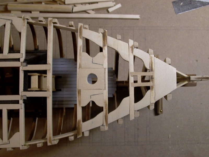
The center knee responsible for holding the mast requires some careful
planning and filing as it will drive the orientation and inclination of
the mast. Careful measurements must be taken. In my case, the mast is
perfectly perpendicular (Starboard/Portboard) and only a tiny shim may
be required for the rear/forward leaning and to lock the mast in place,
on the keelson: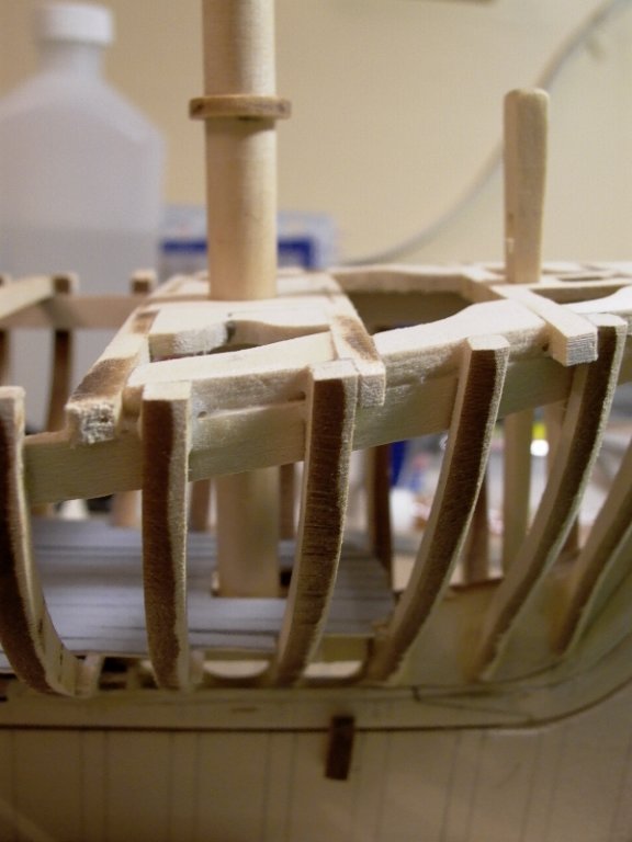
Because there is also the need to build the mortise for the bowsprit,
I decided to change pace and instead of fabricating more knees by hand
(no pun intended...), I jumped to the building of the spars.I remember reading the Syren Build Log by Chuck Passaro, who admitted
that his favorite part in a ship project, was to build the masts and
spars. I have to agree with him on this one and found the polishing and
shaping of the bowsprit a very relaxing and involving activity. The
shape is constantly evolving, as it moves from 4 sides to 8 sides,
coming back to 4 sides again, to 16 sides with a flat top allowing the
crew to walk and store the genoas and gibs.....to finish simply round.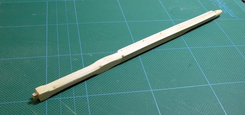
Here again, I am using Chuck's little secrets to turn a piece of
basswood into something resembling a precious wood, polished and smooth
like pear or boxwood. After finely sanding the bowsprit, I rubbed it
using a piece of white cotton with some Wipe-on-Poly. This chemical
prepares the wood and covers it with some kind of acrylic barrier that
seals the pores and stains my cheap basswood with a beautiful light
golden hue. The picture does not make justice to the actual quality of
the part finished. At the end, it will be painted with acrylic white and
black colors, but in full honesty, it could stay like this and be
simply marvelous.To finish our presentation tonight, a picture of the bow with its mast and bowsprit installed:
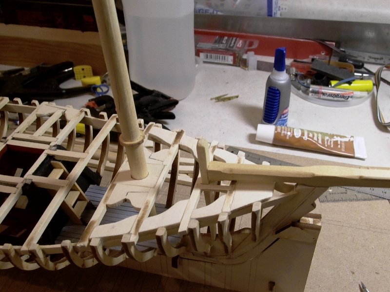
Stay tuned.
Yves
- canoe21, GrandpaPhil, Duanelaker and 3 others
-
6
-
Folks,
I have made little progress recently and I am working on installing some
of the main deck beams, concentrating on the bow and front of the ship.
I still have to build a third ladder for the access to the bunks cabin (from the rear house).
I have debated about installing the ceilings in the inside of the boat and decided otherwise. The three main reasons are:
1) I am too advanced with the installation of the deck beams, which is making the planking of the ceiling a nightmare.
2) There is very little data to how the ceiling was installed in this
craft, and the renovated Emma in mystic does not have any, to my
knowledge.
3) I want to be able to see through the hull and the ceiling would prevent a view of the well and the bunk cabin.
4) I am lazy ....
Hopefully, I will post more pictures soon.
Yves -
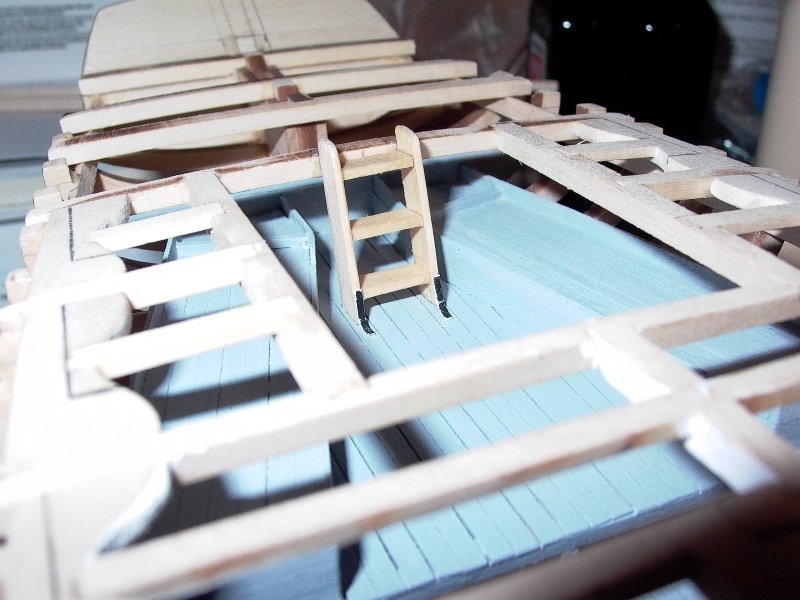
A few little progress: access ladders and a couple more knees.
The ladders are built using the leftovers of the main clamps. They are
respectively 4.3 mm long and 4.5 mm long. Width is 1/2 inch or 12.7 mm
for the rungs. I decided to install 4 rungs/steps on each.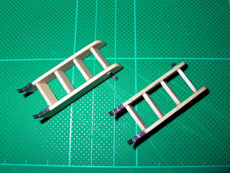
The basswood of the ladders is first wiped with Wipe-on-Poly to remove some
of the grain and prepare the wood to staining. I am using these tricks
from Chuck Passaro described on his multiple threads about building
Syren and Confederate. The wood is then stained with Sherry Min-Wax. It
is very light in color and will stand out better in the dark confines of
the inside.
Small paper strips are cut and glued to simulate the
metal parts used to secure the ladders to the floor and frame of the
ship. Tiny drops of AC glue are supposed to represent bolts or rivets.
Mine are not too realistic and I should use liquid AC next time instead
of the Gel glue. It may create a rounder and fuller bubble.
The ladders are installed in the hull, leaning against the well. The front Ladder: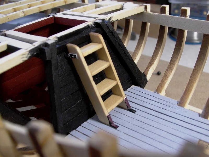
and the rear ladder: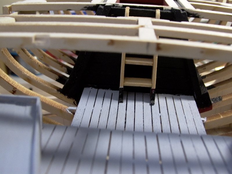
Finally, I made two more knees and used again the in-between parts of the main
deck beams (from the laser cur sheet) to build the intermediate beams: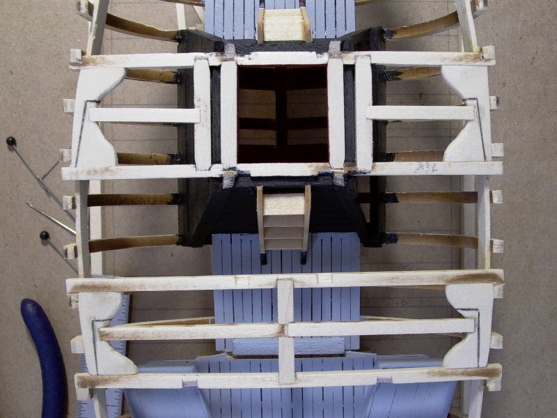
With the ladder installed and pretty much the interior of the ship finished,
I can move ahead and finish building the deck beams. Once this is done,
access to the inside of the hull, will be almost impossible with my big
fingers....
Yves- Duanelaker, Dubz, GrandpaPhil and 2 others
-
5
-
Folks,
Here is the picture I found on the Internet, showing the
inside of the Emma C Berry during restoration. As you can see, some of
the frames have been doubled and painted white, as part of the
restoration process.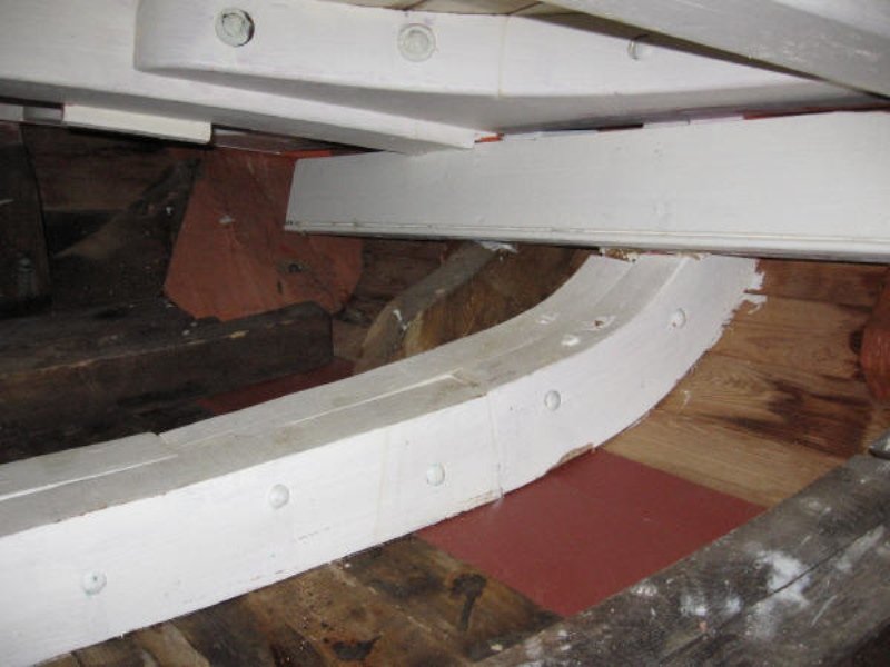
Clamps, knees and deck beams have also been protected by a coat of white paint.
Only the original frames seem to have kept their patina.
I may do that on my model: use an aging wood stain for the frames and paint
all knees and deck beams with white acrylic. It should look good and
allow a lot of inside details to stand out.
Yves- GrandpaPhil, pete48 and canoe21
-
3
-
Guys,
Thanks for your compliments and encouragements.
I do not have too much time, just a few minutes every day to dedicate to
this build, so it will go slow at times. Right now, I am working on the
knees and deck beams. I am planning to show a portion of the deck
un-planked and thus must build the knees and a maximum of details
underneath. However, where the deck will be covered, I may not do the
knees, or replace them by a piece of wood of the proper thickness.
For the time being, I have done two of them, in the center of the deck
where they will be visible from the top or from underneath, through the
opened hull.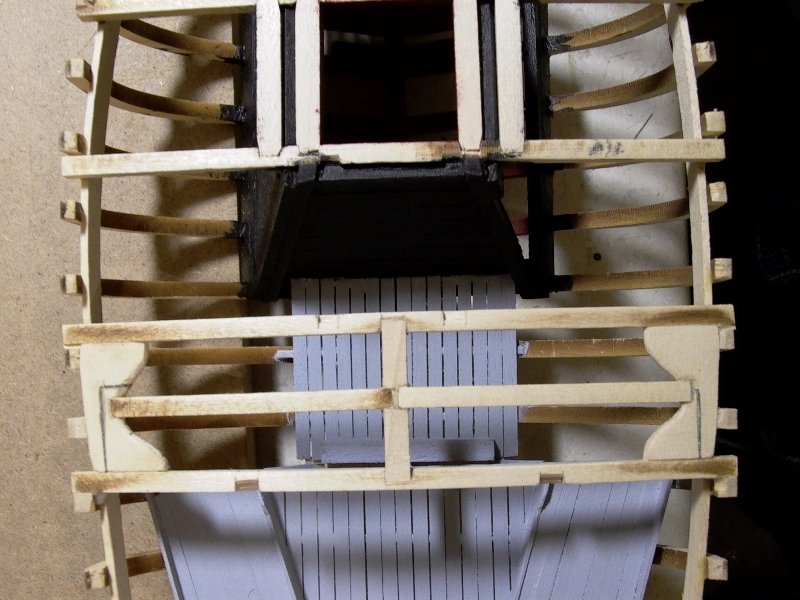
Model Shipways provides in the kit a small laser cut sheet with only deck
beams. Unfortunately, and this issue has been raised by other modellers,
the curve and shape of these deck beams are not matching the main
beams, causing an uneven deck. I solved the problem by simply not using
the small laser cut sheet, and relying entirely on the main deck beams
and the pieces of wood, in between them. The fact is that these
separations are of the exact same curvature, and are slightly less thick
than the main beams, making it a perfect fit.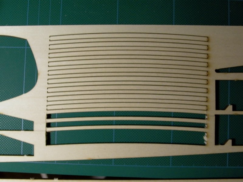
The result as you can see is very good and the curve of the deck is
constant and even. To install the pseudo deck beam, just cut them off of
the main laser cut sheet, place them equally/centered across the hull,
as if they were a main beam, and mark your measurements before cutting
the pieces.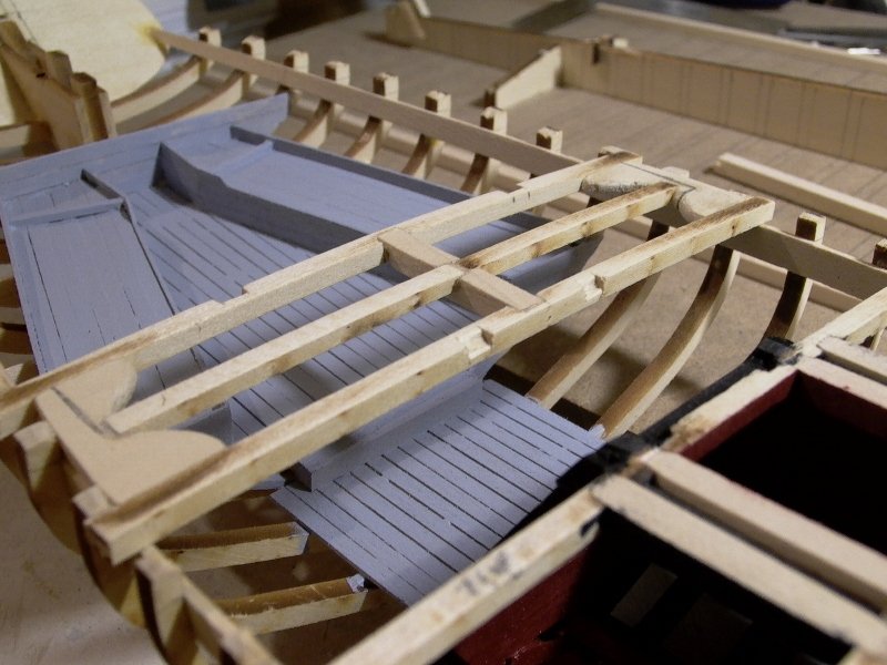
Now, we just have a few more knees to build and a lot of beams to cut and sand gently.
In the restored Emma C Berry at Mystic Seaport, the knees and deck beams
are painted in white color. Although it is not possible to board Emma
and go below, I came across some pictures on the Internet showing the
inside of the hull during the restoration. All the new double frames,
knees and deck beams are painted in white. I may do that on my model.
We'll see.
Yves- GrandpaPhil, canoe21, Duanelaker and 3 others
-
6
-
Thanks to Firefox Caches, I was able to recover the beginning of the Build Log. Here it is for your pleasure:
Folks,
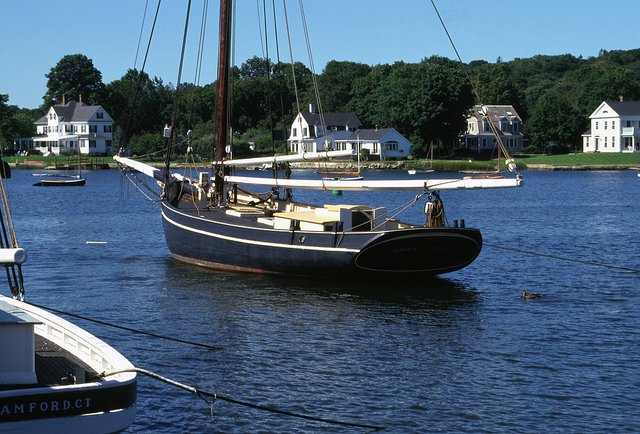
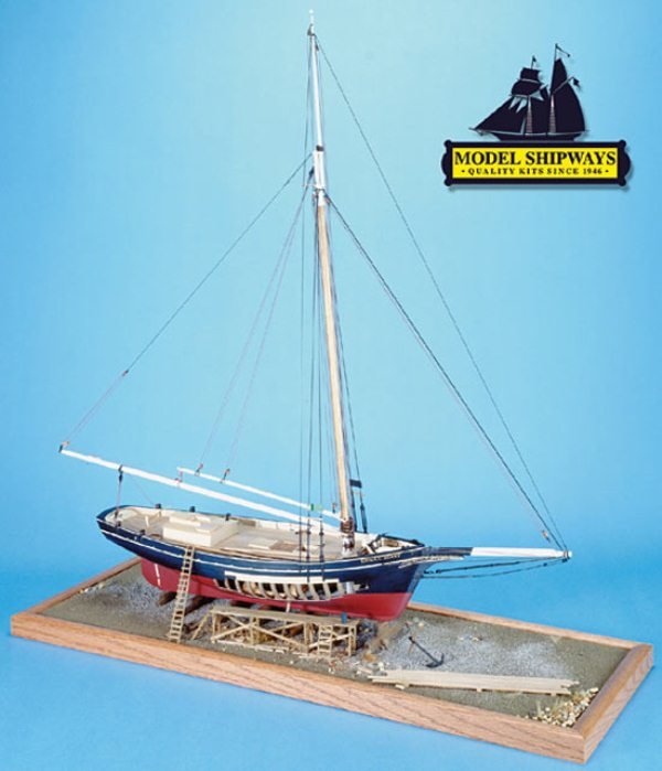
Here is another log of that famous little boat, made by
Model Shipways at the scale of 1/32. It is a serious kit for moderate
level as it is a planking on frames. The instructions are also rather
fuzzy, allowing you to approach the building in your own way. The
booklet going with the kit is starting to show its age and the
instructions provided are in no ways comparable to modern assembly books
provided by Amati or the ultimate perfection such as the instructions
booklet written by Chuck Passaro. At times, this kit feels like you are
actually scratch building this beautiful model. The use and selection
of wood strips is sometimes rather blurry and you have to use your best
judgement. Along the assembly phases, you will have to be careful about
saving the wood and strips, as there is none or very little spare. The
picture below was taken by a member of this forum and graciously posted
for all of us to enjoy. It is a beautiful picture showing the elegant
and timeless lines of that little fishing boat resting at Mystic
Seaport, in Connecticut:
Fortunately,
the Internet abounds with information about the Emma C Berry and this
forum has a couple of Logs which have helped me tremendously. I wanted
to express my sincere gratitude for the wonderful Build Logs by Maurys
and Anno1766 (Ovali) as well as a Russian Modeller whom I ignore the
name.
A lot has been said about Emma C Berry from Model Shipways,
and thus I will simply present some pictures of my own model and
elaborate on a few delicate steps (delicate for me, of course) of the
construction.
The first picture shows the kit offered by Model
Shipways. This is exactly as I intend to build the model, with a view to
the inside of the hull, the inside of the well and some of the deck
planking removed.
I got my kit from EBay at a very good price as Model Expo runs some
specials occasionally. The kit cost me less than $100.00, which is a
real bargain. There are also some people who are selling kits that they
bought long time ago and never got to put together. It is a common
practice among modellers to accumulate kits and realize a few years
later than the spark to make them is gone. And so is the time and
energy.
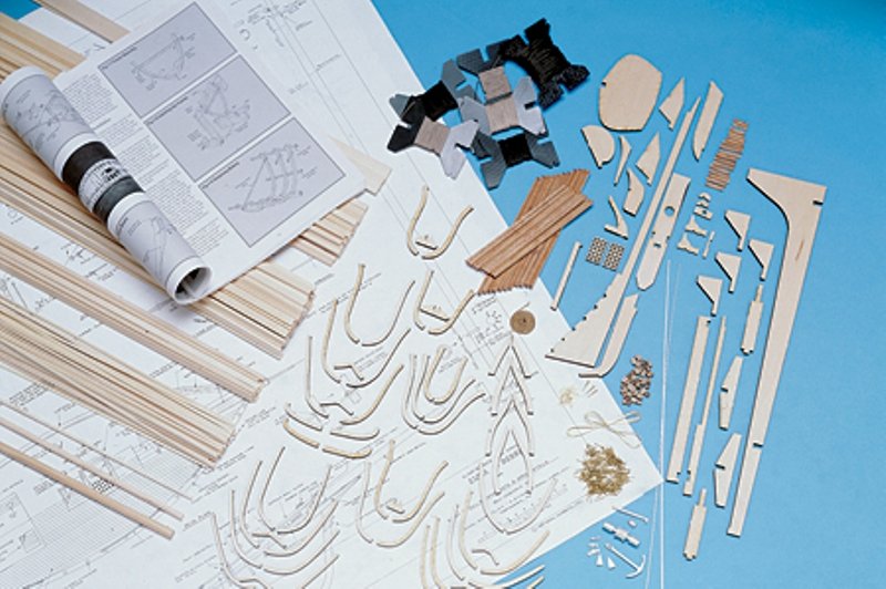
The picture above from the Model Expo site, shows some of the parts in the kit.
The
kit provides an excellent way of building the complicated hull of Emma.
We have no less than 25 frames to be glued to the keel. A stand sliding
parallel to the keel allows you to position each frame perfectly. The
important thing here is to position the top of each frame according to
the distance measured on the plan. Also, make sure that the frames are
centered. Everything else is not too difficult.
I approached the
gluing of each frame in the following way: Glue both sides of the frames
on the plan, using CA glue. Prior to gluing, frames which need some
beveling are lightly sanded but not much. It is in fact much easier to
fair the hull later, when all frames have been glued and stiffened by
the clamps. In addition, the fairing will be true and smoother than if
you were to bevel each frame individually. You can trust me on that one:
once the clamps and the deck beams have been installed, your delicate
assembly of frames will not budge under the frictions of the sand paper
block.
With this approach, I managed to glue one frame per day,
and sometimes two per day. Frames were glued to the keel using Yellow
Carpenter Glue which is very hard once dried.
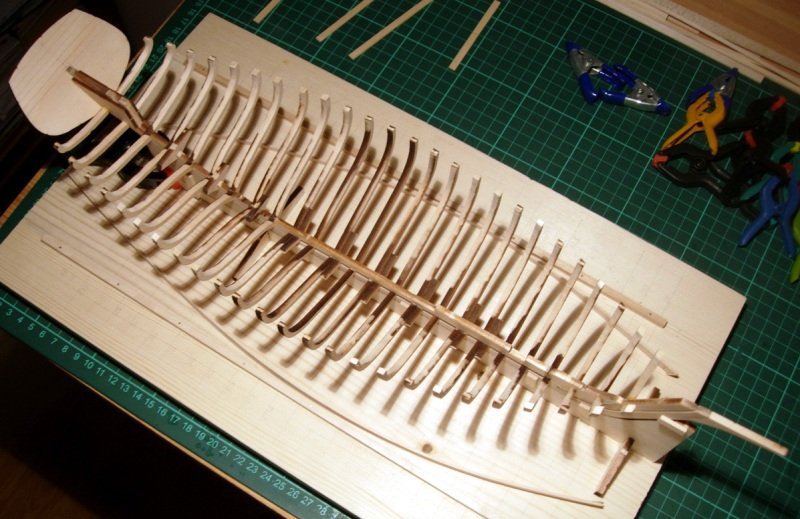
The following
picture borrowed from the Russian modeler (I did not take any picture of
my build at this early stage) shows the entire set of frames installed
on the keel. The view is glorious and that boat resembles the bone
system of a fish. It is quite a sight. It also makes perfect sense why
early ship architects would have used such approach to build boats: just
observe nature and replicate it!
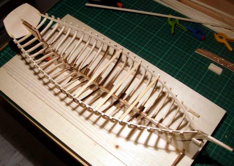
At
this stage, the structure is very, very fragile. The wood on my kit is
brittle (probably old - kit was dated 2003) and you have to be careful
when handling it. Fortunately, the installation of the clamps is going
to change completely the stiffness of the hull. Again, on that previous
picture borrowed from our talented Russian modeller, you can see the two
clamps which were pre-bent, after soaking them for 10 minutes in hot
water. The picture below shows the clamps installed. I glued mine with
Yellow Carpenter's Glue again, for extra strength. A cloth pin was
installed on each frame and left drying for an entire night (50 pins
total).
Thanks
to the clamps, the hull is suddenly very stiff and flexible at the same
time. You can twist it gently, and it snaps back in place, perfectly
straight and sound. Those clamps are playing a critical role in the
stiffness of the hull. At this point (and I would wait to have some deck
beams installed), you could almost start fairing the hull in
preparation for the planking. However, before we plank, there is all the
inside and deck to be built.
Since very little is known about
how Emma C Berry was equipped when it was active, there is a degree of
freedom which is allowed. The well is precisely described on the plan,
and I decided to build mine partially open as I want to show the boat
under restoration (as depicted on the cover of the kit box). Besides,
that well is a unique feature on a sailboat and deserves some attention
and questions from the people who will look at the model.
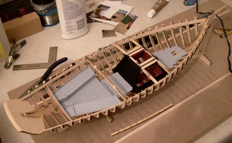
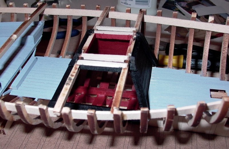
The
well is painted inside, with acrylic red approaching the anti-fouling
paint used to repel clams and algae. The outside of the well is painted
with Payne's Grey, also in acrylic medium:
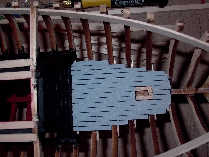
The
front of the boat is simply equipped with a flooring made of small
basswood strips and painted light grey with a hue of blue, of my own
mixing:
The
rear section of the hull is equipped with two bunks as suggested by the
restoration book from Mystic Seaport and the plan of the kit. Again,
the same acrylic color is used. Most of the structures are made with the
tiniest strips provided by Model Shipways and glued first with CA glue,
and later on re-enforced with white glue for additional strength.
http://imageshack.us/a/img96/6199/emma5y.jpg
With
a couple of deck beams glued in position, the hull is now very stiff
and the fairing can be done with a block of sandpaper equipped with 100
to 180 grit.
Yves- Vladimir_Wairoa, pete48, canoe21 and 3 others
-
6
Emma C Berry by yvesvidal - Model Shipways - 1/32
in - Kit build logs for subjects built from 1851 - 1900
Posted
Final pictures for a little while, of this project. Details of the bow and the bowsprit holder:
and an overall view:
Hasta la vista.
Yves