HOLIDAY DONATION DRIVE - SUPPORT MSW - DO YOUR PART TO KEEP THIS GREAT FORUM GOING!
×


SJSoane
-
Posts
1,649 -
Joined
-
Last visited
Content Type
Profiles
Forums
Gallery
Events
Everything posted by SJSoane
-
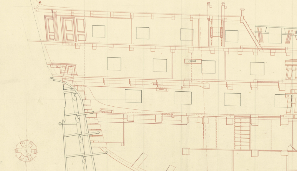
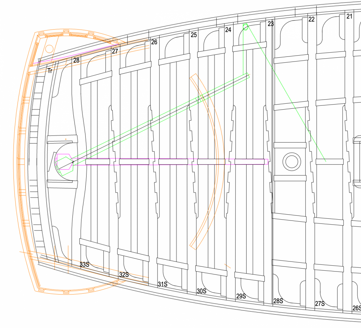
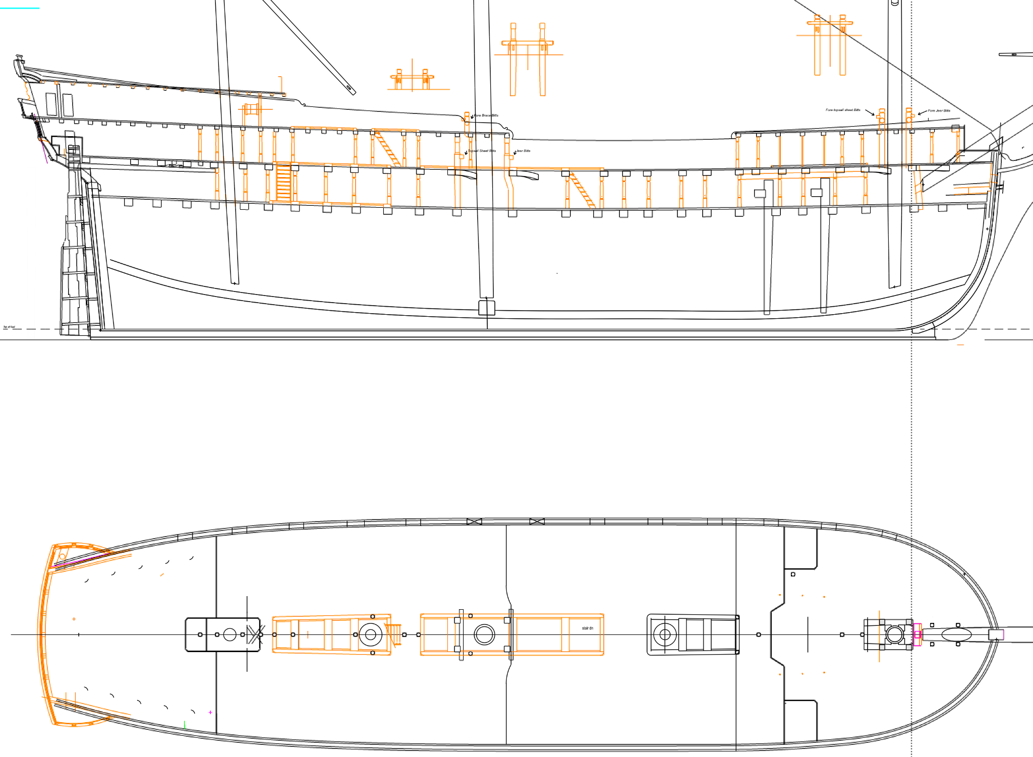
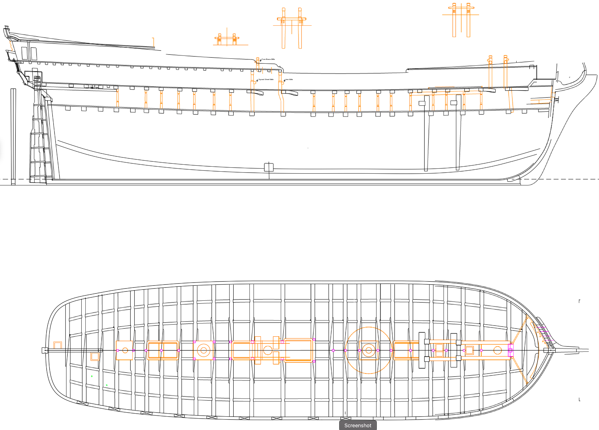
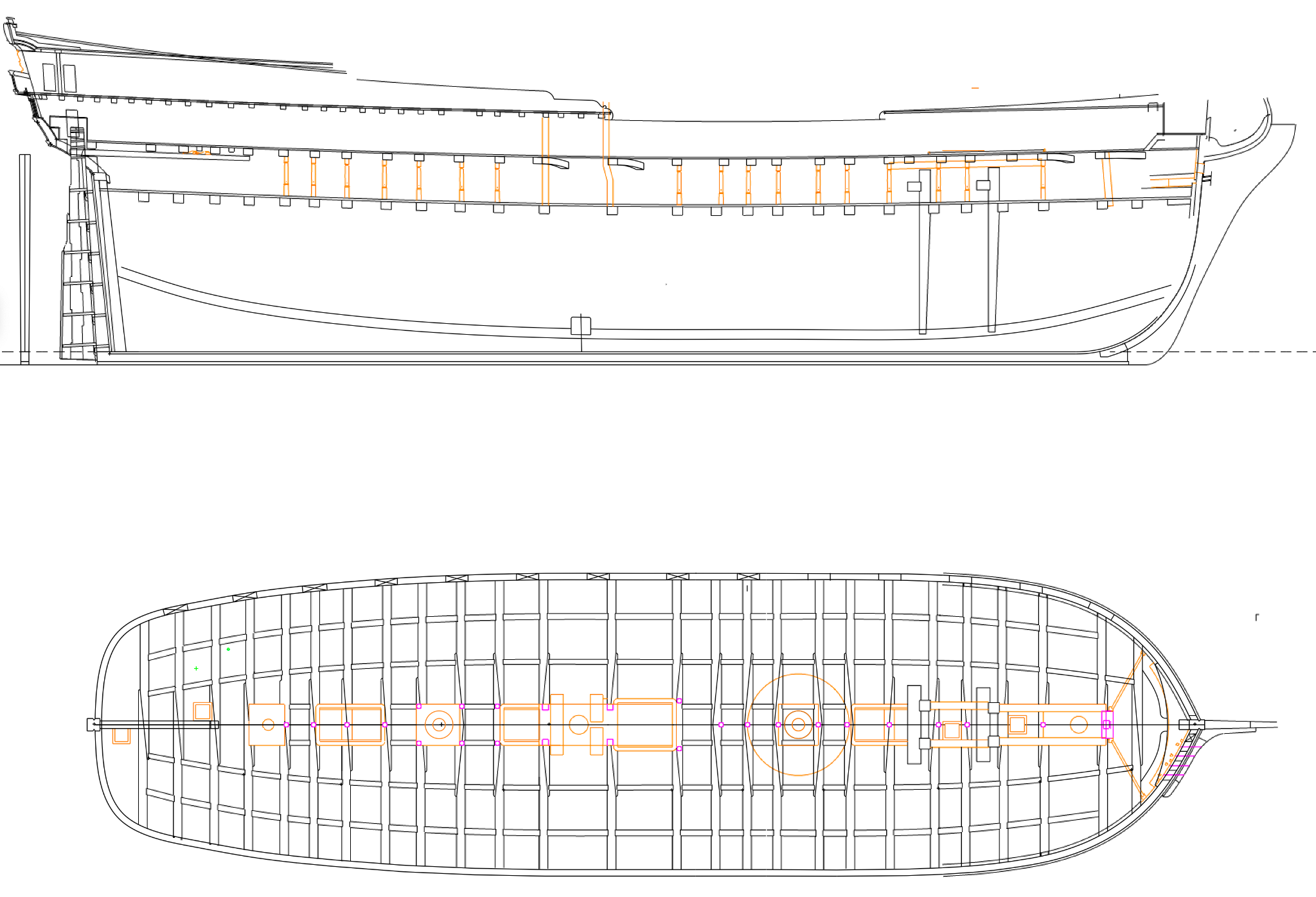
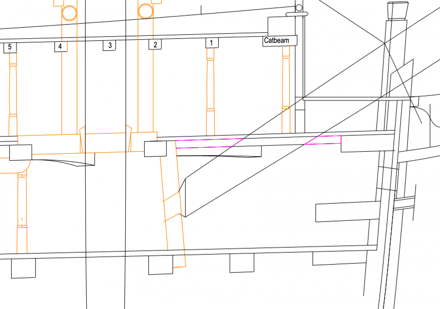
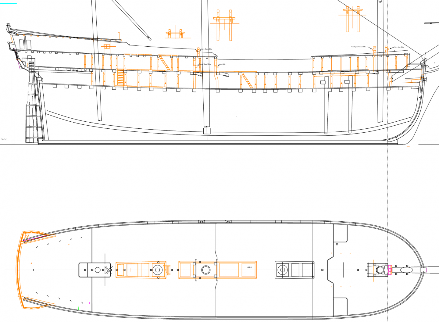
 Hi Gary, Many apologies if I am late to the party in helping think about this bowsprit deck framing question. Too many things taking me away from the shop lately... But here are some more thoughts. I have always wondered about those delicate little diagonal pieces in the forecastle partners for the foremast in the first Bellona model. They can't make sense as real partners, so they must be a model-making shorthand for saying "partners go here". Although why they would detail everything else accurately and not this, I have no idea... So if that is the case, then I think druxey is right in saying that the real issue is how to land the planks around the bowsprit, coming in at an angle to the deck. I agree with Alan that this does not have to be structural, because there is already the step, the top of the stem, gammoning and stays holding the bowsprit in place. I drew in purple the areas where a "thicker than planking" but "thinner than a structural step" would be needed to land the planks around the bowsprit. There would not be a need for planking fore of the bowsprit as Siggi pointed out, particularly since it is directly beneath the platform at the beakhead; but aft is definitely a walkable area needing planking. So is this like the thicker baulking around the opening for the rudder at the stern of this deck? the purple highlighted in the cross section is the depth of the carling on either side of the bowsprit. Maybe the baulking could be a little thinner? Best wishes, Mark
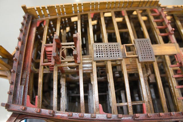
-
Exceptionally eautiful work, Karl, as usual for you! I like the way you make a pattern for the hanging knees, using little pieces with a general template. I will use that idea! Mark
-
Hi Gary, I just caught up on your postings. It sure is helpful to see you working on all of the things that I know are are coming next for me! I will look around a little to see if I find anything about where the bowsprit goes through the deck.... It is looking great, including the beakhead bulkhead framing! Mark
-
Hi Alan, Great news! Now you will always have that feeling when you look at one of your details blown up in high resolution photos! Yes, I was also struck by the contrast between the precise rules for sizing blocks relative to rope diameters, only to see in Steel's tables that there is not a close correlation in many cases. They did seem to standardize on some basic block sizes, so as not to have to carry hundreds of different sized replacements. So why did they not say, "for circumferences from x to y, the sheave size is z". Who can I call about this.....😏 Mark
-
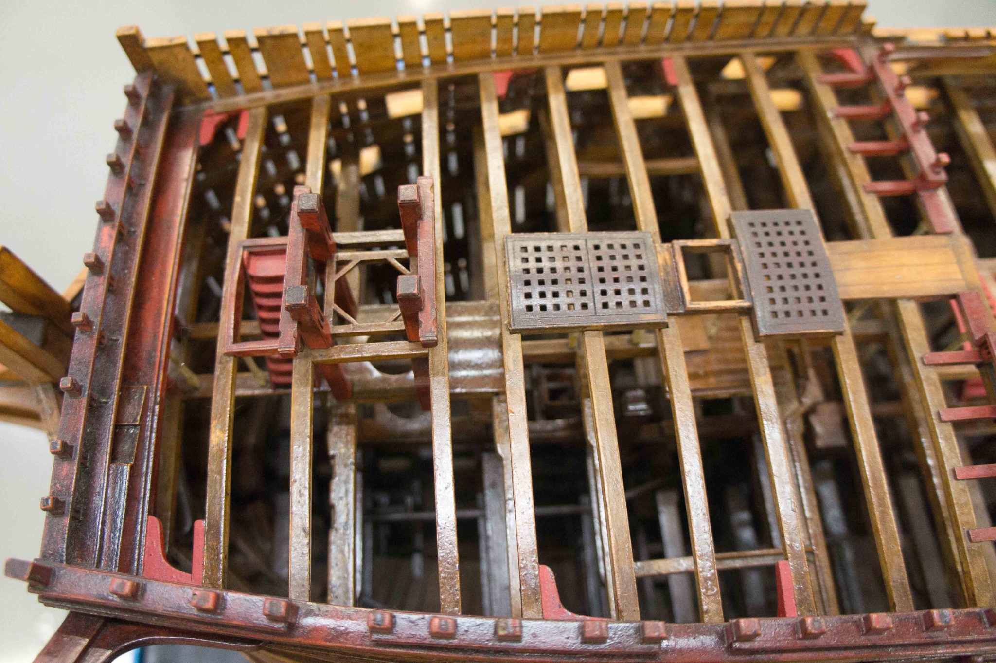
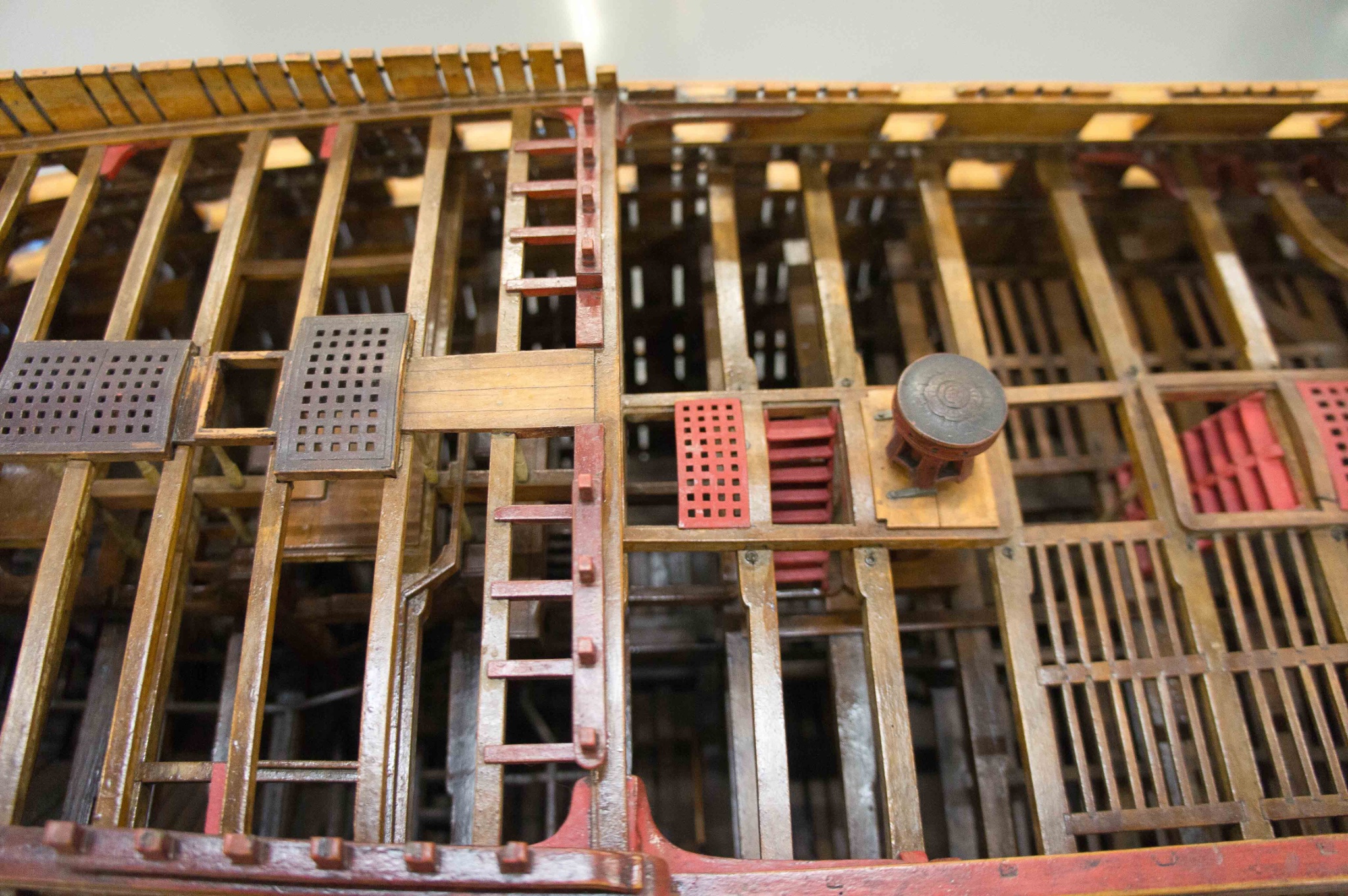
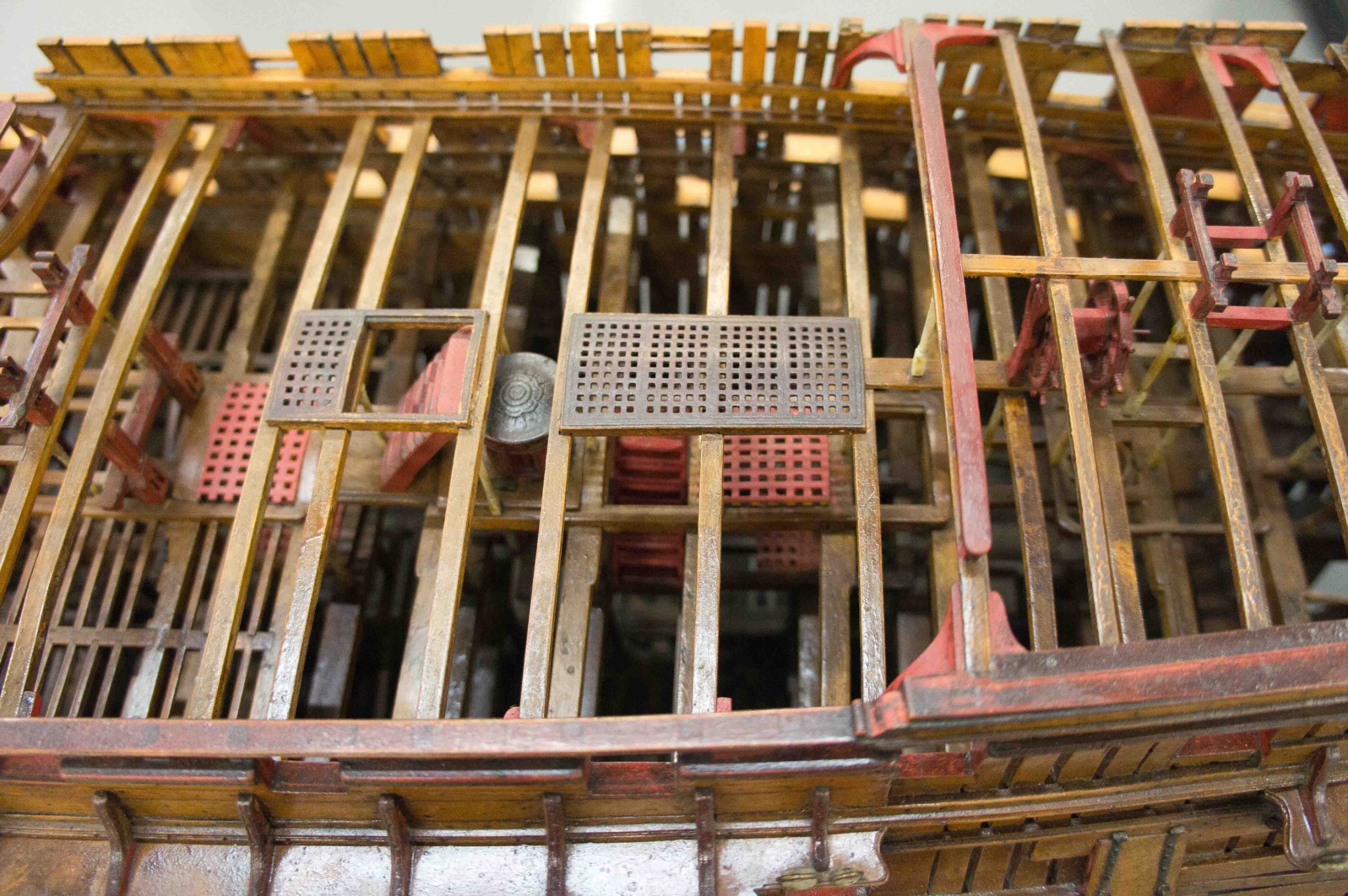
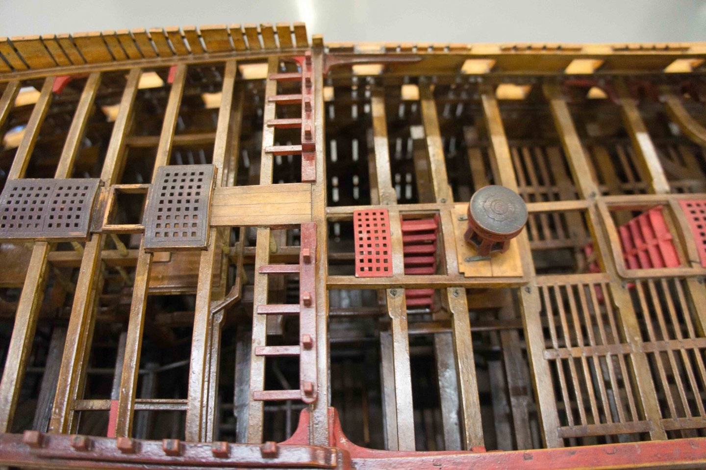
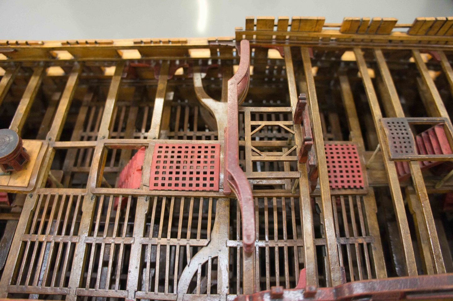
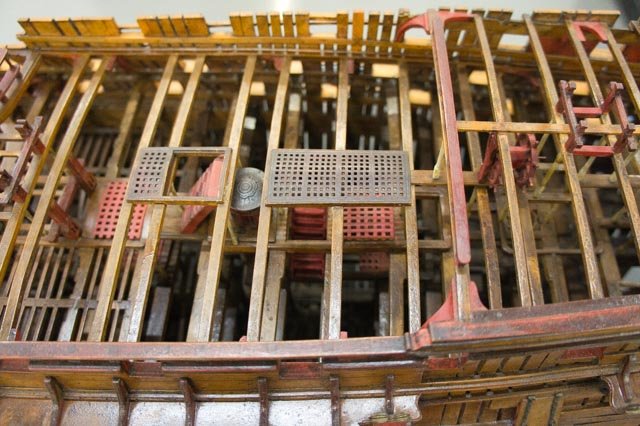
Hi druxey, I see now. I confused its length because of the wheel handle coming down in front. So it looks like it would be shorter than the actual travel of the rope lock to lock, but more than chafing in a hole just a little bigger than the rope. I will use it, because I would reasonably guess the sliding cover as in Victory would have been something later than 1760. More work on the pillars, now on the upper deck reaching to the quarterdeck and forecastle. I am mainly working from what I can see in my photos of the original Bellona model (below), and what seems rational. For example, no pillars beside the aft hatch, and therefore no pillars possible there because the centers do no line up with any beams above. No pillars close to the bitts, because they are providing vertical support at their locations. Except, the model shows pillars under the fore brace bitts on the quarterdeck. Also, iron columns beside the stove. I am not sure about pillars in the wardroom on the upper deck. It looks like there are more in the last photo below, but I can't quite see if it is every beam, and how far astern. I seem to have more beams in the quarterdeck over the wardroom than the model shows, but my beams are taken directly from the original dockyard drawings. 5:00 Mountain time, sun over the yardarm, and time for a scotch to think about it! Mark


-
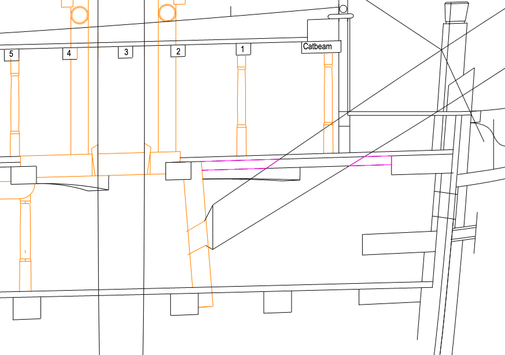
I have been pulled out of the workshop by other stuff for a while--don't you hate how that happens?--but back to it! Thanks, Gary, I added those additional pillars: It is a little tight on the tiller, I may have to trim it back just a bit. And the one just forward of the fore riding bitt has to miss the square hatch on the gundeck, so it stands just aft of the beam in the upper deck above. Maybe it just ran up to the deck above, or maybe it was longer and bolted to the side of the beam above. I am showing the carlings under the stove in the section above, but they are on the sides, not the center, so they don't interact with the central pillar. Or maybe the pillar at this point is two, so it can sit under the stove carlings at this one location? druxey, thanks for that photo. If it is indeed a single hole with a hood, then I guess they didn't originally worry too much about chafing. Because the initial sketch you sent, and that I redrew for the Bellona, clearly shows the rope will traverse back and forth from the wheel. Interesting! My photo of the original Bellona model frustratingly shows no detail here. This issue shows how a technological invention--the steering wheel--had to be adjusted over time as experience showed some of the shortcomings of the original version. Happens at light speed today, much slower back then. We might have enjoyed a slightly slower pace of life! Mark


-
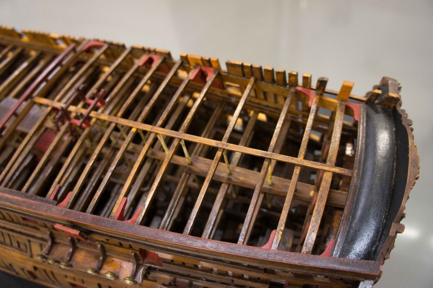
Wow, those are beautiful, Gary. I see why you chose this one. And I see it has a smooth, serpentine curve on the stern balcony, just like the original Bellona. The later Bellona brought the balcony in to a sharp corner at the frame ends, which I don't think is as graceful as the one you and I will be building. Mark
-
Gary, Thanks so much, I completely forgot about that image of the Ajax. I used that to map against the Bellona gundeck framing, and with the exception of a beam or two not the same, they pretty much line up. The pattern seems to be this: no pillars aft of the mizzen mast, because they would interfere with the tiller. A single row in most places, except around the aft capstan and the hatches around the mainmast. They match up to every beam in the upper deck, needing a little offset on the gundeck in order to center on the upper deck beams. The only beam that cannot get a pillar is the one directly forward of the riding bits. The gundeck and the upper deck beams are too offset to match. thanks so much, Gary, you really helped me figure this one out! Best wishes, Mark

-
Hi Gary, I see you changed the name of your build to HMS Montague/Alfred Class. I am curious, since I don't know the history of this class. Was the Montague before or after the Alfred, and were there major differences in decoration, etc.? Best wishes, Mark
-
When in doubt, look at the original source! I wish my brain worked better in retirement.... Here are my own photos of the Bellona first model. The pillars clearly run down the center, except where the center is interrupted by capstans, bowsprits, etc. And heads are always aligned with a beam, whereas feet can land on the binding strake when the beams do not line up. I guess I will just start plotting logical locations based on this observation, and see how things turn out! So now we know, a 74 primarily uses a single row, a first and second rate use two rows. Best wishes, Mark

-
I finished cutting the upper deck beams this morning, looked at the website, and discovered a rich conversation going on here. Thanks, everyone, for participating in these endlessly fascinating issues in the design and decoration of mid century 74s. Gary, the section of HMS Glory gives great detail on the pillars and much else. Thanks, I had not seen this before. I also looked at John McKay's Anatomy of the Ship for the HMS Victory, and his drawings seem to agree with the Glory section regarding the pillars. In section (p38-39), between the gundeck and the middle deck, there is a pillar for every beam in the upper deck framing, stopping just aft of the mizen mast, and just forward of the foremast. This is to avoid the manger and the tiller. Most of the time, the beams of the two decks do align, and so the pillars go from beam to beam. Sometimes, they are offset a bit, and the head of the pillar still aligns with the middle deck beam, but the foot sometimes lands on the binding strake, not the beam itself in the gundeck framing. And there even appear to be some crooked pillars, like a lazy Z, that connect two offset beams to each other. The locations are more spotty between the upper deck and the quarterdeck/forecastle, I need to study more the rationale for this. The Victory clearly has two rows of pillars. It's beam is 50'-6", while the Bellona is 46'-9". Could 3'-9" less span in the Bellona mean it could have gone to one row down the middle? Still so much to figure out! Mark
-
While taking a break from the monotony of cutting beams, I started to look at the relationship between the beams of the gundeck and the beams of the upper deck, where certain things have to align, like the main bits, bowsprit step, etc. This then caused me to think about the pillars for the first time. I don't have a clear idea of where they are positioned. Brian Lavery's book on the Bellona shows them down the centerline of the hull in a cross section on page 42, and in a perspective cross section on page 43 he shows two athwartships next to the capstan; but he doesn't show any of these in plan. The contemporary model of the Princess Royal in Rob Napier's book has two rows of pillars on the middle deck, running down either side of the hatches, etc. But there are none in the fore or aft ends of the deck. And none I can see between the upper deck and the quarterdeck and forecastle. There could be two rows as opposed the one Lavery primarily shows for the Bellona, because the Princess Royal is a larger ship. Also, these are supposed to bear on the deck beams, but not every beam on my upper deck aligns with a beam on the gundeck. So are pillars omitted in these places? Do the pillars sometimes go down the center where there are no obstructions, and then shift to two athwartships where there are obstructions? Has anyone seen more evidence of where the pillars are located on a 74? Just asking for a friend....😏 Mark
-
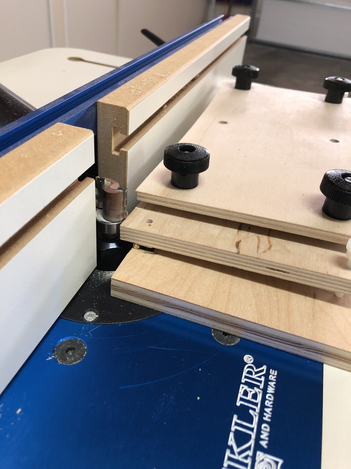
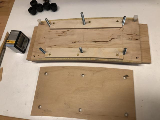
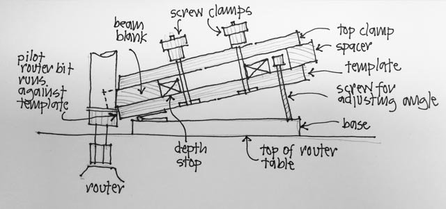
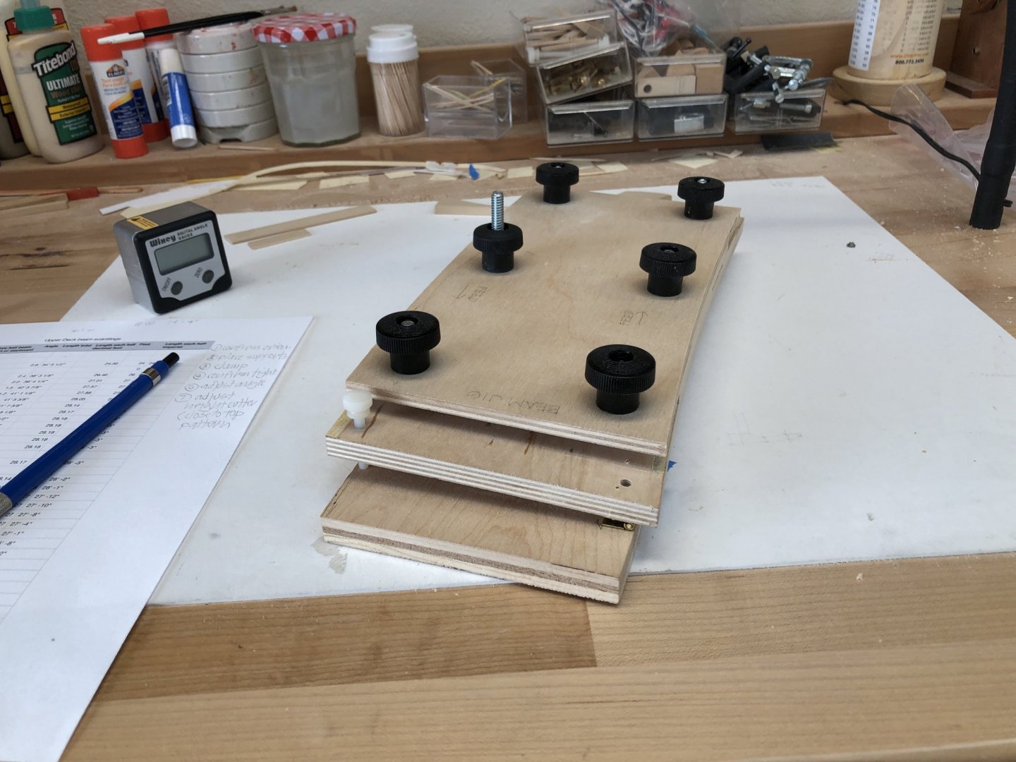
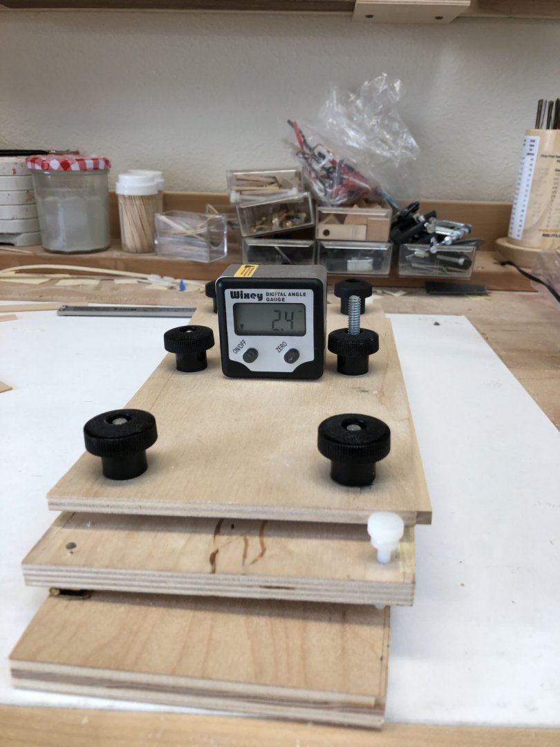
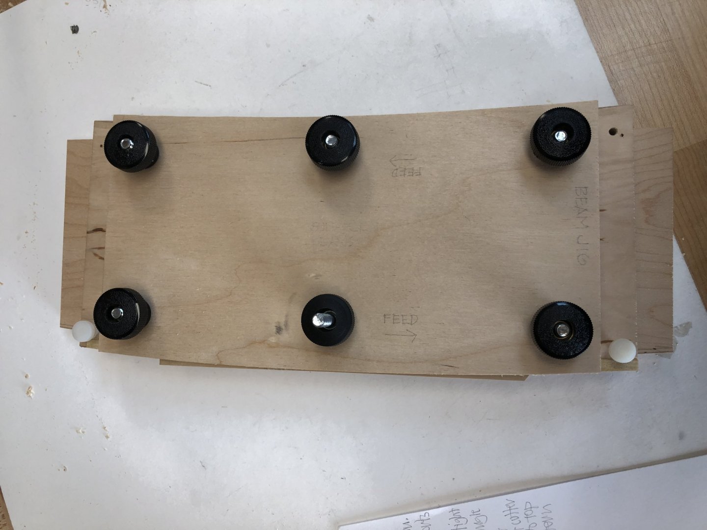
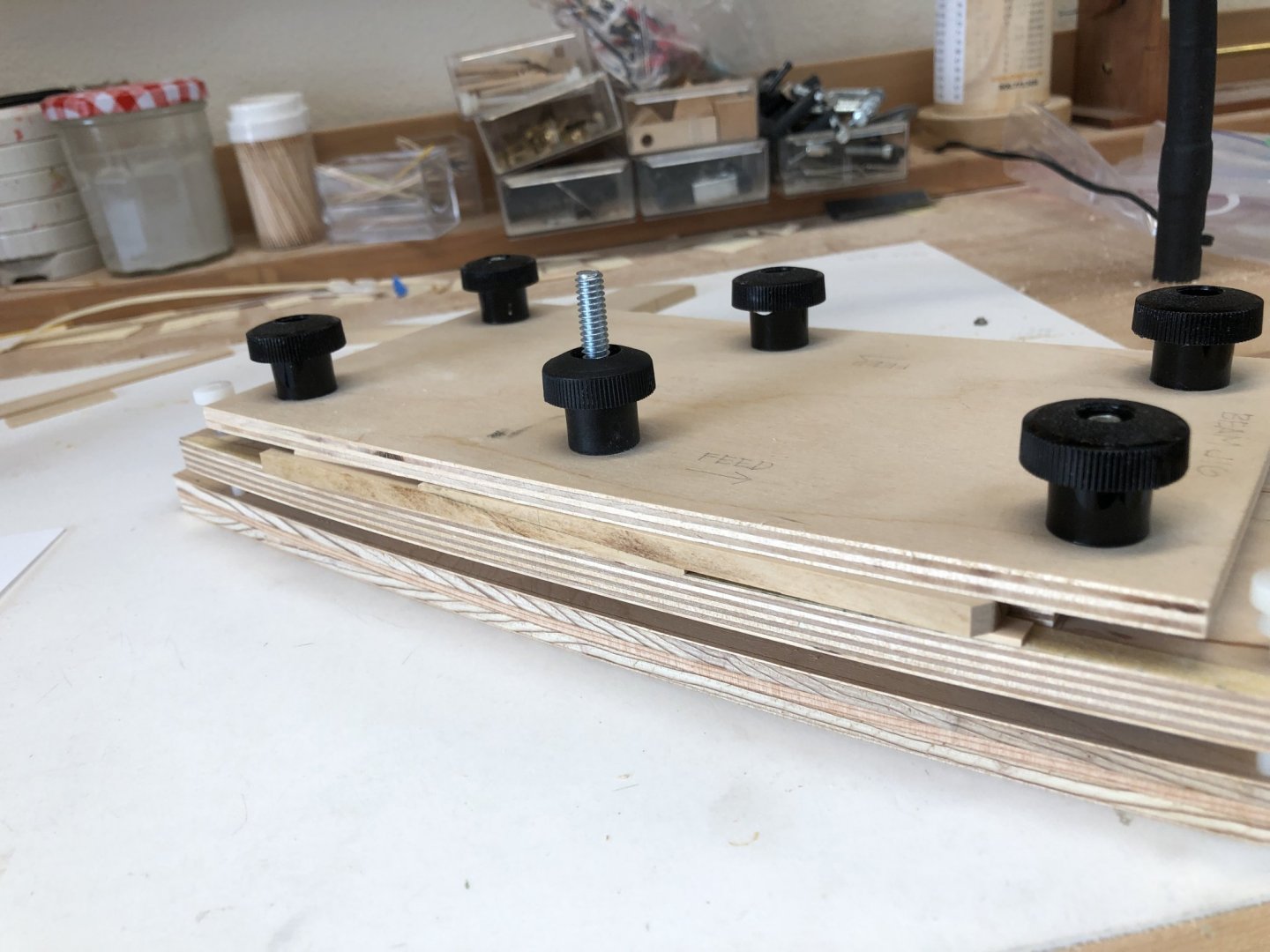
Hi JD, Yes, I used to live in Denver, a short distance from a Rockler Woodworking store. But now I am 850 miles away... I am glad you found the jig interesting. here are a few more details: The two template edges were formed by rough cutting the curve of the beam roundup, top and bottom, then using my sanding sticks of the correct radius to refine the edge. The sanding sticks themselves were made by cutting the arc of the correct radius through the middle of a piece of maple, then sandpaper was put on one surface to sand the other, and then the sandpaper reverse to sand the first surface. Gives perfect, smooth arcs. I then attached the template with hinges to the base that runs along the router table top. The white screws allow precise adjustment to the desired angle of the template for the sheer of the beam in cross section. Stops screwed down to the template are used to position the blanks before cutting. The edge of the stop on the convex edge of the template is straight, because the blanks are originally straight. I cut this edge first. The concave edge stop is shaped to the same roundup, because the just-cut blank now has the correct upper surface. The distance from the edge of the template on the concave side to the stop is the exact moulded size of the beam. I rubber cemented sandpaper on the template in front of each stop to give more friction to the clamping. A top sheet is then clamped down on the blank, with a temporary spacer at the opposite side of the template to achieve even clamping on the blank. Because it is so easy to insert things backwards in the monotony of doing the same thing over and over, I labeled each blank with which edge is the top curve, and also which surface should be up in the jig. I religiously check this before clamping the blank into the jig. And once the top surface is cut, I put the blank in the other side of the template and move the spacer to the other side. The angle is already set, giving perfect parallel surfaces to the top and bottoms of the beams. The router has to be adjusted for height for every cut, ensuring that the pilot bearing runs as close as possible to the top edge of the template. You can see in the diagram that if the pilot bearing were further down, it would cut further into the blank, messing up the thickness of the beam. For this I greatly appreciate the Rockler router table, which has an adjustment screw on the top of the table itself for precisely dialing the router up or down by small increments. Fiddly, maybe, but way less hassle than shaping every beam by hand. And also a much more precise way of dialing in the correct roundup and also angle for the sheer. Plus, it is fun to make jigs! Best wishes, Mark
-
I checked in on the Tally Ho project. I don't think I will get much work done while I look at all those videos! It is amazing to see in full size what we are doing at a miniature scale... Thanks for the reference to this! Mark
-
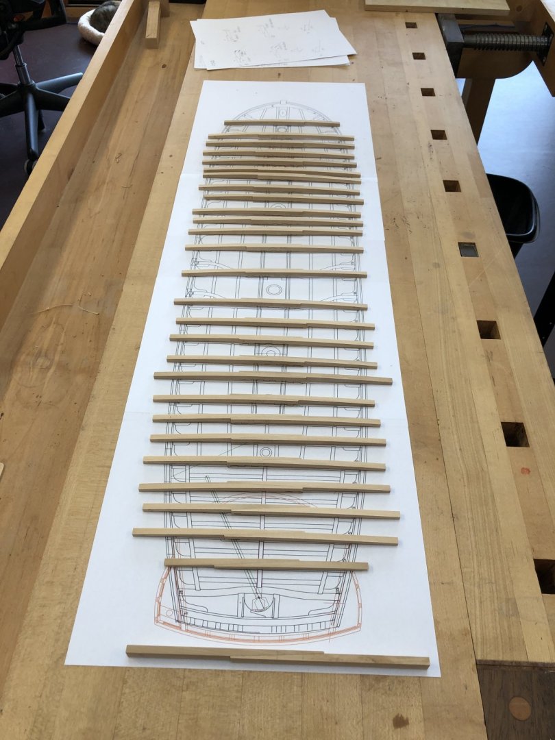
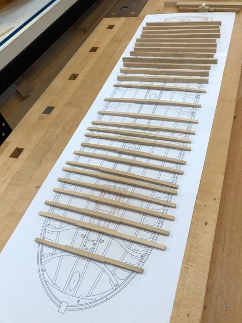
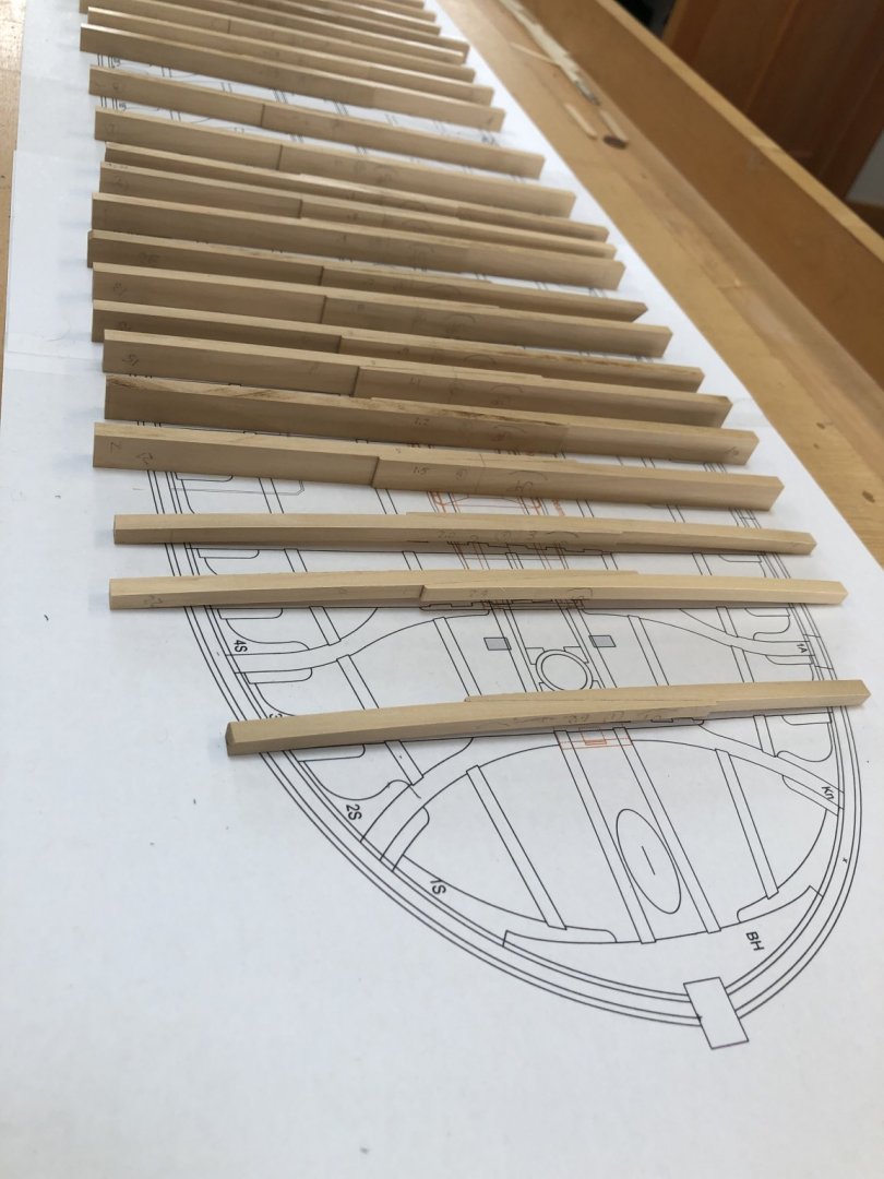
I improved my old beam jig, used years ago for the gun deck beams. It now has a base which runs along the router table surface. Hinged to this is a piece of plywood cut and sanded with the upper and lower deck roundup on each side. The piloting bit on the router table runs against this. an upper piece of plywood clamps down on the beam blank to hold it firmly in place. The hinge allows me to use a digital angle gauge to dial in the correct angle up for the sheer at the beam location. The white screws allow precise adjustment. So I first clamp in for the upper roundup, then switch to the opposite side to do the lower roundup. A spacer behind keeps the beam at its exact moulded depth. 3 done, 24 to go.....

-
Alan, nice drawing! I will file that away as well. Mark
-
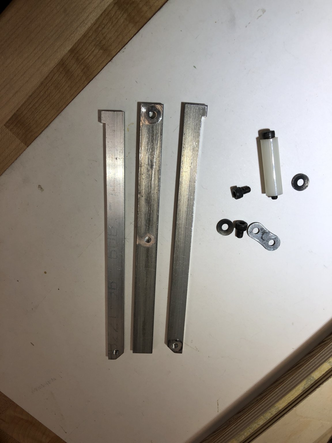
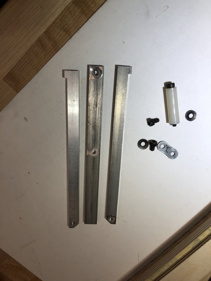
Hi Dave, Thanks so much! His design must have changed over the years, but the concept remained the same. I realize I had one too many pieces I was looking at, and here is how it goes together. Best wishes, Mark
-
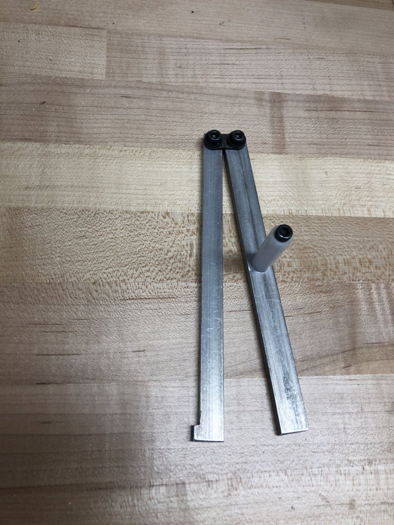
In my enthusiasm for needing some straight metal pieces for another jig, I took apart my old Preac saw taper fixture. Now I am ready to put it back together, I cannot remember for the life of me how this works. Could someone who has one of these post a picture so I can reassemble? Always take a picture before disassembling, I will remind myself in the future....🥴 Best wishes, Mark
-
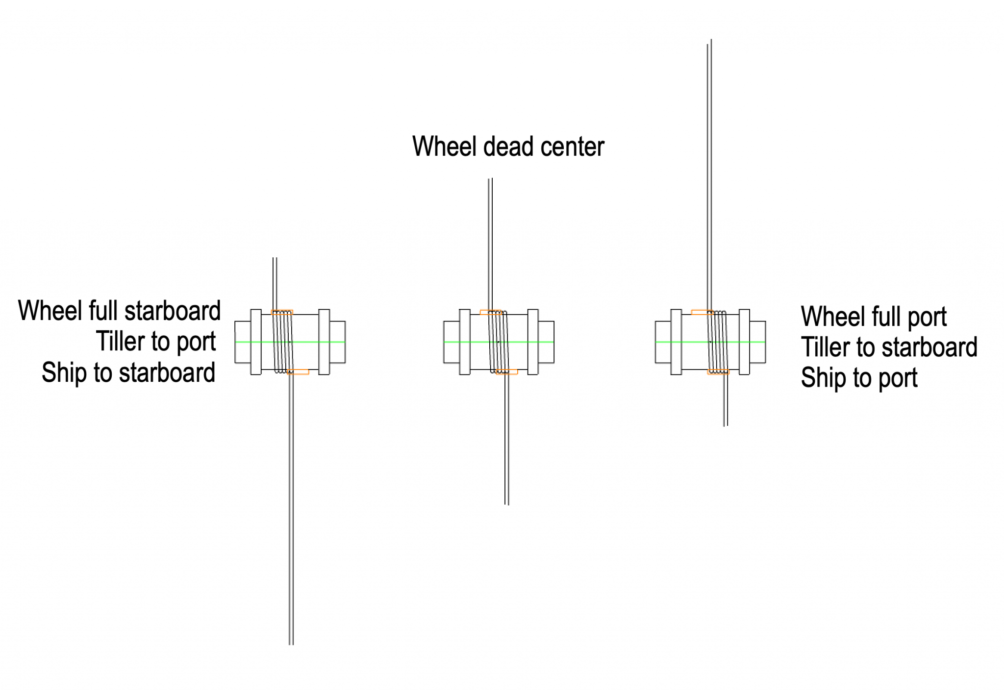
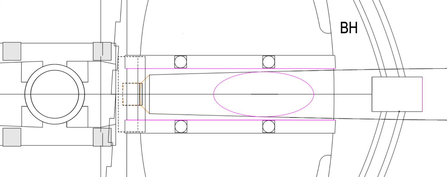
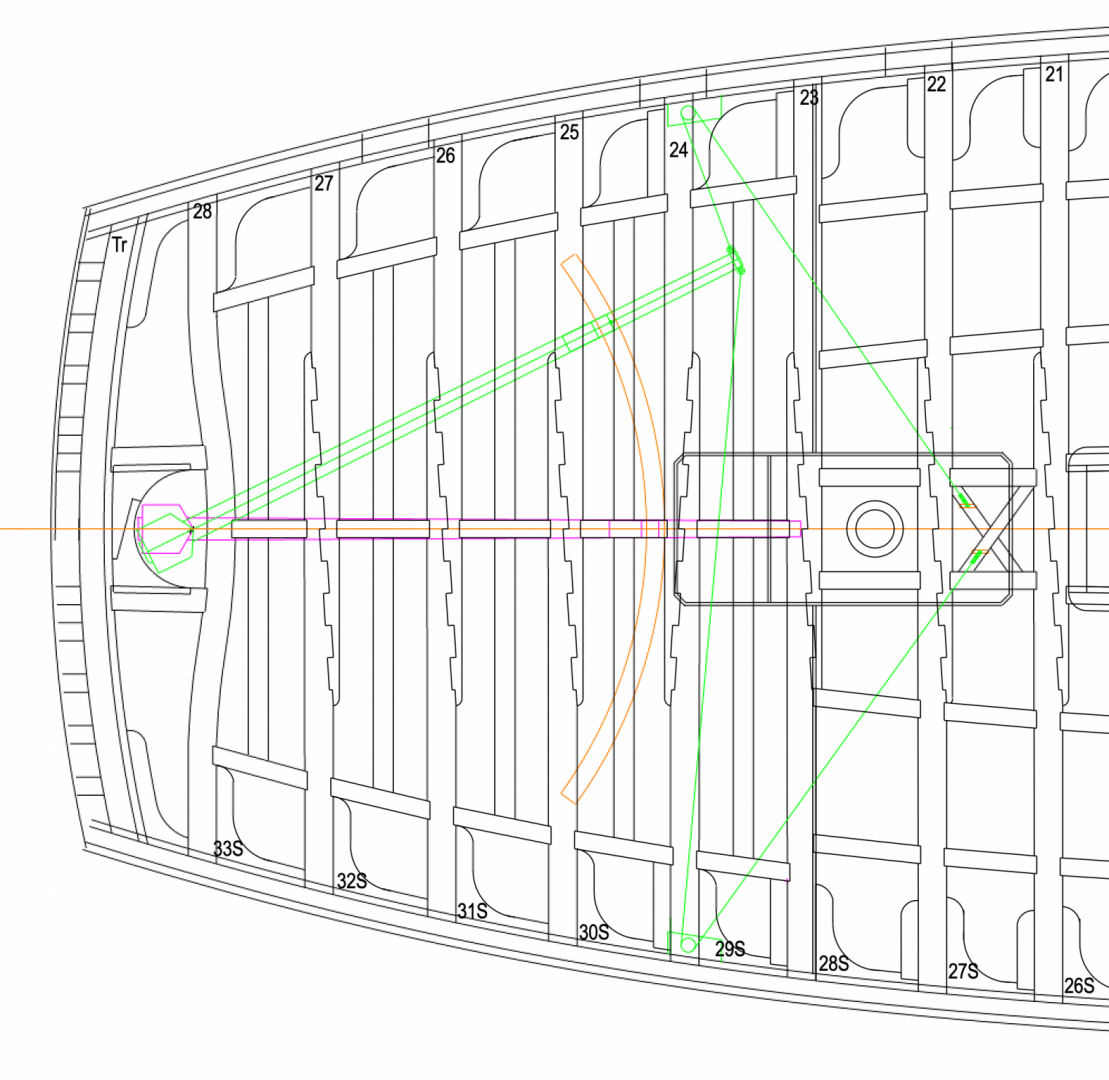
Thanks so much druxey and Siggi. I think, I hope, I have finally got it. Using primary sources closest in date to the Bellona, the Dorsetshire section and the Falconer dictionary, here is what I now see: The sweep is one beam astern of the end of the tiller, and the lines run to a sheave in the side, not to a free-hanging block, as in the Dorsetshire: And I will use five wraps on the hub, according to Falconer, which works perfectly with the maximum 2 full turns to each side or 4 turns lock to lock, with a fifth wrap for the nail at the center. This leaves a little bit shorter slot for the rope to traverse back and forth at the quarter deck level: And centering the sheaves in the upper deck framing on the center of each slot, we get: Back to shaping my upper deck beams! Mark

-
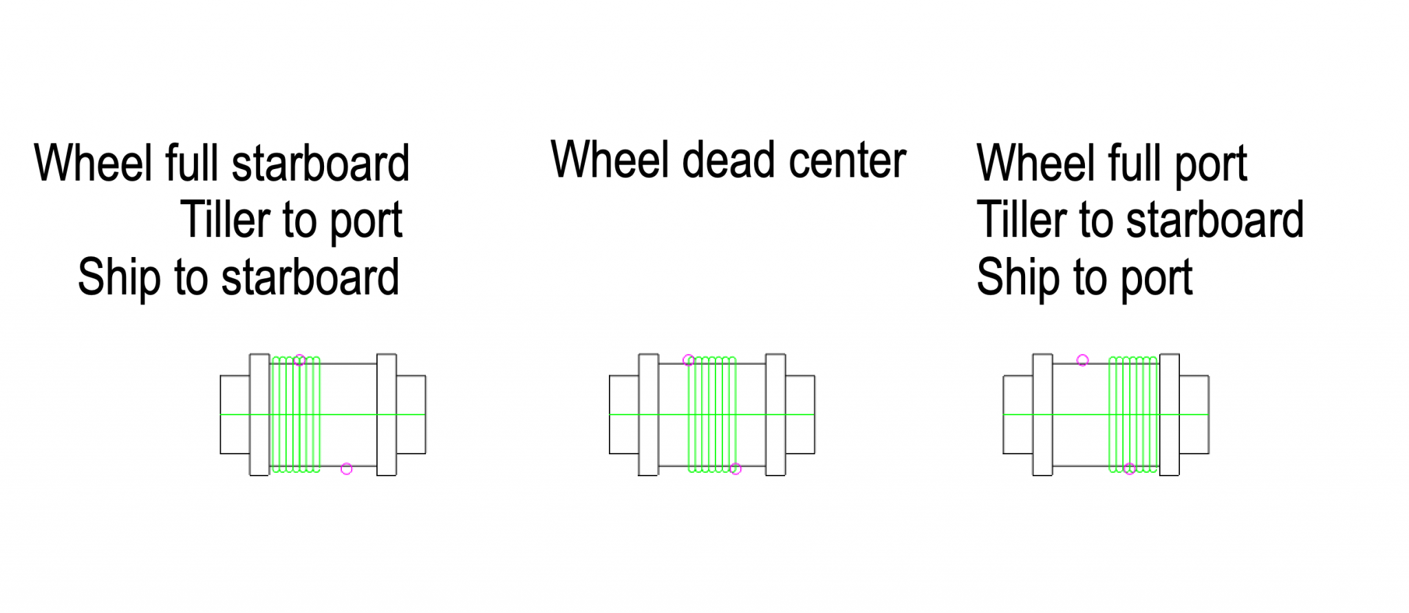
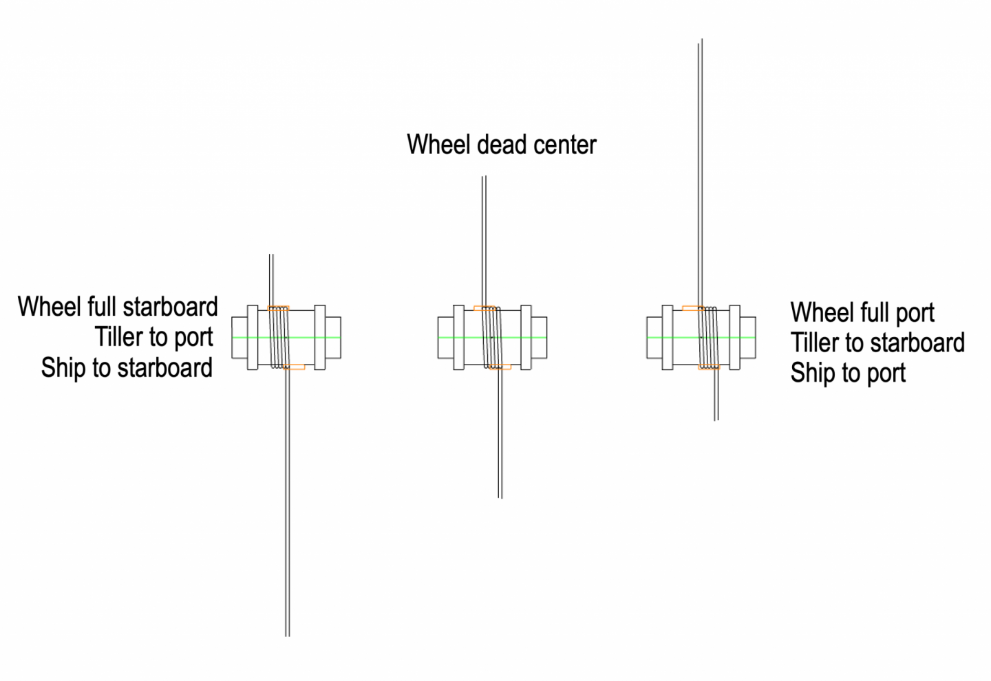
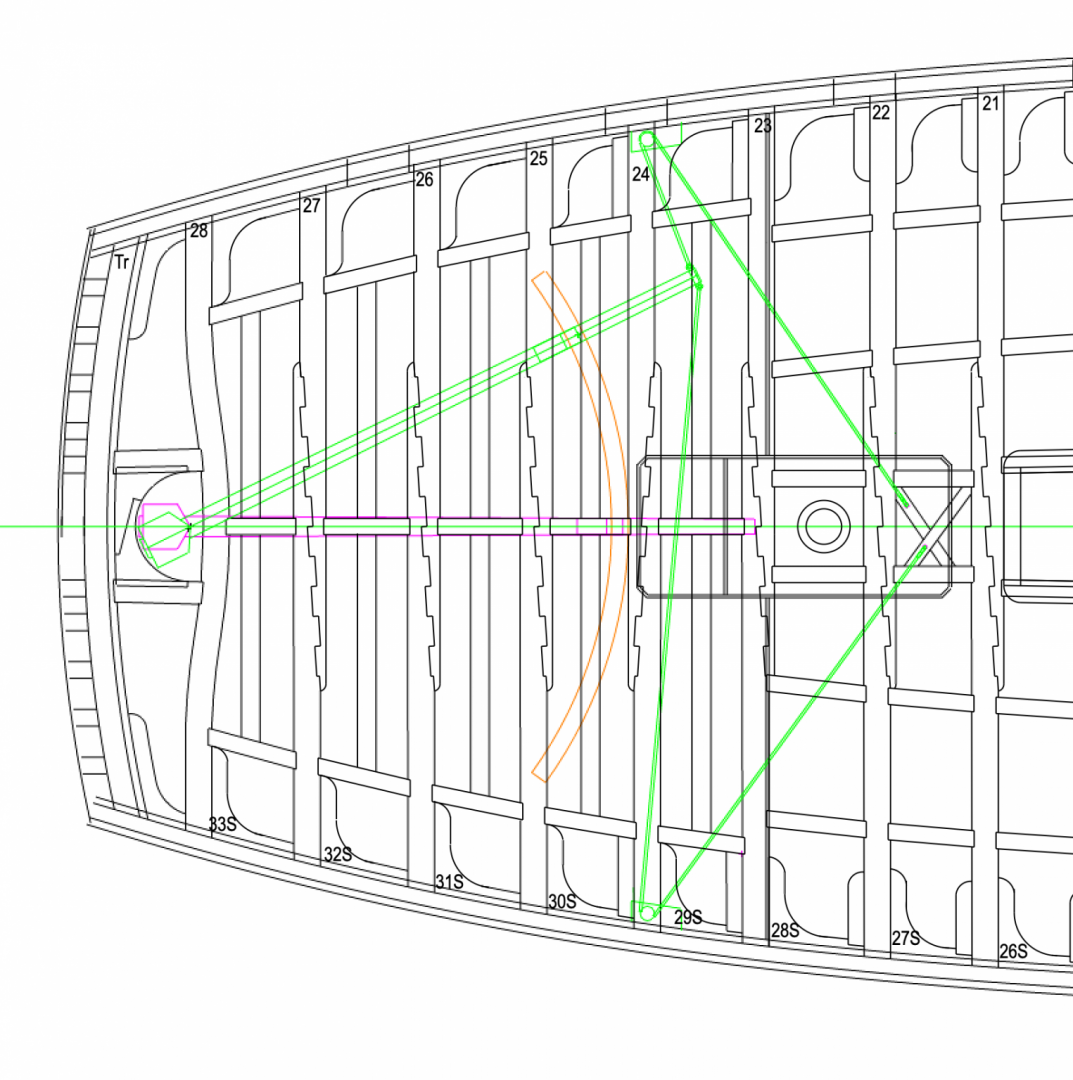
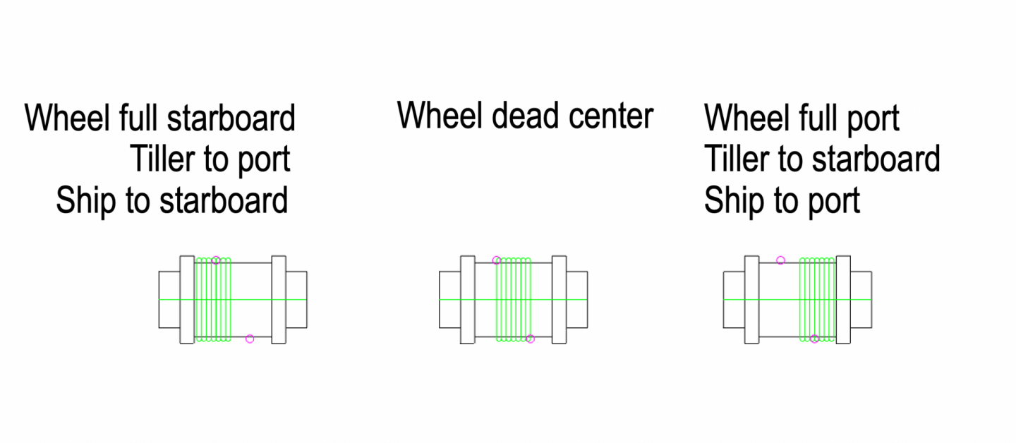
Thanks druxey and Gary. Gary, I see what you mean. Couldn't see it in three dimensions until looking at your stern. So I left the hanging knees out for now, will see how long my horizontal knees come into this space. druxey, fascinating little sketch of the wheel. First, I had the sheaves backwards relative to yours. I switched, and now I have the starboard sheave forward of the one on the port, as above. So I did my own calculations, based on your reasoning. With a barrel diameter of 21", one turn of the wheel pulls in 66" of rope. My tiller can only swing 10'-11" to one side from dead center, because of the gooseneck hitting the beam behind the sweep as discussed before. So I need 1.98 (rounded to 2) turns of the wheel to pull the tiller its maximum distance to one side, or 4 turns lock to lock. So, if I understand how this works, with seven turns around the wheel hub, the rope will move four rope diameters along the hub when turning from dead center to full port, and the same from dead center to full starboard. And turning the wheel itself to port moves the tiller to starboard and the ship to port. In the drawing below, forward is to the right. Assuming I have this right, I located the holes down to the sheaves in the deck so they are about equidistant from the two extremes that the rope on that side will travel. The purple circles are the locations of the holes down to the sheaves. Or would these be slots in the deck down to the sheave, allowing the rope to traverse its full four diameters? I understand HMS Victory had sliding plates allowing the ropes to move without a big slot in the deck; but I am not sure if this had been invented yet in 1760. So many unknowns! Mark
-
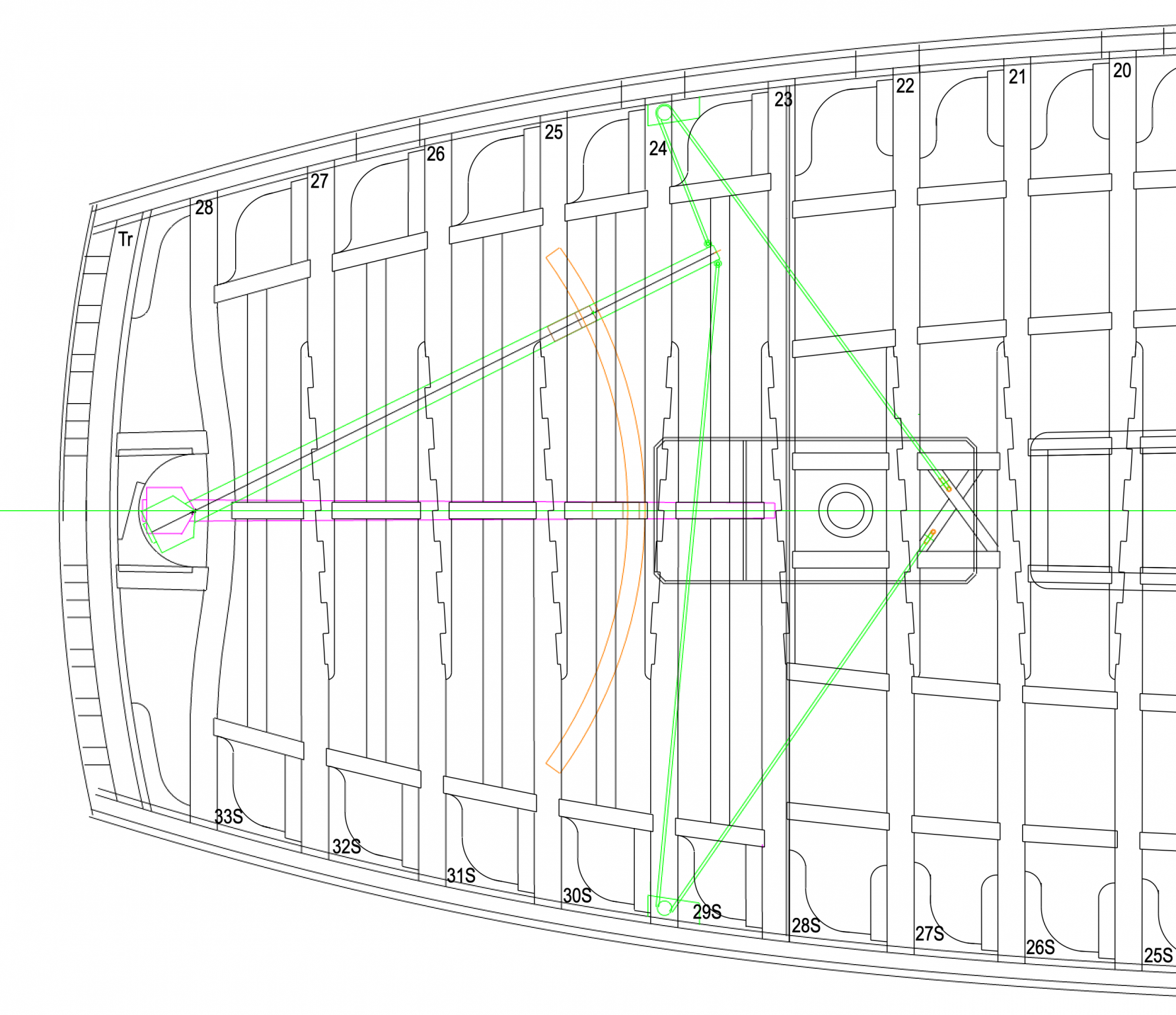
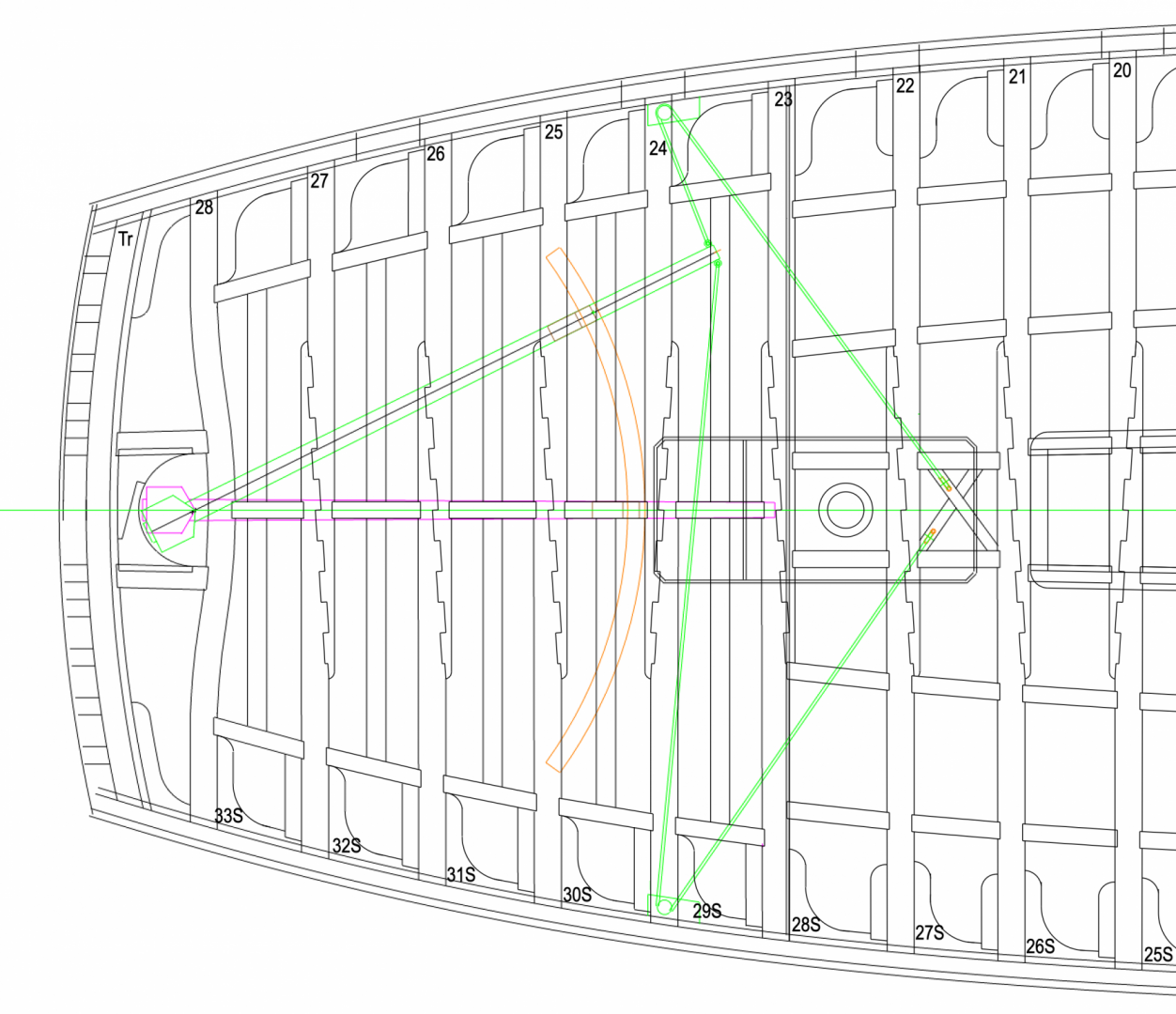
Thanks so much Gary, Mark and Siggi. You caught a mistake, and I was beginning to cut wood for the upper deck! Here is the refined version, thanks to your eagle eyes and research. My athwartship arms of the lodging knees were a trifle too long further forward, and the carlings at the stern were too wide apart. Adjusting for both of these, and the geometry comes out just right. I also fiddled with the geometry of the steering, moving the sweep back one beam, locating the sheaves at the sides according to the Dorsetshire print, and then running the lines to the steering wheel hub location afore the mizen mast. I worked out 7 turns on the hub, which located where the line comes up and then comes down, which are offset fore and aft by the width of the 7 turns. This makes the cross for the sheaves in the deck asymmetrical, as you can see below. Looks funky, but covered in decking eventually, so I guess I don't care! Am I understanding correctly that the port line up is the forward one on the steering wheel hub, i.e., the hub is wound clockwise? So a clockwise turn of the wheel would pull on the port line, which would move the tiller to the port, which would turn the ship to starboard? Hate to get it wrong, and have the helmsman accidentally steer into an obstacle! Mark
-
Sweet looking gundeck, Alan! I'll be interested to see how far your tiller can swing, assuming the sweep and gooseneck are up in-between the beams as I see in the Dorsetshire plan. It is the gooseneck hitting the side of the aft beam that ultimately limits the rudder swing in the Bellona, not the size of the rudder hole in my case. Mark
-
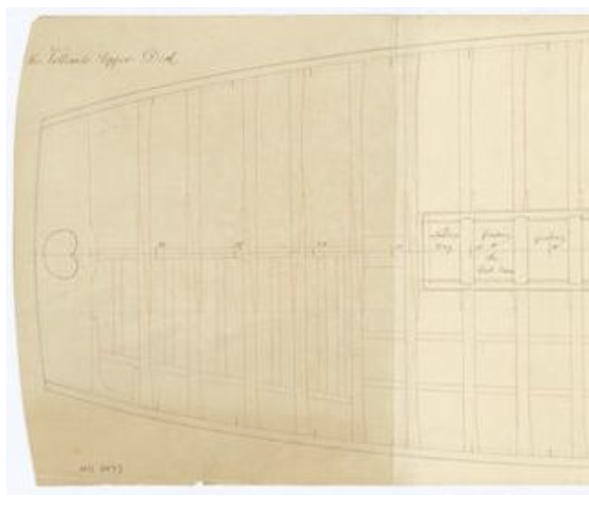
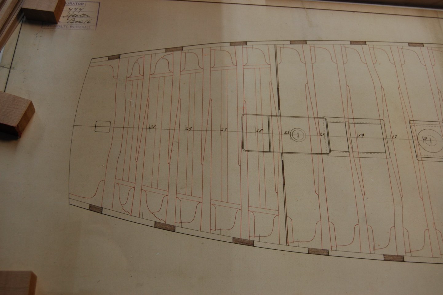
A little more digging last night, and I remembered that I was looking at HMS Valiant (1759). I saw this in Brian Lavery's "Building the Wooden Walls: The Design and Construction of the 74-gun Ship Valiant". The Valiant, according to Lavery, was begun the same time as the Bellona, as a substitute at the last minute for a Dublin class 74 that was about to start construction. So this deck plan would have been at least one way of constructing the upper deck of a 74 at the time of the Bellona. Assuming the athwartship arm of a lodging knee reaches from the side to the carling in the middle section of the deck, then these carlings set closer to the side for the remaining 5 beams would either require their knees to be shorter, or for the heads to be cut off, as I have shown above. I will try drawing some shorter knees in this aft section, and see if that looks more shipshape. Mark Detail of Valiant upper deck, from https://collections.rmg.co.uk/collections/objects/384159.html
-
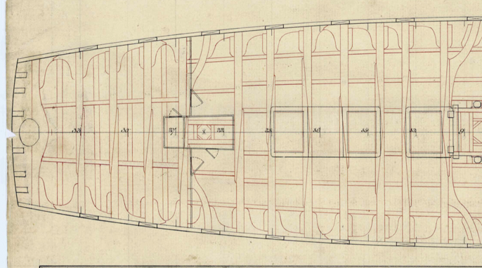
Hi everyone, Well, this is embarrassing, I can't find the plan I was looking at when I drew my upper deck. I assumed it was the Dorsetshire, but here is the Dorsetshire: I need to keep looking through my various sources. Should have written this down years ago. But if I don't find the source, the drawing Gary showed of the Hector, with the carlings moved in to the heads of the knees does make sense. Thanks for flagging this Siggi! A little more digging to do.... Mark
-
thanks so much, Gary and Siggi. That makes perfect sense. It is confirmed by the section of HMS Dorsetshire from NMM, below. Here the sweep and gooseneck are clearly in between the beams, and also one beam back as you suggest. This shows what looks like a sheave in a fixture in the side, not a free-hanging block as Lavery shows in the Bellona book.... It doesn't allow any wider swing of the tiller, but it fits constructionally.