HOLIDAY DONATION DRIVE - SUPPORT MSW - DO YOUR PART TO KEEP THIS GREAT FORUM GOING!
×


SJSoane
-
Posts
1,649 -
Joined
-
Last visited
Content Type
Profiles
Forums
Gallery
Events
Everything posted by SJSoane
-
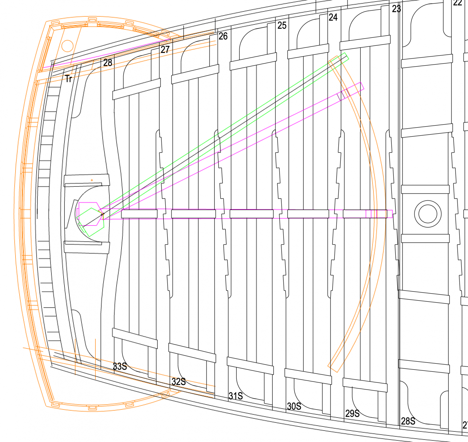
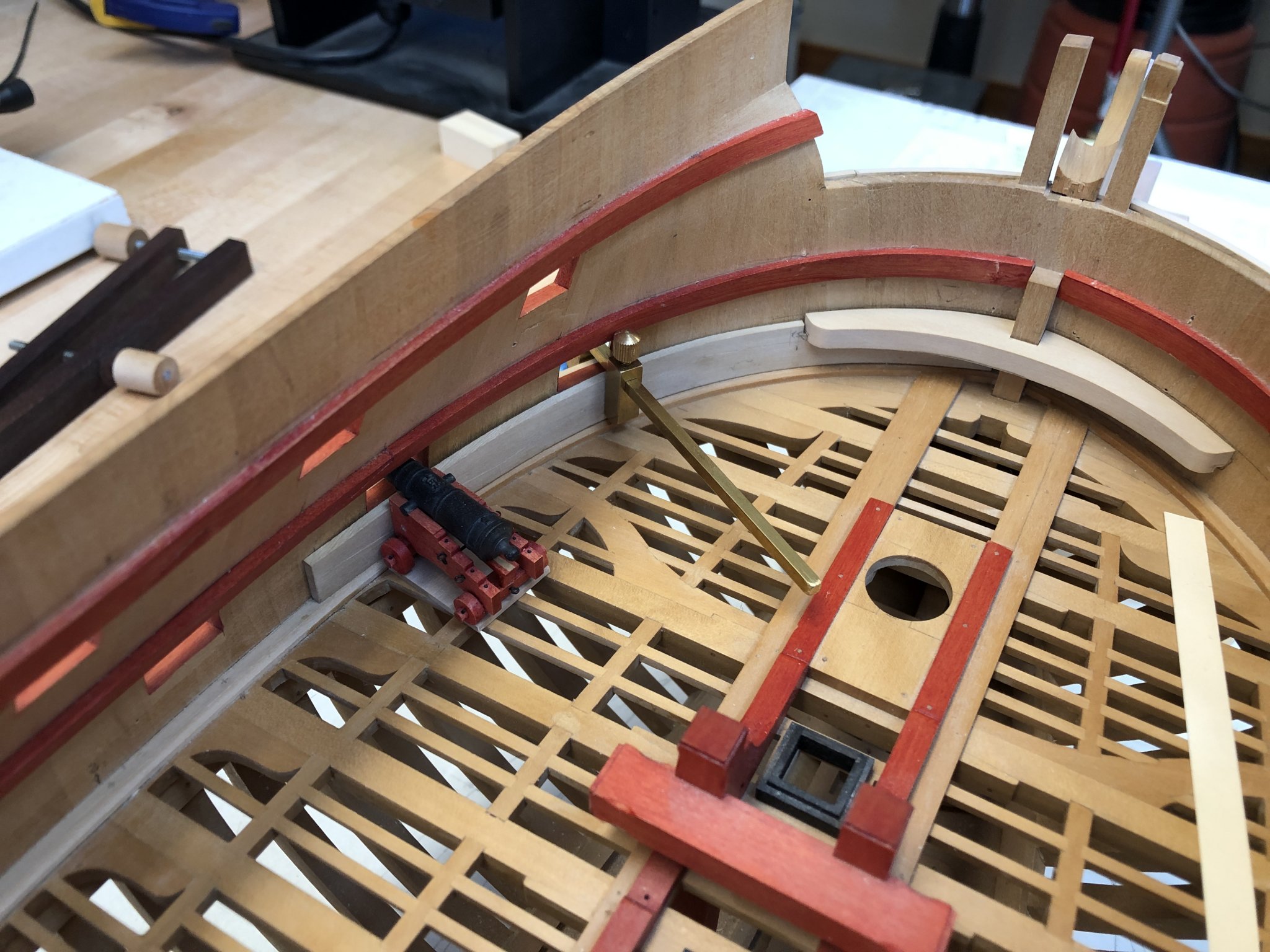
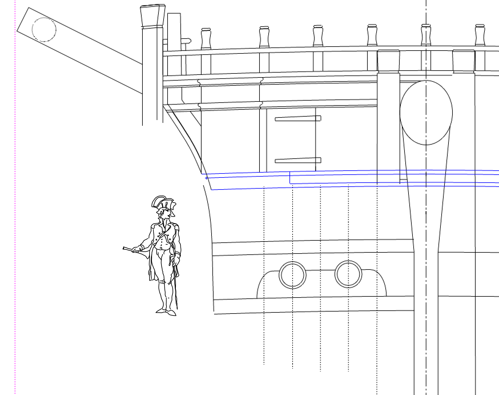
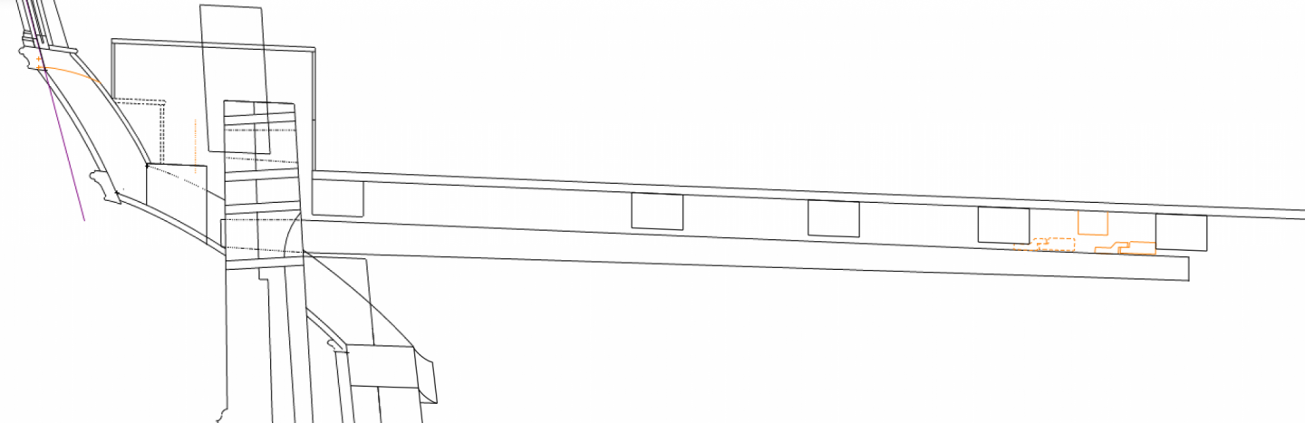
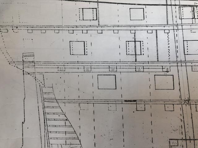
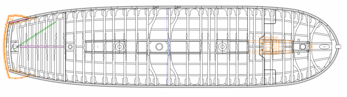
 Hi everyone, While waiting for the upper deck beam glue joints to dry before shaping their roundup, I worked some more on the tiller and its tackle. In a post to Alan (AON)'s site, Gary (garyshipwright) pointed out the need for directing the wheel ropes up through the deck forward of the mizen mast. I started working on this and discovered a few things. First, according to Brian Lavery's Arming and Fitting of English Ships, pp. 18-20, at the 1760 date of the Bellona, the Royal Navy was holding up the fore end of the tiller with a gooseneck running along a curved sweep track, just under the upper deck beams. A rope ran from the end of the tiller to a block on either side of the ship, back to a central block and up to the steering wheel. A problem with this method was that the tiller rope did not equally tighten and slack on each side of the tiller, causing sloppiness and some accidents. The solution was found in 1771, when Pollard, a Master Boatbuilder at Portsmouth devised a way to run the tiller rope along rollers within the track itself, keeping equal tension. But this was 20 years after the Bellona, so I will have to model the earlier, cruder method. And here it gets interesting. the original Bellona draft shows the tiller very tight up against the upper deck beams. We are seeing below the tiller at midships, but the beams at the sides. When the beams are shown at the center location, their bottom surface is only an inch or so from the top of the tiller surface. How does the gooseneck and the sweep fit? Here we see close up that the gooseneck and sweep cannot fit under the main beam. Both have to fit up into the space between the beams. There is more clearance at the small intermediate beam shown in orange. but eventually as the tiller sweeps to the side the gooseneck (shown in dotted orange) it hits the next big beam aft. (this drawing is not accurate for the position up and down, since the tiller sweeps downward as it sweeps to the side, following the roundup of the deck beam. But the space between tiller and beam will remain the same through the sweep, so this is just showing that eventually the gooseneck hits the beam.) In plan, this means that the tiller can only swing as far as the location shown in purple. The green location is a 33 degree angle David Antscherl discovered as the ideal angle in a study of helm angles in the eighteenth century, and described in The Fully Framed Model, vol. II, pp. 47-8. The Bellona geometry only allows a 26.7 degree sweep. However, the contemporary study David quotes also notes that some ships in the period only swept 28 degrees. So maybe this is close enough. There really isn't any lee-way, given the restricted space between beams 23 and 24, into which the gooseneck and sweep have to fit if the tiller really is as tight to the beams as the original Bellona section shows. Even with this, the sweep will have to be pared down at its outer ends to fay onto the underside of beam 24. Mark
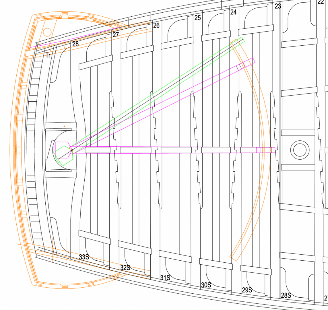
-
Gary, thanks for the note regarding how to handle the tiller ropes. I would have been in some difficulty getting around a central carling a few months down the road. Isn't it great to share ideas on this website! Mark
-
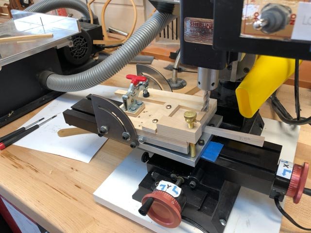
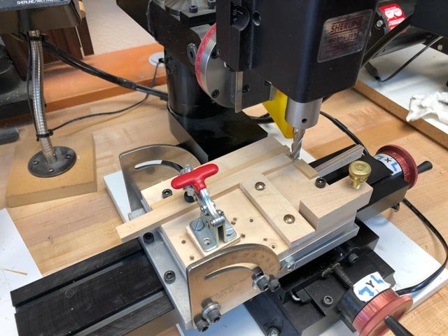
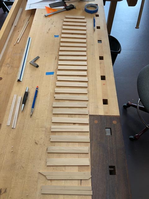
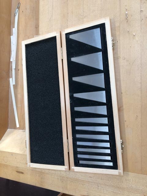
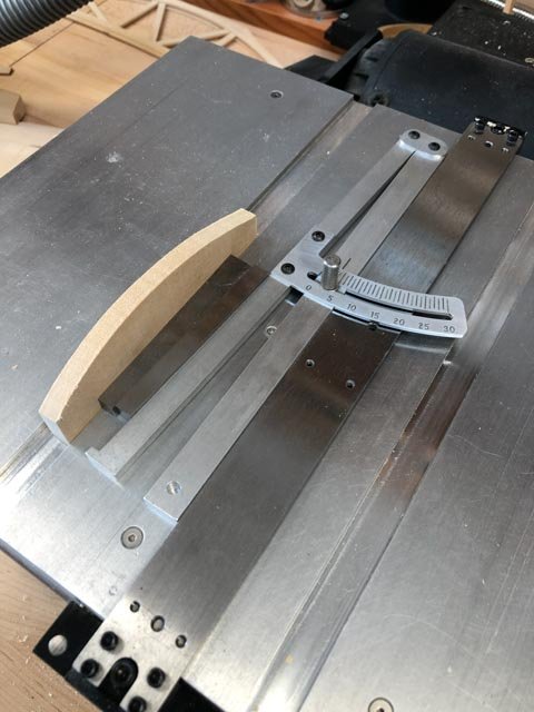
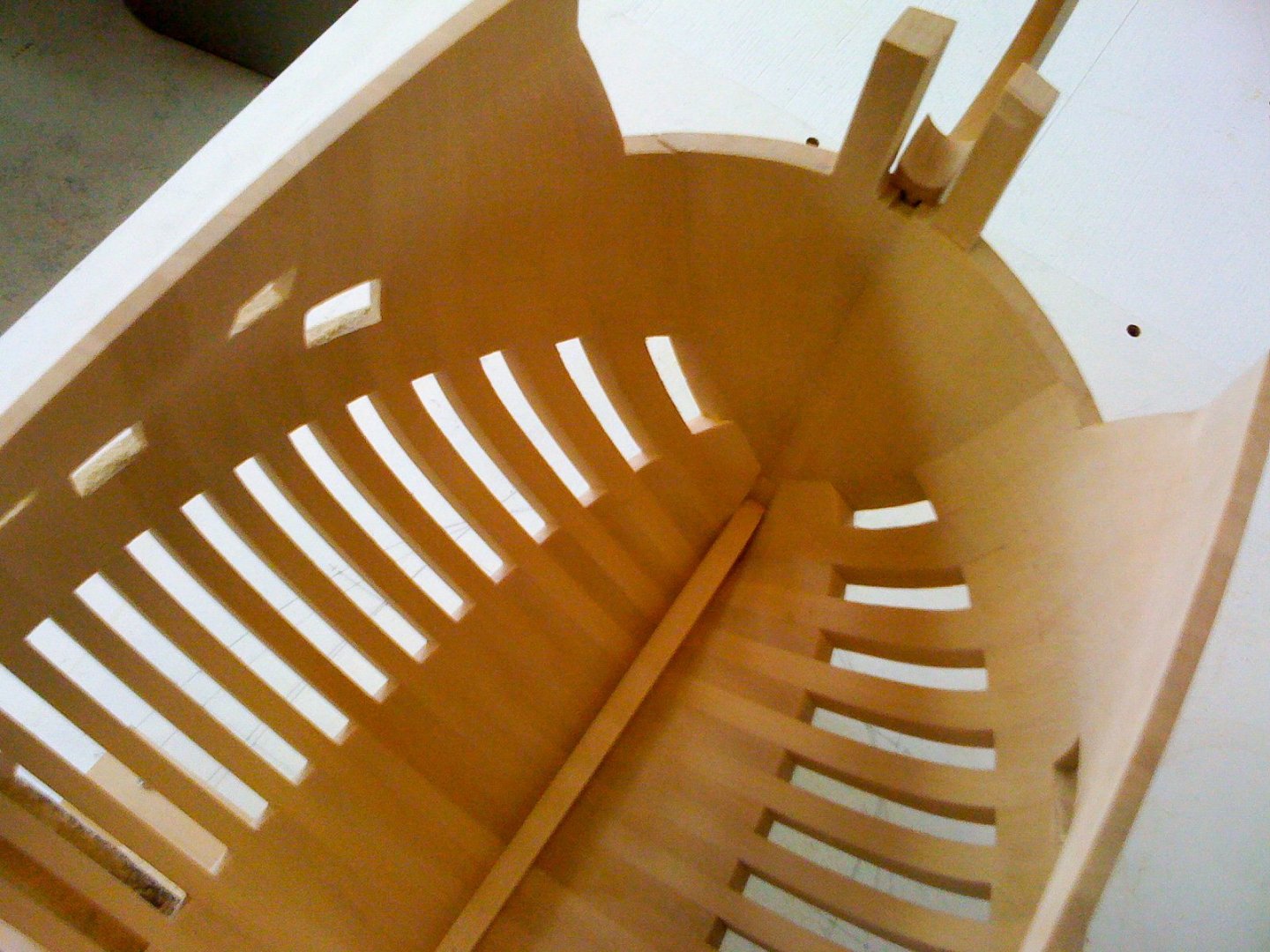
I realized that other day that summer is coming to an end, and cold weather will be upon us before we know it. That means I need to plan ahead for anything needing the use of the router table in the garage before it is too late. So, I temporarily put aside spirketting, to concentrate on making the beams for the remaining decks. I used a router jig for the gundeck beams, and plan on the same idea for the rest of them. First, the upper deck beams. Much as I admire the tabled joints done by our great craftsmen including Gary (garyshipwright) and Ed Tosti, I remind myself that my design goal is to emulate the Admiralty style models I can see close up including the two Bellona models and also the Princess Royal model in Rob Napier's book. My hull framing is thus stylized, and so should the deck beams as seen here in my photo of the first Bellona model. The two beam halves are a simple scarphed joint. I did this on the gun deck, and so will continue onto the upper deck. The higher decks are one piece beams. So, I measured the angle needed to form the correct length of the scarph, and used angle gauges of 3.5 degrees to set up the table saw for an angled cut: I then slid this angled plywood piece under the angle table on the Sherline mill, to set the correct angle of taper. On top of this I bolted a simple holding jig, into which I can slide beam blanks, clamp them down, and then run the cutter across to form the angle. The brass bolt was used for fine tuning of the angle after I ran some tests for the correct length. I have 27 beams in the upper deck, times two halves, times 3 passes for controlling the depth of cut, equalling 162 passes of the cutter. A happy five hours! Here are the blanks awaiting their turn at the mill... Next, gluing up and shaping the roundup on the router table. Mark
-
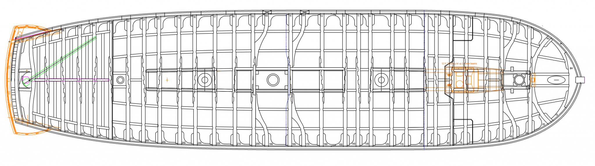
Hi Alan, Just for fun comparison, here is my reconstruction of the Bellona upper deck. Now I am going to have to remember where I got the carling pattern, which steps towards the bow and stern, also the curved beam just forward of the rudder opening... Mark
-
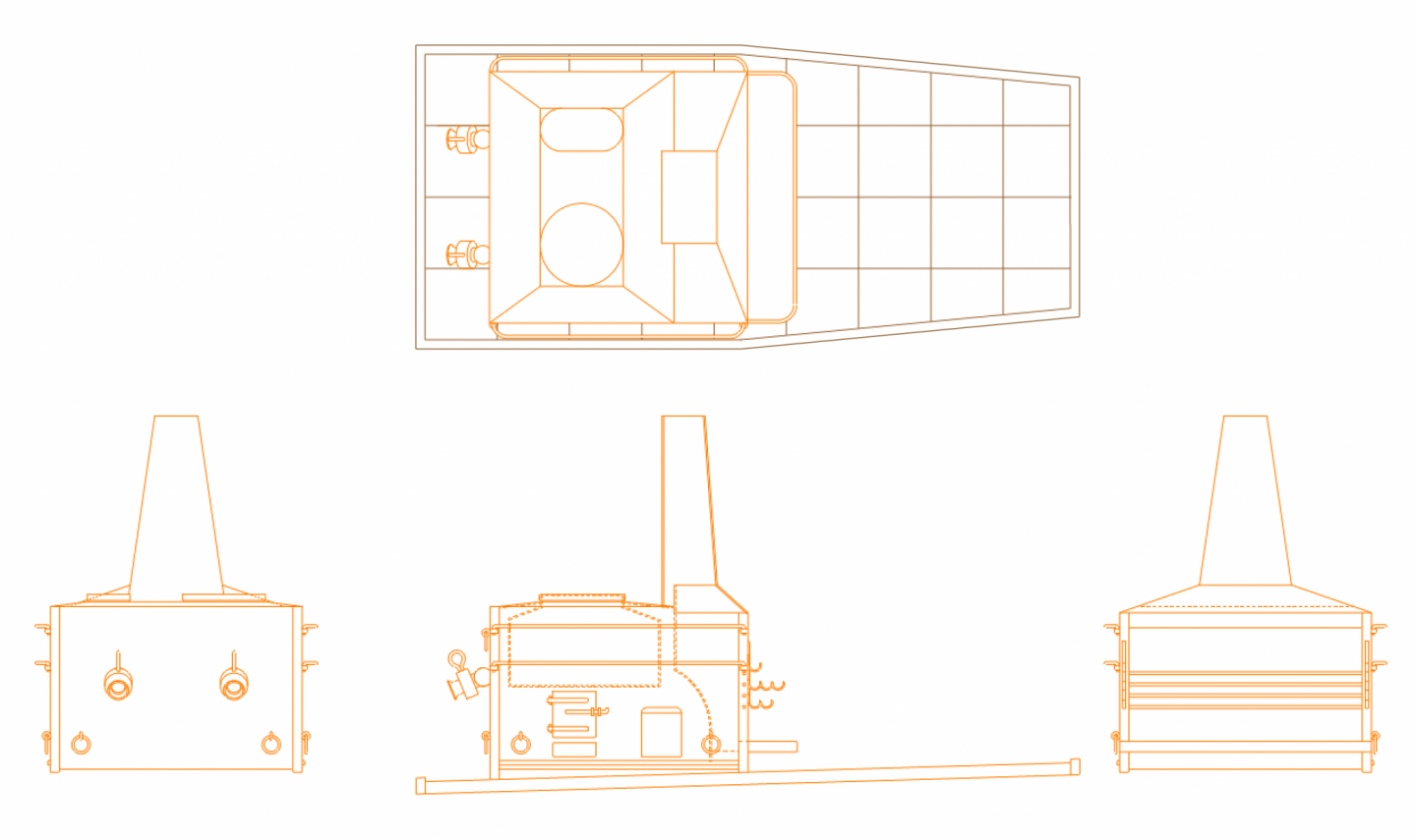
Thanks so much, druxey and Gary. I am very slow but steady! Waiting for glue to dry on the starboard spirketting at the bow, I finished up the drawings for the pre-Brodie stove. Given the material I found, this is my best guess. It may be a few years before I actually get to construct it, so I may find out more before I begin. It is intriguing, in the Dorsetshire drawings, the nozzles out of the kettles seem to have a ball connection between the fitting and the side of the stove. They are clearly a ball in the drawing, with shading to indicate it as such. I wonder if this was a rotating fitting, allowing the nozzles to change their direction left and right and up and down. Don't know why this would be of value. And my "squiggly thingies" are drawn to the scale of the Dorsetshire drawing, but they do look flimsy for carrying a large joint roasting out at the outer edge. Maybe these need to be thickened up a bit. Mark
-
And think about how those little guys swayed up 4 or 5 story tall baulks of timber, located to within a fraction of an inch in some cases. Astonishing what they could accomplish before power tools. And the model is looking great, Gary! Mark
-
Alan, Congratulations on the successful surgery! Mark
-
Interesting to see how firewood is both stored and used to support the barrels. Very clever! Mark
-
Looking nice, Mark! Mark
-
HI Gary, doesn't it feel good to be ahead of Wikipedia!🙂 And by the way, I was pointed by Alan (AON) to your posting on your stove, which I haven't looked at for some time. You did an an outstanding job on that, an inspiration! A small update, but important to me. I finally installed both the spirketting and the quickwork on the port side of the bow. The quickwork was challenging, in having to fit between two existing pieces, with no room to maneuver, while at the same time dealing with constantly clamping to the curve as I tried to fit it. But it came out OK, including scribed planking you can just see. I have also temporarily put in the hawse hook, just to see the area where the hawse holes will finally come through. A couple of routed rabbets provide slots for the spirketting and quickwork to slide behind the hook while still leaving a surface for the hook to butt directly against the frames for a positive gluing connection. Mark
-
Hi druxey, I think whenever possible, we should use proper technical terms like "wiggly thingies". It helps with clear communication!😊 Mark
-
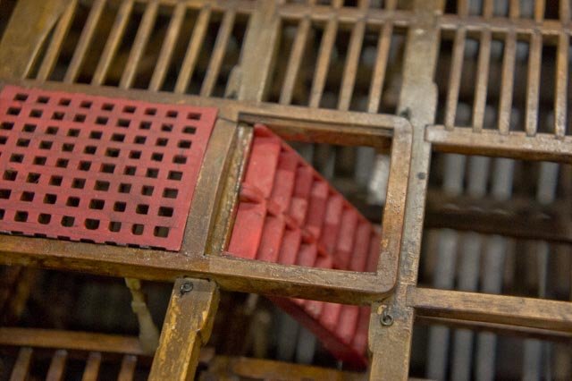
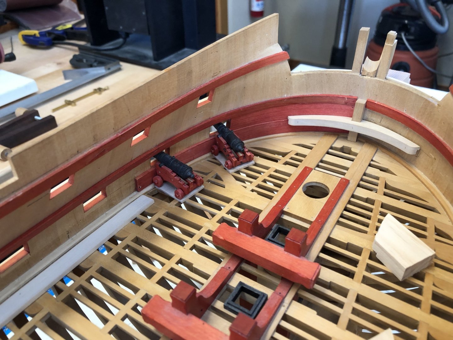
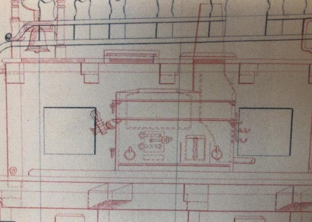
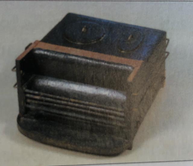
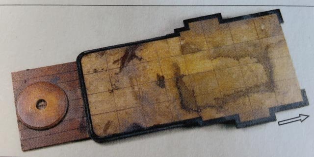
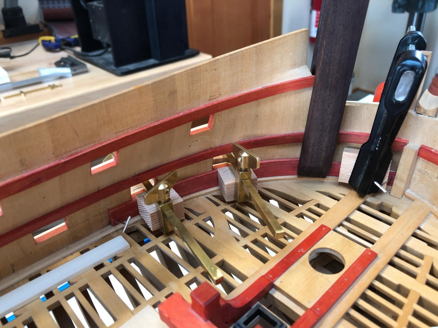
HI eveyone, Working away. I have installed the foremost port spirketting, using the idea from Rob Napier of SWOPEM (Situation Where One Piece Equals Many) in 18th century ship model construction. You can see the hooked scarfs inscribed in the single spirketting piece, which allowed me to fit and stain this piece outside the model, then install for a clean line to the waterway. I will hide the vertical joints between these large spirketting pieces behind the standards. Clamping was challenging; I made a shaped block for the outboard side at the centerline, which hooks over the stem to keep it in place while placing the clamp. I also had to use some pins in hidden places to keep the piece tight to the stem and to the waterway while putting the clamps in place. While waiting for stain and glue to dry, I continued to work on the stove predating the Brodie stove. Here is all the information I have on my NMM plans for the Bellona ca. 1759: It matches almost exactly in dimensions the stove shown in the NMM plans for the HMS Dorsetshire of 1757, which has more detail. Check out the massive nozzle to the left: Note in both cases the 4" substance sitting between the stove and the deck below. Mark P.'s original contract from this pre-Brodie stove period clearly calls for a lead-lined tray shaped at the edges by cants around the stove, and says nothing about brick. Looking at the model of the Princess Royal of 1773, 20 years later than the Bellona but a little before the Royal Navy switch to the Brodie stove, the model indicates what Rob Napier interprets as masonry on the base, painted this nice cream color and with a roughly 1 foot square paving pattern (see below). But also notice that it has a black cant around the outer edge. This seems to accord with the drawings of the Bellona and the Dorsetshire. So I wonder if the brick sits over the lead tray but was not mentioned in the contract, or if there were several ways this was done before the Brodie stove, sometimes with lead only, sometimes with masonry. Given the certain information of a contemporary model that is consistent with my Bellona drawing, I have decided to go with this attractive cream colored base. Whether it is masonry or not I will leave to the imagination of the viewer! Now, on to some interesting details at the roasting end of the stove, on the right side of the elevation. In the Dorsetshire drawing, the fire grate for the roasting area sits to the right and at the base of the dotted curved line. It appears to be open all the way up to where the chimney starts to angle in. Right in the center of this open space appear to be four horizontal round bars seen as circles in this elevation. We can also see these in the Rob Napier's photo of the Princess Royal stove, below. The location of these would seem to prevent the use seen later in the Brodie stove of arms that can be swung in and out of this fire for holding pots. Indeed, the Princess Royal stove seems to show a shallow pan at the top of the horizontal bars; was this for frying? The pan does not show in the Dorsetshire drawing. Also, note in the Dorsetshire drawing 3 wiggly shapes projecting out from the face of the fire, with one, three and then two hooked shapes for holding a horizontal spit bar or bars, perhaps? they can's swing in over the fire, since the bars are in the way. Did they roast on spits hanging at different distances from the fire, to control the heat? There is definitely a tray for drippings under all of these spit bar holders. So were these wiggly projections just bolted onto the sides of the stove, like the simpler spit bar holders in the later Brodie stove? That will be my best guess at this point. All for now! Mark
-
Hi druxey, I will try that if this first effort proves too difficult to pull gracefully into place. Even the 3 1/2" quickwork needed steaming at this point, so I would steam both layers separately, then laminate. Has possibilities! Good idea on the church roofs; I'll look at some old photos to see a seaming pattern. Makes sense it would be the same process. Mark
-
Thanks, Mark, that makes perfect sense. It also explains why the stove seems just a little too short if it stopped at the top of that line which we now know is the line of a cant. Short, because there needs to be more room below the door to the kettle fire grates, for an ash tray and a space for air to get into the fire. So I will assume that the sides of the stove actually go down to deck level, with perhaps slots in the ends to admit air into the entire structure under the fire grates as in the Brodie stove a few decades later. Do you think the lead was laid in long strips fore and aft, or overlapping tiles of lead like the copper sheathing on the hull? All rolled seams in the metal, I presume. Best wishes, Mark
-
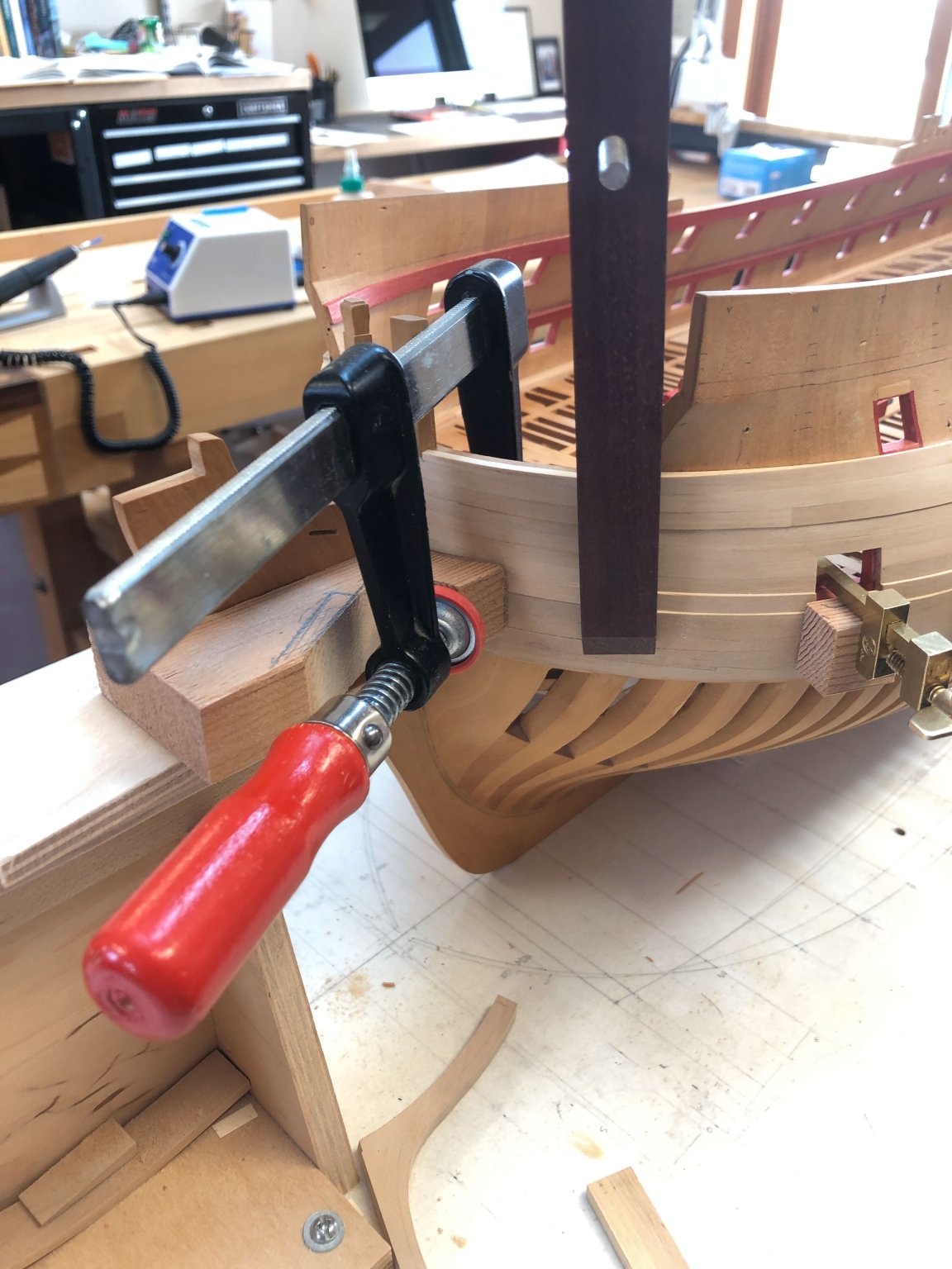
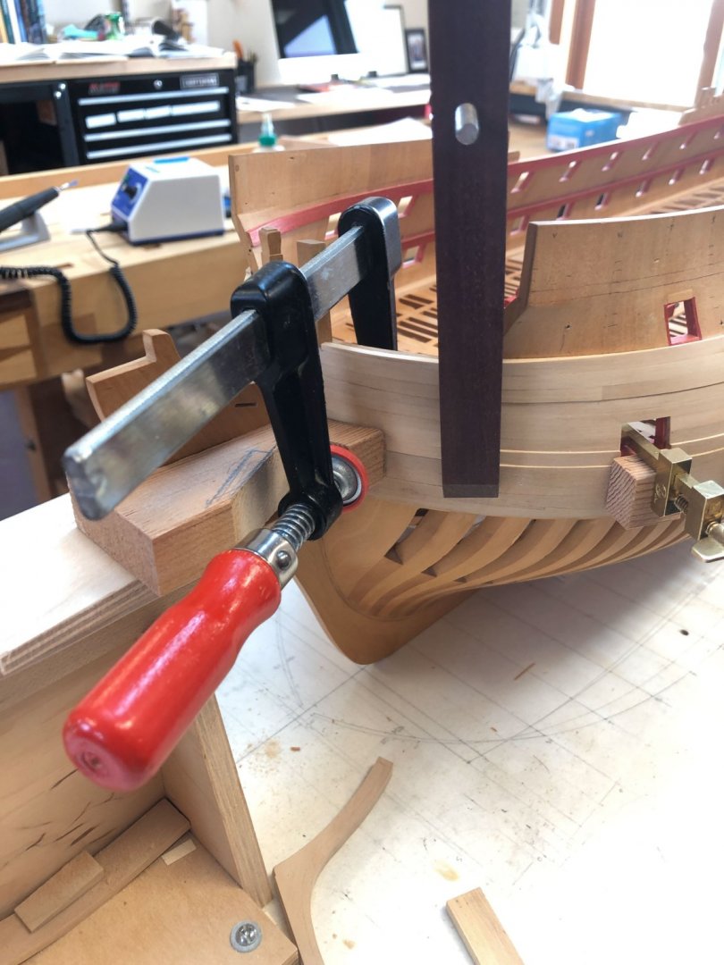
While pondering the lead question, my steaming dried. Here is a first look at the spirketting challenge. I faced a chicken and egg problem. the two strakes of spirketting would need to be glued in before their surfaces could be dubbed down smoothly; but once glued in, the red stain would be exceedingly difficult to keep from running onto the waterway. I looked again at Rob Napier's Legacy of a Ship Model, which showed an eighteenth century model of the Princess Royal in exquisite detail as it was pulled apart and put back together. I discovered a neat trick used often by the 18th century model builders, which Rob Napier named SWOPEM; "Situation Where One Part Equals Many" ( p.42). One piece is scored to look like a number of parts joined together. I am exploring whether I can make this work for the spirketting, using one band and scoring for the scarps joints. This keeps a smooth surface, which, once fitted to the waterway and cut to the sills of the ports above, can be stained and then installed in one go, no dubbing down needed. I figure if it was good enough for the 18th century model builders, it would be good enough for me, particularly when it will be buried deep in the ship when two more layers of decks go on. An additional challenge of this is that my wood notoriously has strong springback after steaming, particularly with this 6" thick piece. So I am experimenting here with holding the spirketting at the bow within a rabbet in the lower face of the hawse hook. This will act as a natural clamp to the spirketting. keeping everything fair. In the photo below, I still need to sneak up the vertical cut in the spirketting to the port edge of the hook, for a tight fit. This is again a modeling cheat, because the hook in the real ship sits on the face of the spirketting and quickwork. But no one will see the difference, and it helps with tidy construction. All for now! Mark

-
Thanks, so much, everyone. Mark, it is so nice to have primary evidence in the way of these contracts. According to an online calculator, 7 pounds of lead equals 18 cubic inches, which spread across a square foot according to the contract would be an eighth of an inch thick. I wonder what the extra thickness is in that cross section of the Dorsetshire, which looks to be somewhat thicker than the 3" deck below it? I did confirm on the National Maritime Museum site that the Dorsetshire drawing Brian Lavery redrew does indeed show this extra line of thickness. Could the deck just be thickened up with another layer of wood decking under the stove and lead, for structural reasons? This is way more fun that watching steamed wood dry... Mark
-
Hi Tiziano, Beautiful, crisp craftsmanship. You set a high standard for all of us! How do you blacken the joints between the deck planks? It is pleasingly subtle. Best wishes, Mark
-
HI Gaetan, I am impressed with the photos from your smart phone, particularly how you kept so much in focus across a large depth of field. My efforts usually result in a much shorter depth of field, leaving a lot out of focus. Do you places the focus at the center of the image, or front or back? And by the way, the model is looking quite wonderful. Beautiful craftsmanship, as usual! Mark
-
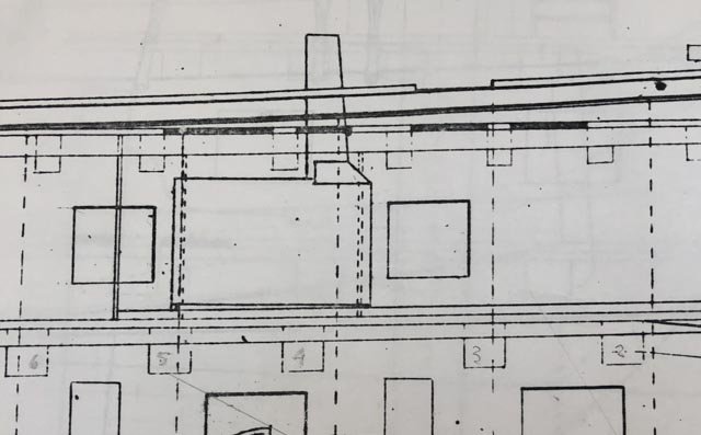
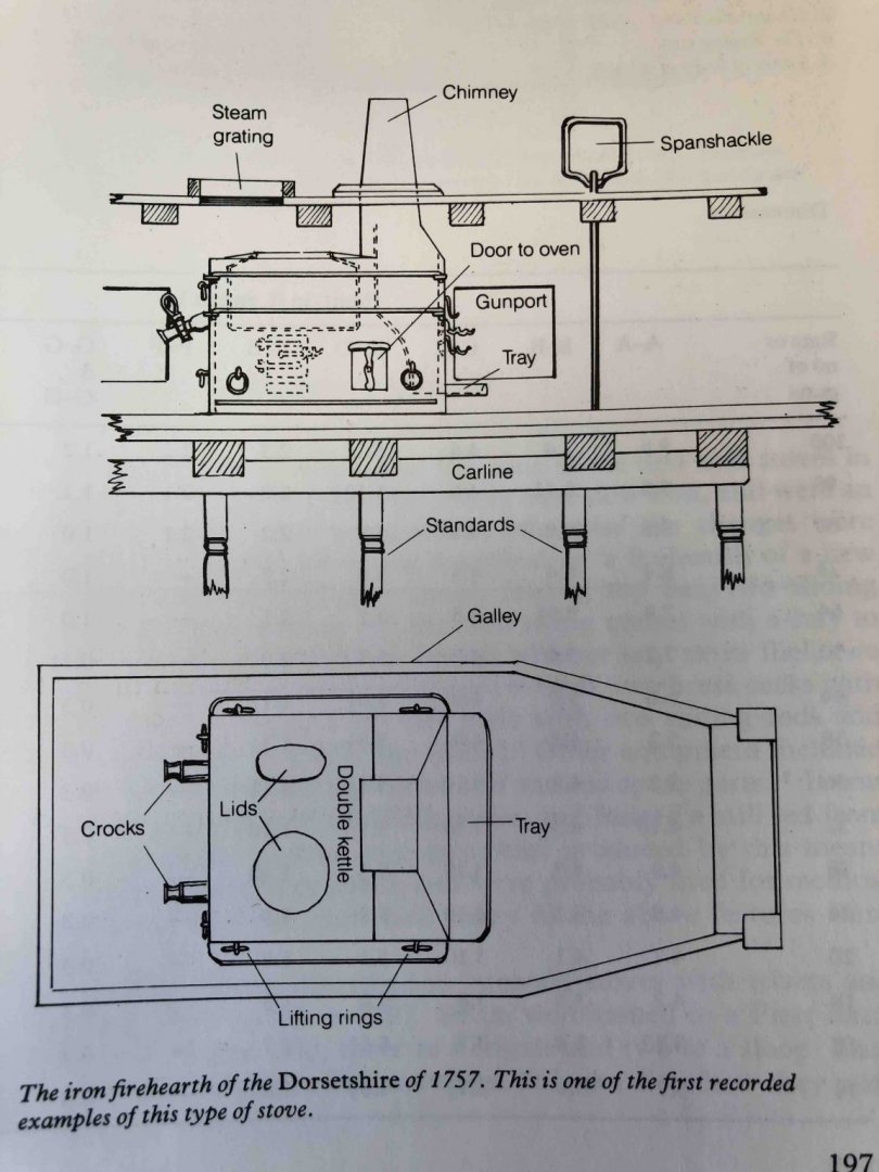
I am working on the gundeck spirketting, but nothing of interest to show yet. While waiting for pieces to steam and dry, I have gone back to working on the drawings some more. I got to the stove, and have some questions. As I understand various sources, the Brodie stove which has been well documented by David Antscherl's Fully Framed Model vol. II pp.81-85 only came into the Royal Navy in the 1780s, according to Brian Lavery's The Arming and Fitting of English Ships of War, p. 197. Since the Bellona was built in 1760, I need to find the stove the predated the Brodie stove. Lavery shows a re-drawing of the HMS Dorsetshire (1757) stove, seen below. The outline and size of this accords very closely to the more schematic stove shown in my Admiralty drawings of the Bellona, so I am confident that this is what the Bellona stove looked like. What I don't understand is what is beneath the stove here. The later Brodie stove had a large metal plate at its base just a little larger than the stove itself, which seemed to sit down on wooden battens adjusting for the roundup of the beam and the sheer of the deck. But both the Bellona and Dorsetshire drawings show a large platform about 4" thick on top of the deck beams and extending to the edges of what I assume are the bulkheads surrounding the galley. Would this have been a brick floor? And would the stove have somehow bolted down through the brick into the beams and large carling below? The cooking equipment immediately pre-dating these early iron stoves was a much larger brick structure, so a brick floor might indeed have been a transitional idea to the new equipment. If this is indeed a brick floor, then the Brodie stove removal of this would have been a vast improvement! Best wishes, Mark
-
Miniature Russian carving tools
SJSoane replied to druxey's topic in Modeling tools and Workshop Equipment
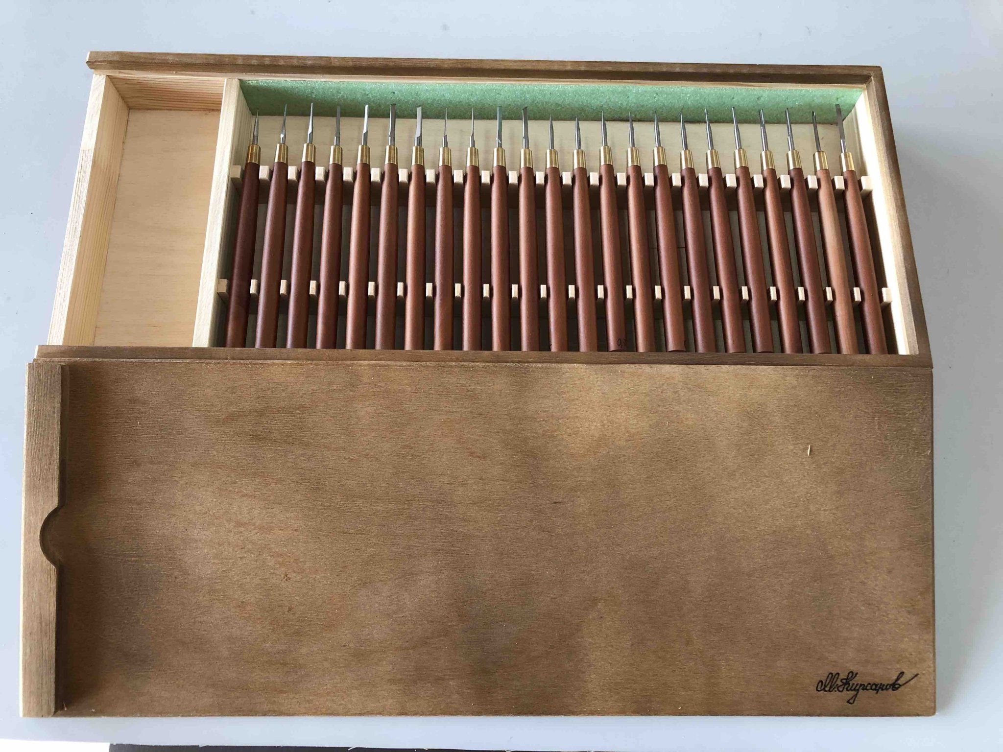
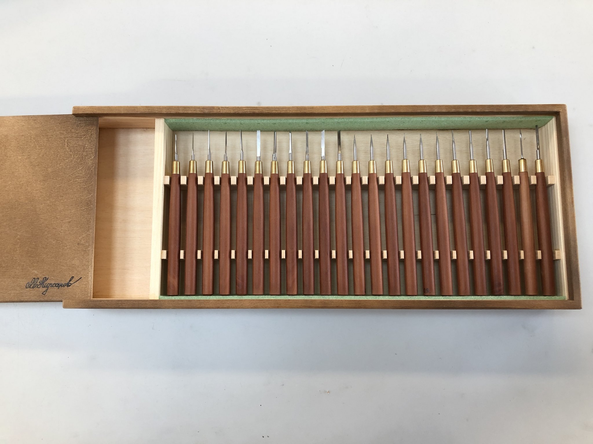
I just received my set, with pear handles. It took 23 days from the time he shipped them, not bad during a global pandemic. They were slow to clear customs in Moscow and cross the Atlantic, but once they hit New York they moved very quickly out West to me. They are as good as everyone has said. Beautiful craftsmanship, super sharp. He even constructed a left-hand storage box for me, because I am left-handed. It means the slot for the sharpening sanding block (not included) is on the left end. Very thoughtful! Mark
- 73 replies
-
- 11
-

-
Siggi, I realized that I have been missing your posts since they are now in a different date category than mine. I wondered why I was not seeing your work! So, catching up, it is looking great! The carving is spectacular, an inspiration for us all. Best wishes, Mark
-
Hi Siggi, I agree, three strakes would not work with Anchor Stock or Top and Butt. And since the wale is the main fore and aft structure resisting tension along its length, it would probably not be simple planks butted together. So that leaves Butt and Hook. And since the Bellona built just 12 years later than the Tiger has Butt and Hook main wales, I would assume that this probably evolved from earlier practices. So not knowing anything else, I would assume this would be the method used by the Tiger. But this is just a guess! Mark
-
HI Greg, druxey and Allan, I'll PM you with what I got. Mark
-
Thanks, Gary, Dave and druxey for thoughts on the hawse holes. I will definitely drill undersized and fill to the correct diameter. Druxey, I was many years into this build before I realized that the hawse hole were related to the location of the hawse timbers! I had faithfully followed the stylized construction methods of the original dockyard models, which used symmetrical hollowed shells at the bows, bearing no relationship whatsoever to the actual framing construction. For a long time I pondered how big, and in what location, they would be drilled, trying to eyeball dimensions in photos relative to other things whose sizes I knew. Finally, after reading about this in David Antscherl's Fully Framed Model series, I was able to construct in a drawing where the hawse timbers would have been had I constructed this accurately, and therefore where the hawse holes would be drilled. Indeed, in the next model..... On another topic, I just received the micro chisels I ordered from Mihail Kirsanov in Russia. A number of Model Ship World builders recommended these, and they are indeed the premier micro chisels of all time. Exquisite craftsmanship, sharp as anything, and all of the shapes needed for ship ornamentation. I highly recommend them. They took more than 3 weeks in the mail, surviving the uncertainties of mail delivery during the pandemic. Now I just have to do them justice and carve something at least as beautiful as the chisels themselves. Sharpening these will definitely be a challenge, there are some so small it is hard to see the surface needing sharpening! Mihail sent sharpening instructions which I will try to follow to the letter. Google Translate is our friend here! Best wishes, Mark


-
Thanks, Gaetan, and I am also thinking about how to build a little jig to ensure that I drill the pilot hole at exactly the right angle. Getting this wrong will put the hole in the wrong location inboard. Or, do you straighten the hole up when you finish shape it with files? Mark