HOLIDAY DONATION DRIVE - SUPPORT MSW - DO YOUR PART TO KEEP THIS GREAT FORUM GOING!
×


SJSoane
-
Posts
1,649 -
Joined
-
Last visited
Content Type
Profiles
Forums
Gallery
Events
Everything posted by SJSoane
-
 Hi druxey, Thanks for the idea, I was able to move the rails outboard by about 4 inches, by reducing the outboard curvature of the aft-most head timber. This helped with spacing looking more like the Bellona model in a number of areas. But there is a limit to how far this outboard curvature can be flattened out before it no longer looks like the Bellona model. And changing the curve moves the middle and lower rails in a set relationship to each other, since their outboard faces align with the outer curve of the head timber. So I can't get that much greater clearance between them. This results in the following rail locations. The location of the seats athwartship is based on my reading of Mark P.'s latest photo, which shows the fore-most outboard corner of each seat sitting on top of, but not projecting beyond, the outer face of the middle rail. And as I read the photo, the fore-most seat does indeed discharge onto the top of the lower rail, by about its thickness. I think through a great team effort here, I have located these as well as I can until I start building and get another perspective entirely! Mark
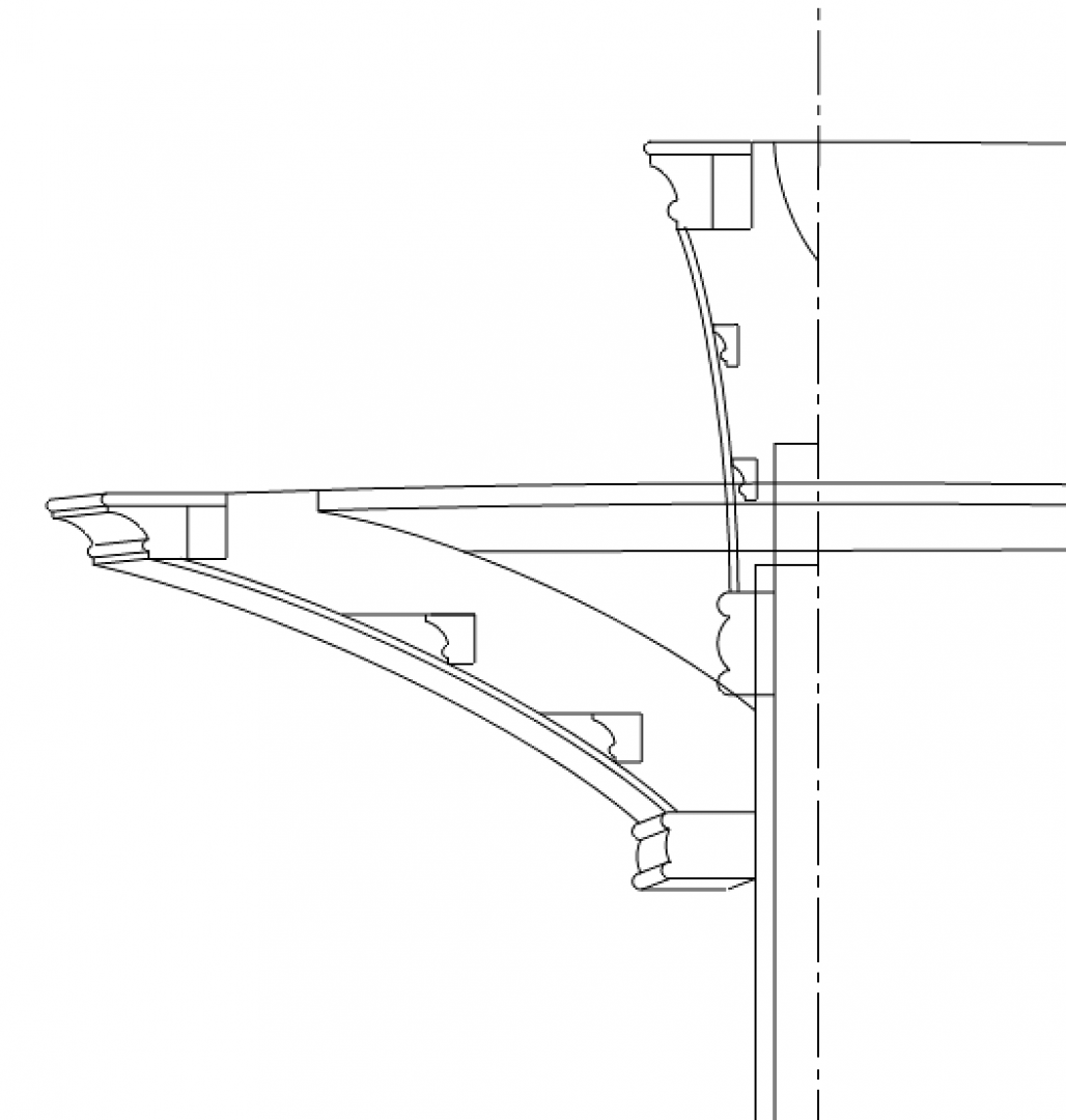

-
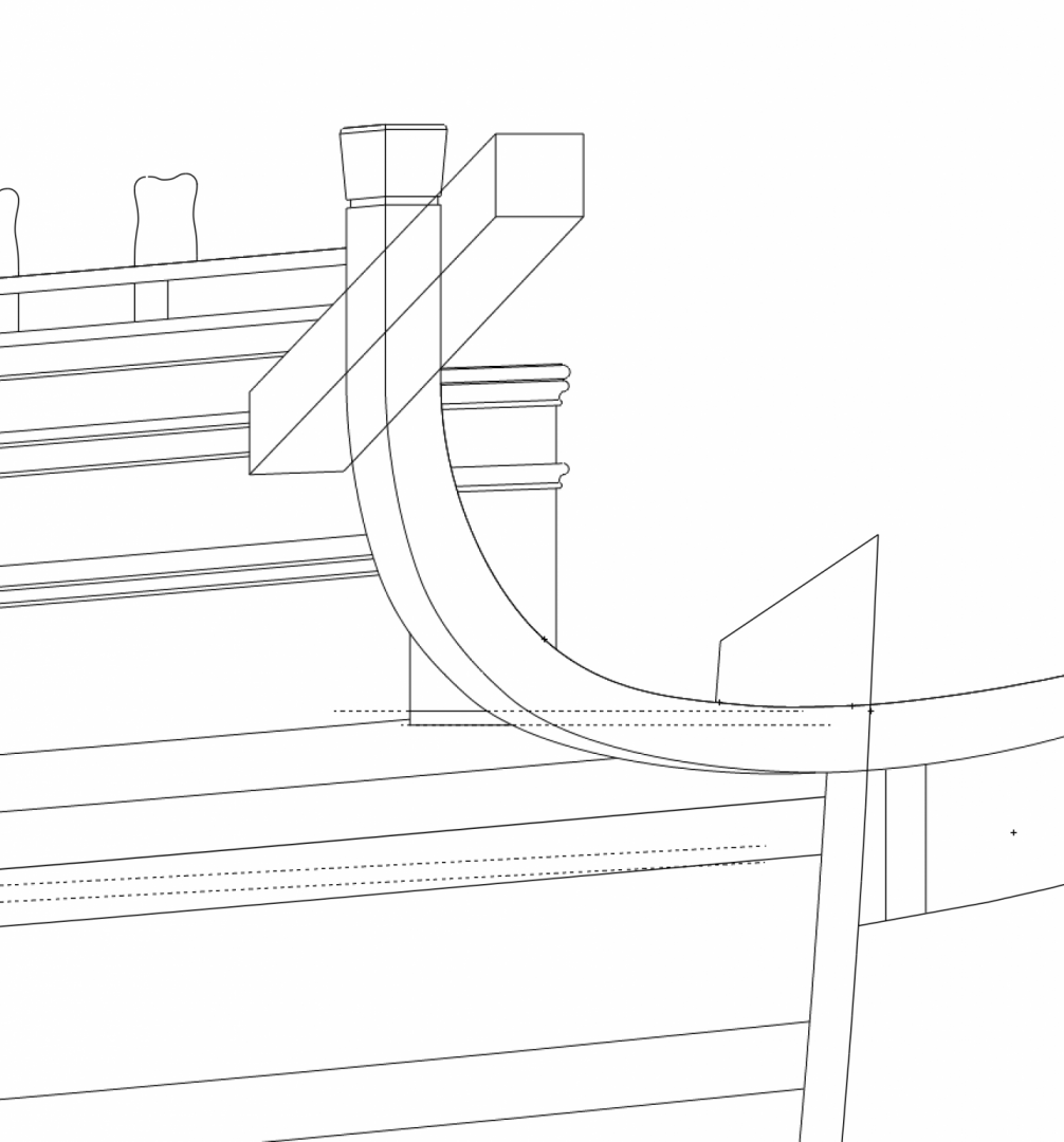
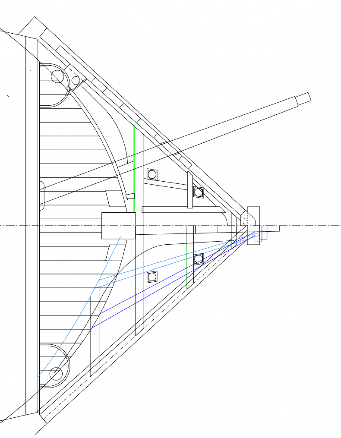
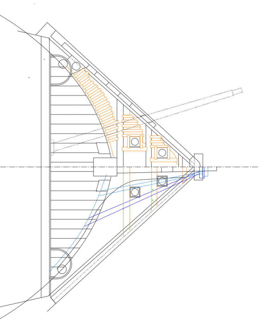
thanks, Mark, this are so useful! I was inspired to redraw the middle and lower rails, to find out if I had something wrong. I did indeed. I ended up drafting very accurately the first and third head timbers, and where the lower and middle rails would be cut into them in section: I then plotted the distance of these rails from the center line in the plan, and extended the lines aft to intersect the hull and forward to intersect the main rail as it sweeps up. I discovered that the aft ends moved more inboard than I had drawn before. So now, knowing these are in the correct location, how would the seats of ease fit? Looking at Mark's photos, the one thing that seems inarguable is that the foremost, outboard corner of each seat of ease sits on top of the middle rail, looking to me like it is just flush with the outboard face of the rail. This means it would have to be cut away for the thickness of the middle rail. It could maybe be a little more inboard, but looking at the foremost seat, it cannot move much more inboard without encroaching on the gammoning which is directly behind it. So I think these are the right location athwartships. There just does not seem to be any way that the fore seat avoids fouling the lower rail for the inboard half. Maybe there was a sloped bottom to the seat, directing things away from the rail? Mark
-
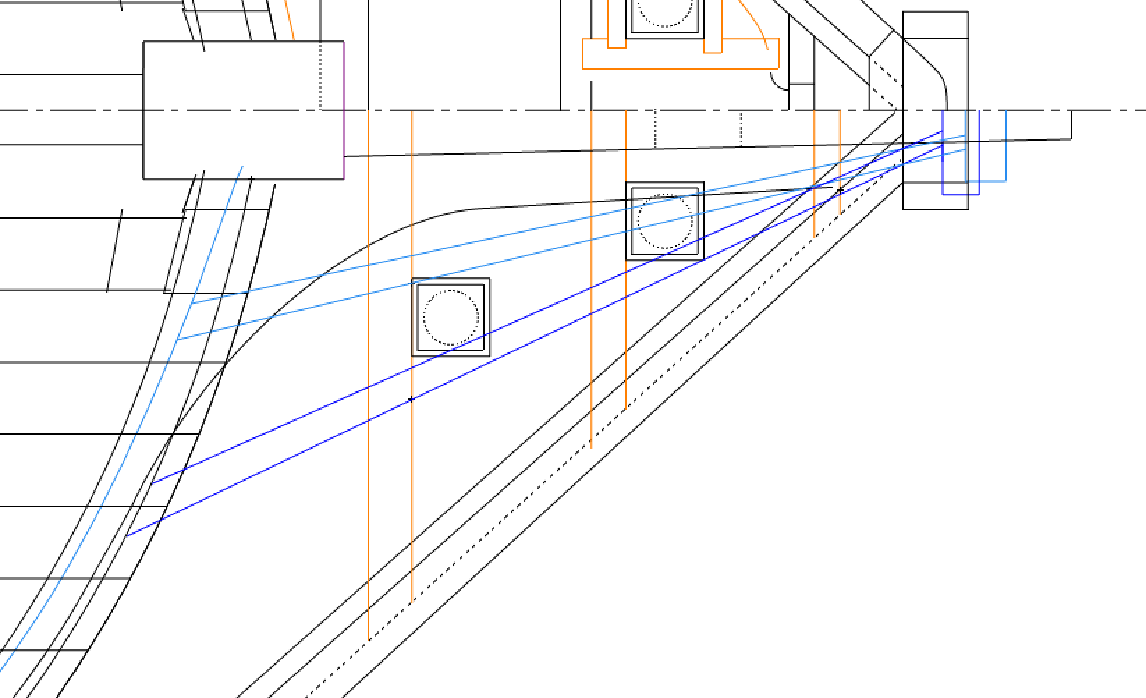
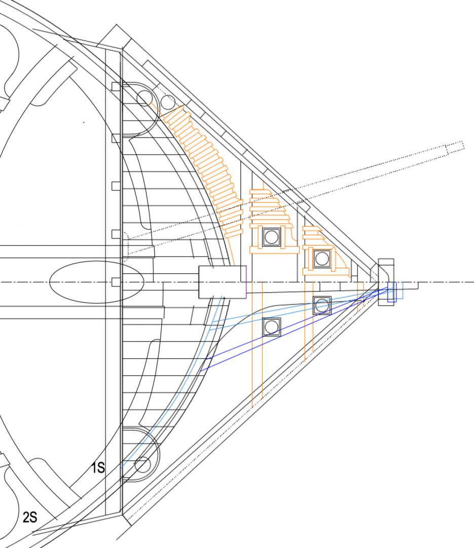
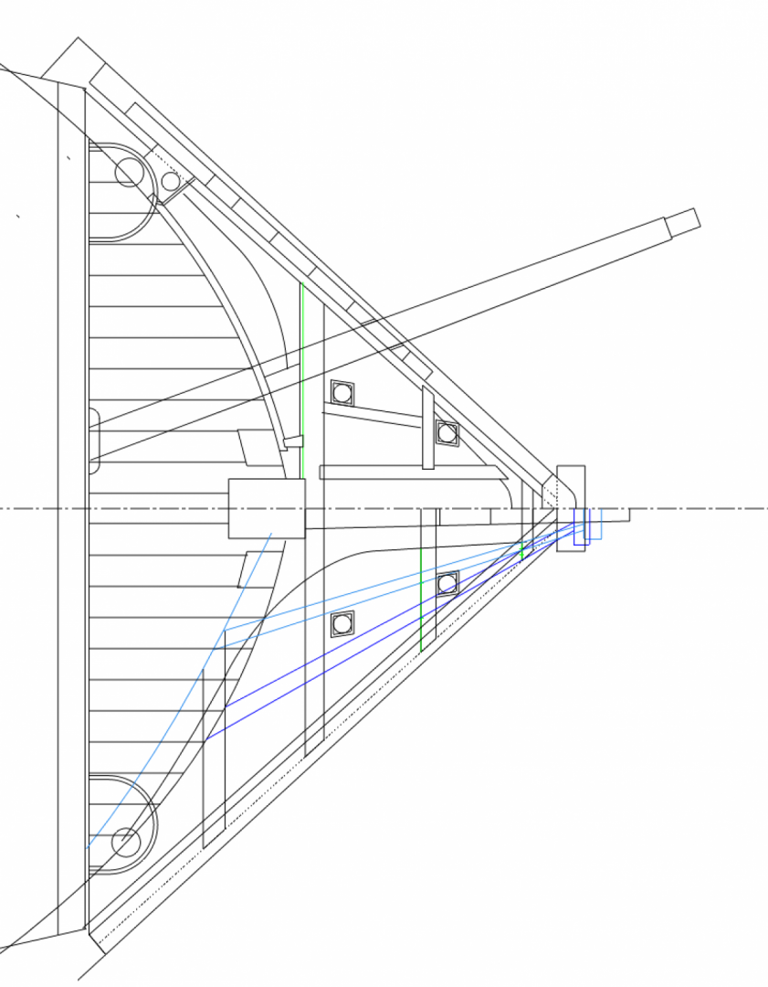
Thanks again, Mark P, these photos were invaluable. I saw a number of things I did not understand before. For example, the head timbers underneath the main rail are fore of the beams on the grated deck. I had assumed they were aligned. I could not make spacing work out until I realized this. I remember spending a long time many years ago at the National Maritime Museum in Greenwich making notes on this model. I assume it is now put in storage, or is it on display at Chatham now? It is now painfully clear that the foremost seats of ease discharge directly onto the lower rail, as we can see in the lower half of the plan (light blue is the lower rail). There simply is no way around this, because the discharge tube could not cut in the inward face of the middle rail (darker blue). And it could not move inboard at all, because it would get in the way of the gammoning for the bowsprit. As druxey points out, this is probably washed well while at sea, but in port it would be messy indeed. I imagine some poor shlub was assigned latrine duty to clean off the lower rail every few hours... And here is a drawing working out the shape of the aft most head timber, in order to locate the middle and lower rails. Fascinating, complex geometry! Best wishes, Mark
-
Mark, Thank you, thank you! This is invaluable. So much guesswork without this. I see there are a few places to fall through on a dark night... Best, Mark
-
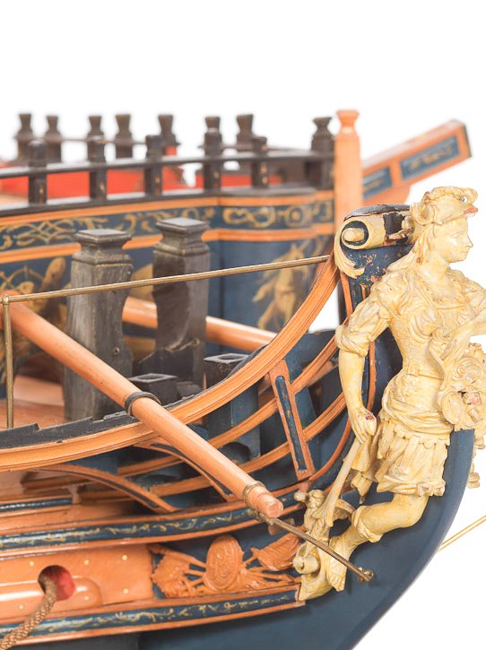
Hi druxey, I thought for a long time that these two seats of ease were on opposite sides of the center line, therefore just two forward of the knight heads. But after boosting the exposure in this photo and looking more carefully at the chutes below, they seem to be both on the starboard side, hard up against the second and third head timber respectively, and discharging between the middle and lower rail. The foremost one is definitely on a steep incline, and really exposed; it could not be the first choice if others were free! There is also very little clearance between the two rails in plan for the chute of the foremost seat, making this a messy detail if I read it right. My plan as currently drawn does not seem to align the sides of the chute as nicely with the lower rail as we see in this picture; maybe my parallelograms need to get a little more acute for this to work right. If they do indeed lie flat both on the head timber and the rail, then that is a sturdy means of fastening these in place, rather than just hanging free below the grating. I also notice a large disparity in the size of the hole for the warrant officers in the roundhouses, and the size of the hole in the seats of ease for the less fortunate sailors. I don't know what conclusion to draw about this... I welcome further thoughts on how this is all fitting together! Mark
-
Thanks, druxey, Steven, and Gary for your kind comments. And Gaetan, that is fascinating to see the two ships overlaid to see the differences. I had understood that the Bellona was largely copied from a captured French ship, but it must have been the hull lines and not the details. The French ship does look more elongated, whereas the Bellona like many English ships has an abrupt sweep up, even back, just behind the figurehead. This is a good example of elegant French taste! I have spent the day figuring out more of the head, now looking at the plan. I had no idea how little I had worked things out until I drew this. Keeping the gammoning between two head rails, making sure the seats of ease did not discharge onto the middle and lower rails, keeping the seats of ease away from the bumpkin, on and on it goes. There sure are a lot of things to figure out, and good to draw it before making mistakes in wood. I discovered today that 15 years ago when I cut a slot in the gammoning piece when making the keel and stem assembly, I put it in the wrong place. One of the head timbers is right in the way, so the bowsprit gammoning could not be installed as I have built it so far. Thankfully, the trailboard will cover the mistake. Don't tell anyone! Mark Mark

-
Here is one more variation, with the shield to the left side. It will have to await the construction of a maquette to visualize exactly how this goes. For an image of Bellona and shield location in a 1906 sculpture by Bertram Mackennal, see: https://commons.wikimedia.org/wiki/File:Mackennal_-_War.jpg I understand this is on the grounds of the Australian War Memorial in Canberra. Mark
-
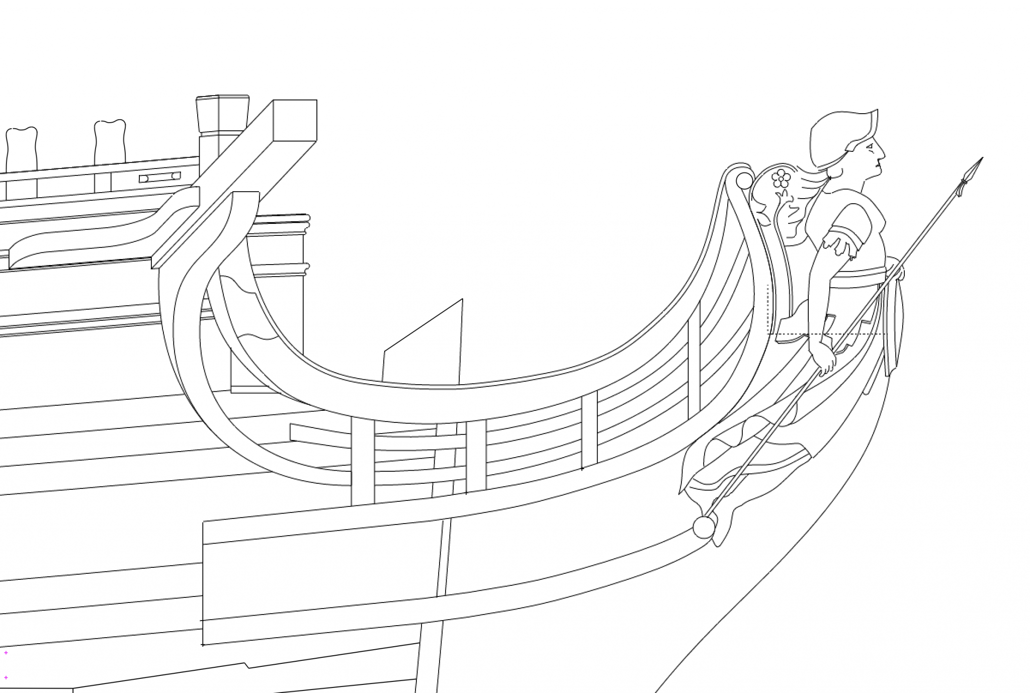
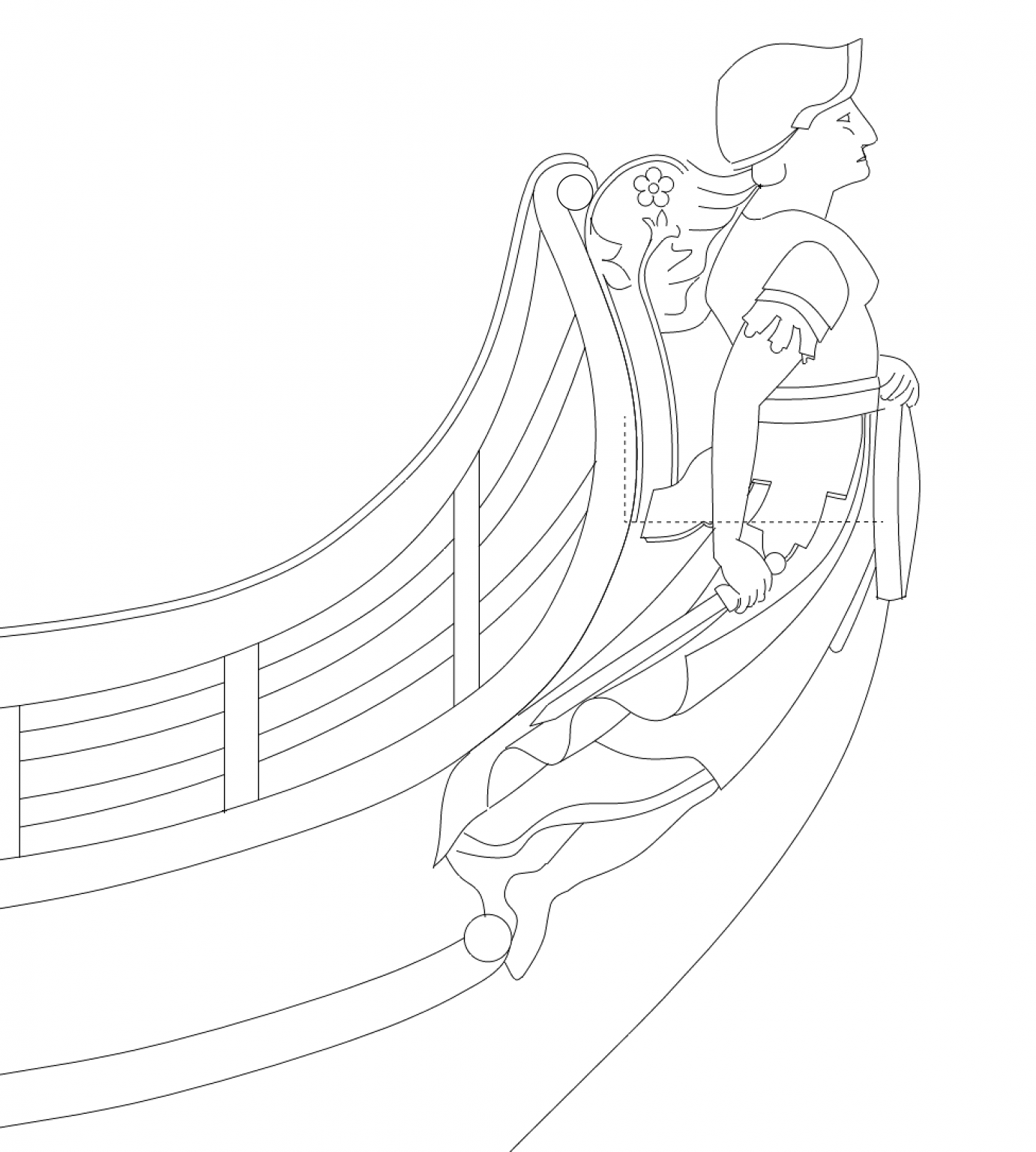
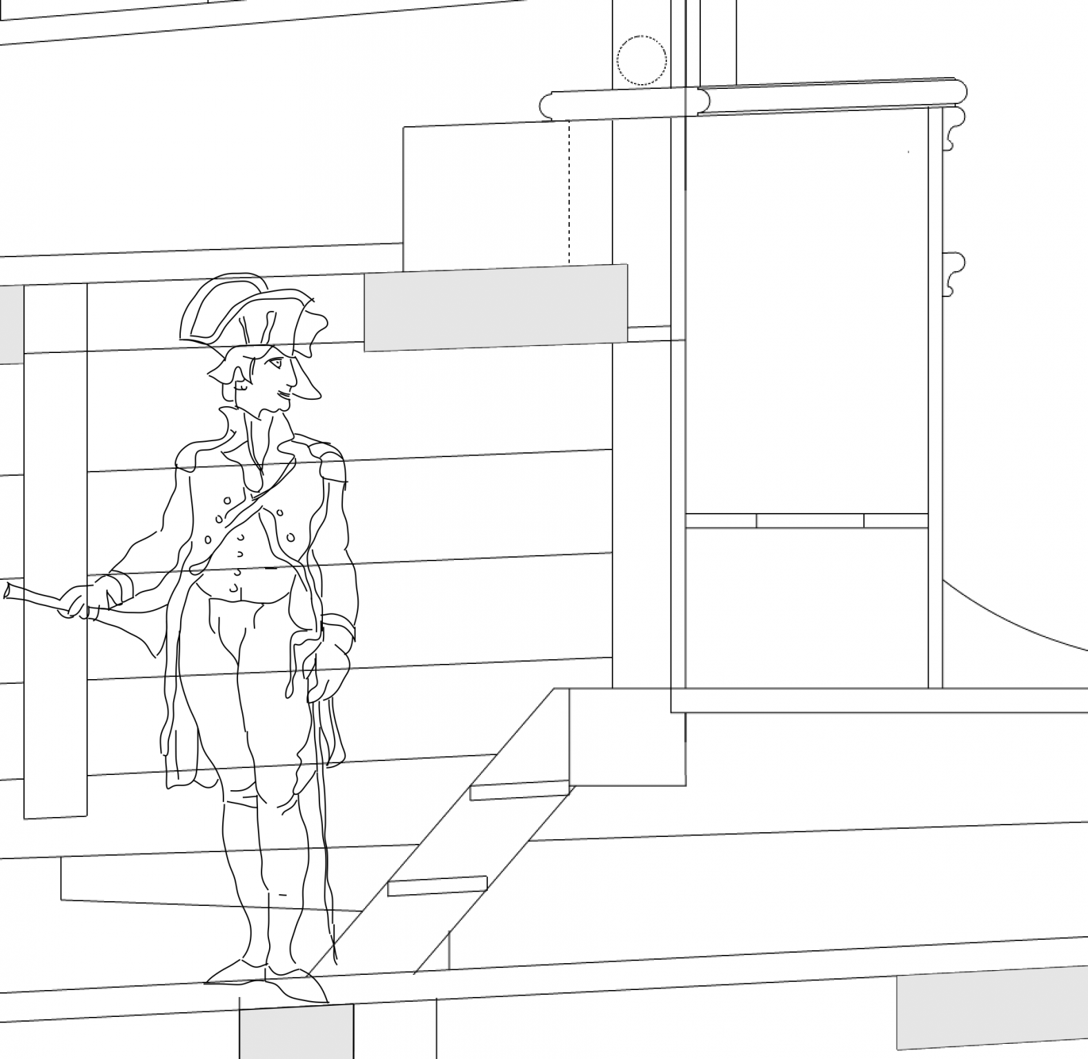
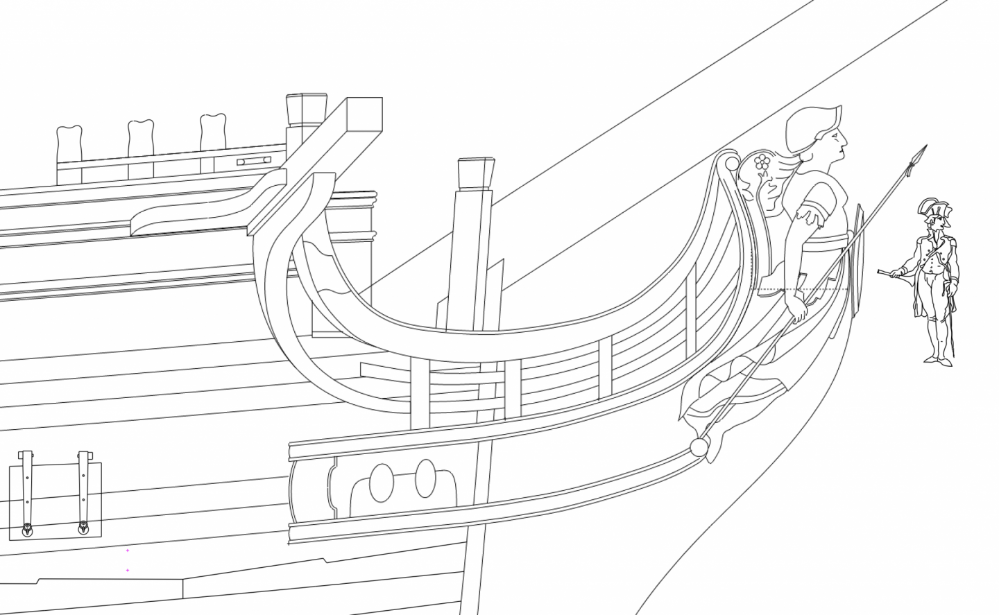
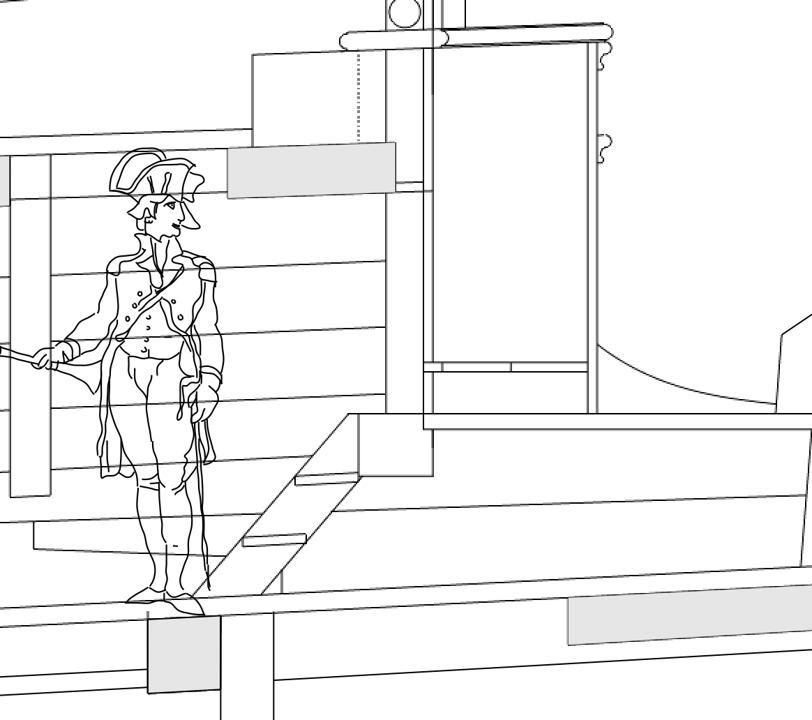
Hi druxey and Mark, I like the idea of her holding the shield; one less hand to carve! Here is an updated version, minus the gorgon that I don't feel like drawing right now... I put the captain next to the figurehead just to see how big this really is. She is one big lady! I remember seeing original figureheads in various maritime museums over the years; now I fully appreciate why they were so big. Mark
-
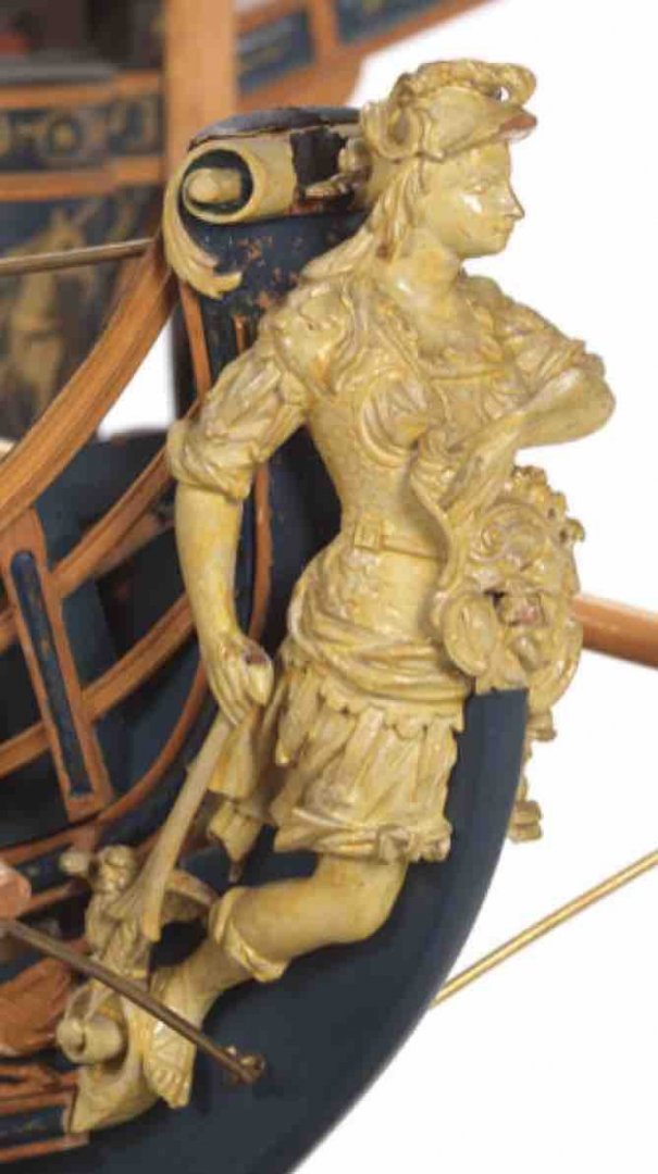
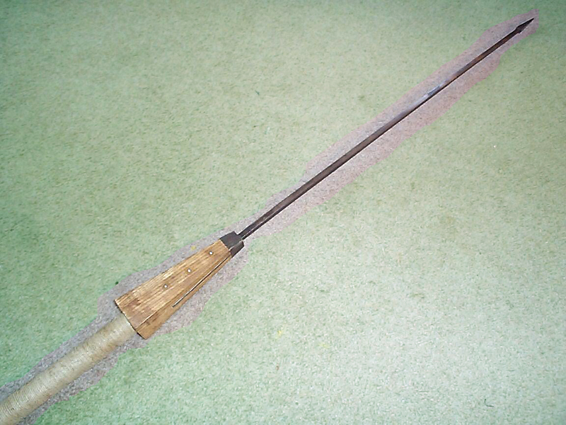
Hi Mark, Yes, it is confusing, the Roman spear/javelin. As I read more online, there appear to be one version, the pilum, which has a long metal shaft put into a shorter handle like what the second Bellona model seems to show. But there also appears to be another version of a javelin with a metal head only a foot long, connected to a 2 meter wooden shaft. That is what appears to be held by the Bellona sculpture in posting #721 above. Lacking any further evidence, I will go with the javelin like the sculpture, treating it as a wooden shaft with a one foot long metal head. So I will have to paint the metal shaft as wood in my model. While I was at it, I finally nailed down the size the hawse holes. Since I did not do my framing as actually constructed, I had no idea where the hawse pieces were located at the head, and therefore where the hawse holes were located (since they are drilled with half out of each adjacent hawse piece). So I constructed their locations here. And I did this while waiting for glue to dry in more planking. Mark
-
Thanks, Jason, that makes sense. I just didn't think the sword was prominent enough, so I followed Siggi's good advice about a removable metal shaft and went back to the lance or spear that we see in the first image in posting #1721 above. Here is what it looks like. I could make the spear out of blackened copper, and drill a hole in her hand to hold it. Or, would it be shiny metal in real life? Now I really, really, am getting back to planking today! Mark
-
Hi Mark P., I forgot to comment on your posting. Yes, it was interesting to see the bird in the sculpture and the figurehead. I wonder if the figurehead sculptor saw the stone sculpture for inspiration, or whether it is indeed a reference to a well known view of the ancient Romans regarding predicting the future. I haven't come across anything about this yet. And also, interesting about "bella" as referring both to aggression and beauty. Does anyone more literate in Latin than I am know why the root is common for what one would assume are almost diametrical opposite ideas? Mark
-
Siggi, that is a good point about the spear being removable. I may look again at the spear idea instead of the sword. The sword doesn't look very impressive so far.... And Greg, thanks for the kind comment. I have never carved anything this small, so this will be a big uphill challenge. I had been looking forward to a future workshop with you and David on carving, but in light of the pandemic who knows when that will be possible again? My son is starting to acquire expertise on 3-D printing. If I get desperate, I may print it and paint it ochre! And will I ever tell anyone if I do? But that would also require learning Blender, which is no easy task as I see it right now. Might be easier in the long run to carve it from wood.... Best wishes, Mark
-
Greg, the masting looks terrific. Well done! I see you used the Fiebings shoe dye for the black parts. How did you stop it from leeching into the bright work parts of the masts, where the black and the natural were all the same piece of wood? Best wishes, Mark
-
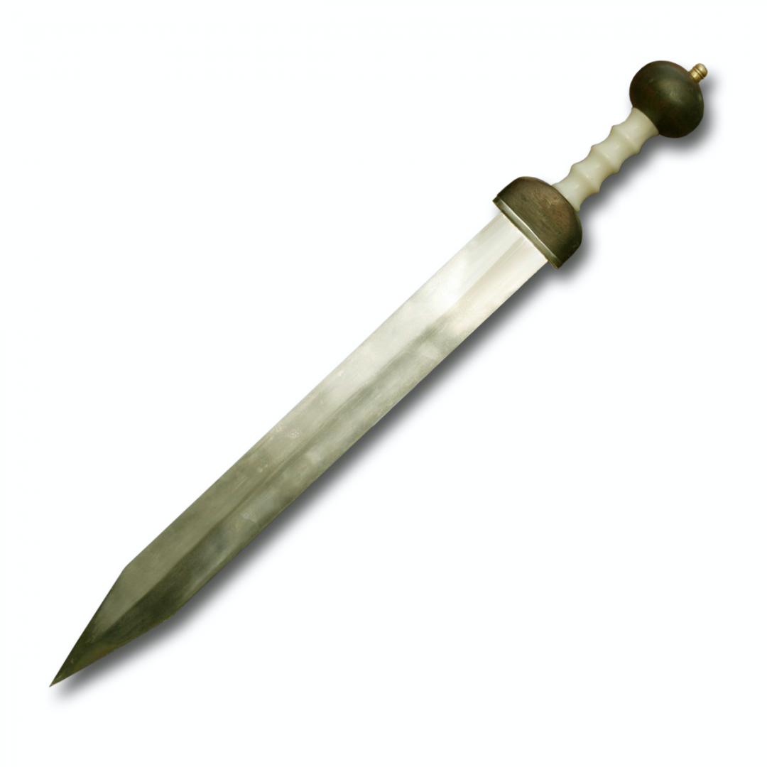
Thanks, Mark, Jason and Mark. Fascinating to learn more about Roman armor and tactics. I played with the spear idea, since Bellona is sometimes depicted with one. But I began to worry about a very thin piece of wood jutting out from the model, and thought that mine would meet the same fate as that carried on the second Bellona model--it would be broken off eventually. So, I tried the sword idea, at first the shorter Gladius and then the longer Spatha. I am showing the Spatha in this drawing, just because it looks a little more scary in Bellona's right hand.... The shield cannot be made as large as those shown in the images in my previous post, because it would cover most of the figurehead. So I have scaled one down to what looks like a shield in the second Bellona model, with her resting her left hand upon it. I confess I was tempted to place the sword in her left hand, since I am left handed. But then decided I should stick with greater authenticity. But who is to say that Bellona was not left-handed? It would have made her more "sinistra"😙 Mark

-
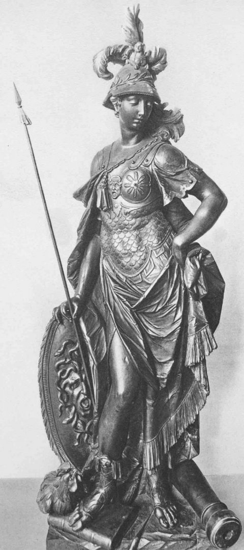
Thank you, Marc, druxey, Mark and Mark. You helped reinforce an already happy marriage, and my wife feels vindicated! So this conversation led me to learning more about the goddess Bellona. There is good coverage in Wikipedia: https://en.wikipedia.org/wiki/Bellona_(goddess). I discovered that she had a temple devoted to her in Rome, and that she was celebrated every June 3. I will have to observe that date from now on... Interesting that she was noted for wearing a plumed helmet, which is in the second model but not the first. In various artistic images over the ages, she is variously entirely covered in armor, nude, and everything in between. She mostly carries a shield, often covered with a gorgon (see in sculpture below), the mythical creature with snakes for hair. Weapons are harder to generalize. The 1770 sculpture below by Jean Batiste Straub shows a thin spear, with perhaps some feathers or metal ornament underneath the head. Johann Baptist Straub, 1770 Public Domain http://warburg.sas.ac.uk/vpc/VPC_search/pdf_frame.php?image=00034081 And is this what we see in the second model of the Bellona, maybe made a decade after the Straub sculpture, with a spear held upside down? It looks to me like there was once a longer shaft, broken off at her hand. Otherwise, I don't know what that weapon is. But why does the shaft appear to flair out like a handle just below her hand? Maybe it is something like this reproduction Roman spear: http://romans.etrusia.co.uk/roman_army_intro_p3.php I did not find any art examples with a sword, which I assume would be like the reproduction below. I am not sure of how this would be held, for upward or downward thrust. https://commons.wikimedia.org/wiki/File:Uncrossed_gladius.jpg I really should get back to planking.... Mark
-
It is looking great, Marc. Masts give a hull an entirely new perspective on just how big these ships were! Mark
- 2,696 replies
-
- 4
-

-
- heller
- soleil royal
- (and 9 more)
-
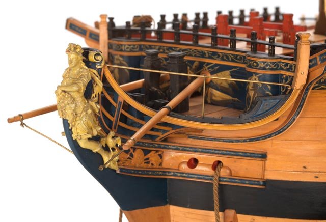
The cannon carriages lined up like that really shows the true function of these great ships. Imagine the noise on that deck when a broadside was fired! It is looking great, Siggi. Mark
-
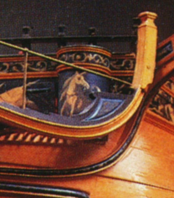
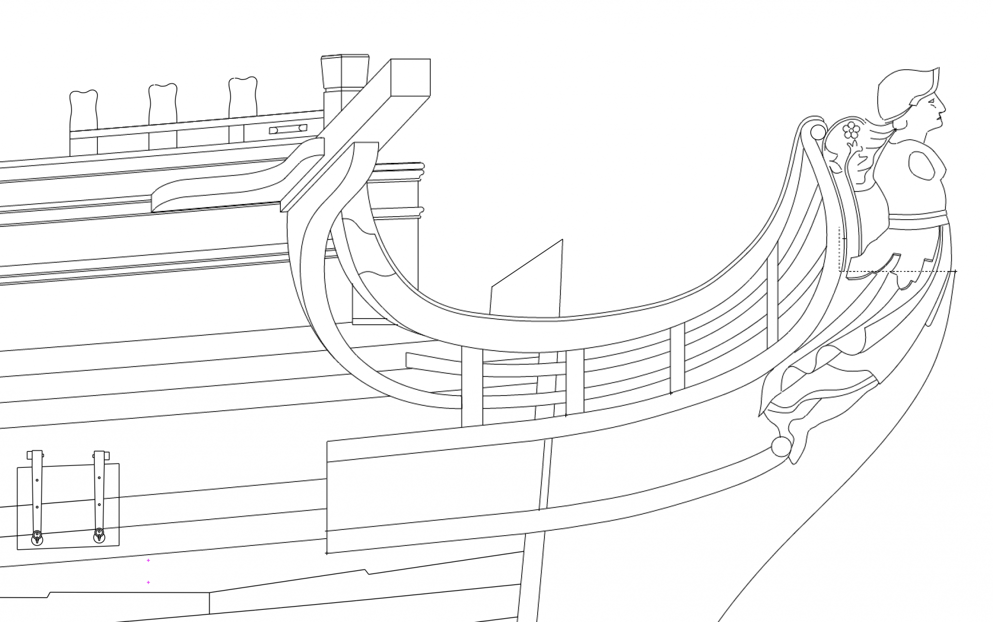
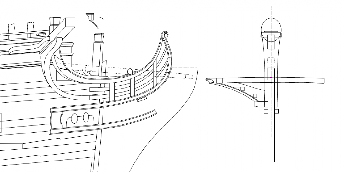
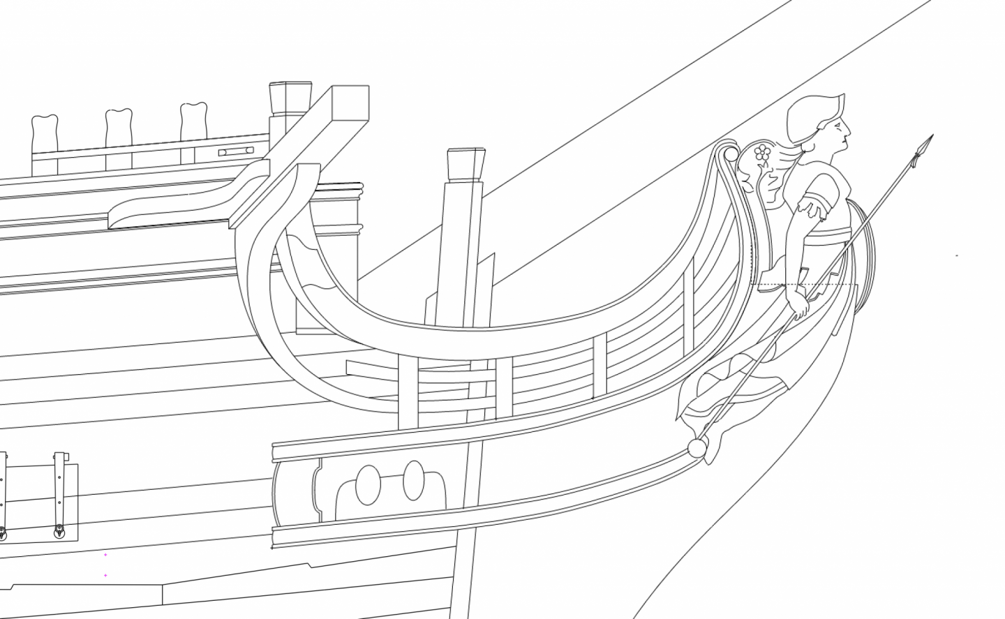
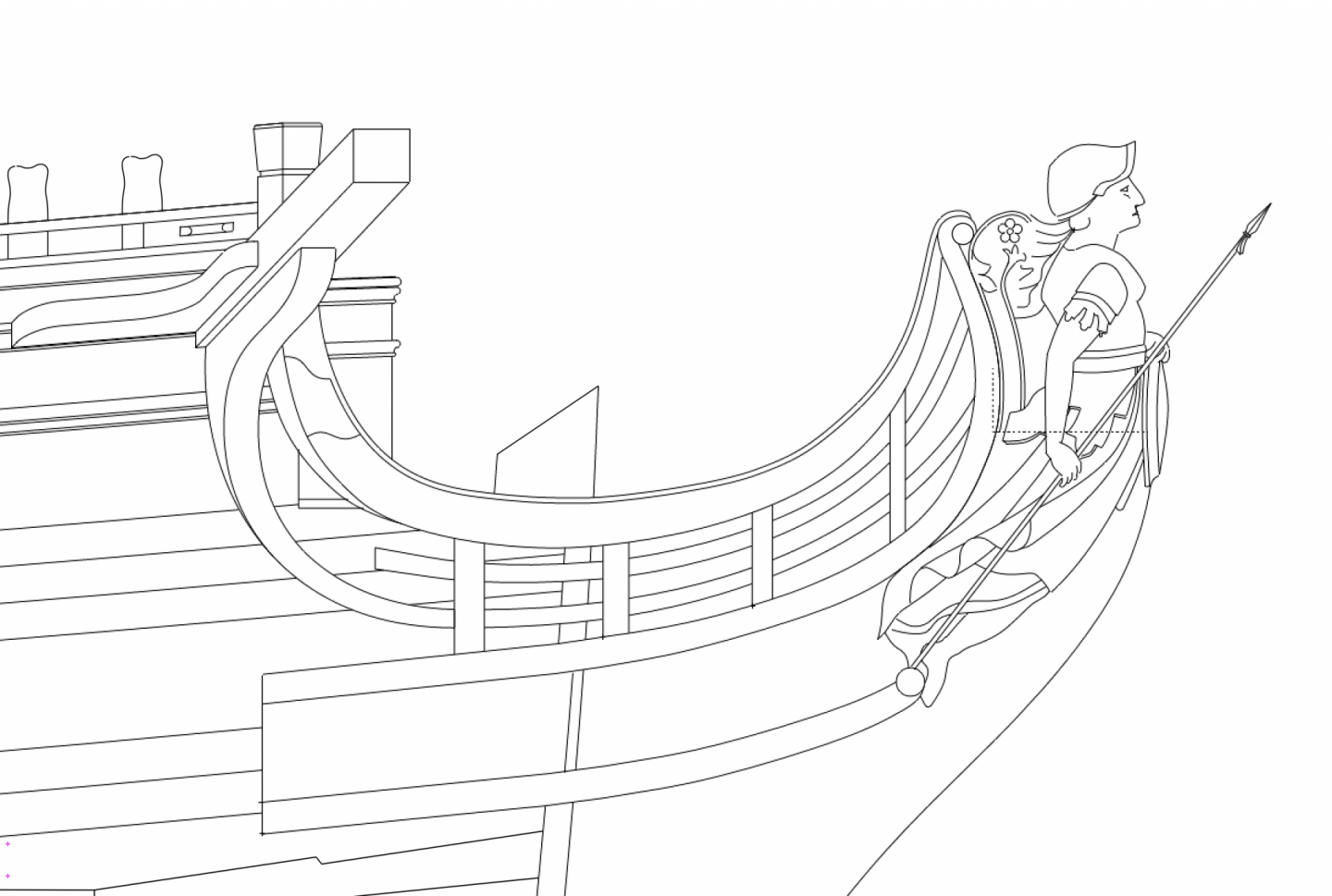
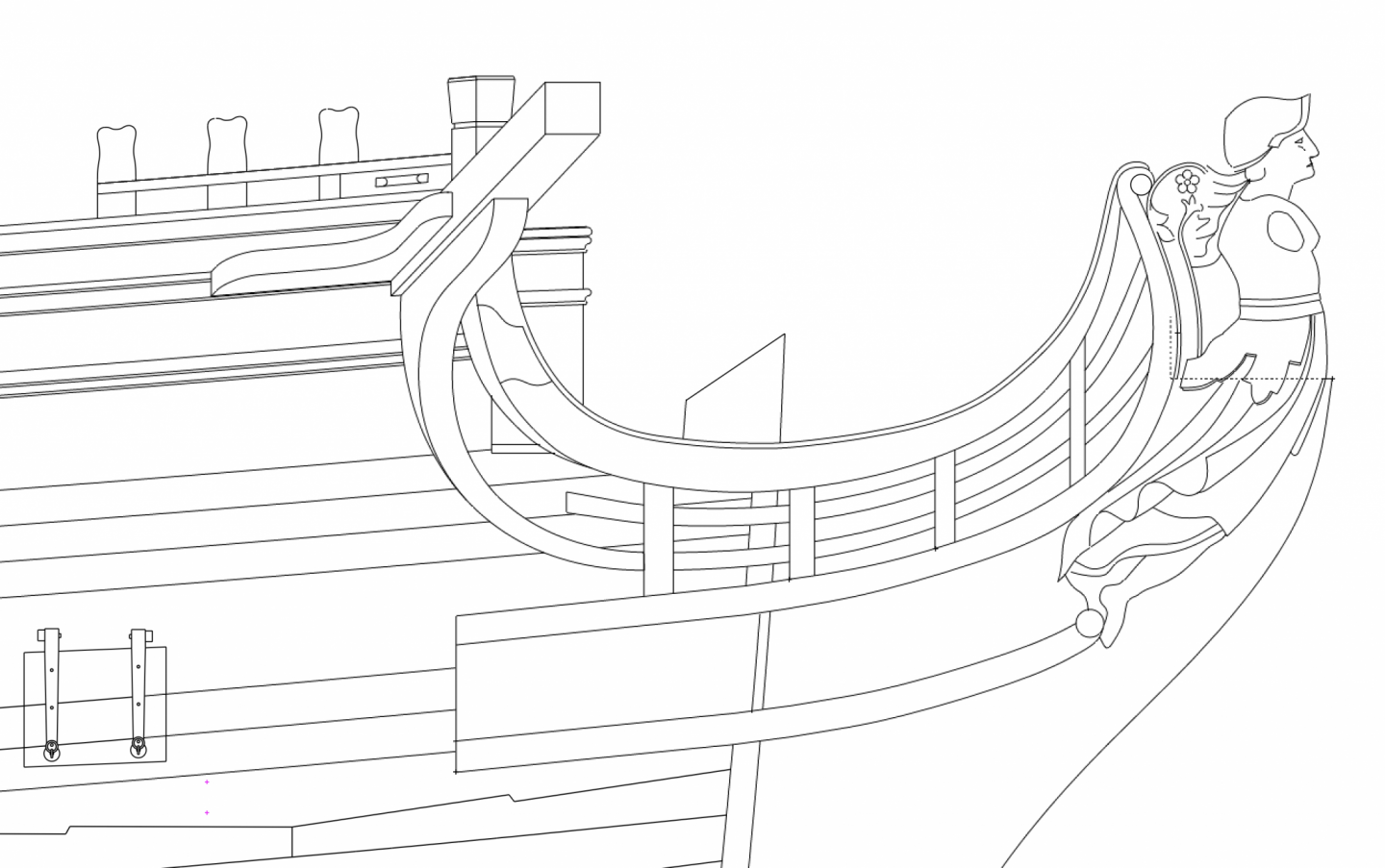
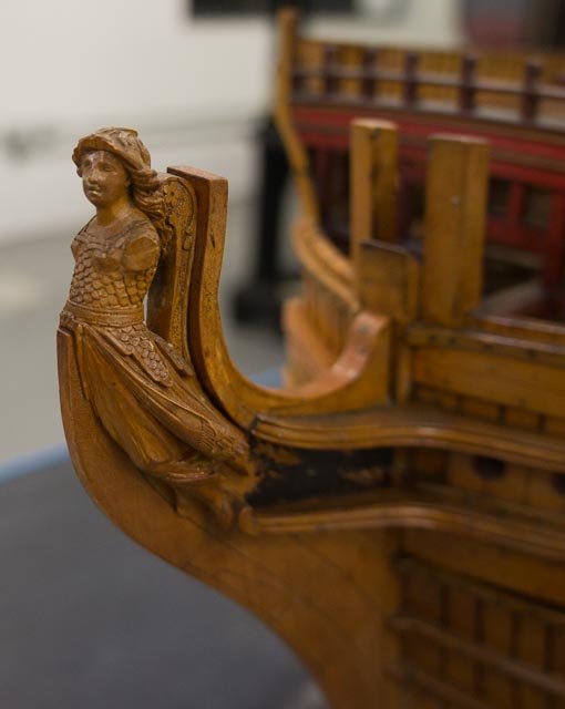
Well, it was a rainy day, and I felt like drawing more than building. I kept going on the head, including the figurehead. The curve of the various rails needs refining, but I thought I would do that after after expanding these to true length. This at least gives me approximate locations of things. I have to make a decision now about which figurehead to use. The one I prefer and have drawn above is the one on the original model, likely built about the same time as the ship was constructed ca. 1760: The other is on the second model, either constructed or modified when the ship itself underwent a major refit around 1780: I like the simplicity of the first one; too many gee-gaws on the second one, like the bird on Bellona's heel. And I have made many decisions about details over the years consistent with the original design, not the second model. So I really need and want to stay with the look of the first model. However, my wife is insisting that Bellona needs arms if I build the first version. Is it at all possible that the original figurehead would be without arms? Does anyone know of other figureheads of this time without arms? If not, I could assume that the figurehead was shown as incomplete and in process, just like the rest of the model itself. In that case, I could reconstruct arms, following the quarter post sculptures on the stern:
-
Thanks so much, Mark. It is difficult to find information for ships designed around the Bellona's 1759 date. Most published sources I can find are from several decades later. I have to assume in many cases that things did not change all that much. So I look forward to comparing these numbers to the Ship-Builder's Repository and to Steel, to see the differences if any. I do note in what you sent that it does not seem to prescribe the length of the Cat Heads outboard, only the length inboard, when it is called a Cat Tail, is it not? Do I read this correctly? Mark
-
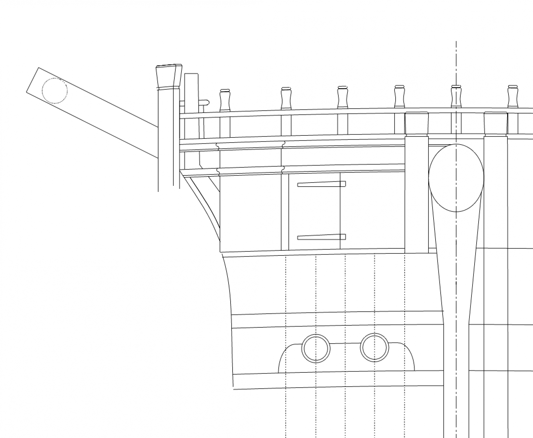
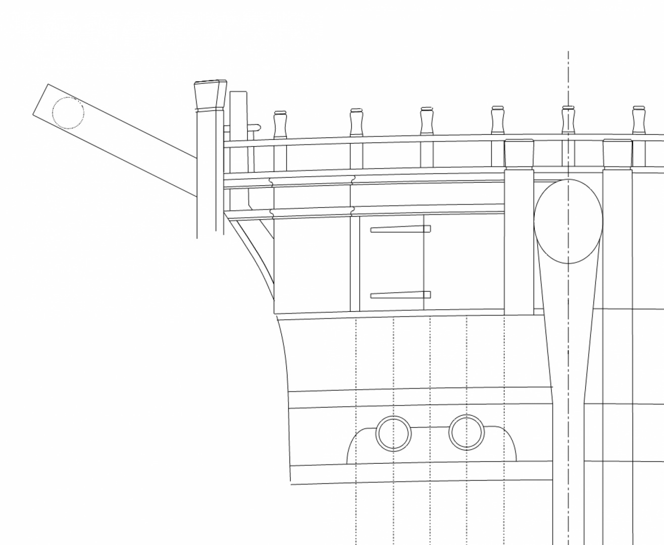
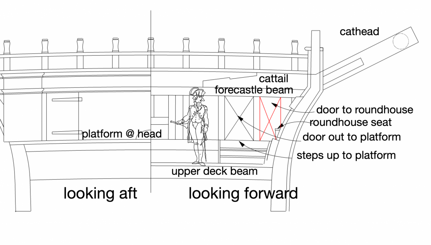
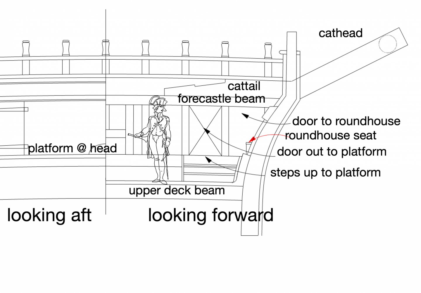
Thanks, Mark, that is a terrific book! The 74 gun ship definitely shows its reduction in size in everything relative to the larger Princess Royal. The Bellona hull at this point flairs out dramatically, to provide sufficient overhang for the catheads and anchors. It leaves less space at the bulkhead for the roundhouse, if the roundhouse is pushed outboard far enough beyond the hull to provide the discharge for the head. The red lines below show a 1'-8" wide door, the same as the doors in the quarter galleries aft. It still needs to chamfer off the lower outboard corner because of the flair of the hull. But it looks like it would work with hinges on the vertical inboard post. Thanks! Mark
-
Further evidence that the roundhouse has to be at the level of the platform; the side slopes in so far that access to it would disappear at the upper deck level. I am now showing the seat tucked around the corner, as in the last post. But interesting question as to how a door would be hung on the roundhouse. It would have to be hung on the inboard post, and would be a trapezoid (trapezium outside North America?) in shape. And I would think pretty annoying to try to get around it while squeezing into the opening. OK, enough of this, back to planking!
-
Hi druxey and Ron, By jove, I think you two together got it! Pushing the seat off center into the outboard side leaves plenty of room to actually crawl in the roundhouse with room to sit. Just no room for the rack for copies of the London Times.😏 It is a bit of a bend to get in, but not hugely worse than the quarter gallery doors for the officers. They all were just more nimble back then, I guess. And Ron, please do keep posting pictures like that. It was immensely helpful! Mark

-
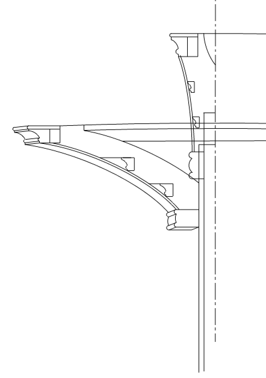
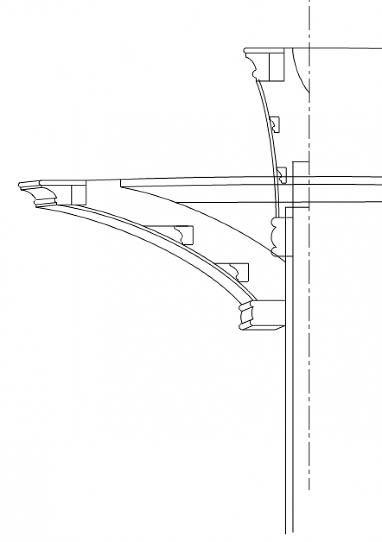
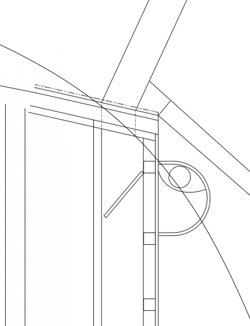
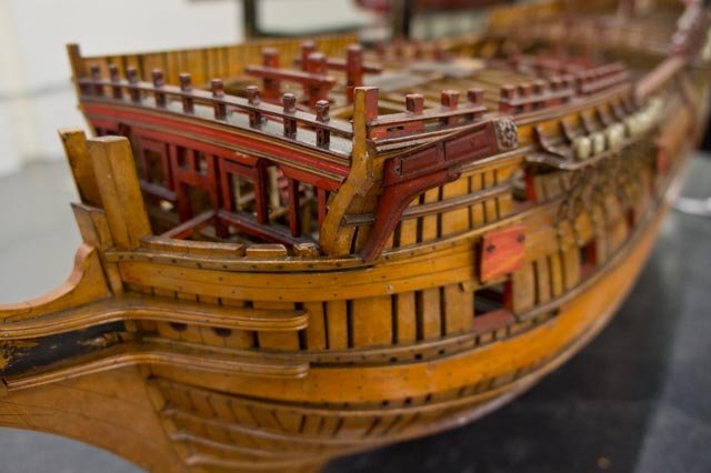
quick update on my last post's last question about access from the upper deck; the access could not be from the upper deck because the beam forming the aft edge of the platform is in the way. We can see the beam in the photo below as the lower red beam, with the doorway to the roundhouse above it just at the extreme port end of the bulkhead. And we can see the beam here in the cross section. This leaves the roundhouse as a very tiny affair!
-
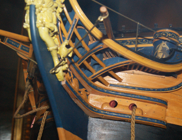
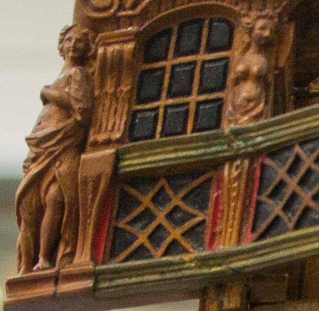
Hi druxey, I thought that for a long time, but on closer inspection of the 2nd Bellona model, it shows the roundhouse base sitting on top of the platform, not the upper deck. In this photo, we can see the ledges or grating that extends out from the level of the platform, and it is the same level as the bottom of the roundhouse that is just peeking out beyond the main rail. in the drawing below, the upper dotted line is the level of the platform and grate, the lower level is the level of the upper deck. or, what if the seat is the part cut off at the level of the platform, but the access from the upper deck is at the level of the deck? It would be a cantilevered seat of sorts... Mark