HOLIDAY DONATION DRIVE - SUPPORT MSW - DO YOUR PART TO KEEP THIS GREAT FORUM GOING!
×


SJSoane
-
Posts
1,649 -
Joined
-
Last visited
Content Type
Profiles
Forums
Gallery
Events
Everything posted by SJSoane
-
 Gary, great looking shop, and fantastic library! Now I see where you are able to find so much of your research. Your models remind me that last year I built a plastic LCVP model for my father, who served on an attack cargo ship in the US Navy in WWII. It sure was fun to have all the parts already made, even though a good plastic model takes as much time in prep, fitting and painting as a scratch build. Nice change up, though. Do you ever work a bit on a plastic model as a break from HMS Montague/Alfred? Mark
 -
Gary, nice idea. I started thinking it through, and realized that I can't get my drill into the right place on the deck and keep it vertical, so it would be difficult to line up holes in the standard and then the deck at the same angle. I also worried about being able to push the standard firmly against the bulwarks, if the pin were slightly off. But then that made me think of using a spline instead. With a little space at each end, it would let me slide the standard firmly up to the side, and also provide a lot of glue surface for the joint. And the spine would keep the standard centered in the beam. Maybe I will need to pin the top of the standard to the quickwork or upper deck clamp, but I could use a wooden dowel so it would not be too obvious. I could rout the slot in the bottom of the standard using the mill, and I will have to drill a few holes in the beam and then clean up with a chisel. This seems like a lot of work, but the fact that both gluing surfaces are already finished means I would have to scrape down to bare wood in every location, in an awkward spot given the tumblehome. It would be way more fun to build a really sturdy spline and not worry about gluing to the deck or spirketting at all! Thanks again for getting me thinking in this direction. I'll see how it goes... If this works, I will think about routing the slot in the upper deck beams for the upper deck standards, when I still have them off the ship. Mark
-
Thanks so much, druxey and Gary. druxey, I still have to chamfer the edges, at this scale a slight bevel with a sanding stick. Gary, I used the Amnesia black monofilament fishing line. For the required 1 1/4" diameter bolts, I used 25lb line which is pretty close to accurate size for 3/16"=1'-0". A #73 drill, and Locktite gel superglue. I am still working out ways to get these pinned in place. I am going to have to scrape finish away on the spirketting and quickwork, and also in some places on the deck which I finished many years ago before realizing it was premature for things like this still to come. So I am a little worried about glue alone keeping the standards from coming adrift, if I can't get reliably down to bare wood in these locations. One day to go before this year is over! Mark
-
Thanks so much, Mike, that is high praise indeed coming from you--you set a standard of craftsmanship on your project that I aspire to! Mark
-
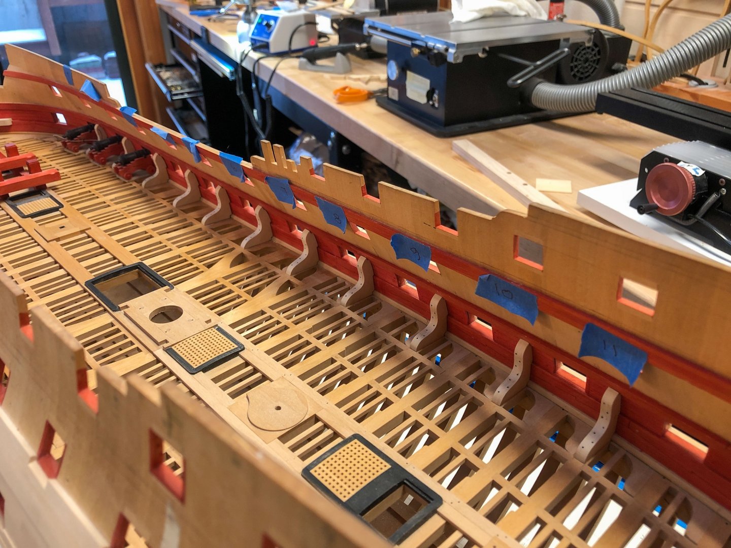
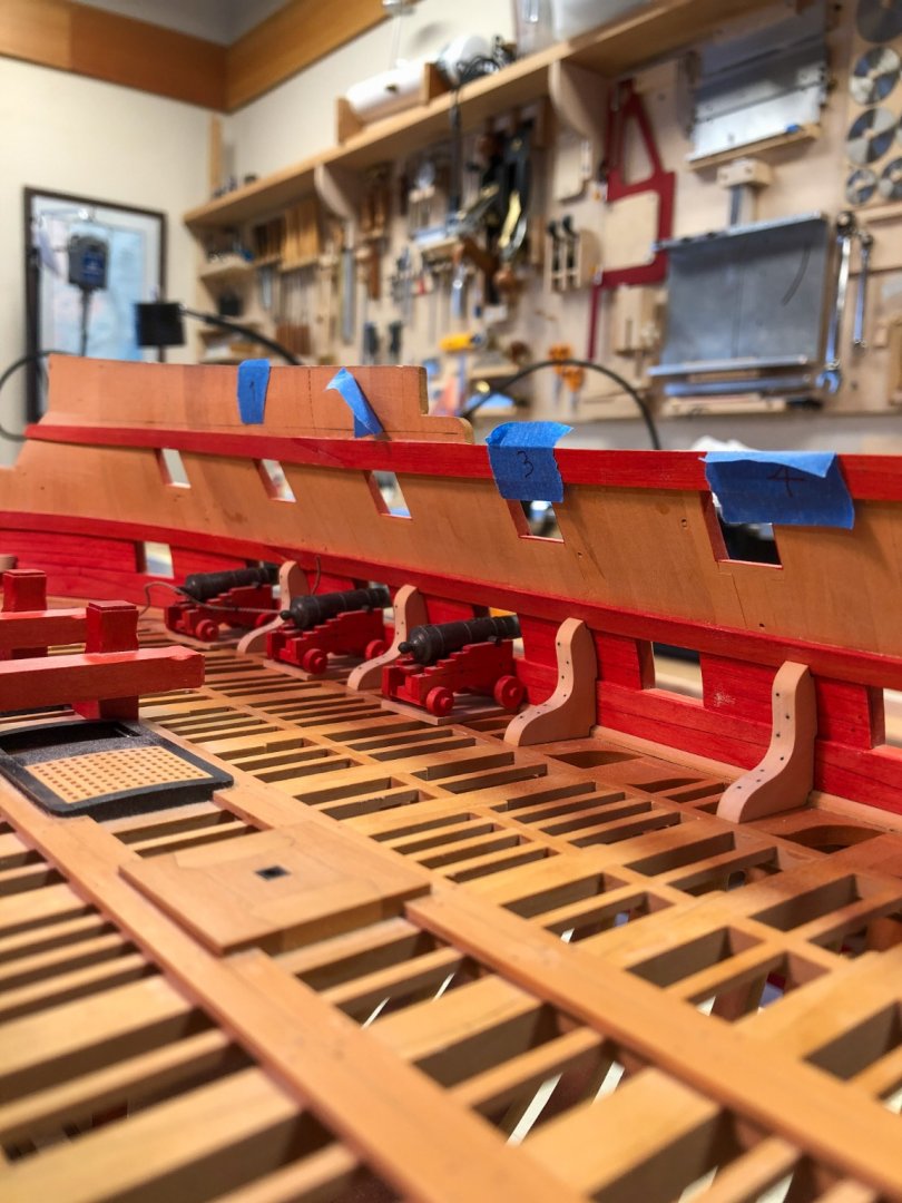
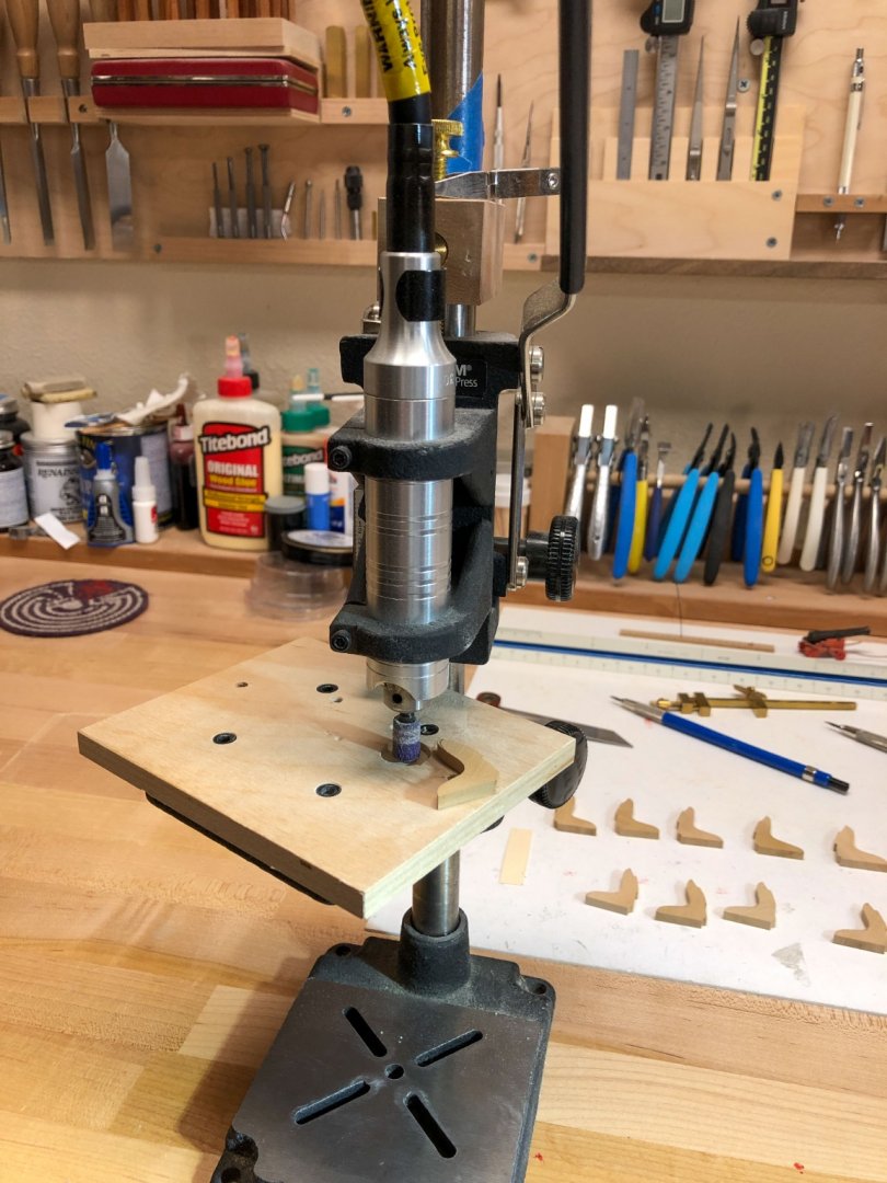
A patient day of final shaping of the standards, and making bolts. Starboard done today, port tomorrow. then clear finish and final installation at last! The Foredom drill press converted to a sander worked very well for final shaping.
-
If you are starting with thick blanks of expensive wood (mine are 3/4" by 3" by 24"). and need to rip these down to more suitable thicknesses, I agree it is less wasteful to use a bandsaw, then use a thickness sander like the Byrnes to clean up. Use a broad blade used for resawing, like the 1/2" Wood Mizer. I gang up feather blocks pressing against a fence for the entire width of the blank; keeps things parallel. Using a table saw safely with these small pieces, in my experience, requires using a jointer to get a straight face to put against the fence, which is another source of waste. A bandsaw deals pretty well with a not perfect face against the fence, particularly if you are later thickness sanding. Mark
-
Thanks, Gary, that sounds as definite as I need to omit the standard. I guess there are a few compensations for building a ship in the early mid 18th century; more stuff appears later on, like the sweep for the tiller. It makes my project downright easy!😊 Best wishes, Mark
-
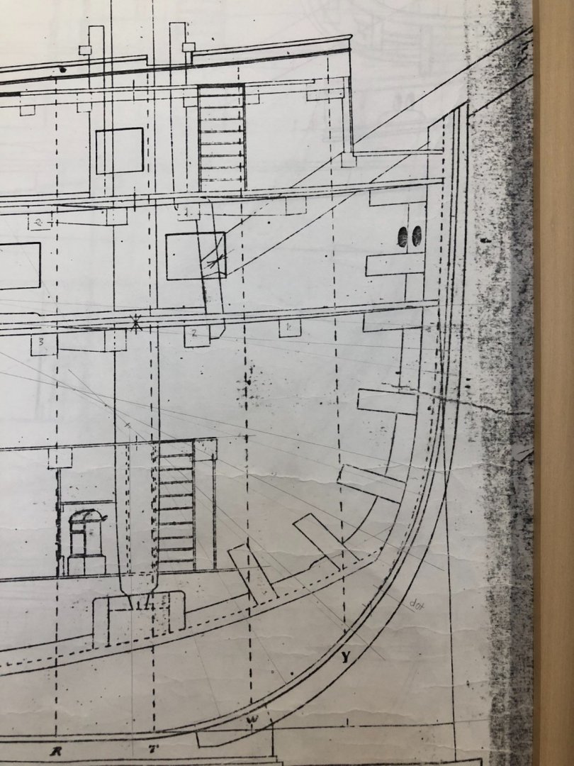
Hi Gary, Well spotted. So here is an example of an apron up to the upper deck, and also a standard on the gundeck. So the question is whether this was done around 1760, or came in later, by 1780. You have all found enough examples around 1780 to make it pretty clear this was normal by then. Might be a toss-up for the Bellona. Either it was normal practice, just not shown on the Bellona or Dorsetshire sections, or it came later, maybe as the gundeck lengths increased? I might rough one up, and see how it looks. At the rate I am going, the gundeck will still be open a long enough time that we will find clearer evidence for me to make a final decision. Maybe too late to make a split apart hull like the one at Annapolis! Best wishes, Mark
-
Thanks so much, Alex, Alan and Gary. This research is endlessly fascinating! The Bellona project is particularly challenging, because the original Admiralty drawings had very little detail, much less than I see in these later draughts. And as I read elsewhere on this website, the absence of something in the archeological record is not proof of its actual absence; so I cannot assume that if something is not drawn in the Bellona draughts, it does not exist. So it is particularly interesting to hear of the pattern Alex identified, and Gary confirmed, that there seem to be two different approaches to reinforcing the stem. One has the false stem or apron going all the way up to the upper deck breast hook, and no standard; and the other has the false stem stopping at the gundeck breast hook and then includes a standard on the gundeck. Two schools of thought. Based on that pattern, I see that the Bellona draught (below) has the false stem going up to the upper deck breasthook, and therefore would not have a standard. If a drawing ever shows up circa 1750-60 with a false stem up to the upper deck breast hook, and also a standard on the gundeck and a breasthook just under the hawse holes, then I will reconsider. but until then.... I am humbled at how sharp-eyed you all are, to see these issues and patterns. And I benefit from it; thank you so much. And by the way, Alex, your drawings of the Anson are as detailed and as beautifully drafted as any I have ever seen. You are a master, and you have inspired me to improve my own drawings of the Bellona. You set a very high standard! Best wishes, Mark
-
thanks so much Gary, I am wondering about the time issue as well. Although it sure would make sense to have a knee at the stem. I saw an episode of the rebuild of the Tally Ho, and his stem was slowly leaning forward until he got it anchored back to a breast hook. A standard would help even more. But if I can't find an example in my timeframe, I may skip it. As long as we are looking at the fore end of the gundeck, how about the stoppers for the anchor cable/messenger? I see these referred to, and even found the size of the stopper bolts, but where exactly were they, and how many? I saw a reference to "a couple behind the riding bitts", but nothing else. After that and scuppers, I THINK I have accounted for everything on the gundeck.....🙃 Best wishes, Mark
-
Aha, thanks, Gary. So the standard and the breasthook can go together. Thanks for catching that for me. So you drilled into the trucks from underneath, to fit a pin which aligns with holes in the deck. Ingenious! Best wishes, Mark
-
Mike, nice tool construction! You could patent that Turbo Buzzr 3000 logo. Sweet! Mark
- 968 replies
-
- 2
-

-
- hahn
- oliver cromwell
- (and 1 more)
-
Sure enough, Alan, there it is listed. Thanks. Hmm, the contract doesn't match up with the drawing of the Dorsetshire, where the standard against the stern post is drawn, but not one against the stem. And the Dorsetshire shows a breasthook in this location. Lavery's drawings of the Bellona in his Anatomy of a Ship are too sketchy to see it either way. With the Bellerophon contract calling for an up and down arm of 5'-6" on a standard at the stem, there would be no room for a breasthook in this same location. Could this have changed from the Dorsetshire (1757) and Bellona (1760), to the Bellerophon (1786)? from National Maritime Museum "https://upload.wikimedia.org/wikipedia/commons/c/cf/%27Dorsetshire%27_%281757%29_RMG_J3113.png"
-
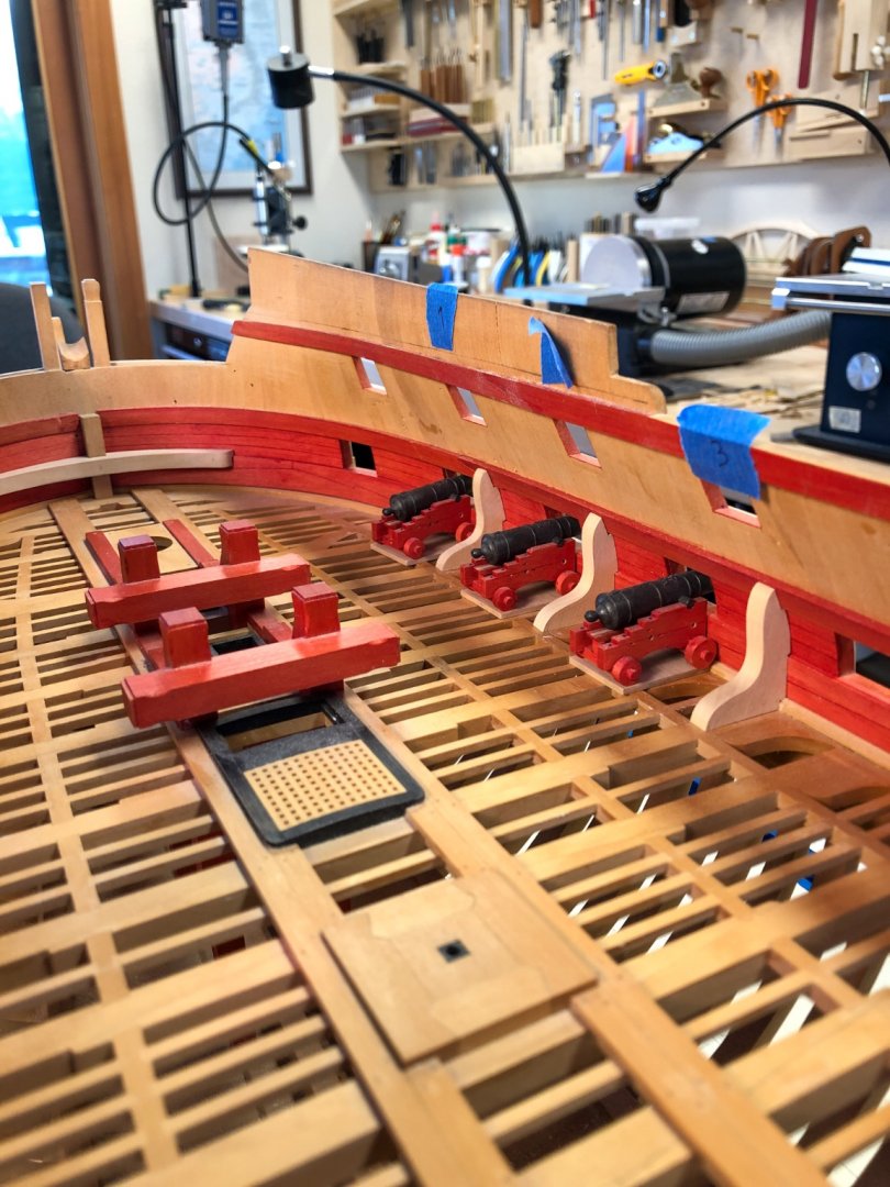
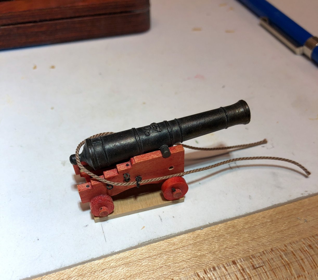
Hi Gary, I was not aware of a standard at the stem. I see a breasthook but no standard in Goodwin on page 178. Same in the Dorsetshire cross section. I assumed the breasthook was needed for the cants and bucklers covering up the hawse holes, as in David Antscherl's Fully framed Model vol. II p. 78. But then I completely missed the schols, so I still have lots to learn! So are you planning to install the gundeck guns permanently, and then just work carefully around the barrels sticking out as you proceed building upwards? Very nice capsquares on your gun carriages, by the way. Very finely detailed! Best wishes, Mark
-
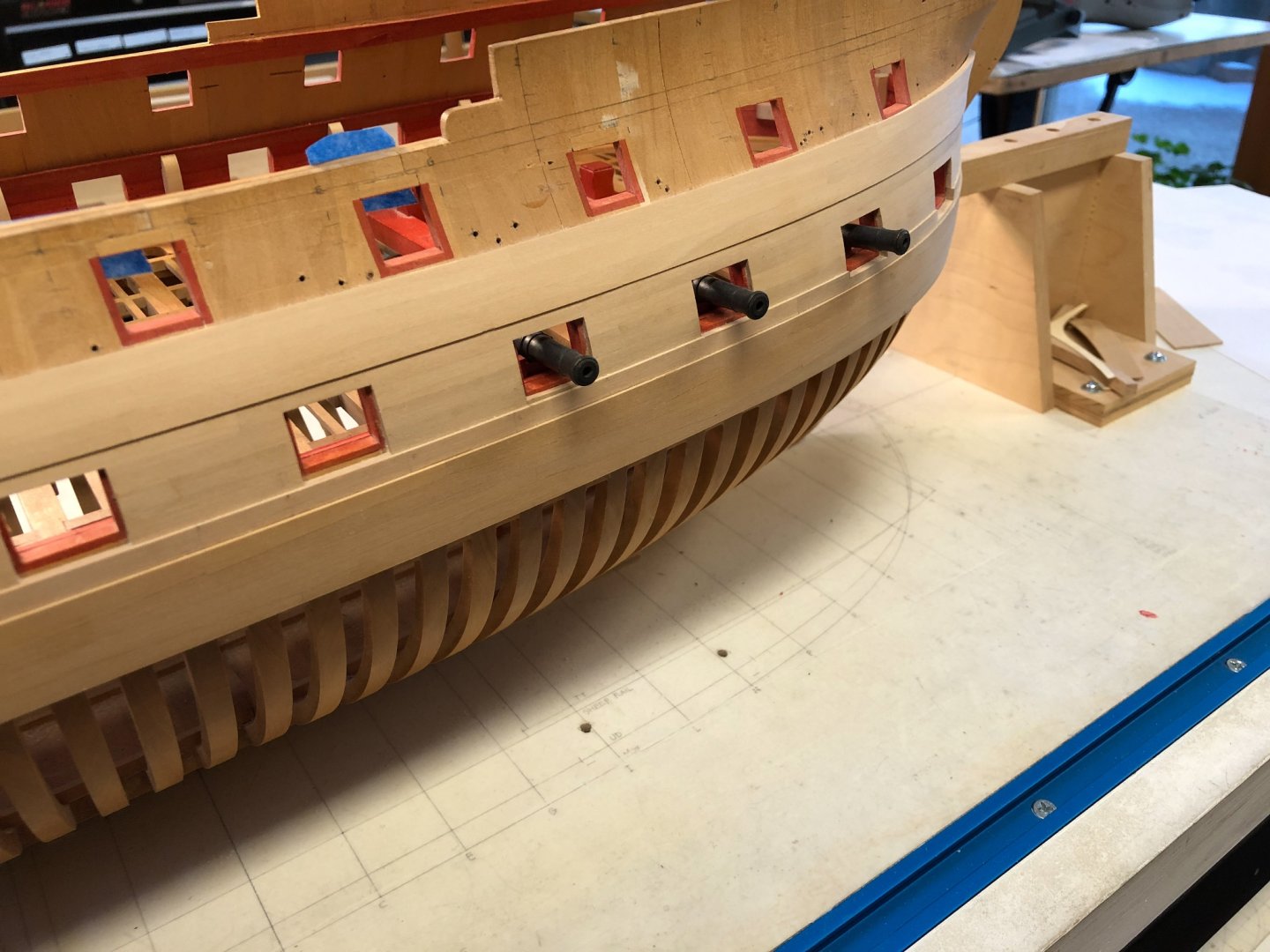
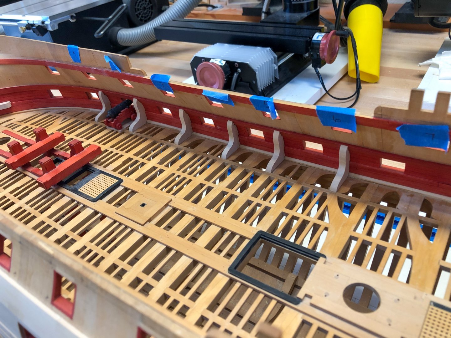
Thanks, Alan, you make me feel a little better! I have worked periodically through the holiday, making more standards for the gundeck. Only 8 out of 22 to go. As I approach the end of this, I am thinking ahead to another challenge, explained in Rob Napier's Legacy of a Ship Model book as the "Chinese Puzzle Effect". You have to do A before B, but A cannot be done until B is completed. I am getting to the point where the guns have to be installed, before I can eventually proceed to the upper decks. But the cannon barrels sticking out are clearly going to get in the way of further outboard work, including planking to the top and painting the wales and friezes. The outer work needs to be done first. Also, cutting all of the mortises in the clamps for the upper decks will make a mess of dust falling into the cannon on the gundeck. So these need to be cut before installing the cannon. Indeed, just about everything following is in danger of knocking about or dislodging altogether any cannon sticking out of a gunport. I am beginning to wonder if I should install the carriages now, and only towards the end of the project slide the gun barrels in through the ports and then fasten them down. I can't imagine how I bolt the carriage capsquares down onto the barrel trunnions, when I no longer have access from the inside; working entirely through the gunport. And the breech ropes would have been installed along with the carriages (because the rope goes through a ring on the carriage) long before I try to slide a barrel through a gunport; how would I get that rope to fit nicely onto the barrel cascabels, working from outside and not from within? By the way, I have decided not to plank the outboard edges of the gundeck as a platform for the guns. I really like seeing the lodging knees. So I will make a little 4" base under each gun, which will allow me to pin from underneath into the trucks of the carriage, and then pin the platform down to the beams. I am worried about these coming adrift over time, especially with the vulnerability of the barrels sticking out. So some major anchoring is needed. Hmmmm......complex problems, these ship models!
-
Marc, truly magnificent work, and thoughtful conjecture based on impressive historical research. Outstanding. Mark
- 2,696 replies
-
- 5
-
-
- heller
- soleil royal
- (and 9 more)
-
Thanks, Gaetan, that is very interesting and helpful. Mark
-
Gaetan, the second photo (Sony 200-600) appears sharper on my computer screen. Is it the same sharpness for both photos? Mark
-
Gary and Alan, thanks to both of you. I have probably looked at that Steel print a dozen times or more, and never noticed the shole or the bevel at the inner corner of the standard. and Alan I read your transcript a few years ago and never remembered that reference. Can I put this all down to an aging brain? By the way, I was looking at a video on YouTube the other day of someone thoroughly walking through HMS Victory. I did not see a single standard on any deck. Interesting. Mark
-
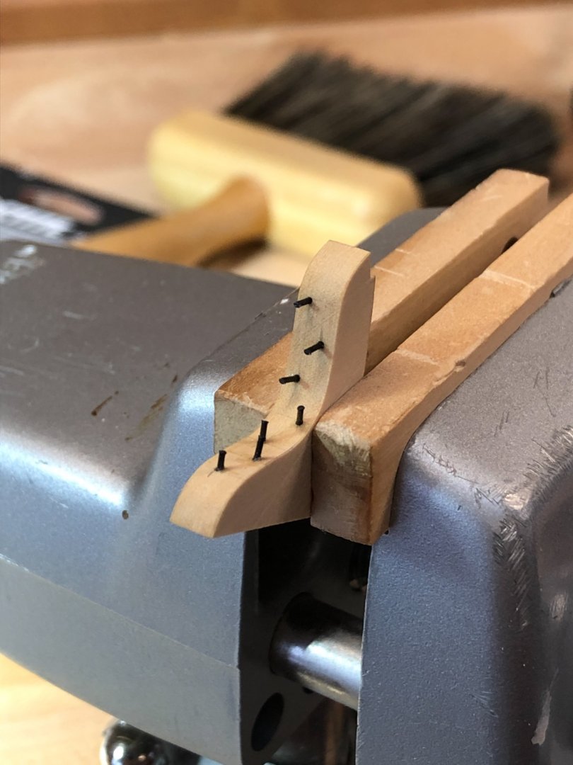
Hi Gary, I forgot to answer your question about the bolts. Yes, I was thinking I need to anchor these with real trennails, disguised as bolts. I think these might come adrift over time without a mechanical fastening. Did you actually pin yours, or or those false bolts? Yours are pretty uniform in location; did you use a jig of some kind to locate these? Mark
-
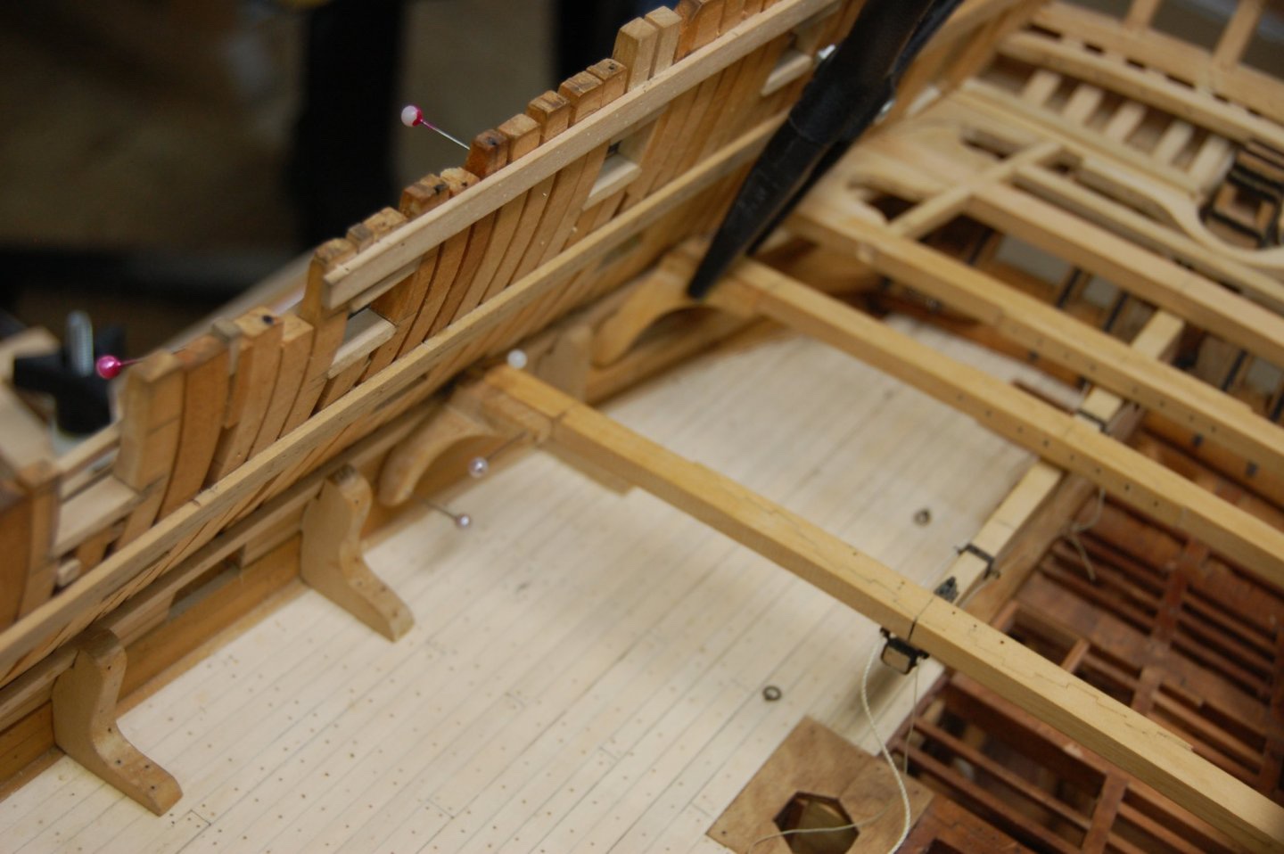
thanks, Marc, my wife is a retired architect/furniture designer, and she came up with a pretty ingenious tree design. It saves vacuuming up needles at the end of the season.... It just hinges flat and goes into the basement. druxey and Gary, thanks for the alert about sholes/soles. I am guessing that these were like a false keel, something that, when damaged, could be stripped off and replaced without having to replace the whole thing. I imagine that pools of water collected at the bottoms of the standards even with small drainage holes at the waterway, leading to early rot. Those standards were large, expensive compass timber, 1'-0" by 5'-9" by 3'-6", not something the shipwrights would want to throw away if only rotted at the bottom. No end of things to learn! I may do a SWOPEM on this detail, since I am already not accurate with my standards coming straight down onto the beam rather than on to non existent planks. I am planning to plank part of the upper deck, so the standards up there may be more authentic. If my standards look half as good as Gary's I will be happy. You have set a standard 😉 for me! Mark
-
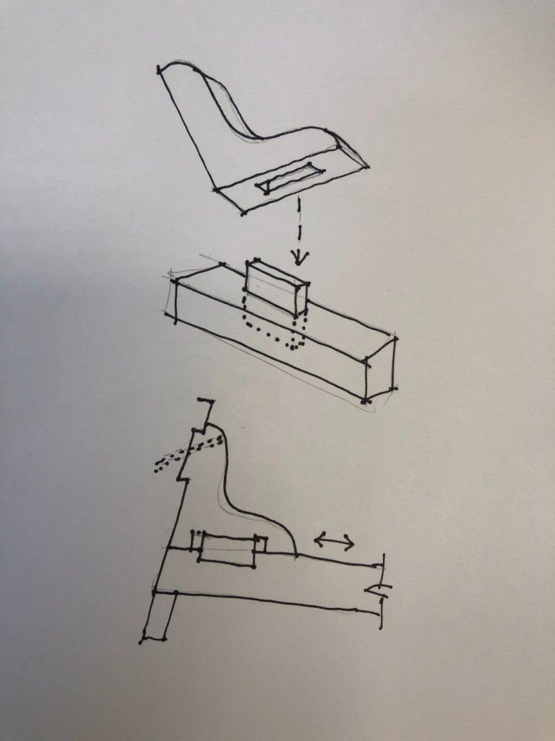
Hmm, what are the sholes/soles. I haven't come across those. I realize that I have the standard sitting on the beam, when in fact it would be sitting on the deck planks. I thought about putting a little piece of plank as a separate piece, but thought it would look a little messy. Is there something else that is between the planks and the standards? Mark
-
Gary, Here is one of the photos from your project. it looks like the gap is just a bit clear of the waterway in both width and height. Is that right?
-
Hi Gary, Just saw your post as I was posting my second one. No, I did not know that there is a space between the standard and the waterway. It makes perfect sense, though. That would make this a very much easier process. Getting that tight was the slowest part. Do the photos on your site show the gap shape and size? Yes, I have copied your process, fitting first to the beam, then slide up to fit to the side, then cut the curved profile when everything is properly fitting. It sure makes things easier for me to be a number of steps behind you; I get to learn from your solving the problems first! Best wishes, Mark
-
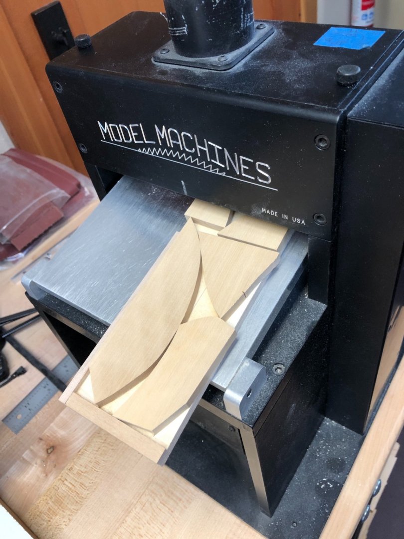
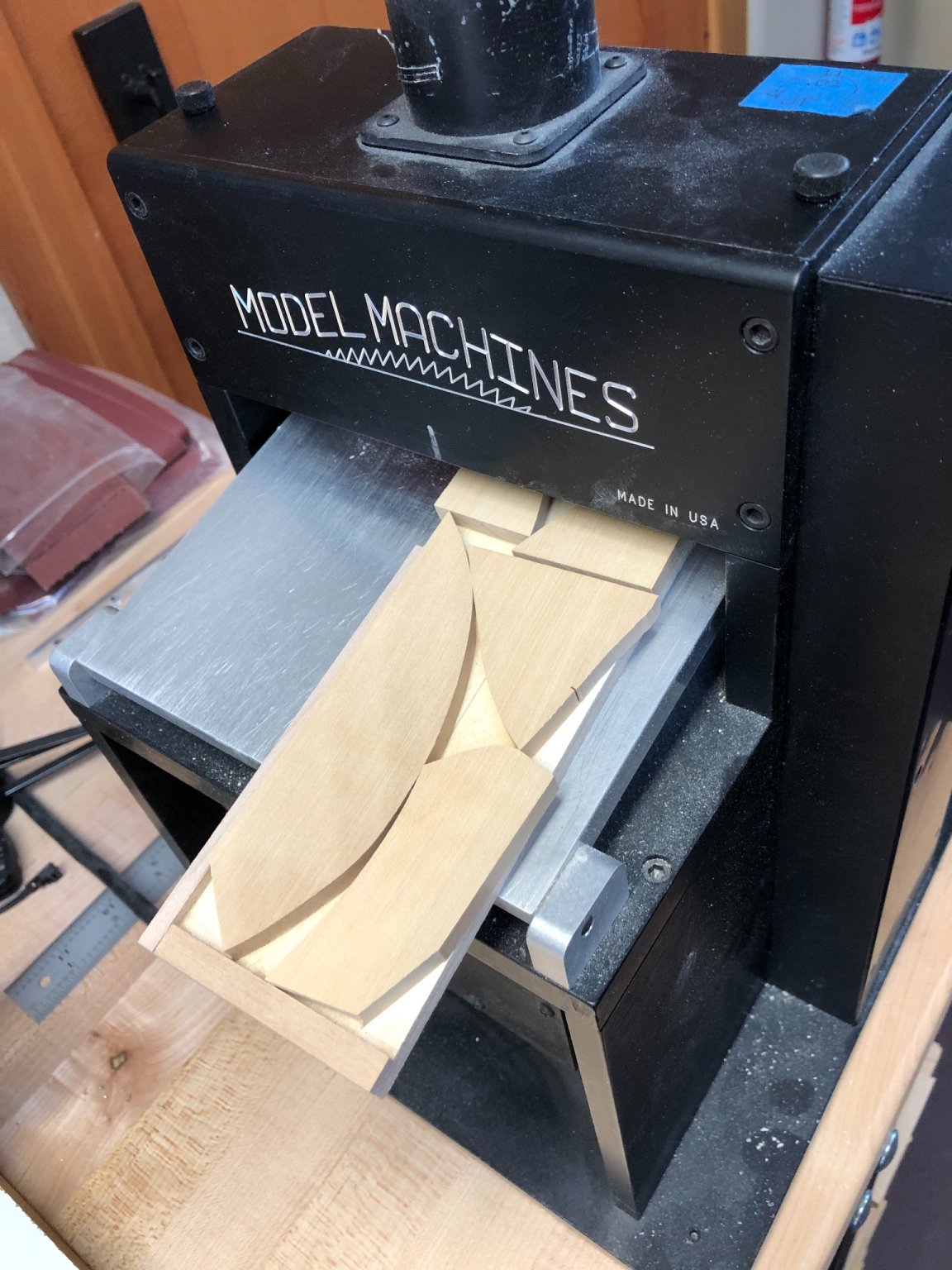
Thanks, druxey, and at least the ones towards midships are not as angled in both directions. I forgot to mention that for the knees I decided to use up old cut-offs of boxwood from the hull frames that have been lying around for years. The biggest challenge was siding and then sawing out their profiles. The pieces were too small to run through the thickness sander, or to cut on the power scroll saw. I built a little sled for the thickness sander, and stuck them down with double sided tape. I measured thickness using the digital caliper's depth gauge. And a fret saw and a bench pin made quick work of the sawing. Less noise, very pleasant....