HOLIDAY DONATION DRIVE - SUPPORT MSW - DO YOUR PART TO KEEP THIS GREAT FORUM GOING!
×


SJSoane
-
Posts
1,649 -
Joined
-
Last visited
Content Type
Profiles
Forums
Gallery
Events
Everything posted by SJSoane
-
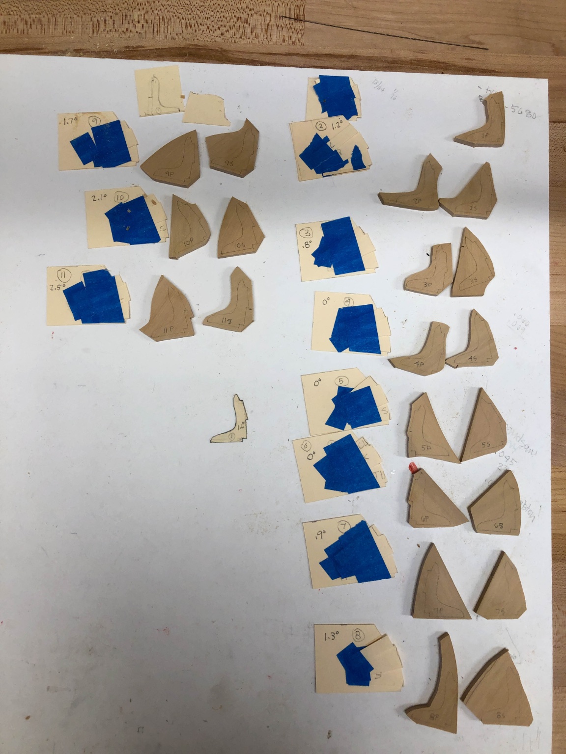
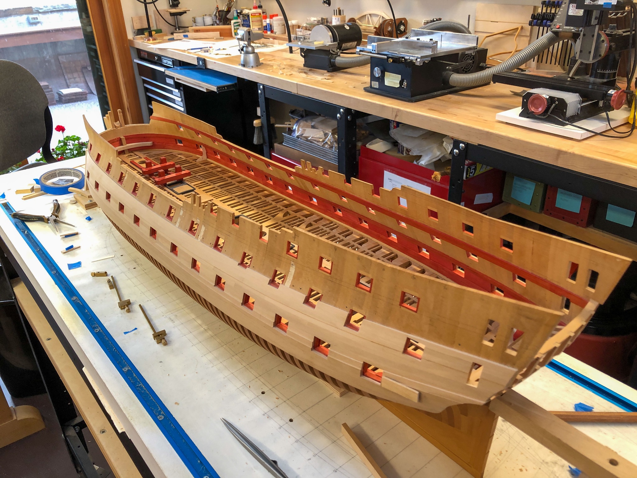
 The Christmas tree I built to my wife's design.... Now on to the real stuff. I started on the standards on the gun deck, which I remember Gary saying was really tedious. Now I know why. It was a full week, making the patterns of individual pieces taped together--thanks Greg and druxey, I think this was your idea originally. Then siding and rough cutting the blanks, then measuring the angles of the deck sheer and the curving in of the hull side at each point. And finally, shaping the first standard. It only took me about 4 hours, and just 21 still to go! I am sure it will get faster--won't it? I was thinking about leaving them and the breasthook natural wood rather than staining red, but now I am not so sure. I will put in a few more, along with the gun carriages, to see the overall effect. Mark
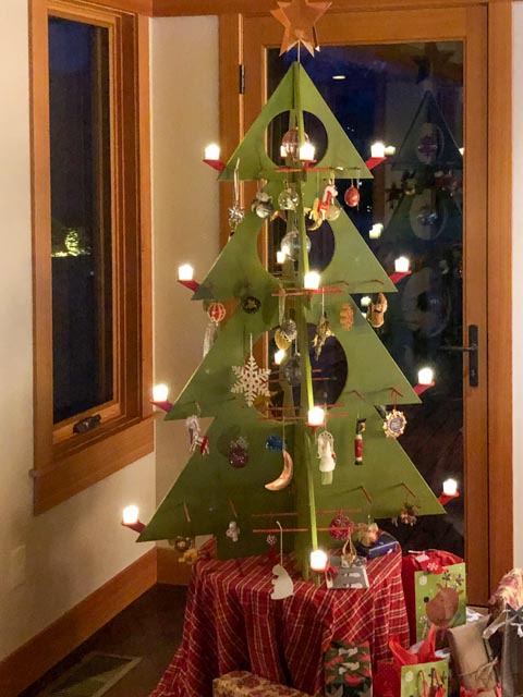

-
Hi Remco, I join everyone else in wishing you the best in finding your way forward. You continue to provide inspiration for me, when I look at your build, and I think every day about your great tagline, "Treat each part as if it is a model on its own, you will finish more models in a day than others do in a lifetime." It keeps me going through the slow times! Looking forward to your eventual return to the shipyard, Mark
- 1,214 replies
-
- 4
-

-
- sloop
- kingfisher
- (and 1 more)
-
Gary, that is an interesting deck plan. Is that the gundeck, coming to a point at the stern? The transoms must have been very high... Mark
-
I just saw this. Beautiful work, both plastic and wood. Particularly nice shield! Mark
-
Oops! I had temporarily attached a wooden pad to the side for clamping in the last piece of quickwork without damaging the wale. I forgot to take it off before I took the picture. It could be used as a spare rudder, perhaps, like on a Viking longboat?🧐 That reminds me that I don't know how I would have built this without those handy gun ports providing endless places to clamp. I can never do a merchant ship.... Mark
-
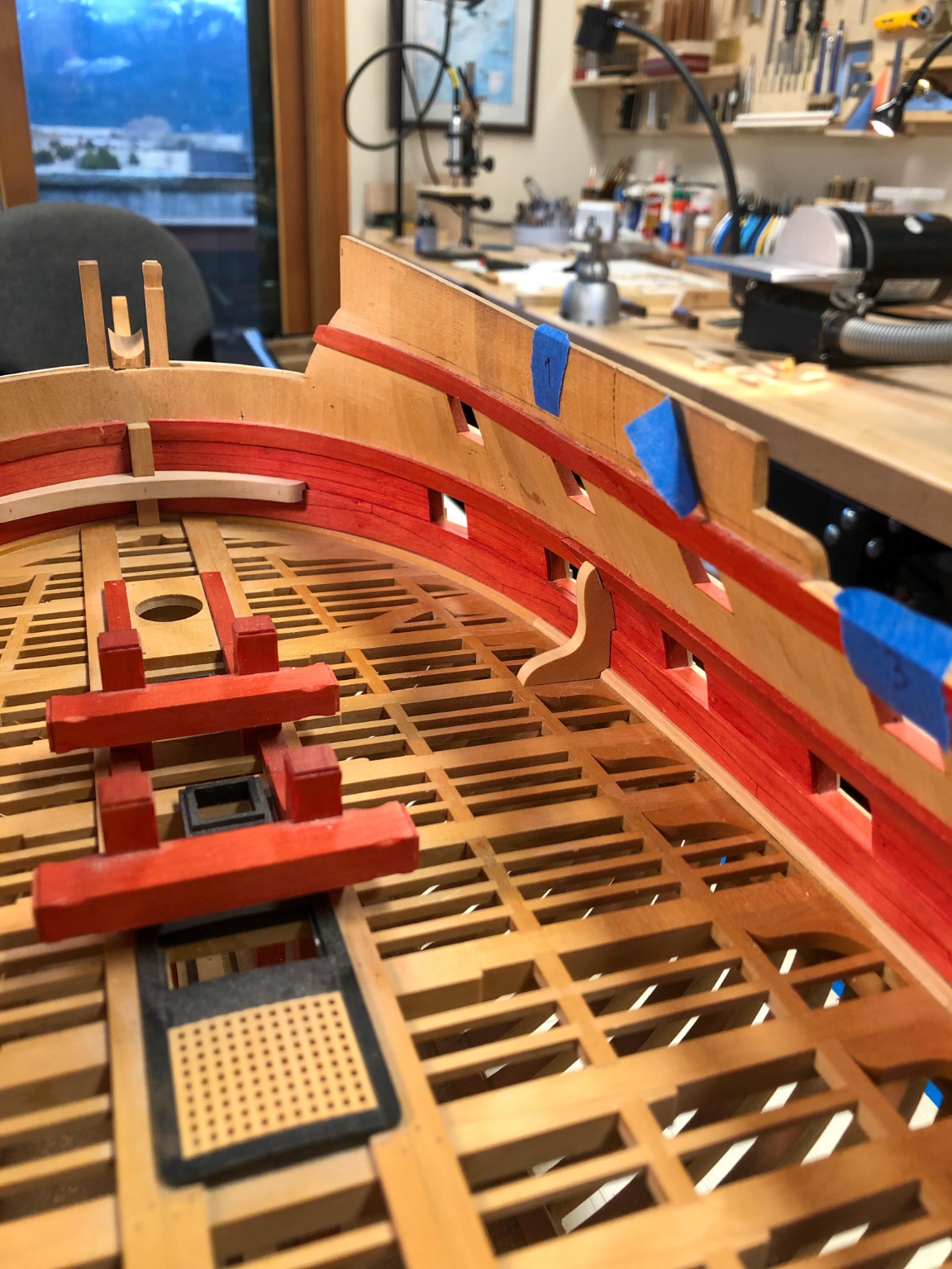
Hi Gaetan, I am coming to the same conclusion, that the rules were something to aim towards, but not something that could be followed without adjustment. There are too many conflicting rules: 1) a beam under every port; 2) no excessive curved, compass timber in knees; 3) knees relative to fore or aft side of a beam different fore and aft of midships. Not all rules could be followed in every location. So it is up to the experience and judgement of the shipwright to find the best compromise among all of the rules. Thank you, stuglo, for your kind comment. Gary, I posted something on your postings about this. Also, I will look at whether I can get a hanging knee near the sheave for the tiller. And regards the tiller sweep, I am relying on Goodwin's Construction and Fitting book that the sweeps did not come into use until a few decades after the Bellona (1760), so I am having to do sheaves on the sides and ropes straight from the tiller to the sheave, and back to the sheave taking it up to the quarterdeck. I understand the tiller ropes go slack at some point in this older system, which eventually I will find out when I built it. And, here is the starboard quickwork completed, and a template starting for the first standard. Once the red goes all the way up through all three decks, it is going to look like a red velvet liner inside a jewelry box! Mark


-
Hi Gary, You have done some remarkable research in some difficult to find sources. This is so interesting and helpful. I am beginning to understand what a difficult business it was for the shipwright to lay out the beams. So many different issues to address, like one under each gunport, making way for hatches, partners, etc, not causing problems with acute angles in knees, or excessive casting of knees. I also begin to see that no one rule could be fully carried out without violating another rule. The Bellona, for example, does not have beam under every port, and avoiding excessively cast hanging knees means violating the rule about which side of the beam the knee attaches to fore or aft of midships. So I am beginning to think that all of these rules were ideals to aspire to, but the circumstances of individual ships meant that some rules would have to abandoned in favor of other rules in certain situations. I don't yet see a pattern in the drawings or sources we have been looking at, to suggest which of the rules was always most important. It does seem to be using judgement in individual circumstances as how to best balance them all. I also wondered, in my own case of the Bellona, whether shipwright Thomas Slade had not yet perfected the design of a 74, and so was creating some problems that he worked out in later ships. The gunports are very irregular towards the stern on the Bellona relative to other later 74s, for example. Maybe the beams got more organized later on. But I haven't really looked at later ships in detail to see if this is the case or not. Just my first thoughts about what we are learning here! Best wishes, Mark
-
Coming from you, druxey, that means a great deal! The toughest part of the exam was calculating the displacement of the hull by 18th century math techniques...🙃 Mark
-
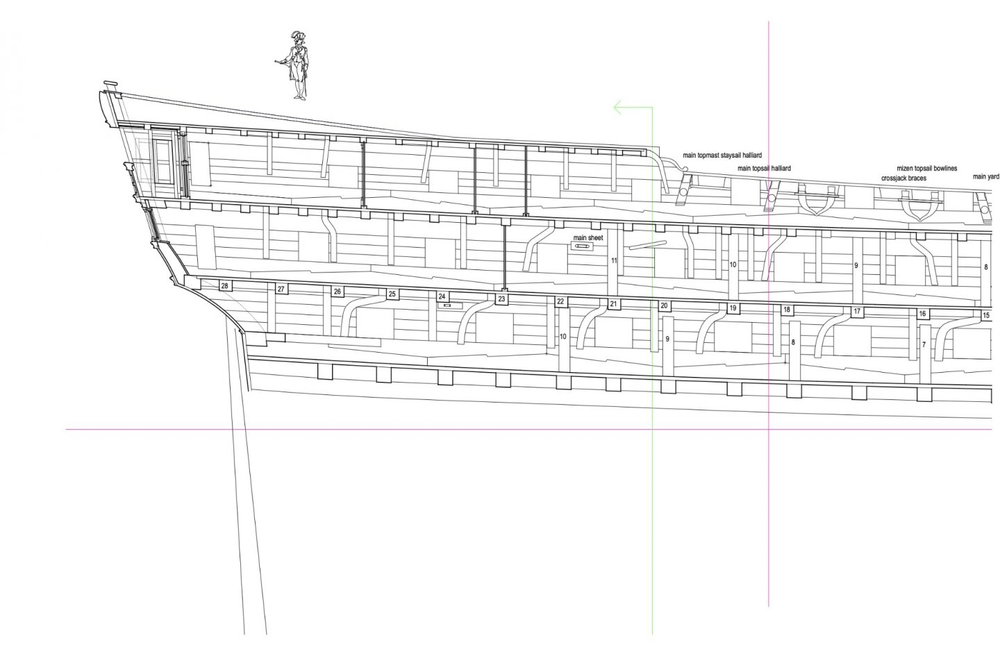
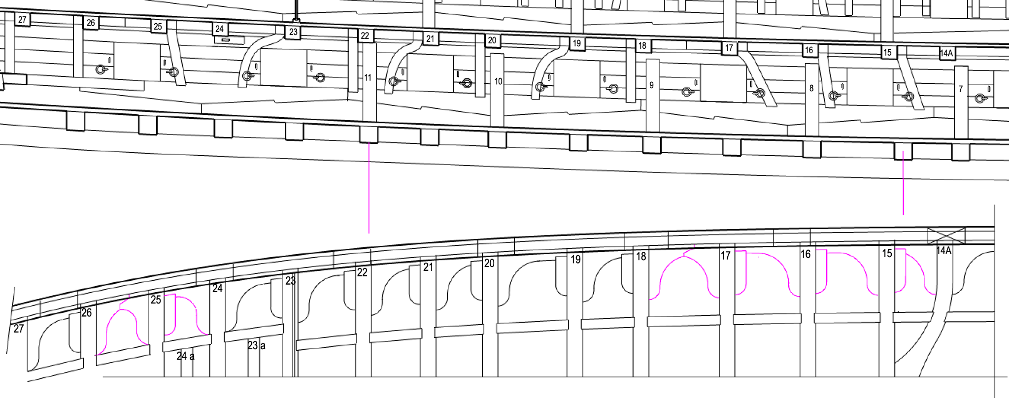
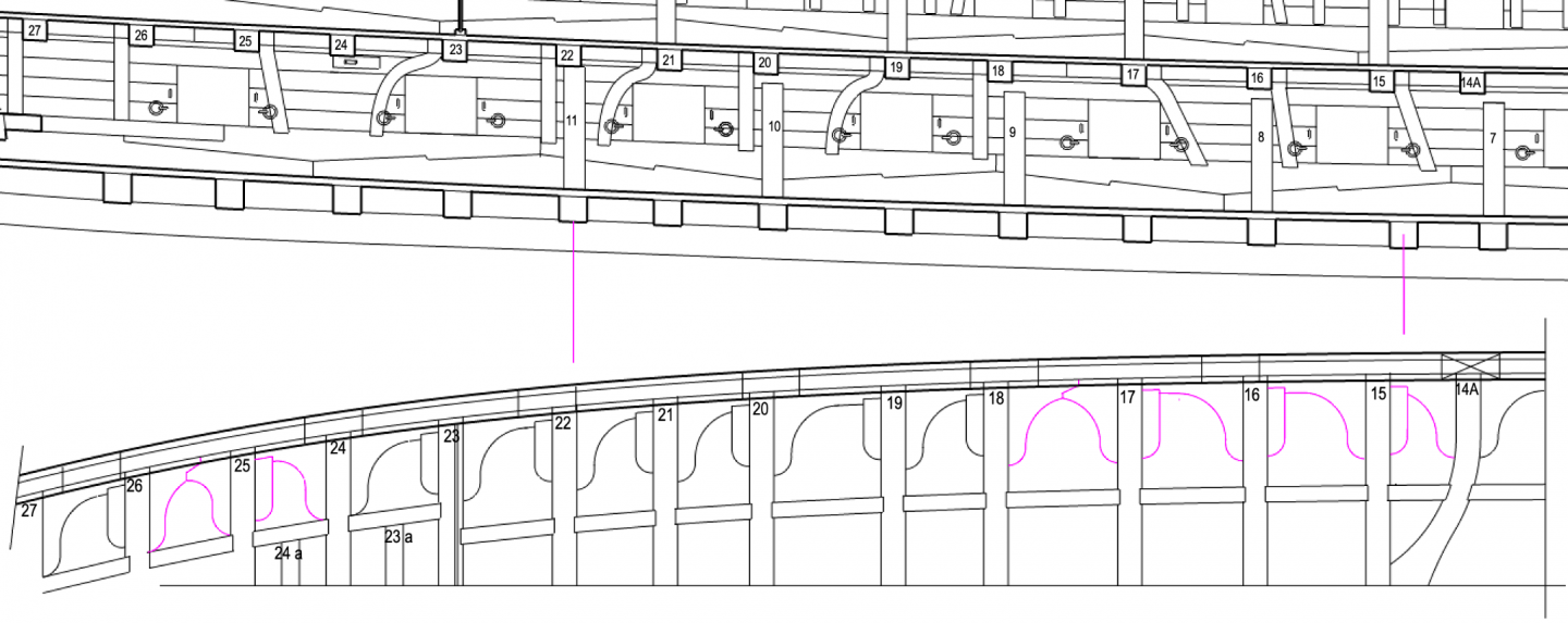
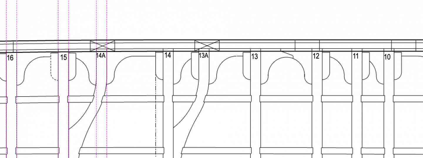
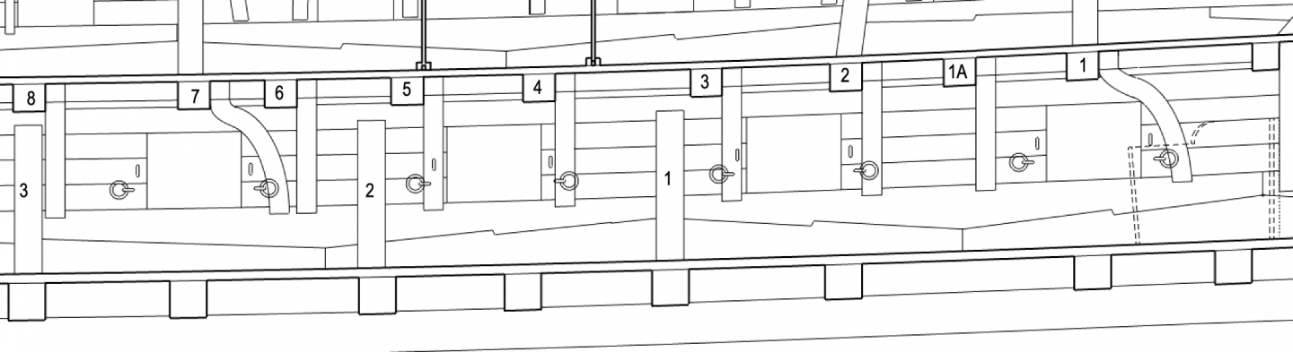
Gary, thanks so much. Your attached drawings showed me the way, I think. Inflexibly following the rule of hanging knees aft of the beam when aft of midships, I had to create very large and even improbable compass timber knees. Once I saw in your Hector drawings that the shipwrights periodically shifted to the fore side of the beam when needed for other reasons, it gave me the freedom to simplify the knee shapes and locations. In the drawing below, the purple shows where the knees violate the general rule, but simplify the construction. By the way, I looked again at the Dorsetshire plan, and it also shows places like this where two lodging knees fill the same space without hanging knees. The most extreme compass timber on a hanging knee is at beam 23. But I left a hanging beam off of 24 to leave room for the sheave in the side for the tiller rope. So running the hanging knee at 23 aft seemed to give a little more structure to this area of the hull. I don't know about the general pattern after about 1760, but within this period there was definitely some flexibility with the general rule, for good constructional reasons. Thanks again, Mark
-
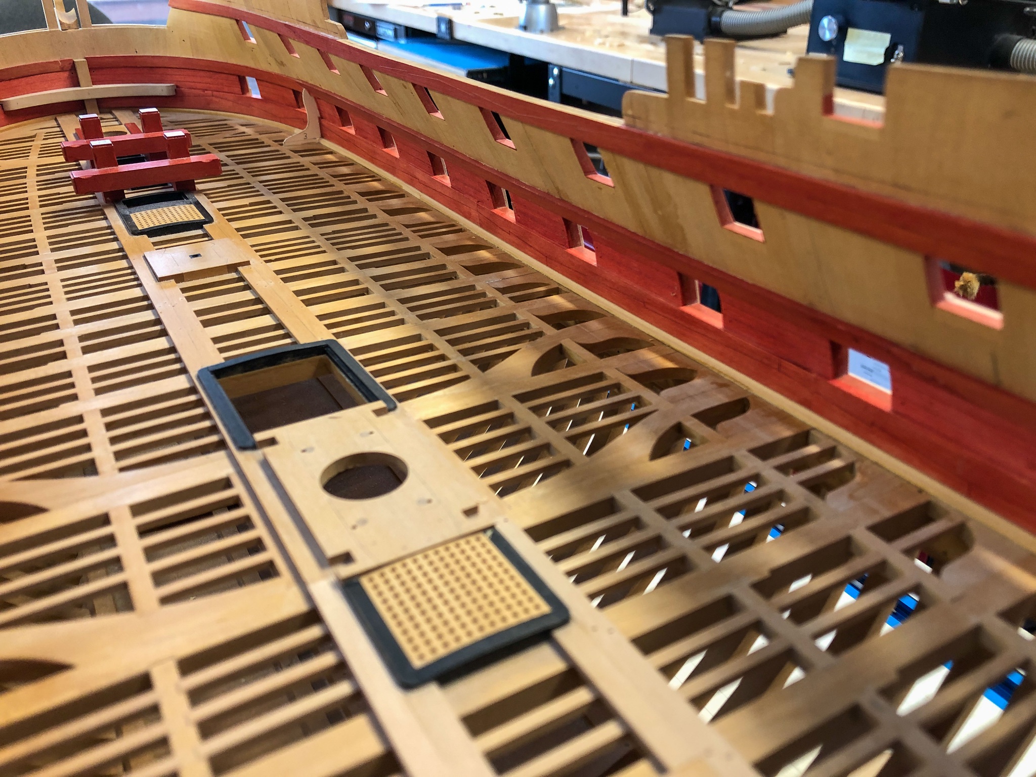
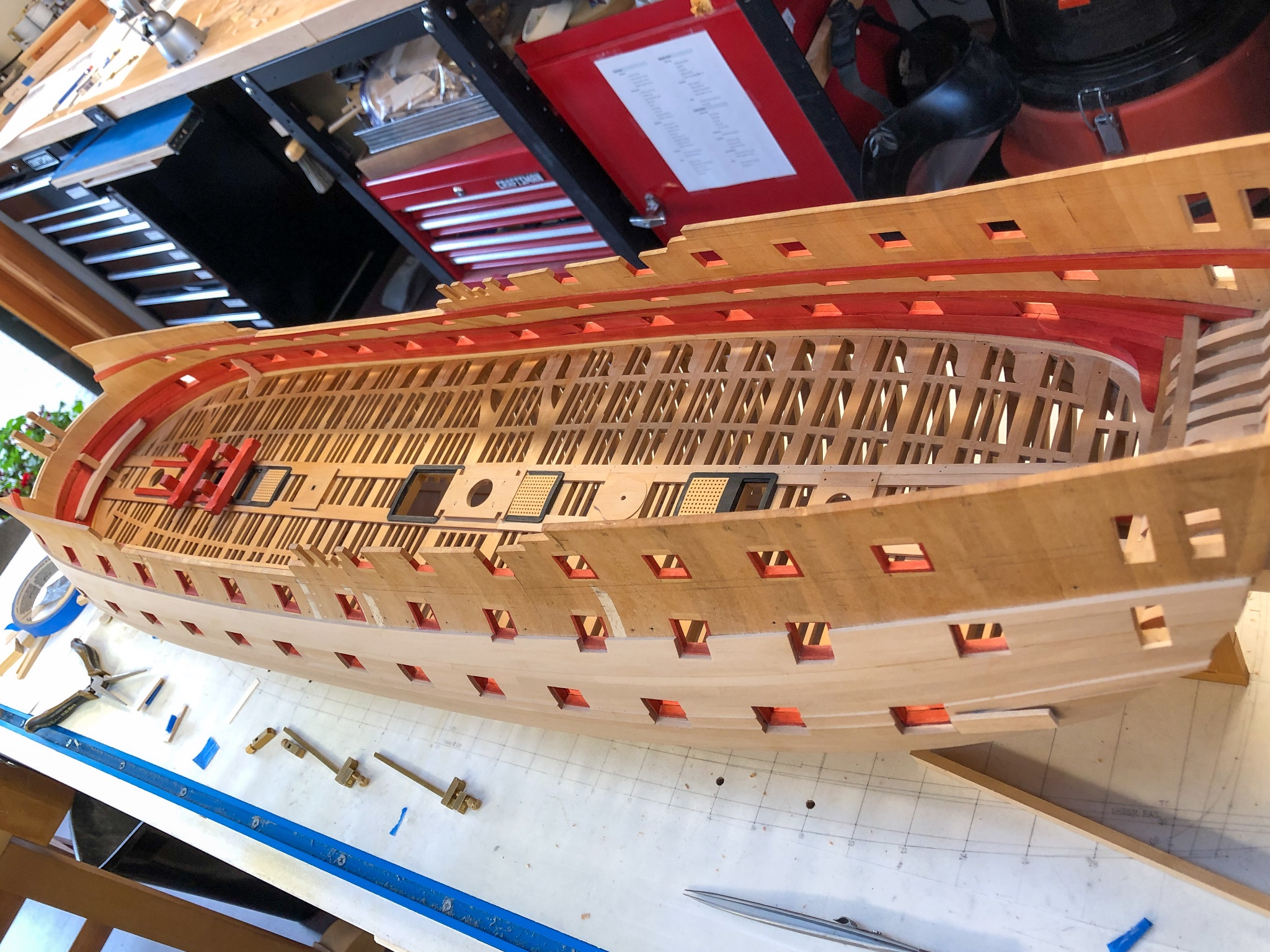
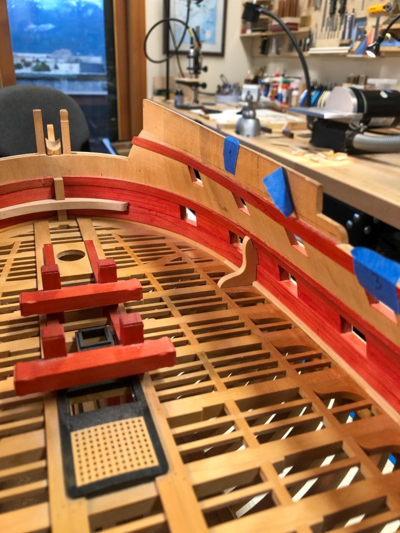
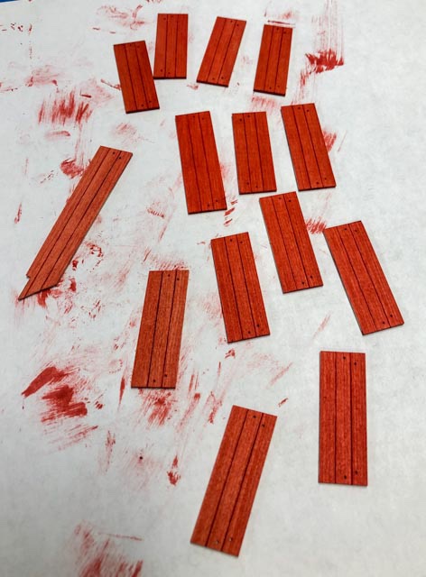
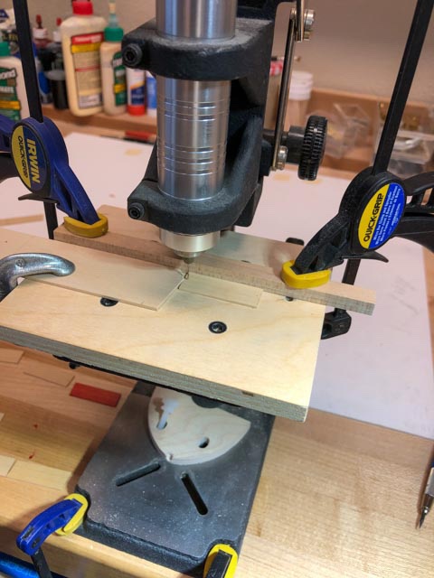
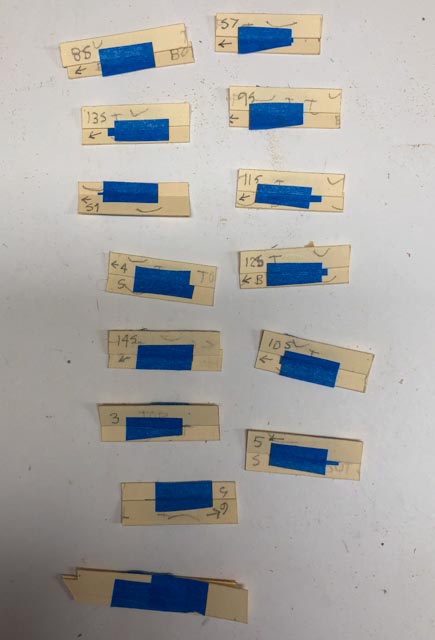
Enough drawing; here are the first images of the quickwork being installed. The red is looking very dramatic. Also note the thickness of the hull at the gunports. That was some substantial work. The quickwork became quicker when I took a clue from Greg Herbert and David Antscherl, making up card patterns from multiple pieces. I taped a piece to the top of the spirketting that was not the full height of the quickwork; and then another piece under the clamp above, taped to the lower piece. When I pulled this off, I had the exact shape and width of the quickwork needed. I traced onto the wood, and bob's your uncle. The biggest challenge was keeping the notes clear on each piece as to which way is forward, and which edges are concave or convex. I also set up a little drilling jig for the eyebolts. Since the quickwork pieces were not uniformly the same width and had different angles cut on the ends, I set the fence of the drill the desired distance up from the lower edge, and a stop that was pointed at the exact height above the lower edge needed for the hole. That way, different pieces were always registered at the right distance up and out from the lower edge of the port. And finally, scoring and staining Mark

-
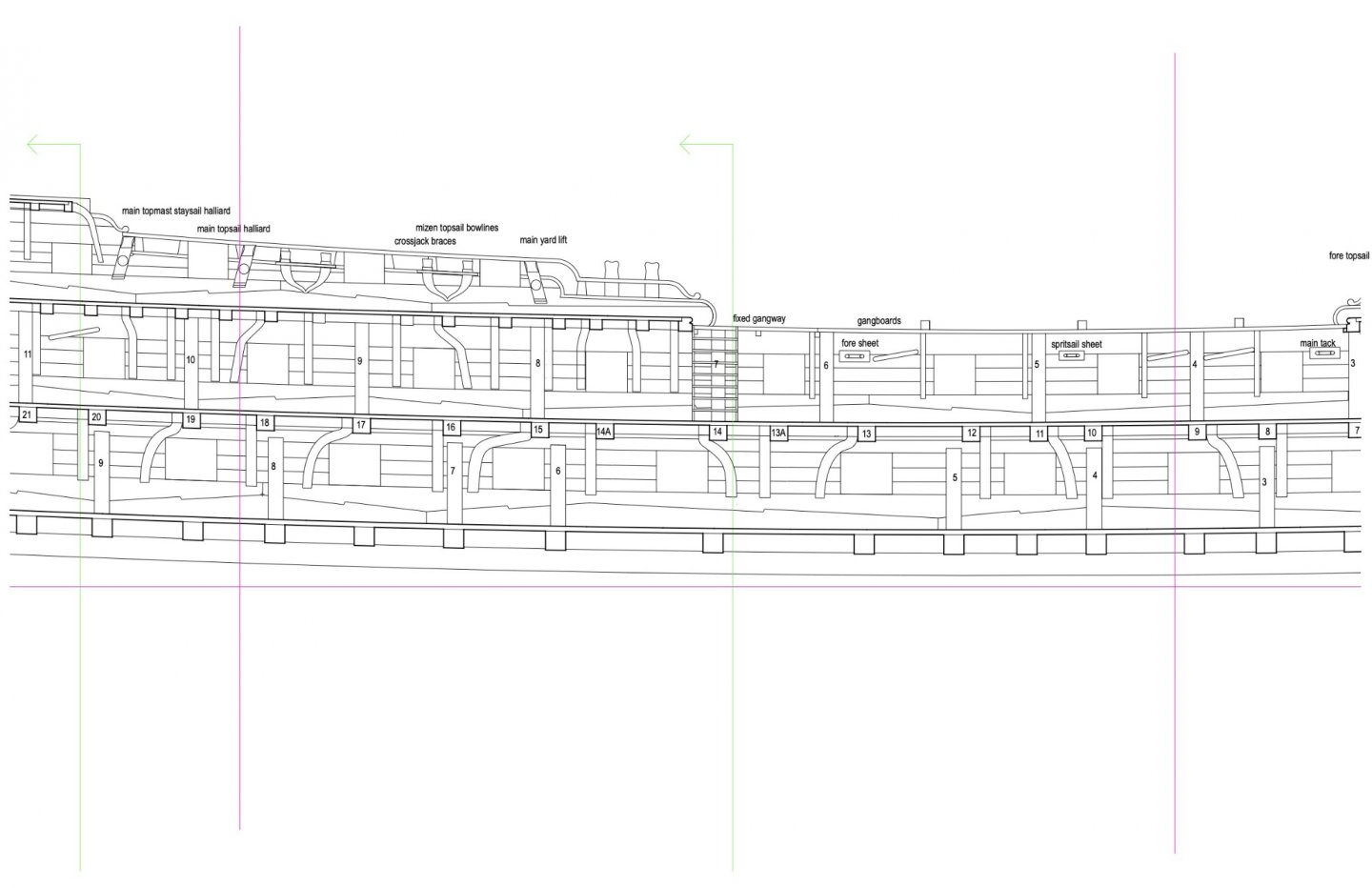
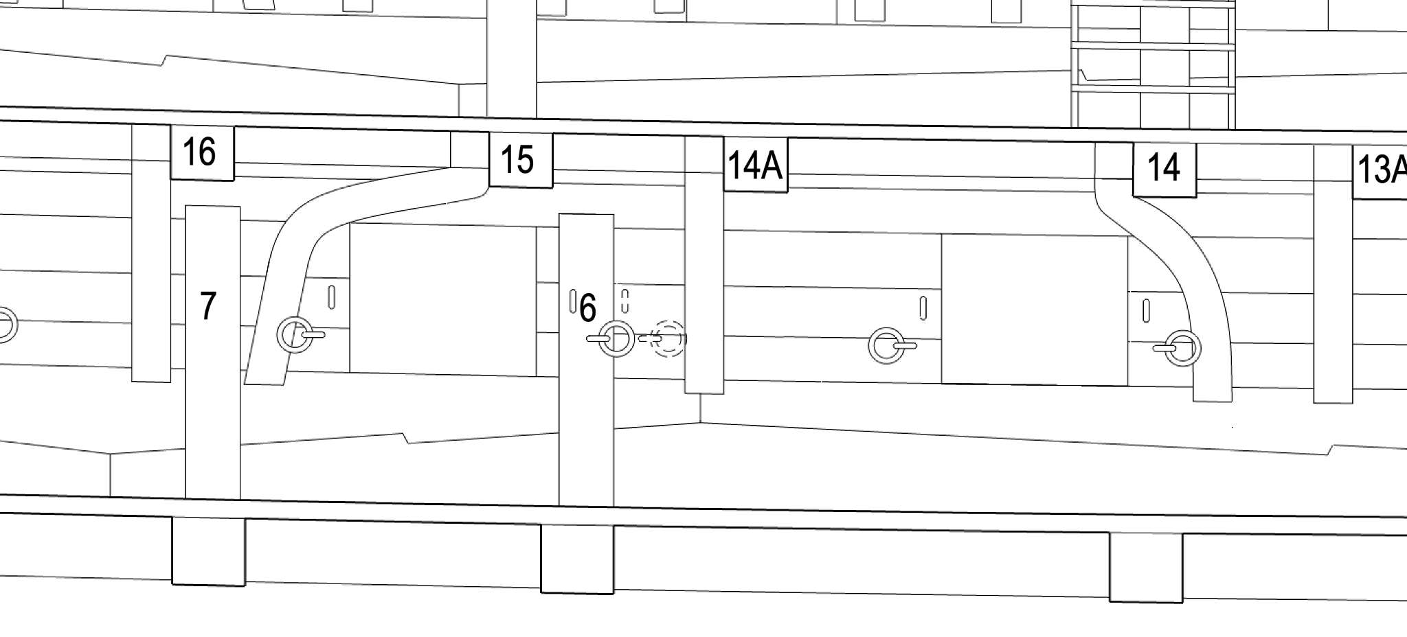
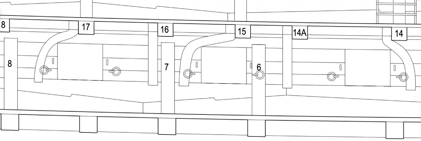
I just saw druxey's earlier note, wondering if a lodging knee does anything in this short space between 15 and 14A. It has virtually no longitudinal arm, so really isn't doing much in the way of lateral support. Maybe 14A is acting as a massive knee for 15. Food for thought.... I'll bet when the master shipwright was done laying out ports, beams, etc., he left it to the poor assistant shipwrights to figure out these little details, and to swear a little at the master shipwright not thinking this through more fully! Mark
-
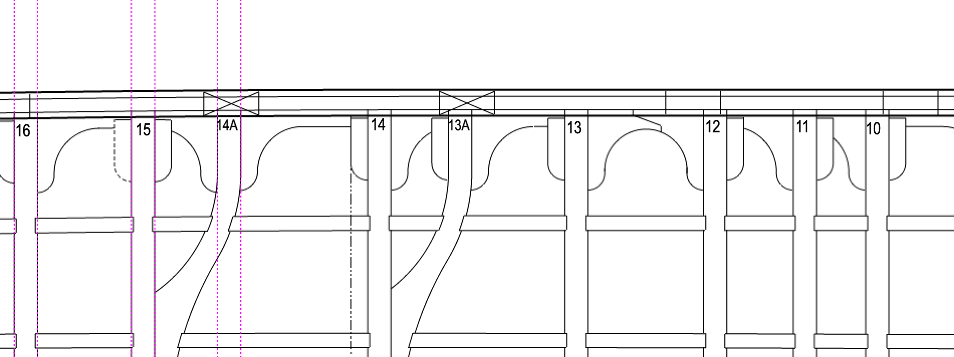
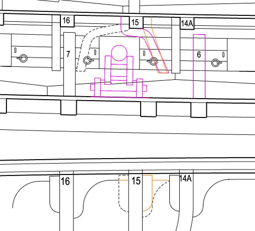
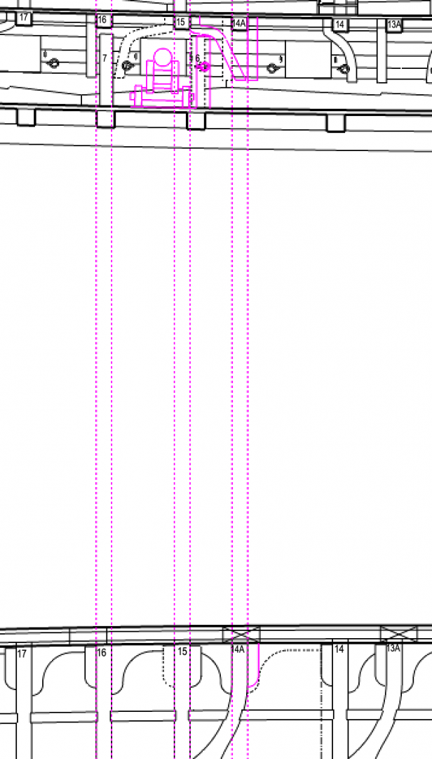
I am gluing in the quickwork, now stained red, but I have only 4 clamps that will work through the gunports, so this is a day of glue, wait, glue, wait... It gives me time between gluing to think more about the knee issue here. With Siggi's help, I moved standard #6 forward one beam, which cleaned up room for resolving the hanging knee on beam 15. It could: 1) run aft, as shown dotted; 2) or starting aft of the beam but running forward, as in the purple; 3) from forward of the beam as shown in orange. The orange option is the cleanest in section, but in plan it puts two hanging knees in the same space, leaving no room for a lodging knee. And beam 15 is especially important, anchoring the main mast partners and the bitts at the center. I would think it would want all possible lateral support in the way of a lodging knee. The purple and dotted option leave a lodging knee forward of beam 15, but would be some of the weirdest compass timbers ever grown. I think I will have to sleep on this choice.... Mark
-
Siggi, Ah, you are absolutely right! I did not draw the small curved beams in the gundeck on the section drawing. That changes my options a great deal, giving two more locations for standards. Maybe I can get the #6 standard away from the troublesome area. Thank you so much! I'll spend a little time rethinking what is going on in this area. It sure does help to have many people looking at these details, since I seem very able to miss things by mistake. Mark
-
beautiful craftsmanship! Mark
-
HI Gary, I just wrote some more thoughts about this over at my posting on the Bellona. I didn't want to mess up your site with a bunch of Bellona drawings. I discovered that there is a good reason for keeping the pattern consistent for the location of the hanging knees. That is because if you change back and forth at different points in the hull, you end up with a number of spaces between beams that have two hanging knees with no space for a lodging knee. I have seen only one example of this, in the drawing of the Arrogant of 1761, in Brian Lavery's book on the Bellona, page 46. But in this example, the spaces with two hanging knees are in places with little room for a lodging knee anyway. Mark
-
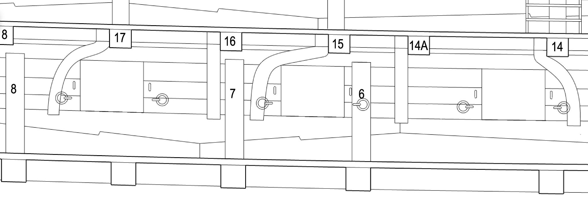
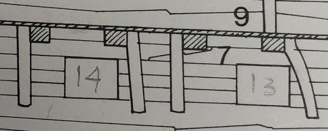
Thanks, Gary, your historical look does suggest this was an evolving idea in the shipwrights' world. the internal planking diagram of the Arrogant of 1761 (in the Lavery Bellona book, page 46) does show hanging knees on the upper deck bouncing back and forth between fore or aft of the beam, not necessarily related to the midships line of the hull. So your date of about 1760 seems right, as a time when things started to change. The difference in dates between your ship and mine may make a difference in how we handle this. Thanks, Siggi. My short curved beams are 14A and 13A in the section, which don't line up with a beam in the gundeck below, so I didn't see how there could be standards at those locations. I assumed that standards would always line up with a beam below, otherwise they would be pressing down on thin planking, not structure. But the contracts of the time call for 11 standards on the gundeck, which is fewer than the number of beams. So maybe I have the standards in the wrong places. I will have to look at that. In the cold light of morning, I see the knock-on effect of moving these knees around. My purple proposal below puts two hanging knees in the space between 14 and 14A, which leaves no room for a lodging knee. And a lodging knee seems particularly important here, taking some of the load of the short curved beam to the side of the hull. I can't find any examples of two HANGING knees in the same space in an important location like this. I have seen, and drew, two LODGING knees in a same space, which is how the pattern changes from fore to aft of center. See the locking lodging knees between 12 and 13 below. The only example I have seen of a space with two hanging knees and no lodging knee is in the internal planking diagram from the Arrogant of 1761, referenced above. But the several instances are in places with another beam very close by, with little room for a lodging knee. A lodging knee in these spots would not be nearly as important as the one between 14 and 14A above. So I think the quest continues on how to manage this particular intersection of knees and standards.... I sure am glad I am retired and can spend lots of time on fun problems like this!🙂 Mark
-
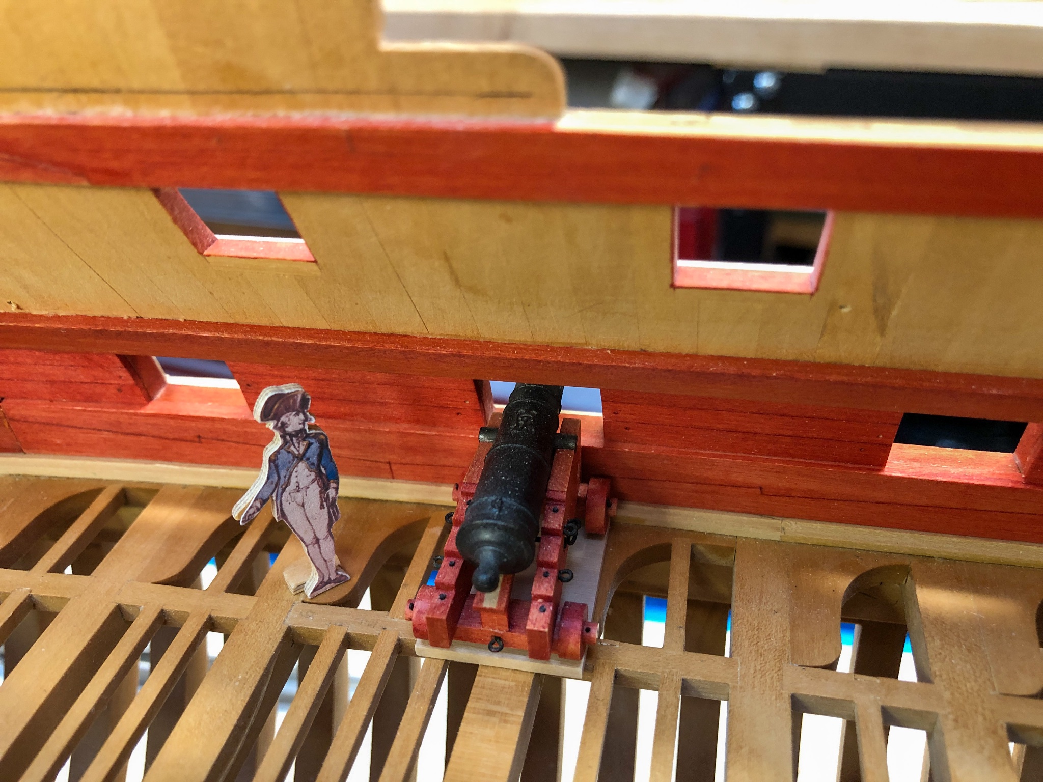
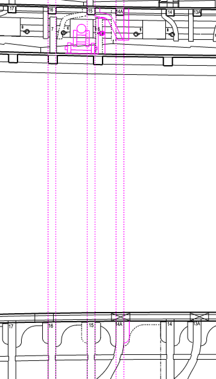
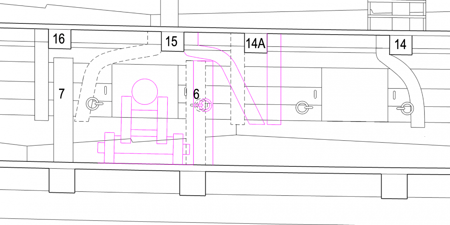
druxey, good suggestions. I drew the location of the gun carriage at the port to study this, and realized that the standard has to shift forward of the gundeck beam below it, to give enough clearance for the gun when it is run out. That then leaves room for the port tackle eyebolt to remain in its correct position, and the breeching ringbolt can move onto the face of the standard. And this only works if I shift the hanging knees at 14A and 15 to the fore sides of their respective beams. The dotted lines are my original idea, the purple lines are the proposed solution. Who says there are a lot of inter-relationships among the parts!☺️ Mark
-
Thanks, druxey, I I must have been posting my comments when your's came through. Yes, the only way the dotted line position makes sense if if there is a hull frame in that location. I will have to look at that more closely. Mark
-
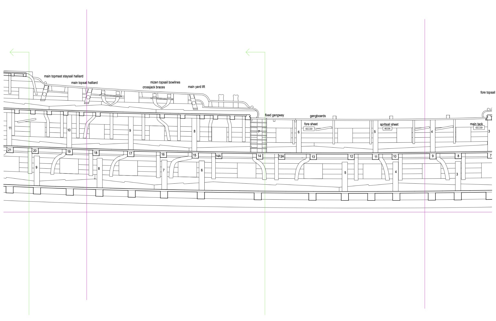
A little more drawing this morning, and I was able to clear the eyebolts and rings in all places but one, by casting the hanging knee a little further fore or aft of the port. The one remaining question is where standard #6 cannot move because it is related to the beam below. The ironwork either has to go on top of the standard, or moved fore of the standard as shown in the dotted line. Maybe the latter position is more consistent with everything else? Mark

-
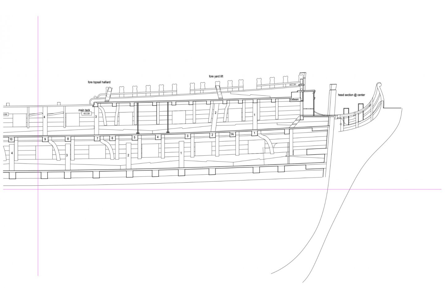
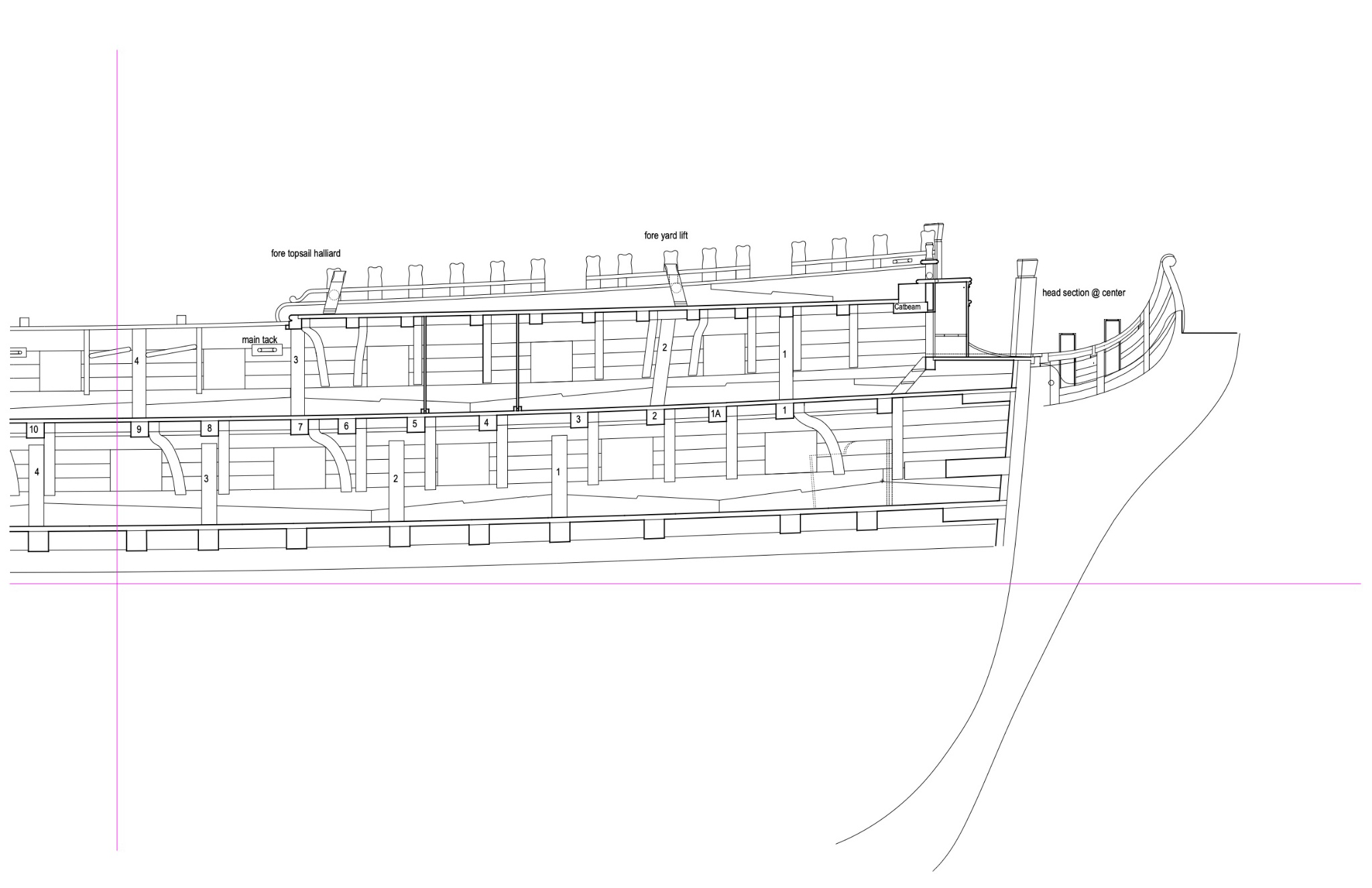
Thanks, Greg and Marc. Once I discovered the 18th century model builders did SWOPEM, it was an open door for me! But as you point out Greg, sometimes it was harder to do it in one piece than in many. The paradoxes of the world. I have finished cutting all of the quickwork, and realized that now I have each piece off the hull for staining, I could drill for the hardware for the gun tackles and breaching ropes. So I started laying out the locations for the eyebolts and rings, and discovered interference with the knees and sometimes the standards. Here is a sample. The rules for location I found in Allan Yedlinsky's great book, Scantlings of Royal Navy Ships; a note on page 151 locates the ironwork relative to the timber frame member adjacent to the port opening. The eyebolt for the port tackle is centered up and down on the port, 1/3 of the siding of the hull frame away from the port; and the eyebolt and ring for the breeching rope is a quarter of the height of the port above the sill, and 2/3 of the siding away from the port. This would ensure that the bolts run through a solid frame, and are offset in the same piece of wood to avoid splitting. But following this rule puts the ironwork sometimes right on top of knees or standards. I can see putting in compass timber knees where necessary to avoid the conflict, as I have done in a number of places below, but on the standard #6 in the second image, the conflict is not fixable. The standard is located by the beam below. So, would the eyebolts in this case have been shifted to the other side of the standard, or bolted through the face of the standard itself? Just when you think you have everything figured out....... Mark
-
Thanks so much, druxey and Gary. You keep me going through some tedious steps. I am working on quickwork now, which was not so quick when I started; but it gets faster with repetition until my brain wanders and I cut too short... Thanks also, Giampieroricci. The wood is all South American boxwood, and the red is a stain mixed in with the polyurethane finish. I can't stain up to a line because the stain travels through cells in the grain past the edge of the stain. That is why I have to stain first and install later. Mark
-
Hi Marc, I somehow lost the notifications to your build. I am just catching up. Looks spectacular! there needs to be a shanty song, "file, fit, file, fit, file, fit...."🙃 Mark
- 2,696 replies
-
- 4
-
-
- heller
- soleil royal
- (and 9 more)
-
Gary, I just remembered I was also looking at the inboard works drawing for the Arrogant, published in Lavery's Bellona AOS book, page 46. Have you seen the original? The way this is redrawn in the Lavery book leaves a lot of details unanswered. But it does show a few hanging knees aft of center on the forward side of the beam, for example, on the gundeck two ports forward of the stern, and another six ports forward of the stern. Mark
-
thanks so much, Gaetan, for the information about the camera and particularly the lights. Mark
-
Hi Gary, I just saw this string of posts on a very interesting question! I struggled to understand the conflicts between the drawings that you, Siggi, Mark and druxey refer to, and also the directions I saw in the 1763 Marlborough contract, which say, "Every Beam of the Quarterdeck before the Mizen Mast & Every other Beam abaft, to be kneed with 1 Hanging & 1 Lodging Knee at Each End." And for the Roundhouse, "Every other Beam..." Here is my best guess at how it works on the Bellona, whose ports do not align in the same way as the Dorsetshire, so I had to make "shipwright" best guesses at how to handle each location. I had to propose some pretty severely curved knees to make the rule work; I wonder if such trees exist! It also puts some knees in the captain's quarters, which are not compatible with panelling.... Mark