


wefalck
-
Posts
6,641 -
Joined
-
Last visited
Content Type
Profiles
Forums
Gallery
Events
Everything posted by wefalck
-
 Although Longridge's book has been written almost a hundred years ago, it still is a valuable source of information. He was able to draw on information before her preservation status and substance that has been lost in the fire a few years ago. The book also contains useful modelling hints and tips. The model he build is now in the Science Museum in London, but I don't know its actual whereabouts following the closure of their shipping department. I think anyone building a model of CUTTY SARK should have this book.
 -
Daniele, what is fixture with the ball-bearings for ? To guide the plank during milling ?
-
No screws in the hinges ? 😮 ... just joking. Nicely done. Have to face that at some distance in the future too.
-
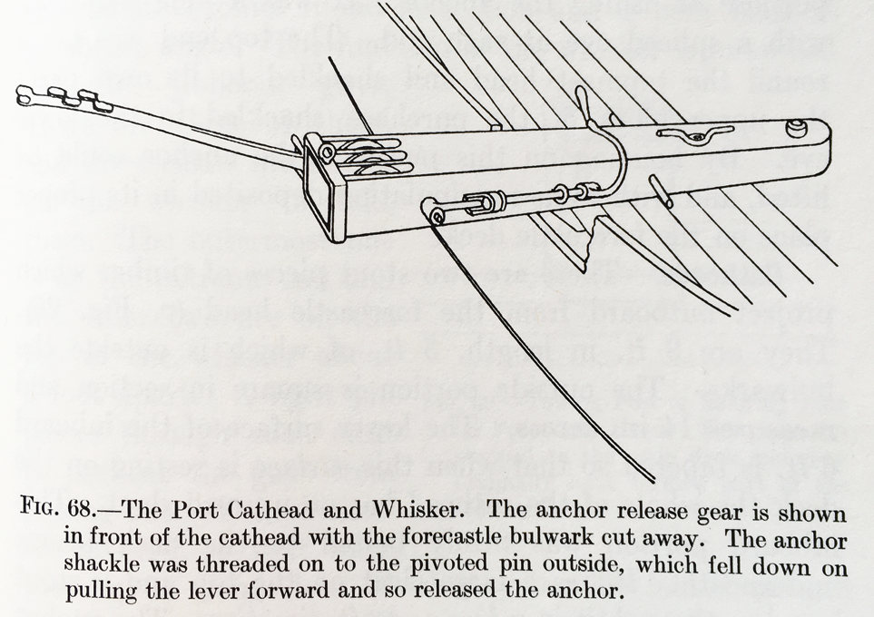
The release gear was not only used in an emergency, but any time the anchor was let go. The first step is to lower the bottom end of the anchor, so that it swings freely, suspended from the chain on the cat-head. That chain is shackled on one side to the cat-head and on the other side is put over a pivoting pin. How that works is best illustrated by a drawing in Longridges book; From: LONGRIDGE, C.N. (1933): The Cutty Sark.- 440 p., Kings Langley/Herts. (Model and Allied Publications, reprint 1975). In the above drawing the releasing lever is shown in the closed position. When it is pulled towards the viewer, the pin is free to rotate and the catting chain can slip off the pin. In the 1980s I took some pictures on board of CUTTY SARK and the mechanism looked exactly like that. Unfortunately, my slides are not accessible at the moment, so that I could not make a scan.
-
As always in life, there is never a simple answer to a simple question ? A laser-engraved deck cannot look really 'realistic' for a number of reasons: - the engraved line is likely to be too wide for technical reasons (but this depends on the scale of the model) - deck seems are filled-in with oakum and sealed with pitch because the deck planks expand and contract due to changes in humidity and temperature - when it is dry and cold, the seams are slightly depressed, when it is wet and warm, the seams slightly rise above the planks, because the latter expand - laser-cut decks are obviously cut from one sheet of (ply-)wood with one overall pattern of wood-grain, while in reality each plank has its own pattern; ideally the sheet would be cut from a wood with virtually no visible pattern of grain - ideally ... - the colour of each plank varies slightly, particularly, when not exessively holy-stoned. There would various strategies to make such deck look more 'realistic': - One could selectively stain each plank with very dilute stain in order to create this variability. - One could also first sand and seal such deck and then fill the engraved grooves with e.g. oil paint. After some drying time any excess oil paint can be scraped off; this would only work, when the engraved seams are not too wide. For any scale above 1:72 or so I would think that laying individual planks would be a more rewarding strategy. At smaller scales it may be still possible physically, but the wood grain may be too prominent, even after surface treatment.
-
Over the years I have come to dislike sawdust - seeing this slowly makes me reconsider ...
-
Photo Etching - do it yourself
wefalck replied to Dziadeczek's topic in Metal Work, Soldering and Metal Fittings
Thomas, I got into this from zero myself some 12 years ago, but stopped because of a house-move and other reasons. I had to figure it out the hard way with few suitable tutorials available at that time. On the other hand, I am a sort of chemist, so that side of the process did not challenge me too much and I understand what is happening (or not) and why. I think the key step for your success was to have the transparencies printed by professionals on high-resolution machines. It would be even better to go to a digital reprography company, where they expose repography films in a special camera, rather than melting toner onto the a transparent sheet. The repography process ensures 100% saturation and the resolution is probably an order of magnitude or more higher than even in professional laser-printers. I obtained my materials from a specialist supplier, including brass sheet already covered in photoresist. This takes out some key variables from the process, though cost more in terms of materials. But then the wastage may be less and it saves a lot of time. Still, I wasted a lot of material until I got all the parameters right, from the exposure times, to the concentrations of the solutions used, to the processing times, etc. Currently, I am actually rethinking the process, having acquired a small laser-cutter a few months ago. I will try to cover brass-sheet in black varnish and then burn the varnish away with the laser-cutter. This cuts out the step with preparing the masks. A technical problem to solve for double-sided etching is the poor zeroing behaviour of the cheap laser-cutter, which makes it difficult to achieve a good rapport when loading the second drawing into the cutter after flipping the sheet over. -
HMCSS Victoria 1855 by BANYAN - 1:72
wefalck replied to BANYAN's topic in - Build logs for subjects built 1851 - 1900
I think it always looks good, when those surfaces that are machined in the prototype are also machined in a model. They just look crisper. Yep, iron in cast-iron would have the tendency to rust fast. Bronze in cast-iron has a good relative coefficient of friction and is less likely to get stuck. BTW, adding the lanyards to the percussion-locks would be a detail not often seen- 1,013 replies
-
- 4
-

-
- gun dispatch vessel
- victoria
- (and 2 more)
-
Photo Etching - do it yourself
wefalck replied to Dziadeczek's topic in Metal Work, Soldering and Metal Fittings
I found that the only really critical step is making the masks, i.e. achieving a dense enough blackening. While this is not really a problem for people making circuit boards, it is a problem, when you want to push the technology to its physical limits, which is what we need to do in model building, at least for small-scale models. Neither laser-printed nor ink-jet-printed transparencies are really good enough. I also found that etching 0.1 mm brass or nickel-silver is not a problem, even up to 0.25 mm it works reasonably well, thicker sheets are difficult at least in trays. If you have cuvette with a percolator (air bubbling device), you may be able to push it a bit further. However, it is difficult to match the quality of professional foam- or spray-etched parts. One always battles with over- or under-etching in certain areas of the fret. However, I am talking here about exploring the technique in full, with surface-etching and having details as wide as the sheet-metal is thick. -
HMCSS Victoria 1855 by BANYAN - 1:72
wefalck replied to BANYAN's topic in - Build logs for subjects built 1851 - 1900
Pat, I think the elevating screws were probably of bronze, as the thread is cut into the cast-iron barrel lug. Somehow I had been thinking of the other version, where the barrel rests on top of the screw and there is a separate nut. Thinking 3D-printing further: one could actually print some holding fixtures to exactly match gun barrels to hold them e.g. in the lathe for machining say the bore.- 1,013 replies
-
- 4
-
-
- gun dispatch vessel
- victoria
- (and 2 more)
-
Sorry, I was on the wrong planet, somehow I did not read the first post carefully and was thinking of the fairleads for running rigging that are lashed to the shrouds ...
-
I would say, it depends on the scale. In most scales the lashing would be oversized anyway, so it is better to hide the ends, rather then using an oversize knot. On the real thing, I would suspect that it was finished with a couple of half-hitches around the shroud, but I actually don't know.
-
There is a lot of loose gear in a whaleboat and it may have to rowed for hours in a heavy sea. So it is a good idea to secure with lanyards those things that are vital to the purpose, namely the hunting gear. Securing the lances with a slip-knot to the boat might be useful.
-
HMCSS Victoria 1855 by BANYAN - 1:72
wefalck replied to BANYAN's topic in - Build logs for subjects built 1851 - 1900
I am very much impressed by those guns, Pat. They came out really nicely. It shows the potential of 3D-printing in all kinds of shipmodelling. You also did a good job in picking out in colour the details, such as the percussion lock. What also struck me immediately, was the 'real' elevating screw. Nice detail ! I gather it is 1 mm threaded brass rod or something like that ? Where they and the wing-nut made from bronze in reality ? Can you remind me, which 3D-printing technique you are using and what material ? Small-scale shipmodellers tend to make finished parts with with technique, while I am thinking of it more as a technique to reproduce parts that in the real world would have been cast in iron or bronze. The moulds would have been made from wood with complicated shapes that are not so easy to reproduce in small scale and even more difficult to reproduce, if you need several identical parts. Such parts then would still need finishing off on the lathe or mill, jut as for the prototype. However, the material used for filament-printing does not machine very well. One observation (if it is not too late): the axles seem to be rather long, the cotter pin should be very close to the truck, so close that it can spin freely, but does not move sideways on the axle. Not sure, I mentioned this before, but I tend to 'burnish' parts painted in metal paints with soft pencils. The graphite gives a metallic sheen to them. This could be good on the tyres of the trucks, but could also create even more plasticity on the lock.- 1,013 replies
-
- 5
-
-
- gun dispatch vessel
- victoria
- (and 2 more)
-
Epoxy over PVA
wefalck replied to dkuzminov's topic in Building, Framing, Planking and plating a ships hull and deck
Well, if the planks are too thin, this effect can occur as well, when they are bent across quickly changing radii. The best solution would be to fill the spaces between the bulkheads and then fair again the whole thing. -
Hydraulic Dredge by Steve Harvath
wefalck replied to Steve Harvath's topic in - Build logs for subjects built 1851 - 1900
Run a soft pencil (B6-B8) between the teeth of the gear, it will make the silver paint look more like metal ! -
Epoxy over PVA
wefalck replied to dkuzminov's topic in Building, Framing, Planking and plating a ships hull and deck
Looking at your bulkheads, it appears that the real problems is, that they have not been faired. I can see the discolouring from the laser-cutting across their whole width. Of course, the planks will make kinks and buckle then, when bent across the sharp edge of the bulkhead. -
The loop around the wrist is for the lance, not the harpoon, of course ! The harpoon is let let go after placing it into the whale, the line runs out from the tub controlled by the post in the thwart in front of the harpooneer, who keeps it tight by holding it with a pair of 'nippers' to protect his hands, while it is running out. It is also cooled down by dowsing it with seawater. The line is then slowly heaved in by the crew, when the whale resurfaces to take a breath - a process that is repeated until the whale is so weakened that it can be approached to kill it with the lances.
-
Epoxy over PVA
wefalck replied to dkuzminov's topic in Building, Framing, Planking and plating a ships hull and deck
Sounds a bit strange. Perhaps you want to post a couple of pictures ? -
I gather the 'bible' at leas on US American whaleboats is ANSEL, W.D. (1983): The Whaleboat.- 147 p., Mystic, Co. (Mystic Seaport Museum Inc.). I quickly leafed through the illustrations in my copy to see, whether any enlightenment could be found. According to Ansel the notch for straigthening irons would be cut close to the bow on the port side (for the boat of a right-handed harpooneer). Ansel does not mention the 'tails' in the drawings. By their length and the fact that they are drawn in your plan in association with the forward thwart, I would think that these are lanyards with which the spare iron were secured to the boat. That is, if they are really 12" long. If it reads as 12', however, then these could be spare lanyards attached to the lances and the harpoons - they were attached to the iron, went along the wooden shaft with several half-hitches in between and ended in a spliced eye to fit around the wrist of the harpooneer.
-
Sorry, but the picture is sideways and too small to be really readable ...
-
Sorry, but it is not clear what you are referring to. Perhaps you could post a detail picture of the part in question ?
-
Epoxy over PVA
wefalck replied to dkuzminov's topic in Building, Framing, Planking and plating a ships hull and deck
'Micro-balloons' (https://en.wikipedia.org/wiki/Glass_microsphere) are the standard filling material for epoxy and other resins. If the model is going to be a stationary one, not exposed to water, the stiffening effect could be probably achieved without having to mess around with epoxy by just liberally painting on PVA glue. However, the more common procedure would be to use filler blocks, normally inserted between the bulkheads before the planking is applied. If you use styrofoam or other hard foam, this could be done easily retrospectively, again using PVA rather than some messy two-component resin (which would not be compatible with styrofoam anyway). -
Anyone ever seen crosstrees formed in nitrocellulose?
wefalck replied to Sparkysparks's topic in Masting, rigging and sails
Auf course, in most countries around the world, with a few sad exceptions, the trade in endangered species or products made from them is prohibited. I think you can bring into the country for personal use such items, when you can show that they are antiques and that you, say, inherited them - thinking, for instance of combs, boxes, frames for glasses, etc. The said degradation does not seem to affect too much coloured and 'filled' items of celluloid. We have in our family dolls and some household items made almost a hundred years ago and they are still in good order.