wefalck
-
Posts
6,651 -
Joined
-
Last visited
Content Type
Profiles
Forums
Gallery
Events
Everything posted by wefalck
-
 0.8 mm square copper wire indeed seems to be the smallest square wire commercially available. A short while ago I was able to buy a miniature jewellery rolling mill. It is actually meant for enlarging wedding rings and such, but I will convert it for rolling (soft) round wire into tiny square, rectangular or half-round wire. CuNi-wire is available in a wide variety of dimensions as flat wire - it is being used in heating elements. A while ago I got a good selection of old stock from ebay.
 -
Personally, I would have turned this from the solid, with apropriately thinned out edges ...
-
Thanks again, gentlemen, for your praise ! @Keith Black: A Preiser set of unpainted figures, in N-scale, will be the starting point for making the crew. Lots of carving, sculpting and micro-surgery, I expect. @shipmodel: I had been toying with the idea of using such monofilament, but I don't like its sort of light translucency (which would require painting) and I am not sure, whether simulating chain by double-twisting the material would work with this material. Perhaps I should give it a try with thermosetting the twists with my hot-air gun.
-
For those shields you could use a segment of a ring of paper, sheet-metal or styrene. It’s the surface of a truncated cone and you will have to calculate the necessary radii.
-
… those to the uninitiated rather unspectacular details consume indeed a lot of time 👍
-
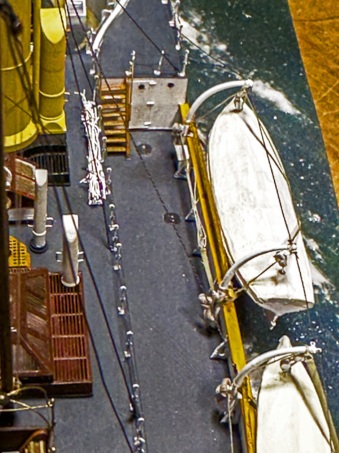
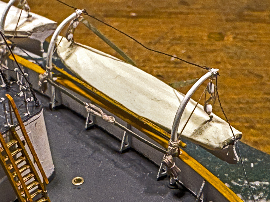
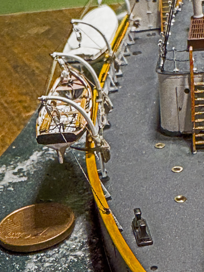
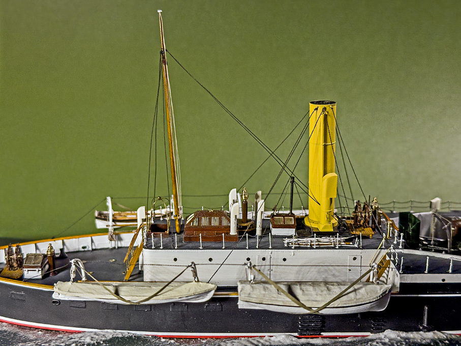
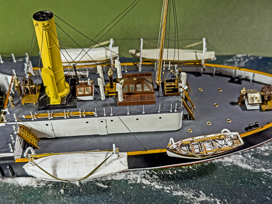
Thank you very much, gentlemen, for your appreciation ! ********************************************************** Installing the ship’s boats 3 The installation was movd further to completion by tidying up the loose ends and producing the bunts for runners of the boat tackles. The runners are about five times the distance between the head of the davits and the waterline long, plus some extra for handling. However, as the rope is slightly overscale the runners were cut a bit on the short side in order to make the bunts not too bulky. The actual runners were cut above the cleats and the bunts were formed over two clothes pins driven into a piece of wood and have a loop pulled out with which they can be hung over their respective cleat. Note that the runners for the ‘ready’ boat are not arranged in bunts but in coils, ready to be thrown loose so as to allow the boat being lowered quickly e.g. in a case of man-over-board. Again, working from the inside out, the next items to go on were the stays for the davits. Luckily, the stays are drawn in the lithographs so that their points of fixation are known. I had to deviate a bit from those drawings, as they pertain to the longer, turning davits for the boats stored on rack, which belong to a slightly later period. The stays are supposed to keep the davits aligned, rather than helping to swing them around. It was a bit of a trial-and-error procedure, before I came up with a protocol for making miniature fake chains of exactly the right length and with loops at both ends. The chains would have been shackled into ring-bolts at the head of the davit. No way of making shackles in this scale, so I just tied the fake chains to ring-bolts with fly-tying thread. Some people may think now that’s it, but in fact there still is quite a long to-do list for little details: - davit for the stern-anchor - flag-poles and flags - for the gun: tampon, wiper, rammer, and two gun-sights - and the … crew! To be continued ....
- 935 replies
-
- 25
-

-

-
Chopper Lesson Learned
wefalck replied to Todd Hart's topic in Modeling tools and Workshop Equipment
... but this thing is just a miniaturised mitre-saw, not a 'chopper', i.e. there is a saw-blade with teeth. From an engineering perspective, this thing is not a terribly intelligent design, as it lacks a proper adjustable guidance for the saw-blade. If anything, there should be a gib-strip to control the clearance with which the saw moves. -
On a real ship the waterline may have looked really awfu, hand-applied bottom paint just by eye ... I gather for many ships a good approximation would be that the bottom paint goes up to below the wales (as Roger already pointed out) at it's deepest point. From there it would follow a horizontal line forward and backward to the stem and stern respectively. Well not exactly: in most cases the waterline was given a slight(!) curve upward towards the stem and stern. This has two psychological/aesthetic reasons: for one the hull looks more dynamic and the ship faster in that way and then, particularly larger wooden ships tend to 'hog' with time, meaning that the ends begin to hang down, because of the stresses on the hull in the sea; an upward curve of the painted 'waterline' compensates for this.
-
Chopper Lesson Learned
wefalck replied to Todd Hart's topic in Modeling tools and Workshop Equipment
It all depends on the 'chopper' you have. When I was a student, during vacations I worked in a DIY store and one of my tasks was to cut picture frames to order. The foot-operated 'chopper' would cut mitre notches for frames as much as 50 mm thick ... -
Rigging Cutter Square Sail Sheets and Tack
wefalck replied to Thukydides's topic in Masting, rigging and sails
Just out of curiosity: why would there be yard to which only the foot of the top-sail is attached and then above it another yard for the square fore-sail? It seems to be a rather strange arrangement with on first view no practical advantage ... -
I think actually, that much what could be (only) achieved with galvanoplastics in the past, can be achieved today with 3D-printing. The complex shape of the exhaust-manifolds can be modelled and then printed on a 3D-printer. However, the then to-scale-thickness of the end-tubes is difficult to achieve in anything but metal. If it was me, I would design the 3D-printed manifolds for inserting short pieces of metal tubing, because in photocured resin, the end-tubes would be still too thick-walled and very fragile.
-
There was/is a Russian/Ukrainian (I don't remember which ...) colleague on this forum, who made galvanoplastic ventilators and similar hollow parts. I also know of railway modellers, who 'grow' rivets on metal with this technique. In galvanoplastic, you make a wax core, cover it in a silver paint to make it electrically conducting and then galvanically deposit copper on it. The way then is melted out. It was once a very common method to reproduce medals, small objects and even architectural decorative items (in the latter case using zinc). Basically, if you are set up to do your own photoetched parts, you could also do galvanoplastics.
-
Well, 'invisibility' is a matter of viewing distance. It's the conundrum of us modellers that we have to cater for different viewing distances, unless we can force the viewing distance by building a true 'diorama' (in which case also the viewing angle is fixed) or by putting the model/scenic arrangement into a glass-case which gives a minimum viewing distance. My 'rule' is that I try to represent everything that can be physically represented within the limits of materials and tools (and my own dexterity). As one series of travel-guides put it: "you only see, what you know" - of course, if you don't know anything about ships and how they were constructed/operated, you would not miss details, but if you know that is was there, you will miss the detail and if it is only a trivial detail, such as nail or dowel patterns. BTW, I really like this ramshackle and improvised appearance of those buildings. I alwways found it strange, that in the USA there is so much more photographic evidence of such buildings compared to Europe. Perhaps photography was much more frequently practiced in those early years of its development in the USA then in Europe. Or our numerous wars have wiped out such buildings and necessitated rebuilding. Or we tended to build more in stone than in wood.
-
Sleek indeed 👌🏻
-
Did 18th and 19th century ships have flat weatherdecks?
wefalck replied to Rushdie's topic in Nautical/Naval History
I don't know the kit, but perhaps one can sand a slight camber into the deck-planking? You would have to check, how this works out with the water-ways etc. -
I just checked the data given by MIDDENDORF, F.L. (1903): Bemastung und Takelung der Schiffe.- 401 p., Kassel (reprint 1977 by Horst Hamecher). which, albeit in German, is probably the most detailed textbook with relevance to the late 19th century. He designed and rigged inter alia the five-masted ship PREUSSEN. On page 313 there is table for jack-stays and their fittings. The diameter of the jack-stay is proportional to the length of the yard. For a 10 m yard the diameter should be 15 mm and its centre above the yard 25 mm. For a 30 m yard the diameter should be 25 mm and the centre above the yard 36 mm.
-
Did 18th and 19th century ships have flat weatherdecks?
wefalck replied to Rushdie's topic in Nautical/Naval History
I gather the answer is, as often, yes and no ... camber seems to have been also subject to fashion. It seems to have become gradually flatter over the years, but was always there in wooden ships. For iron- and steel-ships the situation is a bit different and also a question, whether they had wooden decking or metal decking. Wooden decks always had a camber and usually metal gutters or water-ways to take water away from the edges of the wood. Metal decks can be essentially flat. From a constructive point of view, the camber not only serves to shed water (which, btw is only really relevant, when the ship sit upright in the water and doesn't move much), but also to predetermine in which way the beams will deform when under stress. A curved deck-beam will always bulge up, when under compression in the sea, while a straight beam could do it either way and in different ways from bow to stern. Such movement could lead to a leaking deck, as the planking would be stressed much more. -
SMS Karlsruhe by Wreck1919 - 1/100
wefalck replied to Wreck1919's topic in - Build logs for subjects built 1901 - Present Day
I gather the fact that the stirrups are slightly curved seems to indicate that they were made from wire rope. You can slightly soak stirrups and footropes in fast drying varnish and hold them in shape, while the varnish dries. Use solvent-based varnish, so that you can soften the arrangement, if you are not happy with it at the first go. -
Ladies' pads make great emergency bandages ... don't ask how I know this 🫢
- 174 replies
-
- 6
-

-
-
- Vigilance
- Sailing Trawler
- (and 1 more)
-
As I said, I really liked your rendering and 'weathering', it was just a thought that came to my mind. In shipmodelling there seem to be two 'schools', the one aims to show their skills in wood- and metal-working, resulting in what I would call 'artisanal' models. At the other end of the scale there are those, who aim to produce 'realistic' models. The latter seem to be mostly plastic kit-builders working in small scales and producing water-line models. Water-line models in this category make sense, as they show the ship in its real environment, rather than high and dry on a pedestal. I think it is mentally easier to make a model looking scruffy that was build from a kit, than one built from scratch, where one spend a lot of effort to machine the parts as well as possible.
-
Excellent painting and ageing/wearing job on the leather and floor-boards 👍🏻👍🏻 One thing though bugged me: did these machines really become old enough to experience such wear and tear?
-
I have been using Vallejo acrylics for years. Their shine depends on how they are applied, with a brush or with an airbrush. Airbrush application gives matt or satin surfaces. For a high gloss of varnish it needs to be applied by brush or very wet by airbrush - with the risk of 'runners'. Acrylic paints are a mixture of emulsion and suspension (while oil paints are suspensions). Emulsions are very delicate and the wrong thinner or mixing them with other brands can lead to a break-down of the emulsion, i.e. coagulation or clotting. Pure acrylic emulsions are glossy when cured. Matt or satin varnishes or paints are achieved by adding various quantities of finely dispersed pumice or diamtomee earth. Adding pigment to give a paint in itself acts like a matting agent, which is one reason, why most acrylic paints are satin at most. Acrylic paints and varnishes cross-link quickly, which is why they dry fast. However, this process traps some water in the structure, which then can take days or weeks to diffuse out and evaporate. At the same time the cross-linking continues to intensify. For this reason, acrylics stay sort of rubbery for a long time. Depending on the formulation, they never will be as hard as fully oxidised paint based on lineseed-oil. For this reason, the classical method discussed above, of rubbing down oil-paint with pumice and then re-buff it to the desired sheen does not really work, at least not with the Vallejo-paints. There acrylic paint formulations for industrial applications, such as painting machine tools, that will be as hard as oil paints. Rather than mixing something into your black paint, I would experiment with different mixing ratios of gloss and satin Vallejo acrylic varnish (I would use the pre-diluted Model Air range for this) until you get the sheen you want with your chosen application methods, i.e. brush or airbrush.
-
Blades for Artesania Latina Cutter
wefalck replied to brunnels's topic in Modeling tools and Workshop Equipment
Why would one cut 4 mm x 4 mm wood with a gouillotine and not properly with a saw? There are probably several factors that led to the blade failure in these application: too thin blade, blade sticking out too far, and not stiff enough tool. All these are inherent in the tool, which probably wasn't designed for such an application. If you'd use a stronger/thicker blade, something else will break or wear quickly. -
That's the problem with those sets - when we were kids, there were only blocks. I remember that I got Lego wheels from everyone for my 6th birthday, as they just had come onto the market ...
-
SMS Karlsruhe by Wreck1919 - 1/100
wefalck replied to Wreck1919's topic in - Build logs for subjects built 1901 - Present Day
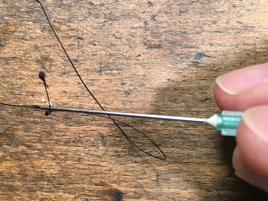
Just get rid of the brass rings, they have nothing to do there, sorry. If you use 'rope' rather than wire, you can stiffen the rope with thinned shellac solution or zapon-varnish. Hold them the way you want them, while the varnish is drying. Making eye-splices in thread is easy with the help of a hypodermic needle as marlin-spike: