


wefalck
-
Posts
6,665 -
Joined
-
Last visited
Content Type
Profiles
Forums
Gallery
Events
Everything posted by wefalck
-
 He could also use the laser-cutter to engrave those slots ...
 -
There is also a five-language edition, but I don't know, whether there is any digital copy somewhere on the Internet: PAASCH, H., CHALLAMEL, P., MATTHIESEN, F.E., BUDDE, A., MONTOJO, P., ROMAIRONE, G. (1908) From Keel to Truck – Marine-Wörterbuch Englisch-Französisch-Deutsch-Spanisch-Italienisch.- 1110 p., 109 pl., Hamburg (Eckhardt und Messtorff).
-
Coming on nicely ! Concerning the rails: - I think, if you cut a half-round seat for the handrail into the uprights using a burr and then use solder-paste that should work. - likewise for styrene rods, a half-round seat in the uprights and other joints locates the parts and requires less cement - I would use styrene cement, which welds the parts together, rather then glues them.
-
Ah, it's the 'Bobrik'. Here is a bibliography of this important mid-19th century German author of a very comprehensive maritime encyclopedia: E BOBRIK, E. (1846) Handbuch der praktischen Seefahrtskunde, Bd. I, enthaltend allgemeine Vorbereitungen zur Steuermanns- und Schifferkunde.- 1-816, Zürich/Hamburg (Julius Fröbel & Co./Hoffman & Campe). E BOBRIK, E. (1846) Handbuch der praktischen Seefahrtskunde, Bd. 2-1, enthaltend geographische und astronomische Steuermannskunde.- 817-1808, Zürich/Hamburg (Julius Fröbel & Co./Hoffman & Campe). E BOBRIK, E. (1846): Handbuch der praktischen Seefahrtskunde, Bd. 3, enthaltend logarithmische, geographische und astronomische Tabellen; Tafeln zur Schifferkunde; geometrische Zeichnungen, Abbildungen und Karten.- Tafeln (nicht ausgefaltet!), Zürich/Hamburg (Julius Fröbel & Co./Hoffman & Campe). E BOBRIK, E. (1848): Handbuch der praktischen Seefahrtskunde, Bd. 2-2, enthaltend Schifferkunde.- 1809-2688, Leipzig (Verlagsbureau). B BOBRIK, E. (1848): Handbuch der praktischen Seefahrtskunde, Bd. I.- 816 p., Leipzig (Verlagsbureau). B BOBRIK, E. (1848): Handbuch der praktischen Seefahrtskunde, Bd. II, I. Abtheilung.- 992 p., Leipzig (Verlagsbureau). E BOBRIK, E. (1848): Handbuch der praktischen Seefahrtskunde. Bd. II, II Abtheilung: Stereometrie ; Statik und Hydrostatik; Dynamik und Hydrodynamik; Schiffgebäudekunde; Zurüstungskunde; Manövrierkunde; Ankerkunde.- X+858 p., Leipzig (Verlagsbureau). B BOBRIK, E. (1848): Handbuch der praktischen Seefahrtskunde, Schiffgebäudekunde, Zurüstungskunde, Manövrierkunde, Ankerkunde, Tafeln zur Schifferkunde.- 604 p. + Tafelband, Leipzig (Nachdruck 1978 bei Horst Hamecher, Kassel). B BOBRIK, E. (1848): Vom Tauwerk und seiner Zubereitung zur Taakelasche (aus Handbuch der praktischen Seefahrtskunde.- 24 p., Leipzig (Nachdruck 1975 bei Verlag Egon Heinemann, Norderstedt). E BOBRIK, E. (1858): Allgemeines Nautisches Wörterbuch mit Sacherklärungen: Deutsch, Englisch, Französich, Spanisch, Portugiesisch, Italienisch, Schwedisch, Dänisch, Holländisch.- 752 p., Leipzig (Robert Hoffmann). An E in front of the title means that you can find a digital version on the Internet.
-
It's a universal motor and these starting capacitors don't live for ever. Should be easy to replace and the motor will be back to life. Check also the brushes, of course.
-
To be honest, I wouldn't worry unless you want to drill holes below say 0.3 mm diameter. The machine is probably adequate. If you happen to have a dial-indicator, you can chuck up a drill and check ...
-
It's not only about play. There are two key points that determine the 'run-out' of a drill taken into a chuck or collet: - how concentric is it held with respect to the rotational axis of the spindle, and - how parallel is it held with respect to the rotational axis of the spindle If the drill was perfectly parallel, but not concentric, it would rotate in an imaginary cylinder around the spindle axis. If the drill was not parallel, then it would rotate in imaginary cone around the spindle axis. In both case the drill tip moves around in a circle, which causes sideway stresses on the drill, results in holes larger than the drill-size and can lead to breakage of the drill (particularly when using the fragile carbide drills). So the chuck can sit tight on the spindle and the drill tight in the chuck, but you still have the above phenomena.
-
Depends on how much you are prepared to pay for it an how well the connection between the spindle and the chuck is machined. If you pay several hundred EUR/USD/GBP for an Albrecht-chuck that has a taper at the end that in turn fits into a concentrically machined female taper in the spindle, you get the least run-out off any chuck you can think of. Jacobs-chucks inherently have a bigger run-out than collets. So whenever possible one should use collets. For instance the PROXXON-drills have a collet-seat machined into their spindles, so you have the option of either using a chuck that screws onto the spindle or the collets. I don't know what the spindles on these drills look like that started the discussion. Perhaps they are already have a female taper for ER collets? If not, perhaps one can replace the spindle with a commercial one that has the right taper - they are cheap and can be bought in different diameters from ebay et al. For such a machine, ER11 collets would be sufficient. They can take drills of up to 7 mm diameter. As always, you get the precision you pay for ...
-
Agreed, very well done! Why was the chain on port doubled? I could imagine that it has to do with a mechanism to adjust the rudder midship and to tighten up the chain, but cannot work out its function ...
-
Thanks for the pictures and measurements - it seems that the small one is not available separately, but I have to continue looking. I recently bought some heat-activated silkspan-tape that I want to use for making sails and for this these shoes would be just the right thing, plus the 6 mm-stem fits into my soldering iron.
-
Nice tour de force across some machining and alignment problems ! I have had the same vice for decades and due to its lack of accuracy relegated it really coarse work only a long time ago. I am now using so-called toolmaker insert vices instead. They are available down to 20 mm jaw width and cost around 40 EURO/USD/GBP only. The more parts the greater the chance of accumulating manufacturing and alignment issues. Such sine-type tables are nice, but as you experienced need to be manufactured to close tolerances on all parts in order to ensure overall accuracy. For my little toolmakers vice, I went a different route and made a tilting device from a solid piece of aluminium that has no moving parts per se and only two critical dimensions: the verticality of the sides of the slot into which the vice fits and the parallel alignment of the holes for the fixing bolt vs. the bottom surface. Both dimensions I could control reasonably well with my equipment:

-
Long term CA vapors
wefalck replied to ricky86's topic in Building, Framing, Planking and plating a ships hull and deck
Something I learned as a teenager from my father, who was a chemist working with acrylics in the pharmaceutical industry, is that CA needs humity to trigger polymerisation - therefore one should gently breathe on the are to cemented together and onto the CA applied. Indeed, a big blob of CA will quickly polymerise on the outside, but that forms a shell into which humidity cannot penetrate to support polymerisation. Hence, it may take a while for such a blob to fully cure. -
Long term CA vapors
wefalck replied to ricky86's topic in Building, Framing, Planking and plating a ships hull and deck
In theory, once polymerised, which takes a few seconds, there should be no fumes. The best way to avoid issues with CA is to not use it on things for which other glues/cements are available -
Just a quick question, Gary, concerning this little quilting iron by Clover, which intrigued me. It seems not so easy to get over here in Europe. The question: what is the diameter of the stem of those shoes that slip into the heating element? I was thinking of getting just the shoe and use in my temperature regulated soldering iron. And yes, I also like the jig for bending planks over the edge - simple, no fuss and practical !
-
Absolutely !
-
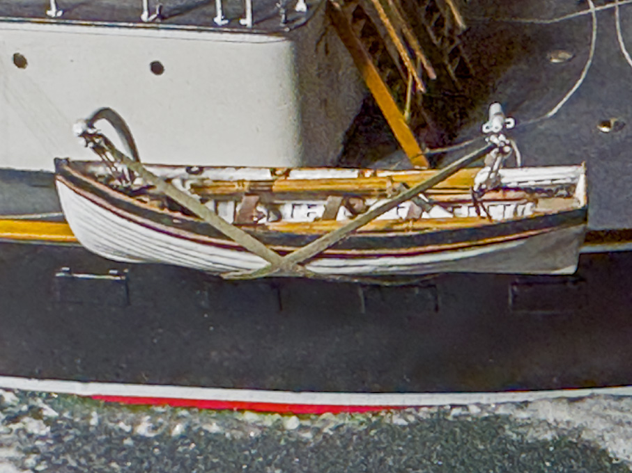
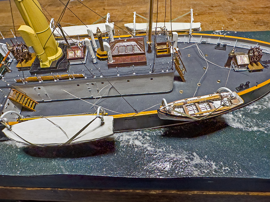
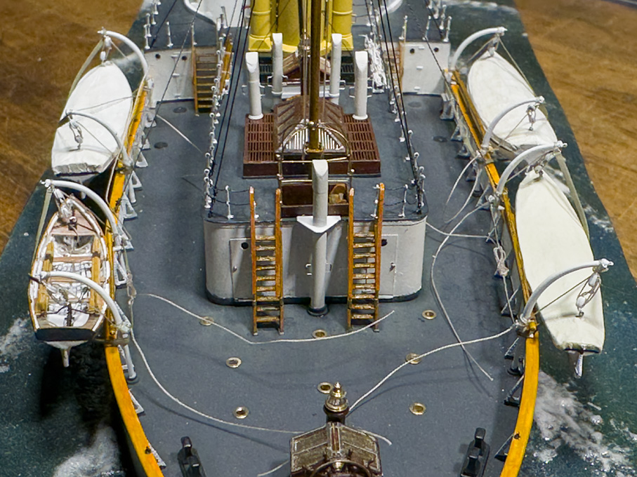
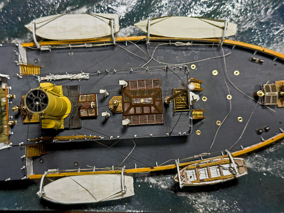
Thanks, Ab, much appreciated ! ********************************* Installing the ship’s boats 2 It is done! All four boats are suspended from their davits and the work was achieved without major damage to other parts. Good thing that there is not (yet) any brain recorder … because of the mental language that accompanied the process at certain stages. Still there is a lot to be done, such as tidying up the loose ends, making and installing the coils of rope from the runners of the boat-tackles and the longitudinal chain-stays for the davits. To be continued ....
- 935 replies
-
- 24
-

-

-
Sage advice. Acrylic paints are carefully balanced emulsions and the wrong additives can make them break down.
-
Pulled the Trigger == Lathe coming
wefalck replied to kgstakes's topic in Modeling tools and Workshop Equipment
Well, I would rather first get a bit of experience in turning, as the quality of all your parts depends rather on the precision with which you have turned down the jaws. You would need a round piece of very good quality, such a ground piece of tool-steel. Onto this you tighten the jaws and then you can turn the outside of the jaws. However, you just end up with a set of stepped soft jaws. If it was me, I would get myself one of those self-centring chucks from Sherline - I think they do them with the right thread for the Taig, but I am not sure. I have several of those Sherline chucks and they are perfectly adequate for our kind of work. Having said that, I find that I rarely use the 3-jaw-chucks for modelling work, they are mainly used for tool-making. Whenever possible, I use collets. much safer to work with. -
What kind, brand and where do you buy your end mills?
wefalck replied to rlb's topic in Modeling tools and Workshop Equipment
Yep, a milling machine can be used for turning as well. For amateurs, military field-use or on board of small ships in history, combination machines were developed (see www.lathes.co.uk) that could do turning, boring, and milling with little or no change of set-up. With modern CNC-machines the distinction between these operations also has faded away, as the work-piece would be chucked onto driven axes and then driven or stationary tools applied. Another example for this 'relativity' is that lathe boring-bars can be used in a boring-head on a milling-machine ... For the moment I am well kitted-out, but I used to be always on the look-out on ebay for lots of such carbide tools discarded by industry. There are small traders who buy them off industrial companies in bulk and then sell them in amateur-sized lots. You may get good cutters for less than 1 EUR/USD/GBP per piece. OK, wood can dull cutters quickly, but they usually lasted me for years. -
Roger, not sure that your conclusions are all correct. There was intermediate period in iron- and armoured-ship development, when they reverted back to composite construction. There were two reasons: one was that in experiments (these are e.g. documented for France in the Aide mémoire de l’artillerie naval 1873ff) it was found that when armour plates were attached directly to the ships structures, the impact of projectiles weakend these structures; a wooden backing provided a sort of resilient buffer that distributed the stresses. On the other hand, iron hulls fouled fast and it wasn't until 1860 that the Bremen captain Rathjen developed the classical red-oxide coloured anti-fouling paint that contained arsenic and mercury compounds. In the late 1860s already other colours became available. Nevertheless many navies around the world relied on copper- or Munth-metal-sheathing well into the 1890s. For reasons of galvanic corrosion, these could not be attached directly to iron plating, so that iron hulls were first sheathed in wood, onto which the copper or Muntz-metal was applied. I am not aware that zinc sheathing was used on iron ships. I think it would have been eaten away very quickly by galvanic corrosion, if there were any metal parts on the ship exposed to the water. After all, this is way today we put sacrifical zinc anodes onto our ships. The French sources are quite good and one should e.g. scan the Atlas du Genie Maritime etc. for cross-section of hulls of ships of this time in order to see how they were constructed. A wooden ship stationed in China almost certainly would have to be metal-sheathed, as much of the Chinese waters are sub-tropical. Note: I wrote this while Shipific posted his response. You may also want to have look at my images of builders' models of ships of that period in the museum in Paris: https://www.maritima-et-mechanika.org/maritime/paris/frenchironclads.html
-
What kind, brand and where do you buy your end mills?
wefalck replied to rlb's topic in Modeling tools and Workshop Equipment
This is now a bit of thread-drift, but coming back to those down-cut carbide cutters: I got them by accident among a bunch of up-cut ones in a lot - some production industries (circuit-board manufacturers, aerospace, etc.) change their cutting tools regularly in order to avoid spoiled parts and unscheduled down-times. Such tools are still good enough for our puposes because they have been changed before they become dull. Such lots appear frequently on ebay. The shank diametres are usually imperial, i.e. 1/4", 3/16", and 1/8". The best use in my workshop for the down-cut ones is as very stiff boring-bars on the lathe, preferably in through-holes. They work on any kind of material a shipmodeller is likely to encounter. They would also work for side-milling or milling of rabbets or basically anything, where the chips can be thrown out sideways easily. However, the up-cut bits are much more versatile in any case and I would only look for them. -
What kind, brand and where do you buy your end mills?
wefalck replied to rlb's topic in Modeling tools and Workshop Equipment
Unlike toolmaker it seems, I am a mere self-taught amateur ... -
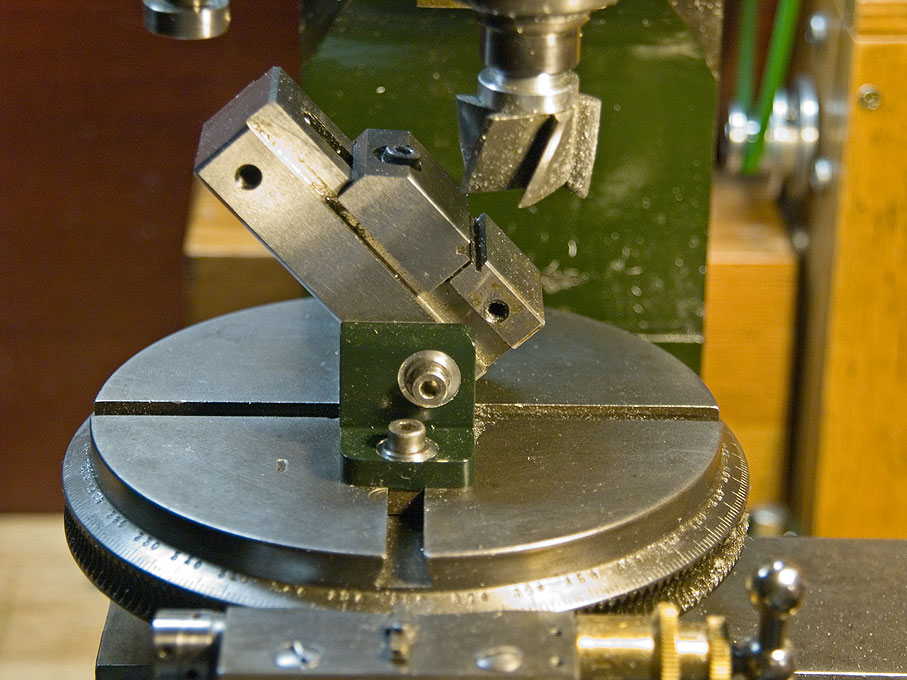
Well, when you tighten a vice the loose jaw often has the tendency to lift or when the guides of the loose jaw have too much play, the jaw can move sideways when tightened. Both the fixed and loose jaw should also close tight and precisely when tightened without a workpiece in it. Finally, the edge of the fixed jaw should be precisely aligned with the body of the vice, so that you can align it easily on the mill table. The mentioned toolmaker's vices don't have a spindle to tighten the loose jaw, but the jaw is pulled down- and forward by a screw that screws into a sort of 'toggle' underneath the vice. This make the vice also a lot shorter, as there is no spindle sticking out. Here is a picture of such vice (in my shop-made tilting device:
-
What kind, brand and where do you buy your end mills?
wefalck replied to rlb's topic in Modeling tools and Workshop Equipment
I am coming more from the metal side, where the terms conventional and climb-milling are used. As toolmaker has pointed out there are end-mills that have one cutting edge that cuts over the centre, these are the ones that can be used for 'plunging' into material (like you do for a drill). Other end-mill can only be used for side-milling. The only end-mills I have ever come across in practice that do 'down-cut' are certain single-lip carbide cutters. Everything else I have encountered transports the cut material upwards. I am not quite sure for what application the 'down-cut' single-lip carbide cutters were meant for - I got them by accident. When milling in wood, it is important to have a cutter with a lot of room for chips, which is why router bits typically have only two lips. Three- to four-(or more) lip cutters are for metal. You also want a cutter with a steep spiral to lift the chips quickly out of the slot. The ubiquituous two-lip carbide end-mills with 1/8" or 1/4" shaft are probably good for most wood applications, if run fast enough.
