


wefalck
-
Posts
6,664 -
Joined
-
Last visited
Content Type
Profiles
Forums
Gallery
Events
Everything posted by wefalck
-

Did 18th and 19th century ships have flat weatherdecks?
wefalck replied to Rushdie's topic in Nautical/Naval History
I gather the answer is, as often, yes and no ... camber seems to have been also subject to fashion. It seems to have become gradually flatter over the years, but was always there in wooden ships. For iron- and steel-ships the situation is a bit different and also a question, whether they had wooden decking or metal decking. Wooden decks always had a camber and usually metal gutters or water-ways to take water away from the edges of the wood. Metal decks can be essentially flat. From a constructive point of view, the camber not only serves to shed water (which, btw is only really relevant, when the ship sit upright in the water and doesn't move much), but also to predetermine in which way the beams will deform when under stress. A curved deck-beam will always bulge up, when under compression in the sea, while a straight beam could do it either way and in different ways from bow to stern. Such movement could lead to a leaking deck, as the planking would be stressed much more. -
SMS Karlsruhe by Wreck1919 - 1/100
wefalck replied to Wreck1919's topic in - Build logs for subjects built 1901 - Present Day
I gather the fact that the stirrups are slightly curved seems to indicate that they were made from wire rope. You can slightly soak stirrups and footropes in fast drying varnish and hold them in shape, while the varnish dries. Use solvent-based varnish, so that you can soften the arrangement, if you are not happy with it at the first go. -
Ladies' pads make great emergency bandages ... don't ask how I know this 🫢
- 174 replies
-
- 6
-

-

-
- Vigilance
- Sailing Trawler
- (and 1 more)
-
As I said, I really liked your rendering and 'weathering', it was just a thought that came to my mind. In shipmodelling there seem to be two 'schools', the one aims to show their skills in wood- and metal-working, resulting in what I would call 'artisanal' models. At the other end of the scale there are those, who aim to produce 'realistic' models. The latter seem to be mostly plastic kit-builders working in small scales and producing water-line models. Water-line models in this category make sense, as they show the ship in its real environment, rather than high and dry on a pedestal. I think it is mentally easier to make a model looking scruffy that was build from a kit, than one built from scratch, where one spend a lot of effort to machine the parts as well as possible.
-
Excellent painting and ageing/wearing job on the leather and floor-boards 👍🏻👍🏻 One thing though bugged me: did these machines really become old enough to experience such wear and tear?
-
I have been using Vallejo acrylics for years. Their shine depends on how they are applied, with a brush or with an airbrush. Airbrush application gives matt or satin surfaces. For a high gloss of varnish it needs to be applied by brush or very wet by airbrush - with the risk of 'runners'. Acrylic paints are a mixture of emulsion and suspension (while oil paints are suspensions). Emulsions are very delicate and the wrong thinner or mixing them with other brands can lead to a break-down of the emulsion, i.e. coagulation or clotting. Pure acrylic emulsions are glossy when cured. Matt or satin varnishes or paints are achieved by adding various quantities of finely dispersed pumice or diamtomee earth. Adding pigment to give a paint in itself acts like a matting agent, which is one reason, why most acrylic paints are satin at most. Acrylic paints and varnishes cross-link quickly, which is why they dry fast. However, this process traps some water in the structure, which then can take days or weeks to diffuse out and evaporate. At the same time the cross-linking continues to intensify. For this reason, acrylics stay sort of rubbery for a long time. Depending on the formulation, they never will be as hard as fully oxidised paint based on lineseed-oil. For this reason, the classical method discussed above, of rubbing down oil-paint with pumice and then re-buff it to the desired sheen does not really work, at least not with the Vallejo-paints. There acrylic paint formulations for industrial applications, such as painting machine tools, that will be as hard as oil paints. Rather than mixing something into your black paint, I would experiment with different mixing ratios of gloss and satin Vallejo acrylic varnish (I would use the pre-diluted Model Air range for this) until you get the sheen you want with your chosen application methods, i.e. brush or airbrush.
-
Blades for Artesania Latina Cutter
wefalck replied to brunnels's topic in Modeling tools and Workshop Equipment
Why would one cut 4 mm x 4 mm wood with a gouillotine and not properly with a saw? There are probably several factors that led to the blade failure in these application: too thin blade, blade sticking out too far, and not stiff enough tool. All these are inherent in the tool, which probably wasn't designed for such an application. If you'd use a stronger/thicker blade, something else will break or wear quickly. -
That's the problem with those sets - when we were kids, there were only blocks. I remember that I got Lego wheels from everyone for my 6th birthday, as they just had come onto the market ...
-
SMS Karlsruhe by Wreck1919 - 1/100
wefalck replied to Wreck1919's topic in - Build logs for subjects built 1901 - Present Day
Just get rid of the brass rings, they have nothing to do there, sorry. If you use 'rope' rather than wire, you can stiffen the rope with thinned shellac solution or zapon-varnish. Hold them the way you want them, while the varnish is drying. Making eye-splices in thread is easy with the help of a hypodermic needle as marlin-spike: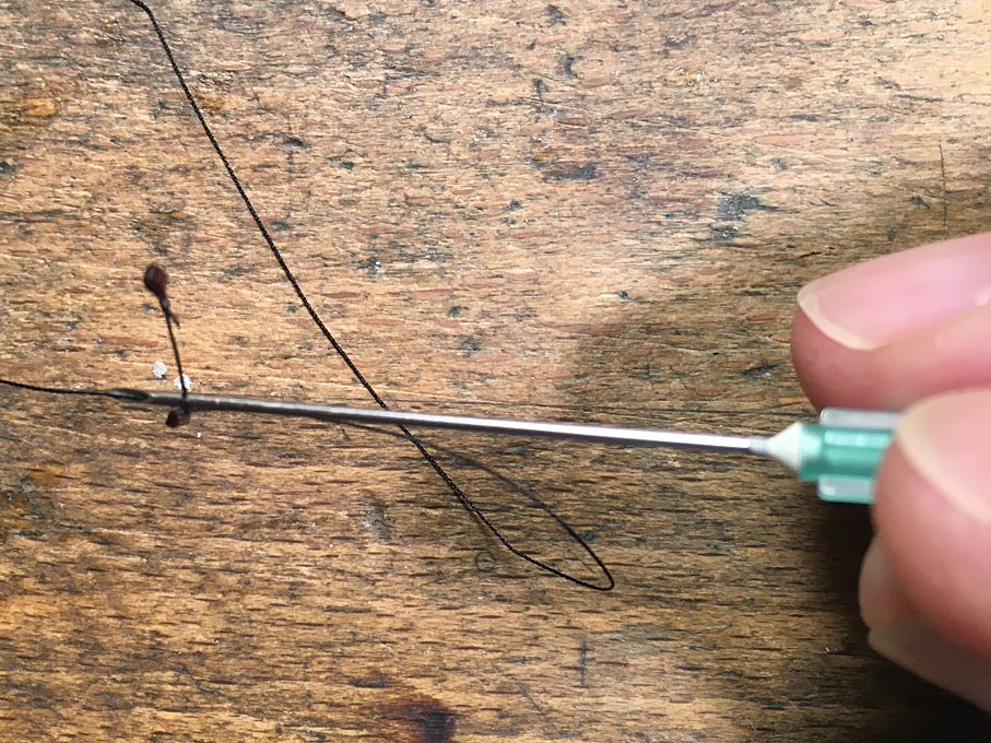
-
SMS Karlsruhe by Wreck1919 - 1/100
wefalck replied to Wreck1919's topic in - Build logs for subjects built 1901 - Present Day
Valery, that means then that sailors where standing in front of the yard, rather than behind it, when they were tending to whatever they had to tend to? Keith, double jack-stays became quite common particularly on the last deep-water sailing ships, when the massive steel yards would have meant that the upper part of the sails were actually lying on top of the yard and the foot-ropes were going around almost half of the yard. That part of the sail that lies on the yard doesn't pull, but would be subject to rot. So they move the jack-stay more forward. -
SMS Karlsruhe by Wreck1919 - 1/100
wefalck replied to Wreck1919's topic in - Build logs for subjects built 1901 - Present Day
These ropes are called 'foot-ropes' and the vertical ropes are the 'stirrups'. Valery's photos show very well the arrangement for yards that are meant for bending sails. On the first two pictures, however, there is a small error (sorry Valery): the stirrups should run over the back of the yard, not in front of it. The period photographs show why, so that the men can stand on the foot-ropes with the tummy on the yard. The yard on the KARLSRUHE only serves for the signal-halyards, so that the foot-ropes would have been used only occassionally, say to clear entangled halyards or something like that. So I would suspect that foot-ropes and halyards were galvanized wire rope, but probably served all over for protection. The stirrups perhaps were fixed to eye-bolts in the yard (no need for yackstays, as there were no sails) and had an eye in the end through which the footrope ran. I don't have access to my library at the moment, but once back home, I can check in Middendorf (1905), how footropes were made at the beginning of the 20th century. If I had to make them, I would use silk-covered copper wire (seidenumsponnene Kupferlitze in German) as is used for e.g. HF-coils. It seems to be easier to get again due to a fashion for analogue HiFi-equipment and restoration needs for old radios etc. Check Google for possible suppliers or ebay. The eyes can be bound with fine fly-tying thread and everything bent do shape and then painted black. -
Yes, mica (or more precisely muscovite) can be easily cut with scissors or scalpels. It's one of the softest minerals actually. I gather modellers of 18th or early 19th century ships use mica, because that is what was used often on the real ship. Mica as such is quite brittle, but when frames more elastic than glass. Also, before float-glass was invented, it was generally cheaper than glass. Not sure, it will work here, as it usually has a slightly streaky texture - it is a mineral and not all the molecules are arranged perfectly.
-
Ship in trouble by Ab Hoving - FINISHED
wefalck replied to Ab Hoving's topic in - Build logs for subjects built 1501 - 1750
Shame on me, somehow I missed this project ... very dramatic results indeed 👍🏻 -
Very glad to hear that your wife is on the way to mend. Well, we are not really acquaintances, but it was the second time within a few days that I had bad news about the health of a wife and this is always disturbing.
-
In theory, the window panes are inserted into recesses in the stiles and hold in place by strips of wood. So the stiles should be visible from both sides. That would be difficult reproduce in 1:87 scale, of course. Not sure what the physical size of the pilot house is, but one could use those very thin glasses as used in microscopy to cover samples. They are sold in packs of 100. They are very fragile, but can be cut to size with a scribing diamond. The stiles on back could be simulated just by paint. Otherwise, these very viscous acrylic gels used by model railway builders to glaze locomotive and coach windows could be a solution. I assume that is the same as the Testors product mentioned above. Talking about the stacks, if you allow me two observations: i think the stiffening bands are rather thick and it would be nicer, if it was bored out deeper. Personally, I would have turned them from either round aluminium or acrylic bar, which allows you to turn on the stiffening bands and to shape a nice flare. If you don't have a lathe, you could use styrene sheet around a wooden core.
-
Started catalogueing all my books nearly years ago. I am currently at no. 3514. Not all maritime though, lots of art books, 19th century engineering, and literature as well. Sadly we had to give most of my parents' library of another 3500 or so. I always carry a pdf of the latest MS Excel spreadsheet on my telephone in case I run across something interesting in a used bookstore - prevents me from buying duplicated. I largely stopped buying pre-1900 books in recent years (with some exceptions), as much of it is now available as digital copies. Saves money and space on my overflowing bookcases (30' x 8'). BTW. Everything that is marked with a 'B' in this list is an original hardcopy: https://www.maritima-et-mechanika.org/maritime/maritimebibliographies/maritimebibliography.pdf. But that was actually thread-drift. Back to the original question: By the middle of the 19th century, blocks and deadeyes were virtually flat on the surfaces. They were much easier to machine that way. Block- and deadeye-making machines were basically the first template-controlled lathes and milling-machines.
-
What I like about my toolmaker's vice shown earlier is that it has two rabbets in the jaws that allow you to clamp shorter parts without the need of parallels. Talking about parallels to prop up shorter material in a vice: I often use pieces of drill-rod instead - it's a lot cheaper than sets of parallels.
-
Sorry to hear these disturbing news. We keep fingers crossed that the surgery is successfull !
-
Watched last night the latest episode on the restoration of TALLY HO on YouTube and the precision of those woodworkers is just amazing always ....
- 174 replies
-
- 6
-
-
- Vigilance
- Sailing Trawler
- (and 1 more)
-
I am currently using so-called zapon-varnish for such things. It dries within minutes and was originally used mainly used to varnish silver and brass to prevent it from tarnishing. Old-fashioned nail-varnish is very similar in composition (not the modern acrylic one) and probably easier to find, though over here in Europe we find zapon-varnish in most DIY stores. Another option would be shellac, particularly the one in flakes that can be mixed with alcolhol to give any consitency, from honey-like to watery. It's an old-time means to stiffen paper, felt (as in bowler-hats), etc. It dries slower than the above varnishes. All obviously dry glossy, when applied to thick, so one may need to give it a spray with with some matte varnish. The nice thing is that all maipulations are reversible using a fews drops of aceton or alcohol. If you are not happy with the lay of thatch, brush some solvent over it, adjust and brush again some varnish on it. Repeat until you are satisfied with the looks.
-
What kind of varnish do you use? Personally, I would use one based on organic solvent, as a drop of solvent would soften it, allowing adjustments.
-
Not sure, what the final verdict on the thatching is now, but one could also use a technique akin to that that was used on the rial thing: put a thread of about the same colour as the thatching material and twice the length of the rancho on the double sided tape, place a bunch of the material on it, lay the loose end over the bunch and fix with varnish. Then put thread that was on top onto the tape, place the next bunch, and lay the thread that was on the bottom over it. And so on. In this way you kind sew the bunches together and they should lift of more or less as a unit. In real life the thatch would have been sewn to the rafters using hemp cord or a cord made from straw twisted together. The house thatchers had special long needles for that. Thinking about that using such sewing technique, you may be able to do the thatching directly on the rancho ...
-
I gather Brian can comment on this with more practical experience. However, usually the power of the laser can be modulated as well as the speed of travelling set, both of which determine the penetration of the laser-beam. There is a minium width of the cut plus kerf, but one can make the slots wider by running the laser with a slight off-set several times. The char from the laser could actually be beneficial as it protects the wood underneath from further smoldering during soldering.
-
He could also use the laser-cutter to engrave those slots ...
