


wefalck
-
Posts
6,444 -
Joined
-
Last visited
Reputation Activity
-

 wefalck got a reaction from FriedClams in SMS WESPE 1876 by wefalck – FINISHED - 1/160 scale - Armored Gunboat of the Imperial German Navy - as first commissioned
Folding tool update
After the first use of the tool, I immediately made a couple of modifications, which however, I had expected to introduce anyway.
When working with cardboard or paper one needs to ‘overbend’ the folds somewhat, so that they stay at the desired angle. This is different to working with soft sheet-metal. Styrene sheet also will have this spring effect. Therefore, the folding edges were given a 10° clearance angle. An angle of 15° may have been even better, but it works with the 10°. The edges are not really weakened by this.
The second modification was to place a spring washer under the folding ruler. I had in mind to do this right away, but could not find them in the first place. The washers lift up the ruler a bit, so that it is easier to slip the material under it.
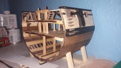
Gun operating platforms and gratings
The gun is mounted effectively on a turntable, so that platforms for crew are needed to give them access to the gun, while is being trained left or right. These platforms are made of wire gratings that are placed into angle-iron frames. The frames are suspended from the lower carriage by brackets. The pictorial evidence (photographs, drawings) is not detailed enough to fully understand what the brackets actually looked like and how and where exactly they were attached to the lower carriage frame. Some additional information is given by the Danish instruction model and the Russian clones in Suomenlinna fortress, but the carriages of these guns differ in detail from that on SMS WESPE. So the reconstruction of these platforms remains somewhat conjectural.
Crew standing on the gratings and operating the gun
Gratings of the Danish instruction model
Detail of gratings on a gun in Suomenlinna fortress
There are 13 gratings and steps in total, plus the platform for the gun-layer. The original plan was to photo-etch the frames from brass sheet, but with the arrival of the laser-cutter I changed this plan. The drawings were modified accordingly. The obvious solution to simulate the angle-iron frame was to design an open frame and then fold-up the vertical parts of the angle. However, it proved impossible to fold the narrow, 0.3 to 0.4 mm strips consistently and without distortions. Not sure this would have worked with the PE parts either. It was then decided to make the open frame and the vertical parts separately as narrow strips and glue them together with lacquer. After several iterations of drawings and laser-cutter settings to arrive a workable width of the strips etc. I arrived at an acceptable solution, albeit the ‘angle-irons’ are somewhat over-scale.
Example of a drawing for the gratings and their supporting brackets
Assembly was a slow and nerve-wracking process. I did not manage to do more than one grating per evening and it involved a lot of (mental) foul language. Eventually, I got them all together. Zapon-varnish was used throughout the assembly. The finished parts are surprisingly strong.
First Version with engraved surfaces of the platform for the gun-layer
Final Version of the platform for the gun-layer (5 mm grid on the cutting-mat)
The original plan was to simulate the wire-mesh of the gratings by real wire-mesh and I obtained from wires.co.uk some really fine mesh in brass and steel. The idea was to pull every second wire in one direction, as the original mesh was rectangular. It proved, however, very difficult to cut such small pieces (sometimes only 1.5 mm wide) from the wire-mesh. Then a present to wife in form of a box with various (fruit) teas came to my rescue: some of the teas came in bags made from extremely fine but lightly woven fabric. I do not know what material it is, but as it dissolves in acetone, it is probably cellulose acetate silk or Rayon. Such fabrics are also used in silk-screen printing and I had not chanced upon the tea-bags, I would have looked there. This silk-screen or fabric can be precisely and easily cut with a new scalpel blade. The small pieces of fabric were dropped into the frames and fixed at the edges with a light touch of varnish.
Tea-bag fabric
The platform for the gun-layer is a more complex structure. A 5 mm sheet-metal armour shield is meant to protect him from shrapnel and small-arms fire. The armour shield is reinforced at the edges with rivetted-on metal strips. The original plan was to produce this as a surface-etched part. I realised that the laser-cutter interprets half-tone images as instructions to modulate the laser power so that it does not cut all the way through. Laser-engraving in other words. It did produce the desired effect, albeit with the engraved surface being rather rough due to the digitising effect. However, this part then was so thin and flimsy, that it would not stay in shape, when attempting to shape the round corner. I reluctantly accepted that it would be somewhat over-scale in thickness and cut the armour shield and the reinforcing strips separately. They were glued on top of each other with varnish and then the round of the shield formed over a rod. Folding and gluing completed the process.
The collection of gratings and steps
I am not entirely happy with the result and tend to think, that etched parts may have looked finer. But then their assembly would have required a lot of very delicate soldering work – I don’t trust CA for metal/metal bonds too much. On the other hand, attaching the gratings to the lower carriage frame is likely to be easier for the cardboard parts than for brass parts. Before that can be done, I need to add the wheels, which requires a lot of handling ...
To be continued ...
-
wefalck got a reaction from FriedClams in SMS WESPE 1876 by wefalck – FINISHED - 1/160 scale - Armored Gunboat of the Imperial German Navy - as first commissioned
Thanks, gentlemen, much appreciated !
****************************************
Folding tool
As will be seen in the next post, quite a number of delicate laser-cut parts will need to be folded. Therefore, I thought a folding tool might come handy. A number of commercial gadgets are available, but considering that they essentially consist of a couple of milled-to shape pieces of aluminium and a thumb-screw, I find them rather overpriced at €20 to €70, depending on what you buy where. Also, if I have the right materials and tools, I prefer to make such things myself.
I did not have a suitable piece of flat aluminium in stock, so I decided to make it from some 4 mm thick Plexiglas off-cut. This has the added value that you can better see, where you place the folding edge. Plexiglas is more vulnerable than aluminium, but I can always make a replacement, should the need arise.
A set of fingers ranging from 1 mm to 6 mm width were separated by notches made with a 4 mm cutter. The front was bevelled for better access to small parts. The opposite side was left straight for longer parts. For the moment, the front edges where milled at 90° degrees, but I can imagine that a slight overbending would be better. I am considering to mill on a 5° or 10° relief angle, but will first test the piece in practice. A more acute angle will make the edges more vulnerable to chipping. The underside is somewhat recessed over most of the width, so that tool really clamps with the front edge, where it is needed, and does not wobble.
As I also did not have material for a base in stock, I decided to use the base of the sanding tool that I made a while ago. It has the added value that no extra gadget is floating around the workshop. The folding ruler was drilled and two corresponding holes in the base were drilled and tapped for M3 thumb-screws.
-

.thumb.jpg.6fd4c1b78768bb3efd745ab810936005.jpg) wefalck got a reaction from vaddoc in SMS WESPE 1876 by wefalck – FINISHED - 1/160 scale - Armored Gunboat of the Imperial German Navy - as first commissioned
wefalck got a reaction from vaddoc in SMS WESPE 1876 by wefalck – FINISHED - 1/160 scale - Armored Gunboat of the Imperial German Navy - as first commissioned
Loading crane
Somehow I seem to move two steps forward and then one step back again. For one part completed there are several that jump off the table to be never found again or that are destroyed during subsequent steps of manipulation ...
Mechanically, the loading crane is a relatively simple affair, a rope winding drum driven through a pinion and cog-wheel, powered by a hand-crank, and for turning a worm-wheel drive equally powerd by a hand-crank. The console on which the crane rests is a quite complex part that was bolted together from several cast parts.
The loading crane on the demonstration model in the former Naval Museum in Copenhagen
The winding mechanism of the charging crane
My first thought was to mill the console from the solid or rather to solder it together from several milled parts. I finally decided to put the laser-cutter to work and fabricate it from several cardboard pieces. On the bottom line, this was the easiest solution and compatible with the rest of the under-carriage
The crane on the demonstration model in Copenhagen mainly consists of bright pieces of steel or cast-iron. Whether this was the case too originally on the prototype cannot be verified anymore, as no detail photographs exist. It is perhaps doubtful due to the continuous maintenance required to keep rust at bay. Although, the navy was not concerned about camouflage at that time, they were aware of the risk of early detection by the enemy due to bright metal part reflecting the sun. However, I allowed myself the artisanal-aesthetic license of bright metal, as I think it will be a nice contrast to the dark green of the gun carriage later.
The actual crane was milled from a 2.5 mm steel rod. To this end the thickness profiles in both dimensions were taken off the original drawings and ‚stretched’ out straight in the CAD software. After milling, the part was softened in the flame, so that it could be bent according to the drawing. The hole and slot for the pulley were machined afterwards, as the part could break there during bending. The final shaping was done with silicone-bound grinding bits.
Milling of the crane in the dividing apparatus
Pulleys and forks form them are tiny parts machined on the lathe and the milling machine.
Fork for the lower guiding pulley
The mechanism of the crane consists of a good dozen of lathe-turned parts, that were, apart from their minute size, were not particularly challenging.
The cog-wheel, the pinion, and the worm-wheel were turned together with their axes in one piece. On the photographs I counted 60 teeth on the large wheel, which gives, together with a diameter of 3 mm a module of 0.05. Making a single tooth mill seem to be too much work, so that I took the short-cut of just gashing the wheels with a 0.1 mm thick circular saw. It is only about the look and I did not intend to make these gears functional. Hobbing a worm-wheel of just 1 mm diameter was too big of a challenge, big of a challenge, but at least I tilted the axis 20° when gashing it.
Milling of the pinion and the cog-wheel
Partly assembled loading crane
The final assembly can only be done, once the crane-console has been attached to the carriage and the whole thing is painted.
To be continued ...
-
 wefalck got a reaction from GrandpaPhil in Ship paintings
I don't think that such ships are an aberration - we probably will say the same thing about today's 'hybrid' cars one day. They represent the transition from one propulsion system to another with the associated uncertainties of reliability and availability of fuel supplies (before you could coal in Aden, the coal had to be shipped there first). Having both modes of propulsion increased the safety at sea and the probability that you actually got from A to B.
I love this transition period (in ship-building history) because it shows the introduction and progress of engineering and the (cautious) technological optimism of the time.
-
 wefalck got a reaction from Rik Thistle in Ship paintings
I don't think that such ships are an aberration - we probably will say the same thing about today's 'hybrid' cars one day. They represent the transition from one propulsion system to another with the associated uncertainties of reliability and availability of fuel supplies (before you could coal in Aden, the coal had to be shipped there first). Having both modes of propulsion increased the safety at sea and the probability that you actually got from A to B.
I love this transition period (in ship-building history) because it shows the introduction and progress of engineering and the (cautious) technological optimism of the time.
-
 wefalck got a reaction from Bob Cleek in Ship paintings
I don't think that such ships are an aberration - we probably will say the same thing about today's 'hybrid' cars one day. They represent the transition from one propulsion system to another with the associated uncertainties of reliability and availability of fuel supplies (before you could coal in Aden, the coal had to be shipped there first). Having both modes of propulsion increased the safety at sea and the probability that you actually got from A to B.
I love this transition period (in ship-building history) because it shows the introduction and progress of engineering and the (cautious) technological optimism of the time.
-
 wefalck got a reaction from Canute in Ship paintings
I don't think that such ships are an aberration - we probably will say the same thing about today's 'hybrid' cars one day. They represent the transition from one propulsion system to another with the associated uncertainties of reliability and availability of fuel supplies (before you could coal in Aden, the coal had to be shipped there first). Having both modes of propulsion increased the safety at sea and the probability that you actually got from A to B.
I love this transition period (in ship-building history) because it shows the introduction and progress of engineering and the (cautious) technological optimism of the time.
-
 wefalck got a reaction from mtaylor in Ship paintings
I don't think that such ships are an aberration - we probably will say the same thing about today's 'hybrid' cars one day. They represent the transition from one propulsion system to another with the associated uncertainties of reliability and availability of fuel supplies (before you could coal in Aden, the coal had to be shipped there first). Having both modes of propulsion increased the safety at sea and the probability that you actually got from A to B.
I love this transition period (in ship-building history) because it shows the introduction and progress of engineering and the (cautious) technological optimism of the time.
-
 wefalck got a reaction from Moab in Ship paintings
I don't think that such ships are an aberration - we probably will say the same thing about today's 'hybrid' cars one day. They represent the transition from one propulsion system to another with the associated uncertainties of reliability and availability of fuel supplies (before you could coal in Aden, the coal had to be shipped there first). Having both modes of propulsion increased the safety at sea and the probability that you actually got from A to B.
I love this transition period (in ship-building history) because it shows the introduction and progress of engineering and the (cautious) technological optimism of the time.
-
 wefalck got a reaction from lmagna in Ship paintings
I don't think that such ships are an aberration - we probably will say the same thing about today's 'hybrid' cars one day. They represent the transition from one propulsion system to another with the associated uncertainties of reliability and availability of fuel supplies (before you could coal in Aden, the coal had to be shipped there first). Having both modes of propulsion increased the safety at sea and the probability that you actually got from A to B.
I love this transition period (in ship-building history) because it shows the introduction and progress of engineering and the (cautious) technological optimism of the time.
-
 wefalck got a reaction from Edwardkenway in Ship paintings
I don't think that such ships are an aberration - we probably will say the same thing about today's 'hybrid' cars one day. They represent the transition from one propulsion system to another with the associated uncertainties of reliability and availability of fuel supplies (before you could coal in Aden, the coal had to be shipped there first). Having both modes of propulsion increased the safety at sea and the probability that you actually got from A to B.
I love this transition period (in ship-building history) because it shows the introduction and progress of engineering and the (cautious) technological optimism of the time.
-
 wefalck got a reaction from BETAQDAVE in Ship paintings
I don't think that such ships are an aberration - we probably will say the same thing about today's 'hybrid' cars one day. They represent the transition from one propulsion system to another with the associated uncertainties of reliability and availability of fuel supplies (before you could coal in Aden, the coal had to be shipped there first). Having both modes of propulsion increased the safety at sea and the probability that you actually got from A to B.
I love this transition period (in ship-building history) because it shows the introduction and progress of engineering and the (cautious) technological optimism of the time.
-
 wefalck got a reaction from John Allen in SMS WESPE 1876 by wefalck – FINISHED - 1/160 scale - Armored Gunboat of the Imperial German Navy - as first commissioned
Thanks, Pat ... but close-up photographs are really unforgiving, as one can also see in the following ...
********************************************************************************************************
Further work on the lower carriage
Back to the lower carriage. The (mor or less) central pivot determines its rotational axis, but the weight of the gun is actually supported by four (kind of) caster wheels running on cast-iron rails bolted to the bottom of the barbette.
The rails had been turned already a long time ago. The forks for the caster-wheels were fabricated from laser-cut cardboard. The wheels themselves are simple turned steel discs with a groove.
Caster wheels prepared for assembly
For the assembly, the rails were taped down onto an appropriately scaled print-out of the original plan of the vessel and carriage fixed with a clothes pin. The wheels and forks are temporarly united by axels made from short lengths of copper wire. The casters then were cemented under the carriage in the correct position with respect to both, the rails and the carriage frame, using again varnish.
Caster wheels in place
The wheels will have to be removed again before painting the carriage, because they will be left in bright steel. I do not know, whether this is correct for the flanges of the wheels, but it gives the whole arrangement are rather ‘technical’ look. The axles with cylindrical end-caps have already been prepared from steel rod and will be installed during the final assembly.
Caster wheels in place
To be continued ...
-
 wefalck got a reaction from Rudolf in SMS WESPE 1876 by wefalck – FINISHED - 1/160 scale - Armored Gunboat of the Imperial German Navy - as first commissioned
Thanks, gentlemen, for your kind words ...
********************************************
Scrollwork and name-plates
As I had tried laser-engraving on cardboard for the gun-layer stand, I wanted to try out this technique also for the scrollwork and the name-plates. Originally, I had foreseen to develop the scrollwork by printing the design onto a decal-sheet and then build it up by sculpting it over the printed lines with acrylic gel. The name-plates could have been surface-etched in brass. One could have etched, of course also the scrollwork in brass and then complete it with acrylic gel.
Best available image of the bow scrollwork and name-plate
It is not very clear what the scrollwork looked like when new and from what material it was made. The fact that it seems to have persisted intact over the whole life of these ships may indicate that it was actually cast in some metal, rather than carved in wood.
There are no close-up photographs of sufficient resolution in the black-white-yellow paint-scheme. Closer photographs are only available from a later period, when everything was painted over in grey and some of scrollwork may have been picked out in a darker grey. Originally it was probably painted in yellow-ochre with parts of gilded. In any case, available photographs are not clear enough to truly reconstract the scrollwork, so some interpretation was necessary.
In addition to the scrollwork per se, there was a shallow sculpture of the animal after which the ship was named, for SMS WESPE, of course, a wasp. Existing photographs only give a vague idea what these sculptures really looked like. In any case not for SMS WESPE.
Only available image of the stern scrollwork
There has also been some scrollwork at the stern, but pictorial evidence for this is rather scarce. There is only one known photograph that gives a full view of the stern of this class of ships and this was taken at the very end of their service life. Available copies of this photograph are not clear enough to really discern what the scrollwork actually looked like, so a fair amount of imagination is needed to recreate it.
Artwork for the bow scrollwork
Creating the basic artwork for the decoration was a multiple-step process. First a photograph of the respective section of the model as built was taken in order to give the necessary proportions. In the next step the best available photograph with the least perspective distortions was chosen and fitted over the model photograph. In another layer of the graphics software (Graphic for iPad) the scrolls were drawn free-hand (with the iPen) using the paintbrush-function and a good amount of smoothing. This artwork was saved as a JPEG. On the Internet I found a nice drawing of a wasp and turned this into a pure b/w image with a good bit of editing in Photoshop. Both, the scrollwork and the wasp were saved as transparent GIF. In my favourite CAD-program (EazyDraw), the parts were mounted together. This could have been done also in Photoshop, but I did have a scaled drawing of the bow-section in EazyDraw to which I exactly fitted the artwork. There were also some addtional parts to be cut.
Some examples of the (unused) laser-cut scrollwork and the name-plates
The scrollwork was cut/engraved with the laser-cutter using the ‘half-tone’ function, which means that the laser is modulated to emit less power when a grey pixel is encountered and full power, when a black pixel is encountered. I had to play in several iterations with the settings of the laser-cutter in order to arrive at a satisfactory result.
Scrollwork and name-plate in place
In a first try the name-boards were made in the same way, but the half-depth engraving around the letters resulted in a somewhat fuzzy apearance of the letters. I, therefore, tried out a different idea. From previous trials it was know that the laser had no effect on transparent materials and very limited effect on translucent materials. Hence, I covered some cardboard with a thin layer of Pleximon 192 (essentially liquid, light-hardening Plexiglas). A thorough curing this sandwich was sanded flat and presented to the laser-cutter. The laser removes all the cardboard, but leaves the acrylic virtually untouched, with the exception of some light surface roughness. One ends up with a piece of thin acrylic sheet to which the letters and the scrollwork of the name-board are attached. Within the limits of the resolution (0.05 mm) of the laser-cutter the lettering turned out reasonably clear, perhaps not as crisp, as when photoetched though.
Stern scrollwork in place
The scrollwork elements were attached to the hull using fast-drying varnish. The actual painting and guilding will be done, once the hull has been painted.
To be continued ...
-
wefalck got a reaction from Canute in WW2 ship drawings anyone know what this is?
The ship was apostrophed as 'motonavi per linee minori', which means 'motorships for minor shipping lines'. That 'motonavi' is plural may indicate that this plan pertain to a class of ships, rather to specific one.
-
wefalck got a reaction from FriedClams in Germania Nova 1911 by KeithAug - FINISHED - Scale 1:36 - replica of schooner Germania 1908
Why and since when cowl vents are painted red inside still seems to be an unresolved question. We have been discussing in various fora etc. for the Imperial German Navy, but the discussions remained unconclusive.
At some stage white seems to have been common, apparently to serve as a light conduit as well. I have also seen black ones - e.g. the boiler-room ventilators on my SMS WESPE at least in the early years; presumably to make coal dust less visible. French ventilators in the 19th century seem to have been the same colour outside and inside.
Another suggestion for the choice of red as colour has been that it resembles (faintly) the copper from which many early (smaller) ventilators were made.
-
wefalck got a reaction from Canute in Lower cost (?) shiny metal parts
OK, that is a rather unusual application. Paint pigments, particularly those used for high-quality air-brush painting are so small that they seem to diffuse into other materials. I had an issue with that.
-
wefalck got a reaction from Canute in Lower cost (?) shiny metal parts
We had this discussion here in another thread: why are people so keen to put layer over layer of stuff onto their parts ? What is the point of 'immersing' in epoxy resin after painting or to 'seal' it ? If its going to be toy that will be handled that makes sense, or if you want to change the sheen of the surface, but otherwise your paint is the surface treatment.
UV-induced polymerisation does have a time constant and can be sped up by adding more quantums of UV-light. The printing process just induces the process, but the cross-linking may not have completed yet once the part is taken out of the printer. That's why the parts are exposed again to UV-light, either in a special UV-chamber or to natural sunlight. It is important that the resin is fully cured before you cover the part with something that likely absorbs the UV-radiation, as pigmented paint would.
-
wefalck got a reaction from mtaylor in The Yellow in Royal Navy colour schemes 1870-1880
As a matter of fact, we do have a fairly detailed picture of the paint schemes to be applied on the basis of the ordinances published in the respective offcial gazette. Up to 1895 the black-white-yellow scheme was valid that seems to have been the predominant scheme in virtually all navies around the world. After that grey, with initially hulls in a darker grey, was adopted. The hulls of ships at foreign (tropical) stations were painted white after 1890, reflecting the need to protect the crews below deck from heat stress due to hulls painted black - there was virtually no forced ventilation at that time. After 1895 the yellow for funnels, ventilators etc. was replaced by grey for ships at foreign station, but the hulls remained white. The yellow used after about the 1880s seems to have become darker and more orangy.
The exact hue of that yellow used by the different nations varied from nation to nation and also over time, perhaps also as a matter of fashion. It appears that up to the third quarter of the 19th century the yellow was comparatively pale and then became darker. The French used a decidedly 'murky' yellow although they have one of the classical sources of yellow and red ochre in the Roussilon area that supplied much of the artistic world.
-
wefalck got a reaction from mtaylor in The Yellow in Royal Navy colour schemes 1870-1880
@uss frolick Thank you. I have been well aware of HMS GANNET and created a photo-essay on her some ten years ago, while she was still undergoing some restoration: https://www.maritima-et-mechanika.org/maritime/chatham/chatham.html. It is not clear (to me) to what state of her life she actually was restored to, but I believe it is definitely a post-1880 stage. It may be still worthwhile to talk to Chatham about their restoration decisions.
@grsjaxOf course, I am well aware of the difficulties around recreating colours, even if you know the recipes and the pigments for the paint used. This is why in Germany in the time between the wars the 'Reichsausschuß für Lieferbedingungen' (RAL, roughly National Committee for Supply Specifications) was set up. One of its tasks was the standardisation of colours, which led to the RAL colour charts still in use today.
The respective paint most likely contained natural ochre, lead-white and lineseed-oil as the main ingredients, perhaps in addition chalk as cheaper pigment then lead-white. However, there are rather wide variations in the hue of natural ochre, ranging from a pale yellow to almost red, depending on its chemical and mineralogical composition.
For these reasons I have been hoping to identify artefacts that show original paint or the impression artists had of the original hue.
-
wefalck got a reaction from mtaylor in Lower cost (?) shiny metal parts
We had this discussion here in another thread: why are people so keen to put layer over layer of stuff onto their parts ? What is the point of 'immersing' in epoxy resin after painting or to 'seal' it ? If its going to be toy that will be handled that makes sense, or if you want to change the sheen of the surface, but otherwise your paint is the surface treatment.
UV-induced polymerisation does have a time constant and can be sped up by adding more quantums of UV-light. The printing process just induces the process, but the cross-linking may not have completed yet once the part is taken out of the printer. That's why the parts are exposed again to UV-light, either in a special UV-chamber or to natural sunlight. It is important that the resin is fully cured before you cover the part with something that likely absorbs the UV-radiation, as pigmented paint would.
-
 wefalck got a reaction from shipman in The Yellow in Royal Navy colour schemes 1870-1880
@uss frolick Thank you. I have been well aware of HMS GANNET and created a photo-essay on her some ten years ago, while she was still undergoing some restoration: https://www.maritima-et-mechanika.org/maritime/chatham/chatham.html. It is not clear (to me) to what state of her life she actually was restored to, but I believe it is definitely a post-1880 stage. It may be still worthwhile to talk to Chatham about their restoration decisions.
@grsjaxOf course, I am well aware of the difficulties around recreating colours, even if you know the recipes and the pigments for the paint used. This is why in Germany in the time between the wars the 'Reichsausschuß für Lieferbedingungen' (RAL, roughly National Committee for Supply Specifications) was set up. One of its tasks was the standardisation of colours, which led to the RAL colour charts still in use today.
The respective paint most likely contained natural ochre, lead-white and lineseed-oil as the main ingredients, perhaps in addition chalk as cheaper pigment then lead-white. However, there are rather wide variations in the hue of natural ochre, ranging from a pale yellow to almost red, depending on its chemical and mineralogical composition.
For these reasons I have been hoping to identify artefacts that show original paint or the impression artists had of the original hue.
-
 wefalck reacted to Forlani daniel in Chebece 1750 by Forlani daniel - FINISHED - 1:48
Good morning, everyone, thank you very kindly.
More photos.
Un Saluto.
-
wefalck reacted to Forlani daniel in Chebece 1750 by Forlani daniel - FINISHED - 1:48
Good morning and thank you all.
More photos
Un saluto.
-
wefalck got a reaction from Canute in Air Brush system
When choosing an airbrush and a compressor, one should also think about the likely size of the area that one will be spraying and how often per year you are going to use it. In many cases one should get away with a rather smallish outfit. It may take longer, but it is easier to work on larger areas with an airbrush with a fine nozzle than the other way around.
Working with solvent-based paints in an air-brush is messy and probably not very healthy unless you have a suitable extraction fan at your workplace. Solvents cannot be disposed off in the sink, therefore the airbrush has to be cleaned over a collecting vessel. In consequence, you may not clean it as thorough as you should. Equipment failure may be the result.
For this reason, I only use acrylics. The airbrush can be thorough cleaned under running water.
It depends on the use of the model and how it will be handled, but for static models that disappear inside a display cabinet once completed, I use paints pre-thinned for airbrushing from reputable artist supply houses/paint manufacturers, e.g. Vallejo (Spain), Schmincke (Germany). They never let me down and I don't have issues with clogging etc.