


wefalck
-
Posts
5,629 -
Joined
-
Last visited
Reputation Activity
-

 wefalck got a reaction from mtaylor in Armchair wreck-hunting
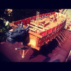
If you go to location 52°33'07.02" N 4°36'10.96" E in GoogleEarth, you will see just a beach off Castricum in the Netherlands. However, when you switch to the 2005 image, you will see the ghost of S.M.S. SALAMANDER, which was an armoured gunboat of 1872 of the Imperial German Navy. She sank there in a storm in 1919 being towed to the Netherlands to be broken up. The shifting sands now seem to have covered her remains that were still visible in 2006 at very low tide. At some stage attempts were made to salvage and restore her, but it proved to difficult and costly.
S.M.S. SALAMANDER was one of the boats of the WESPE-Class, the prototype of which I am currently building: http://www.maritima-et-mechanika.org/maritime/models/wespe/wespeclass.html (see also the building log on the forum).
-
 wefalck got a reaction from CDR_Ret in Armchair wreck-hunting
If you go to location 52°33'07.02" N 4°36'10.96" E in GoogleEarth, you will see just a beach off Castricum in the Netherlands. However, when you switch to the 2005 image, you will see the ghost of S.M.S. SALAMANDER, which was an armoured gunboat of 1872 of the Imperial German Navy. She sank there in a storm in 1919 being towed to the Netherlands to be broken up. The shifting sands now seem to have covered her remains that were still visible in 2006 at very low tide. At some stage attempts were made to salvage and restore her, but it proved to difficult and costly.
S.M.S. SALAMANDER was one of the boats of the WESPE-Class, the prototype of which I am currently building: http://www.maritima-et-mechanika.org/maritime/models/wespe/wespeclass.html (see also the building log on the forum).
-
 wefalck got a reaction from thibaultron in Armchair wreck-hunting
If you go to location 52°33'07.02" N 4°36'10.96" E in GoogleEarth, you will see just a beach off Castricum in the Netherlands. However, when you switch to the 2005 image, you will see the ghost of S.M.S. SALAMANDER, which was an armoured gunboat of 1872 of the Imperial German Navy. She sank there in a storm in 1919 being towed to the Netherlands to be broken up. The shifting sands now seem to have covered her remains that were still visible in 2006 at very low tide. At some stage attempts were made to salvage and restore her, but it proved to difficult and costly.
S.M.S. SALAMANDER was one of the boats of the WESPE-Class, the prototype of which I am currently building: http://www.maritima-et-mechanika.org/maritime/models/wespe/wespeclass.html (see also the building log on the forum).
-
 wefalck got a reaction from druxey in Wood Preservative/Stabilizer
Ship models are usually kept indoors, so there is not really a need for preservation or stabilisation. There may be issues with woodworms (anobium punctatum), but this is a long-term preservation issue. In some parts of the World you may be also worried about termites, I gather.
Otherwise, the surface of wood is usually treated for esthetic reasons mainly. Covering the surface with some sort of lacquer or varnish also allows for easier cleaning, which again may not be an issue for a ship model that is kept best under a glass cover anyway.
Outdoor wood preserving agents that contain various organic or inorganic biocides would actually be most unsuitable for indoor use because they may give of hazardous fumes or may be toxic when people/pets come into contact with them. For the same reason, one should not (re-)use such wood (e.g. old railway sleepers etc.) indoors.
-
 wefalck got a reaction from archjofo in SMS WESPE 1876 by wefalck – 1/160 scale - Armored Gunboat of the Imperial German Navy - as first commissioned
Thanks for the praise to all
I think there are numerous tutorials on the Web on photoetching, Matie. I am using pre-prepared brass sheets available from various vendors. In order to keep things simple I work with small frets only and use small vessels, such as plastic film containers, for the processes. Compared to professional foam-etched parts, my shop-products are not that well-defined at all. It is not so easy to agitate the parts in the etching solution sufficiently uniformly. In fact, I produced probably two bad parts for every good one. In the end I picked the best parts from all tries.
Surface etching (e.g. rivets) is simple, you just need two different masks for both sides. As you can see from the pictures in the post above, one mask just covers the areas not to be etched-away, namely the rivets and other raised features.
-

.thumb.jpg.6fd4c1b78768bb3efd745ab810936005.jpg) wefalck got a reaction from vaddoc in SMS WESPE 1876 by wefalck – 1/160 scale - Armored Gunboat of the Imperial German Navy - as first commissioned
wefalck got a reaction from vaddoc in SMS WESPE 1876 by wefalck – 1/160 scale - Armored Gunboat of the Imperial German Navy - as first commissioned
Working close to the collet improves precision due to less run-out and side-play, which are minimal on a watchmaker's lathe already ...
*******
Completing the capstan
Again the guiding rollers are a simple turning job. The shapes were produced with a free-turning graver and by rotary milling in the dividing head.
Using a worm-driven dividing head to round-mill the head of the chain-rollers
Using a worm-driven dividing head to round-mill the head of the chain-rollers
In the meantime various etched parts had been produced, including the base plate made up of two different superimposed parts and minuscule pawls. Also a chain separator from 0.3 mm copper wire rolled flat was produced. The various parts were soldered together.
The etched parts for the spills
The completed capstan (lower left corner, the grid of the cutting mat is 10 mm x 10 mm)
To be continued ...
-
 wefalck got a reaction from GrandpaPhil in SMS WESPE 1876 by wefalck – 1/160 scale - Armored Gunboat of the Imperial German Navy - as first commissioned
The base for the double bollards were intended to be a surface-etched parts, but I was not happy with the results I produced in my simple home-etching arrangement. So I decided to make them from solid brass. Solid brass was easier to handle for machining than brass sheet. Nevertheless the envisaged machining operations prompted me to make a couple of gadgets, fixtures, for the mill and the lathe.
Drilling of the bollard-bases in the work-holding block
Milling around the edges or on top of flat material always presents work-holding problems. Worse, if several identical parts have to be produced. Hence I divined a work-holding block with several clamps and stops running in a T-slot.
Milling a bevel to the bollard-bases
Similarly holding small parts for cutting off on the circular saw is tricky and best done on the lathe with a special saw table clamped to the top-slide. This saw table allows parts to be safely clamped down for cutting.
Cutting-off individual bollard-bases
The three parts for each bollard (apologies for the poor picture)
The three parts of each bollards were soft-soldered together.
Work-holding for soldering
The finished bollards on the top-left (the other parts will be discussed later)
To be continued ...
-
wefalck got a reaction from GrandpaPhil in SMS WESPE 1876 by wefalck – 1/160 scale - Armored Gunboat of the Imperial German Navy - as first commissioned
Deck Fittings
The hull taking shape, at least in its rough outline, I turned my attention to some pieces of deck fittings. I know, many modellers more or less complete the hulls etc. including the paintwork first, but as many pieces may require repeated handling and fitting on the hull, I leave these finishing touches to the end.
Bollards
The ships were fitted with four pairs of bollards of square cross section; two at the rear and two on the raised quarterdeck. Luckily a good, rather close-up photograph of the real specimen is available.
Rear deck with emergency steering stand and other pieces of deck fittings
The bollards are milled from round brass stock. Round stock was chosen as a starting point rather than e.g. flat stock, because it can be held easily in the lathe for turning on a spigot, by which the part can be held for further machining. Otherwise it would be difficult to mount such a small part on the miller for machining on five sides. The spigot is a convenient reference for machining and for fastening the part on the model eventually.
Indexing head on the milling machine
Before the milling operations
From the lathe the raw part is transferred to an indexing head mounted on the milling machine. After each pass with the cutting tool, the part is turned by 90º or 180º depending on requirements. Thus a square and symmetric part is produced.
Milling nearly completed
For a final machining step, the part is transferred back to the lathe and the dome shaped head formed using a very fine file on a roller-filing rest.
The nearly finished bollard with the roller-filing rest in the foreground
The job is completed by rounding off the corners using a not-too-hard rubber-bonded abrasive wheel (CRATEX) in the mini-drill. Remaining machining burrs are removed by offering the part to wire brush wheel.
The bollards on part of the working drawing
To be continued with the bases for the bollards ...
-
 wefalck got a reaction from avsjerome2003 in Shop-made filing-machine
Well, too much travelling the last few weeks resulted in little progress. It is frightening to think I started this project already in March, thinking that I would quickly return to my WESPE-class gun-boat project …
******
The excentric rod was turned from a piece of steel, while the actual lever with the ball end is a recovered piece from a similar broken commercial product. For other pieces of equipment I turned such levers myself using a ball-turning attachment.
Method for turning the excentric for the holding-down bolt
Holding- down bolt and excentric lever assembly
Table bearing barrel and locking arrangement
To be continued ...
-
 wefalck got a reaction from aviaamator in Shop-made filing-machine
Well, too much travelling the last few weeks resulted in little progress. It is frightening to think I started this project already in March, thinking that I would quickly return to my WESPE-class gun-boat project …
******
The excentric rod was turned from a piece of steel, while the actual lever with the ball end is a recovered piece from a similar broken commercial product. For other pieces of equipment I turned such levers myself using a ball-turning attachment.
Method for turning the excentric for the holding-down bolt
Holding- down bolt and excentric lever assembly
Table bearing barrel and locking arrangement
To be continued ...
-
 wefalck got a reaction from JerseyCity Frankie in Keeping polished brass from tarnishing?
Traditionally, brass and silver are protected from oxidation by applying a coat of cellulose nitrate (collodium) dissolved in amylacetate, ethanol and ethylacetate. In Germany such lacquers are known under the name Zaponlack and can be bought as commercial formulations from D.I.Y. stores.
-
 wefalck got a reaction from Canute in Micro-Mark MicroLux LaserKnife 2525 – A Review
Hi Mark,
I have been tossing with the idea of getting one of these cheapo units, but your experience really put me off becoming an 'early adopter'. There is a lot of potential in laser-cutting, but as with every tool you get what you pay for. Also this experience seems to confirm the wisdom that these Chinese machines (whether manufactured to foreign specs or direct imports) should be rather considered an assembly of parts in an advanced state of machining … a starting point for a project
I may come back to this, when my eye-sight gets too bad for working on small parts - hopefully in another couple of decades or so.
-
wefalck got a reaction from Canute in Wood Preservative/Stabilizer
Ship models are usually kept indoors, so there is not really a need for preservation or stabilisation. There may be issues with woodworms (anobium punctatum), but this is a long-term preservation issue. In some parts of the World you may be also worried about termites, I gather.
Otherwise, the surface of wood is usually treated for esthetic reasons mainly. Covering the surface with some sort of lacquer or varnish also allows for easier cleaning, which again may not be an issue for a ship model that is kept best under a glass cover anyway.
Outdoor wood preserving agents that contain various organic or inorganic biocides would actually be most unsuitable for indoor use because they may give of hazardous fumes or may be toxic when people/pets come into contact with them. For the same reason, one should not (re-)use such wood (e.g. old railway sleepers etc.) indoors.
-
wefalck got a reaction from mtaylor in Wood Preservative/Stabilizer
Ship models are usually kept indoors, so there is not really a need for preservation or stabilisation. There may be issues with woodworms (anobium punctatum), but this is a long-term preservation issue. In some parts of the World you may be also worried about termites, I gather.
Otherwise, the surface of wood is usually treated for esthetic reasons mainly. Covering the surface with some sort of lacquer or varnish also allows for easier cleaning, which again may not be an issue for a ship model that is kept best under a glass cover anyway.
Outdoor wood preserving agents that contain various organic or inorganic biocides would actually be most unsuitable for indoor use because they may give of hazardous fumes or may be toxic when people/pets come into contact with them. For the same reason, one should not (re-)use such wood (e.g. old railway sleepers etc.) indoors.
-
wefalck got a reaction from mtaylor in Micro-Mark MicroLux LaserKnife 2525 – A Review
Hi Mark,
I have been tossing with the idea of getting one of these cheapo units, but your experience really put me off becoming an 'early adopter'. There is a lot of potential in laser-cutting, but as with every tool you get what you pay for. Also this experience seems to confirm the wisdom that these Chinese machines (whether manufactured to foreign specs or direct imports) should be rather considered an assembly of parts in an advanced state of machining … a starting point for a project
I may come back to this, when my eye-sight gets too bad for working on small parts - hopefully in another couple of decades or so.
-
 wefalck got a reaction from GLakie in Micro-Mark MicroLux LaserKnife 2525 – A Review
Hi Mark,
I have been tossing with the idea of getting one of these cheapo units, but your experience really put me off becoming an 'early adopter'. There is a lot of potential in laser-cutting, but as with every tool you get what you pay for. Also this experience seems to confirm the wisdom that these Chinese machines (whether manufactured to foreign specs or direct imports) should be rather considered an assembly of parts in an advanced state of machining … a starting point for a project
I may come back to this, when my eye-sight gets too bad for working on small parts - hopefully in another couple of decades or so.
-
 wefalck got a reaction from Jack12477 in Micro-Mark MicroLux LaserKnife 2525 – A Review
Hi Mark,
I have been tossing with the idea of getting one of these cheapo units, but your experience really put me off becoming an 'early adopter'. There is a lot of potential in laser-cutting, but as with every tool you get what you pay for. Also this experience seems to confirm the wisdom that these Chinese machines (whether manufactured to foreign specs or direct imports) should be rather considered an assembly of parts in an advanced state of machining … a starting point for a project
I may come back to this, when my eye-sight gets too bad for working on small parts - hopefully in another couple of decades or so.
-
 wefalck got a reaction from Boxbuilds in SMS WESPE 1876 by wefalck – 1/160 scale - Armored Gunboat of the Imperial German Navy - as first commissioned
The base for the double bollards were intended to be a surface-etched parts, but I was not happy with the results I produced in my simple home-etching arrangement. So I decided to make them from solid brass. Solid brass was easier to handle for machining than brass sheet. Nevertheless the envisaged machining operations prompted me to make a couple of gadgets, fixtures, for the mill and the lathe.
Drilling of the bollard-bases in the work-holding block
Milling around the edges or on top of flat material always presents work-holding problems. Worse, if several identical parts have to be produced. Hence I divined a work-holding block with several clamps and stops running in a T-slot.
Milling a bevel to the bollard-bases
Similarly holding small parts for cutting off on the circular saw is tricky and best done on the lathe with a special saw table clamped to the top-slide. This saw table allows parts to be safely clamped down for cutting.
Cutting-off individual bollard-bases
The three parts for each bollard (apologies for the poor picture)
The three parts of each bollards were soft-soldered together.
Work-holding for soldering
The finished bollards on the top-left (the other parts will be discussed later)
To be continued ...
-
wefalck got a reaction from GrandpaPhil in SMS WESPE 1876 by wefalck – 1/160 scale - Armored Gunboat of the Imperial German Navy - as first commissioned
… don't have a gun license
****************************
The upper gun carriage
Based on the profile drawings from (http://www.dreadnoughtproject.org)
Part view of the drawings for the photo-etched upper carriage cheeks
Surface etched cheeks for the upper carriage
Filler and covering pieces laid out for soldering
Assembled cheeks and ties laid out
A core for the cheeks was sawn from 0.8 mm brass sheet and the etched covers soldered on. Then 'rivetted angle-irons', from etched parts were soldered on. These are connected by tie-plates. The frame of the upper carriage is also strengthend by horizontal ties. These are composites from several etched parts in order to show the rivetting. The horizontal ties were soldered to the side pieces, while the bulkhead-like ties were glued in because it would have been to difficult and risky to bring the heat for soldering at the right places. The covers for the trunnion-bearings were bent from an etched part and soldered together.
Assembled upper gun carriage from the rear
Assembled upper gun carriage from the front
The upper carriage was further kitted-out with wheels. The front and rear rollers were turned from steel to give them a real 'steel' appearance. On the prototype the rear rollers sit in excentric bearings that allows them to be brought into to contact with the rails on the lower carriage: when being fired the upper carriage slides back on these rails, the rollers allow it to roll back into the firing position.
Carriage with the barrel in place. Note the trunnion bearings cover (not yet trimmed to length)
Added the rollers plus the sockets aft for the lever that is used to turn the excentric bearings of the rear rollers
(Sorry, replaced the toothpick with a match - normal size not the large fire-place one )
To be continued ...
-
wefalck got a reaction from Canute in galvanized fittings and chain
If you are using brass throughout, a good base may be chemical tinning. I cannot recommend a reagent source for this in US though.
After thorough cleaning and degreasing (as you would do for blackening) you immerse the parts in the solution until a coating has formed. Initially the coating is of a dull silver, which looks quite like galvanised steel. You can touch up places also with paint as noted above. Rubbing a soft lead pencil over areas that would show wear makes it look more like bare steel.
-
 wefalck got a reaction from trippwj in Colors on ships
Our aesthetics are still dominated by the 18th century classicistic scholars and the re-discovery of medieval and earlier art in the early 19th century. At that time much of the original paint on buildings and other artefacts had crumbled away and faded. Hence, we tend to expect either the 'pure' material (wood, marble, other stone), rather than a colourful paint-scheme. Modern archeological techniques, however, have revealed many traces of paint that allow us to reconstruct paint-schemes and painting techniques. As a result, one must assume that many ships and buildings over history were painted in rather garish colours.
There is no comprehensive study on colours and paints used in decorating and preserving ships. It is quite certain, however, that the dominant pigments were mineral ones because they were cheap and stable. Many plant-derived pigments, particularly reds, are not permanent, i.e. they will fade when exposed to sunlight. Yellows, brick-reds and browns are all iron(hydr)oxides that are derived from natural ochre that has been heated to varying degrees and they are relatively cheap. Blues and greens can be derived from cobalt- or copper-containing minerals or synthesised from salts of these metals. They are more expensive. White, being derived from chalk or lime is cheap too. This gives you the main palette and other colours can be produced by mixing pigments.
As we all know, due to the long-wave light absorption by the water vapour in the air, colours appear to become more blue and paler the more distant you are from the painted object. In order to sufficiently impress across the typical viewing distance of several hundred meters you have to use a more garish paint scheme. Of course, if you reproduce this on a model that is being viewed from a short distance, it may not be very pleasing aesthetically to the modern beholder. Even modern replicas, such as the UTRECHT statenjacht or the frigate HERMIONE are not really pleasing to the eye that has been trained by museum models and old paintings.
Old paintings are another problem. Often the varnish on them tones down the original colour scheme. I have been shocked, when I discovered the original bright colouring in some paintings that I have known before their varnish was stripped off and they were cleaned.
-
 wefalck got a reaction from Mfelinger in Shop-made filing-machine
Good point, thibaultron, about the hand-files that are cut for the push stroke, while machine files have a socket at both ends, but normally are inserted in such way, that they cut on the down-stroke of the machine. I also acquired a couple of diamond-studded stub-files with prismatic resp. cylindrical cross-section for use in filing machines; the obviously cut in both directions.
*****************
The lathe-turned part for the bearing-barrel was sawn in half and the two halfs were clamped end on in the vice after careful alignment. With a fly-cutter the surface was milled perfectly flat and the diameter reduced to bring the rotational axis of the table into its surface.
Milling flat the halves of the bearing-barrel
The position for the barrel was marked out on the piece of 4 mm aluminium that will become the table. In the following step the positions for the mounting screws were marked out and drilled mit a 3 mm drill on the drill press. The two half-barrels then were stuck onto the table with a few drops of cyanoacrylate glue after careful alignment.
Bearing-barrel in position on the underside of the filing-table
The positions for the mounting screws then were marked with a transfer-punch. A light knock separated the parts again, which were then transfered to the mill for drilling and tapping M3 of the mounting holes. I usually start the tap on the mill with a few turns to ensure it is perfectly concentric to the hole and vertical. The tapping is completed by hand.
Drilling and tapping the mounting holes for the table on the bearing-barrel
Sqaring the edges of the aluminium plate for the filing-table proved to be just at the edge of the capacity of the milling machine. The plate was clamped to the vice on the mill with a C-clamp and the edges milled flat.
Squaring the edges of the filing-table
With the bearing-barrel screwed onto the underside of the table, the assembly was bolted to the table of the milling machine for milling the slot for the holding-down bolt. This holding down-bolt will be tightened using a excentric lever.
Milling the slot for the holding-down bolt
To be continued ...
-
wefalck got a reaction from Mfelinger in Shop-made filing-machine
The work on SMS WESPE has once more stalled a bit, because I got side-tracked by some engineering work. I wanted to first complete the model, but then realised that a filing-machine would come handy when making certain parts …
The die-filer is a machine that has all but disappeared from modern workshops. I suppose there are several reasons for this. Many consumer goods and toys that once would have been made from (folded) sheet-metal parts are now made from injection-moulded parts. For more delicate sheet-metal parts also photo-etching is being used. I believe the watchmaking and jewelry industry still uses stamped parts. However, also the methods for making dies has changed. While the stamp can be worked on using milling- and grinding-machines, this is often not possible with the dies, particularly, when they have to have sharp internal corners. The die-filer with its reciprocal, rather than rotary, movement allowed to do this. An inclinable table was needed to work-in the relief that permitted the stamped parts to drop out of the die. Today, electrical discharge machining (EDM) and laser erosion has replaced the old technique. Hand-held filing machines are still in use for work on injection moulds and similar tasks on complex surfaces.
In a small model-engineering workshop, the die-filer still has its uses, mainly to work on precision sheet-metal parts and when one has to ensure that the worked-on surface has a defined angle with respect to another. A die-filer can also be used as a scroll saw. For this reason, castings for constructing a simple die-filer are still being sold commercially and and some small specialised machine maufacturers still produce different machines, mainly for the jewelry manufacturers. However, the latter ones are rather heavy and costly.
Filing-machine for the jewel-making industry (http://www.walther.ch/hwz/d-fm77.htm)
Kit for a filing-machine (http://www.martinmodel.com/MMPtools-subfiles/MMPtools-sub.html)
Some bench-lathe manufacturer also offered filing-attachments that were driven from the lathe headstock. As the filing-machine is useful for clock-making, e.g. for working on the spokes of clock-wheels, some people made their own attachments for WW-type lathes and they are highly priced, when they appear at auctions.
Cataract filing-machine for their bench-lathes (see: http://www.lathes.co.uk/cataract/index.html)
Filing-machine from a 1913 catalogue of an unknown German maker
Drawings for a filing-machine from a 1913 catalogue of an unknown German maker
Building a filing-machine has been on my agenda for quite some time. With this in mind, I was able to purchase a treasure lot of rare Vallorbe machine-files. The lot contained round, half-round, tri-angular, and square files starting from 1 mm diamater resp. 1 mm x 1 mm cross-section, going up to 4 mm x 4 mm, and of various cuts. Unlike most other types of files, machines files are prismatic across their whole length and have uncut shanks at both ends.
Treasure-box with machine-files
A selection of machine-files
I first thought about converting my only moderately useful Proxxon DS 230/E scroll-saw into a filing machine. However, the table would not tilt and the holders for the saw blade were difficult to adapt. Then a broken jigsaw attachment for a power-drill came into my possession. Having no need for such attachment, the idea of converting it into a filing-machine emerged. The jigsaw was completely stuck nothing moved, and the sole plate was broken off. After having drilled out the screws that held the lid, the reason was obvious: it was completely filled with saw-dust, including the ball-bearing, presumably because it was upside down used under a saw-table. After dismantling and thorough cleaning it worked again. This meant, that I had the mechanism and the casting forming the basis for a filing-machine.
The disassembled jigsaw
According to the tables in the machine catalogue fo 1913, from which above illustrations were taken, the maximum stroke frequency would be around 400 per minute for hard materials, or less for softer materials. I sourced in China a geared electric DC motor that is rated to have 400 RPM at 12V. The output torque should be sufficient for the machine to be driven directly.
Geared 12 V DC motor to drive the filing machine
In order to minimise the slot for the files, allowing to work on small pieces, the rotational axis for the tilting machine table should be in its surface plane and also should not move out of the centre line. The foot of the jigsaw was arranged in a similar way and only needed to be adapted. The table will rest on a half-round barrel that can be clamped down onto a corresponding bearing surface. I had some 40 mm diameter alumium in my stock from which I turned the barrel. It will be sawn into half and screwed to the aluminium machine table. The bearing for the barrel was milled accordingly. Similarly, some of the future bearing surfaces on the casting were milled flat, which just went up to the capacity of my milling machines. Luckily the zinc die-cast material of the jigsaw housing is easy to mill.
Set-up for milling the bearing of the tilting table
Part-machined jigsaw casting
To be continued, once I got over my flu ...
-
wefalck got a reaction from avsjerome2003 in Shop-made filing-machine
Good point, thibaultron, about the hand-files that are cut for the push stroke, while machine files have a socket at both ends, but normally are inserted in such way, that they cut on the down-stroke of the machine. I also acquired a couple of diamond-studded stub-files with prismatic resp. cylindrical cross-section for use in filing machines; the obviously cut in both directions.
*****************
The lathe-turned part for the bearing-barrel was sawn in half and the two halfs were clamped end on in the vice after careful alignment. With a fly-cutter the surface was milled perfectly flat and the diameter reduced to bring the rotational axis of the table into its surface.
Milling flat the halves of the bearing-barrel
The position for the barrel was marked out on the piece of 4 mm aluminium that will become the table. In the following step the positions for the mounting screws were marked out and drilled mit a 3 mm drill on the drill press. The two half-barrels then were stuck onto the table with a few drops of cyanoacrylate glue after careful alignment.
Bearing-barrel in position on the underside of the filing-table
The positions for the mounting screws then were marked with a transfer-punch. A light knock separated the parts again, which were then transfered to the mill for drilling and tapping M3 of the mounting holes. I usually start the tap on the mill with a few turns to ensure it is perfectly concentric to the hole and vertical. The tapping is completed by hand.
Drilling and tapping the mounting holes for the table on the bearing-barrel
Sqaring the edges of the aluminium plate for the filing-table proved to be just at the edge of the capacity of the milling machine. The plate was clamped to the vice on the mill with a C-clamp and the edges milled flat.
Squaring the edges of the filing-table
With the bearing-barrel screwed onto the underside of the table, the assembly was bolted to the table of the milling machine for milling the slot for the holding-down bolt. This holding down-bolt will be tightened using a excentric lever.
Milling the slot for the holding-down bolt
To be continued ...
-
 wefalck got a reaction from EJ_L in How much detail is too much
For me there is only one rule: reproduce the prototype as well as you can within the limits of materials' sizes and their workability (and of course your skills). Detail only appears too much and overcrowding, if they are done overscale (for whatever materials or skills reasons). The conclusion from this could well be not to include a certain detail, because it cannot be reproduced adequately.