Mike Y
-
Posts
1,557 -
Joined
-
Last visited


.thumb.jpg.62d1d69fed1f32364417cb1f9cdeb009.jpg)


-
 Mike Y reacted to a post in a topic:
USS Cape (MSI-2) by Dr PR - 1:48 - Inshore Minesweeper
Mike Y reacted to a post in a topic:
USS Cape (MSI-2) by Dr PR - 1:48 - Inshore Minesweeper
-
Mike Y reacted to a post in a topic:
USS Cape (MSI-2) by Dr PR - 1:48 - Inshore Minesweeper
-
Mike Y reacted to a post in a topic:
Copper plate overlapping (< > 1794) - lower overlaps upper or vice versa?
-
 Mike Y reacted to a post in a topic:
Copper plate overlapping (< > 1794) - lower overlaps upper or vice versa?
Mike Y reacted to a post in a topic:
Copper plate overlapping (< > 1794) - lower overlaps upper or vice versa?
-
Mike Y reacted to a post in a topic:
Copper plate overlapping (< > 1794) - lower overlaps upper or vice versa?
-
Mike Y reacted to a post in a topic:
Copper plate overlapping (< > 1794) - lower overlaps upper or vice versa?
-
Mike Y reacted to a post in a topic:
Copper plate overlapping (< > 1794) - lower overlaps upper or vice versa?
-
Mike Y reacted to a post in a topic:
L'Amarante by marsalv - 1:36 - POF
-
albert reacted to a post in a topic:
Beavers Prize 1777 by Mike Y - 1:48 - POF - Hahn style
-
Wintergreen reacted to a post in a topic:
Beavers Prize 1777 by Mike Y - 1:48 - POF - Hahn style
-
tmj reacted to a post in a topic:
Beavers Prize 1777 by Mike Y - 1:48 - POF - Hahn style
-
tmj reacted to a post in a topic:
Beavers Prize 1777 by Mike Y - 1:48 - POF - Hahn style
-
tmj reacted to a post in a topic:
Beavers Prize 1777 by Mike Y - 1:48 - POF - Hahn style
-
Ronald-V reacted to a post in a topic:
Beavers Prize 1777 by Mike Y - 1:48 - POF - Hahn style
-
Bomber_County reacted to a post in a topic:
At what age would you feel comfortable getting a youngster a beginner ship model?
-
WalrusGuy reacted to a post in a topic:
Beavers Prize 1777 by Mike Y - 1:48 - POF - Hahn style
-
kgstakes reacted to a post in a topic:
Innocraftsman Mill
-
Admiral Rick reacted to a post in a topic:
Recommended First Machine
-
 So happy to see an update from you! Interesting contrast between the beefy beams and slim deck planks. Do you know what was behind that practice? Availability of wood? It probably triples the number of seams that need to be caulked, maintained, can leak, etc... Happy New Year, let the new one be trouble-free and full of build progress!
 -
So happy that you are going for "one side fully planked, one size fully exposed" style Now there are more of us, looking forward to see how it would turn out!
-
Recommended First Machine
Mike Y replied to vvvjames's topic in Modeling tools and Workshop Equipment
One more vote for the disk sander (model TG 125/E). It is so valuable that it is the only tool that I keep permanently on the table. Regardless if you build from a kit or scratch or in between. And Ian has a good point, that miniature Veritas block plane is another go-to tool involved in most of the operations -
A very cheap and simple, but effective MF70 upgrade is to install an axial bearing for the Z-axis. It would be much smoother operation afterwards, especially if you need to crank a lot when using it like a drill press The bearings it needs are standard dimension, I bought the 6x12x4.5 size. Installation does not require any modifications, just disassemble the z-axis and add them between the rod and the wheel. Google "MF70 axial bearing upgrade" to find step-by-step guide. Installing them for other axises is also possible, but a bit more involved and less necessary, the table is smooth enough if lubed and tuned correctly.
-
Tool to Take Measurement Inside of a Hull
Mike Y replied to ChrisLBren's topic in Modeling tools and Workshop Equipment
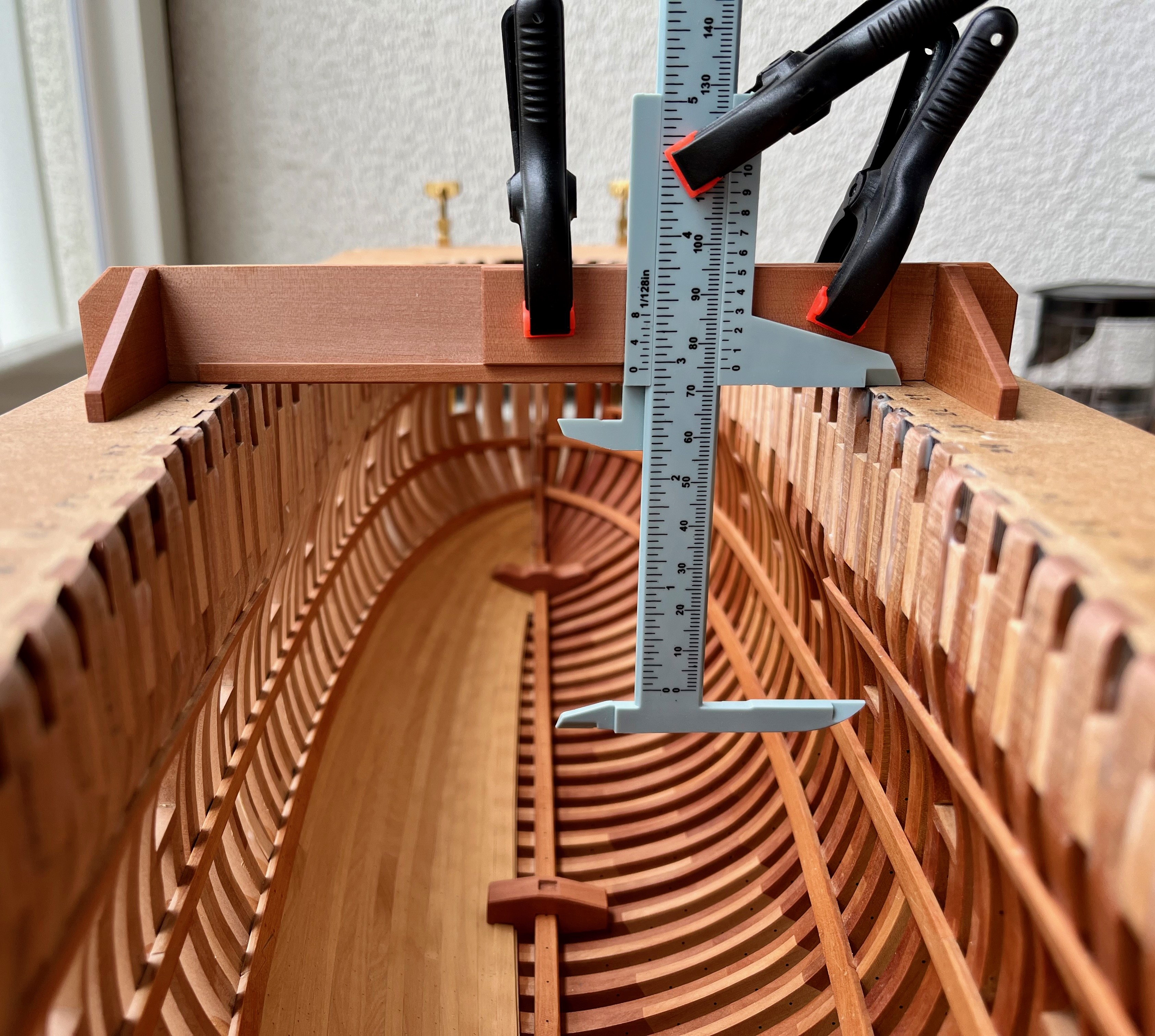
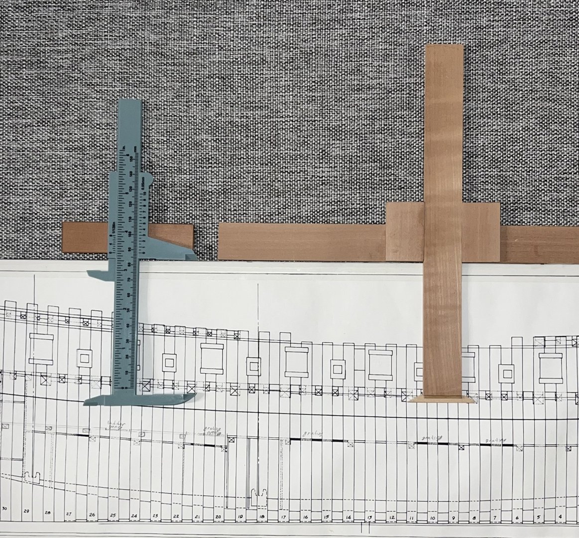
I assume you mean the vertical measurements? Then it is easier to think of it as a tool to transfer dimensions from the side plan to the hull, rather than a measurement tool. You would need some kind of a sliding gantry with a fixed height (Hahn method makes that easy since you do not need a gantry, the jig is playing its role. But you will see all sorts of aluminum profile or wooden constructions in other logs!) From that gantry you can clamp a vertical strip with pointy tip. Then I glued the side plan to some backing material, cut with an offset to match the gantry / base jig thickness. Then you can transfer dimensions from plan to model without any calculations - but by putting that cross-slide directly on the plan, locking in position and then transferring to the model: My first version was a friction fit one, just two perpendicular sticks, can't really make it any simpler: The second version was slightly fancier, but I built it because I had a loong pause and forgot that I have the simple contraption They are functionally identical.
-
Fund raising
Mike Y replied to Russ2025's topic in Using the MSW forum - **NO MODELING CONTENT IN THIS SUB-FORUM**
Had the same problem, paypal was rejecting my card that works fine in dozens of other shops and services. Or maybe my bank already considers paypal a method of choice of scammers and fraudsters... The only method that worked was a bank transfer to paypal account and then a direct transfer to NRG (not using the donation link). Maybe that would work for you? It might imply extra fees and FX conversions, but better than nothing. Contact https://modelshipworld.com/profile/19284-ferretmary1/ to get an email for the direct transfer without the donation box. -
How serious do you get about dust protection
Mike Y replied to bigcreekdad's topic in Modeling tools and Workshop Equipment
To illustrate the points from my previous post - recorded a video that shows the extent of the efficiency of this small purifier. Even large and visible particles are picked up easily, so hopefully tiny invisible ones follow even better You can also judge the noise - you can't really hear it, especially behind the dremel Sorry, no more updates on this, I promise! -
Beautiful build, subscribed with interest 😊 Looks like it is by far not your first POF build based on the quality!
-
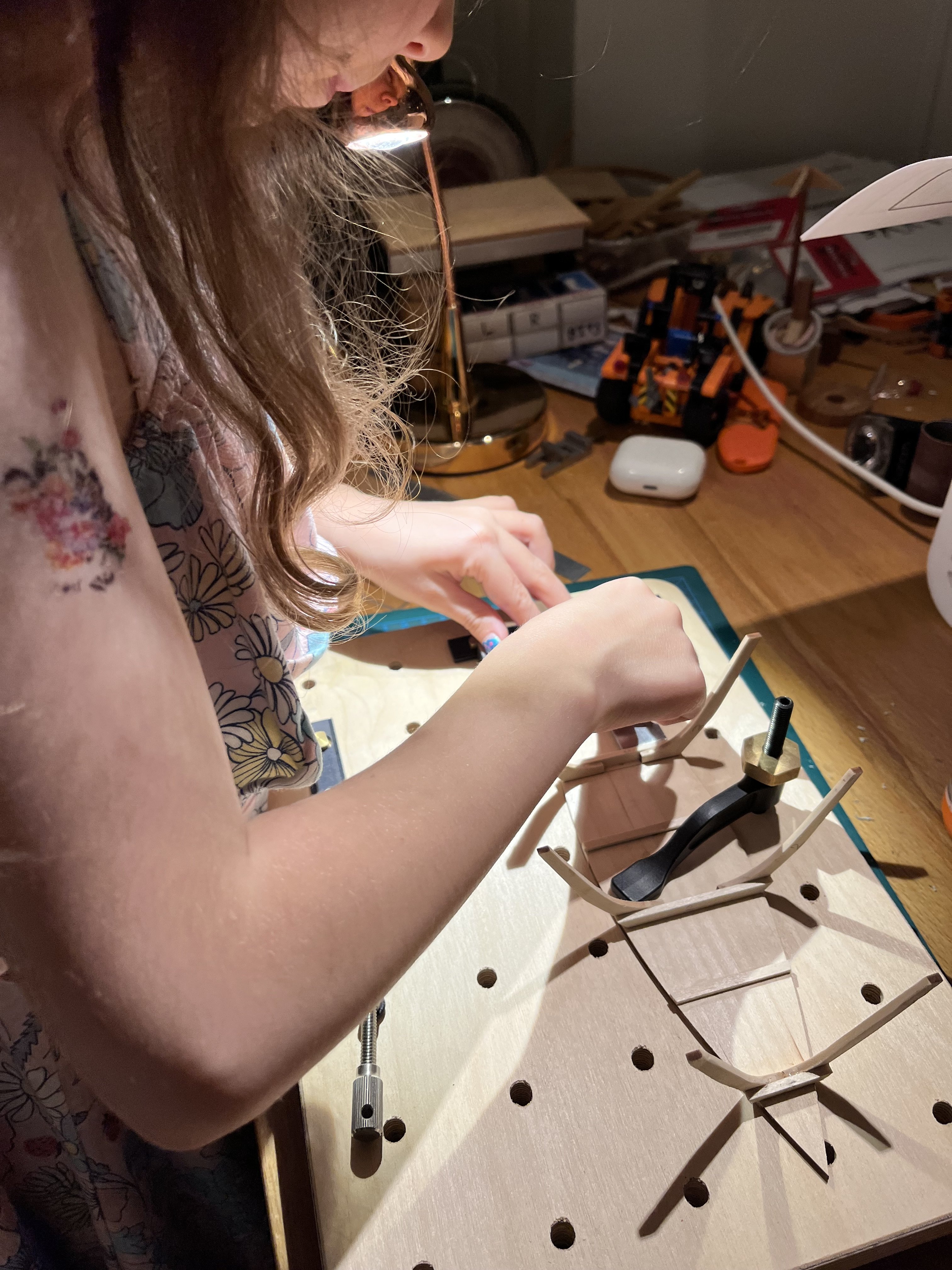
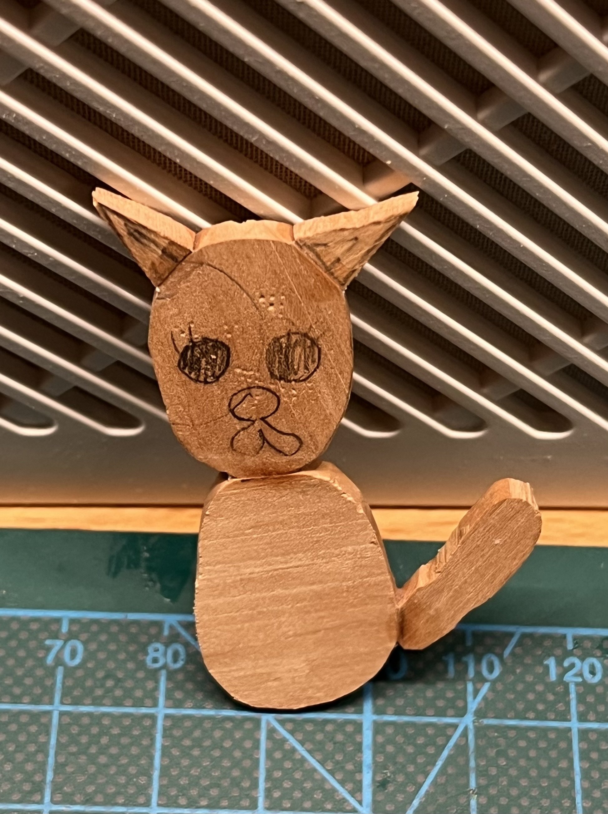
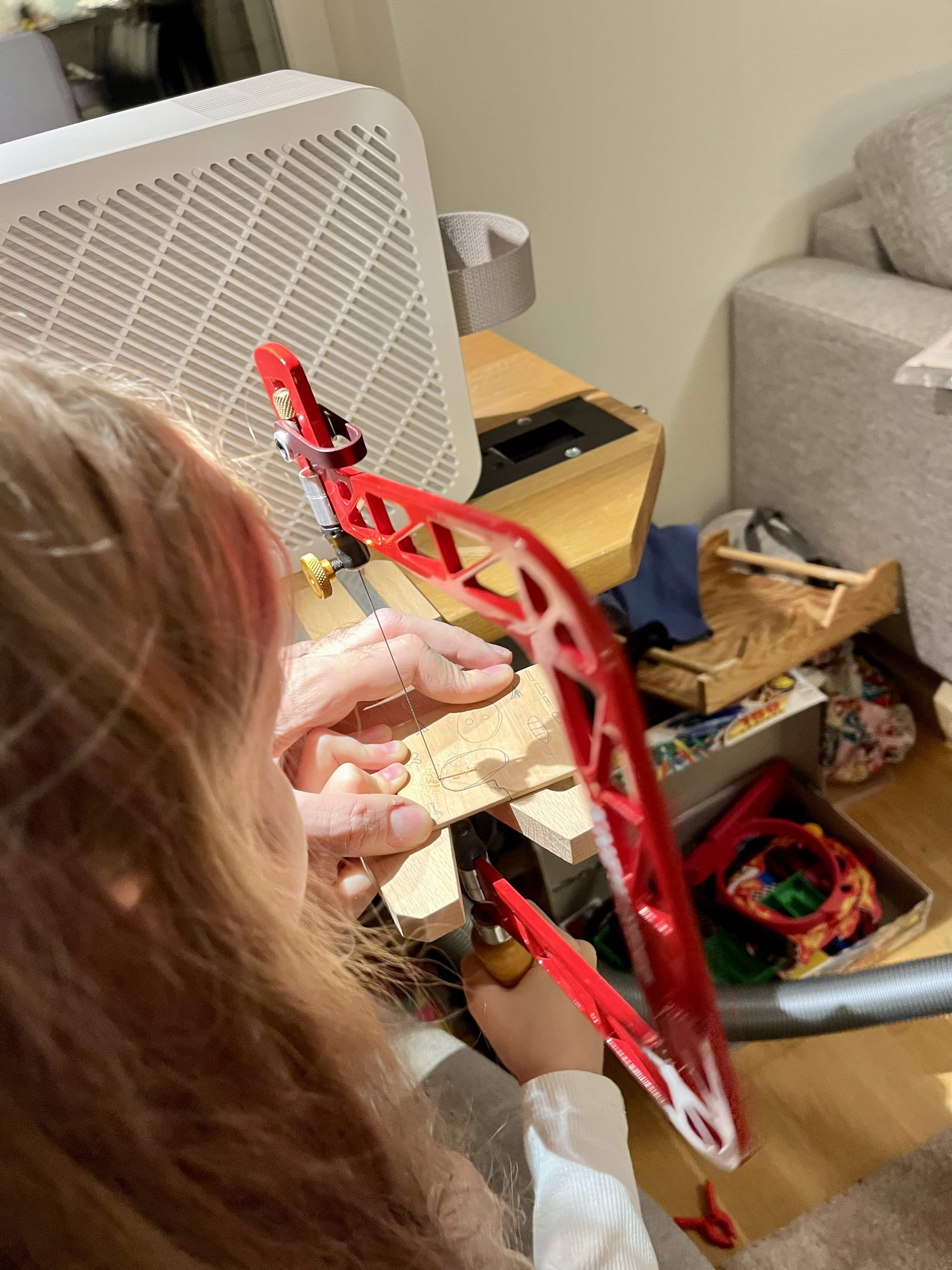
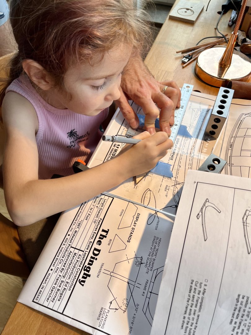
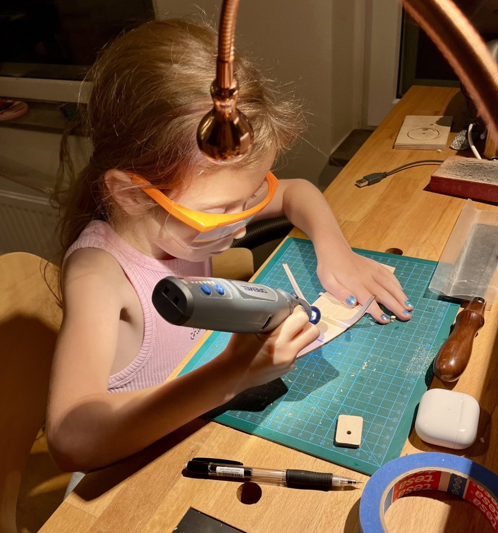
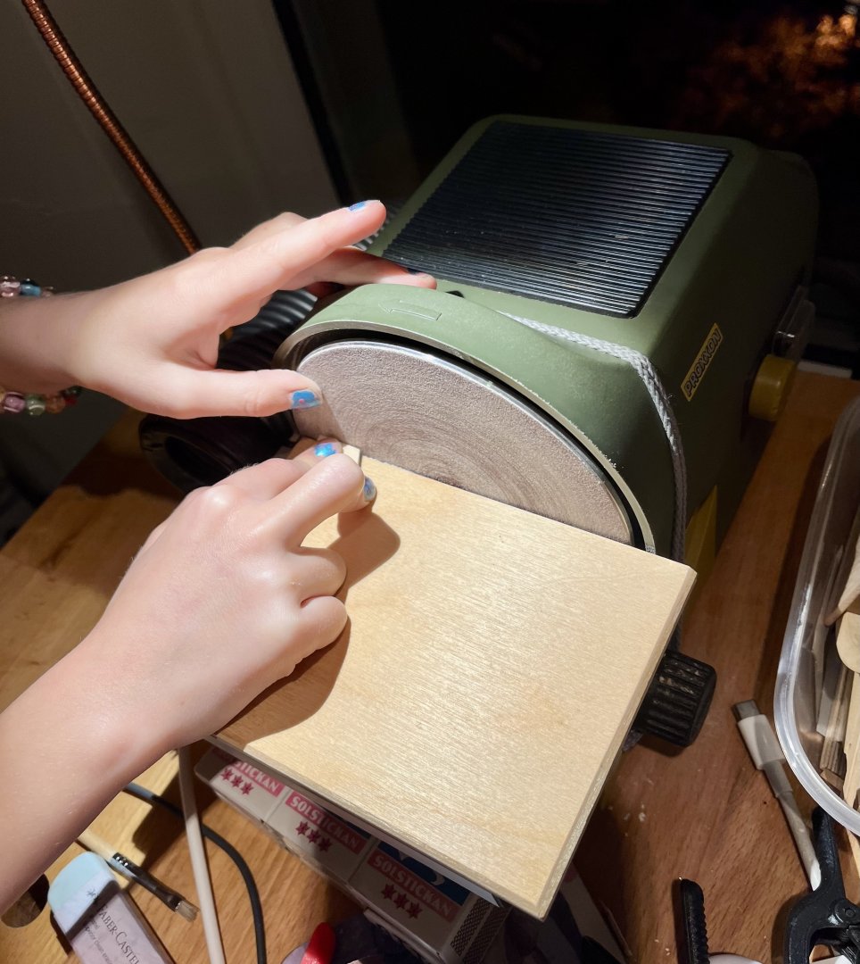
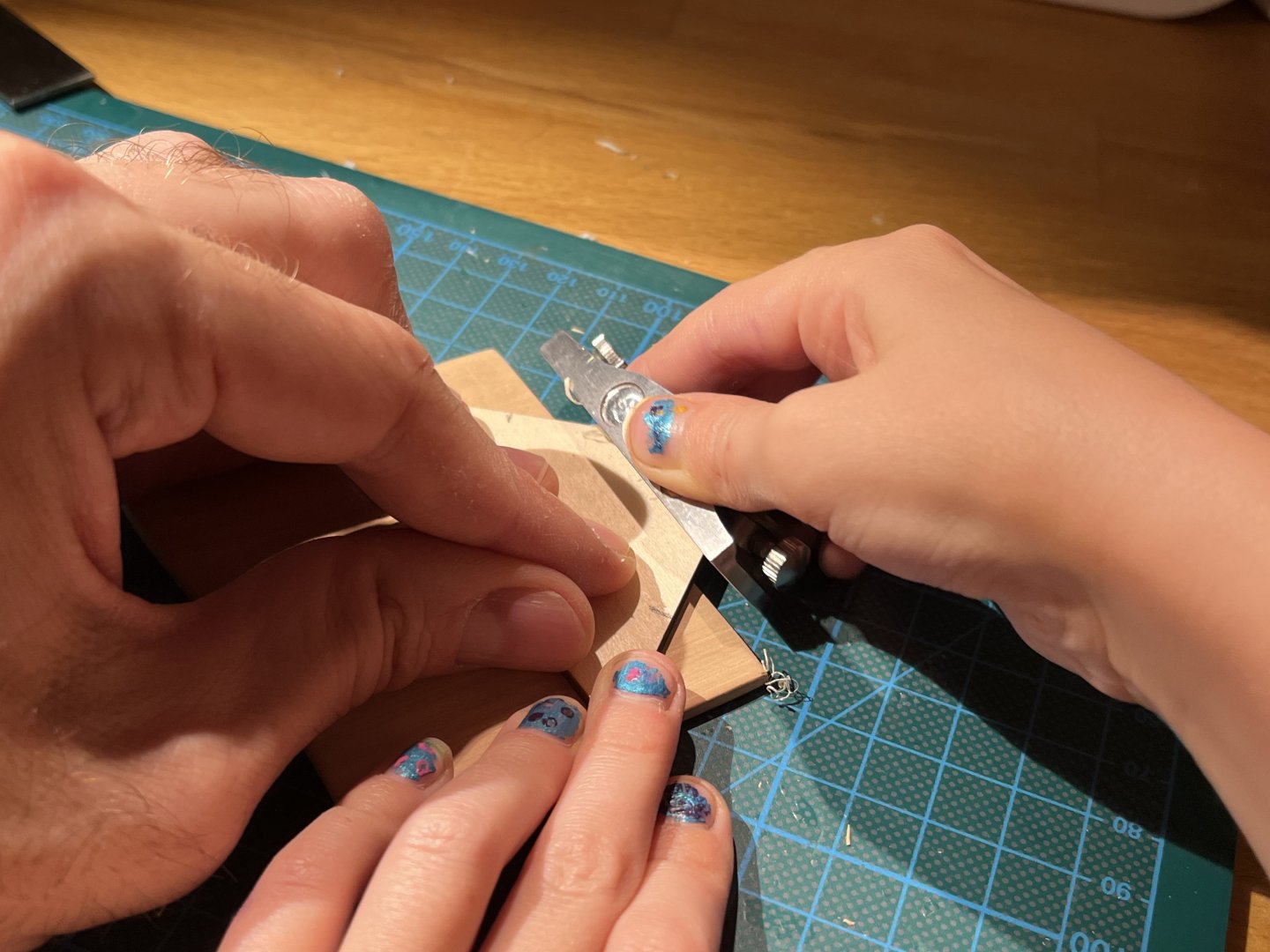
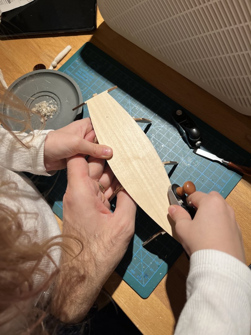
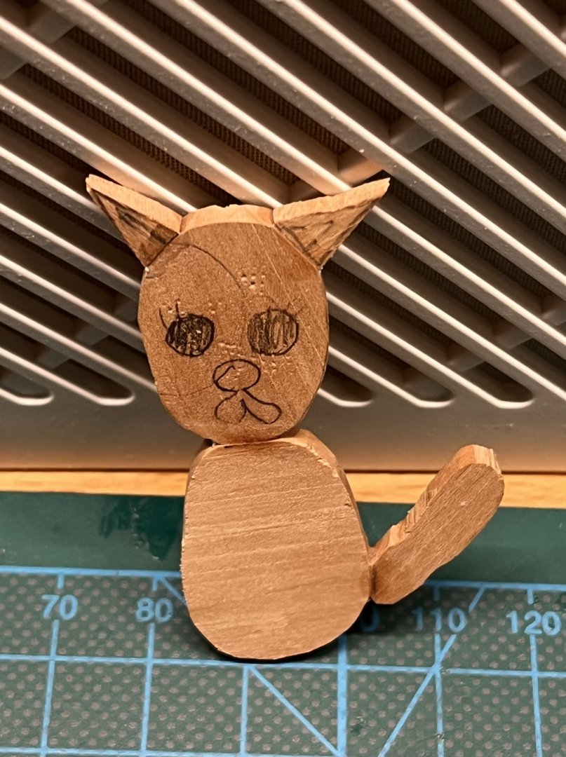
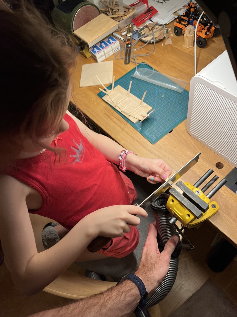
I started with both of my daughters around the age of 6 (see the Polotsk build in my signature, the youngest does not have a build log yet). It may sound young, but at that age they usually have basic precision required. Of course the motivation is different, they saw me modelling and wanted to try that too, to a large extent as a together-time, as opposed to going into the hobby purely for the sake of hobby. They were never interested in getting the final result, but wanted to try the process. Sanding wood, shaping wood - all of that was a learning curve and a joy. It is very different with plastic and not sure fiddling with plastic glue and tiny parts is enjoyable. Do not expect that the model would be completed, it's too much of a stretch. And by the age of 10-12 they have got a lot of other hobbies, so might be too late Expect that they would never finish the model, and by that age - would stop caring about finishing, but would hopefully cherish the memories you had together. Modelling for them is just an excuse to try all these new skills and spend time with their dad, while feeling a joy of building something more complex than a Lego. Surprisingly the type of a ship does not really matter, as long as it is a fairly straightforward kit where you just cut pieces, glue them together, etc. But it is really beneficial to have a kit with pre-splined planks that would fit together nicely. Skill-wise expect to teach them the very basics, that we, adults, do not even think about. Keeping the knife straight (yes, they can already use it carefuly), moving file straight, how to hold a piece of sandpaper between your fingers, how to draw a pencil line on wood, etc etc. And prepare some scrap to practice, of course. Some tools are off-limits though - no table saw, very careful with disc sander. Dremel is fine, but watch out for hair and sleeves. Band saw can be introduced a bit later. Introduce dust and eye protection for certain operations from day one, for them it is very natural and not weird if they see you do it as well. Prepare for practicing every new skill on scrap pieces, for kids to sidetrack to "side projects" like building random stuff out of cutoffs and similar foolery. It might be frustrating, but again - the journey is the goal, not the destination. Of course it is all very anecdotal and your experiences may vary, just sharing mine. Do not wait until they are pre-teens, do not start with plastic, just dive right into the wood if that is what they want. There is nothing extremely difficult in cutting and gluing wood pieces for elementary school kids. Just need supervision and patience. Some teaser pics, she has just turned 6.


- 27 replies
-
- 11
-
-

-
How serious do you get about dust protection
Mike Y replied to bigcreekdad's topic in Modeling tools and Workshop Equipment
If you put it close to the object (close enough to not be in a way of your tools and files) - with the right light angle you can visibly see how fairly large dust particles are immediately sucked by the stable airflow into the filter, away from you. I assume that the much more dangerous fine particles (the ones not visible with the naked eye) are following the flow even better It's not like the vaccuum hose sucking from one spot, but it creates a continuous movement of air towards the filter from a much wider area. So yes, it is not very powerful at all, but by putting it next to the sanded object you end up with fairly good efficiency. When experimenting you will see that the distance is crucial. Move it away - and you no longer capture particles at the source, but start filtering the "air in the room", needing large fans with much larger surface area and airflow. And it is also very quiet, so you will run it for hours, and not turn off immediately (any tool is better than the tool turned off ). You would not sneak away to sand things quietly, avoiding a loud dust collector to not wake someone up. It would be quite useless for general woodworking or sanding large surfaces - since you would no longer be able to place it close enough. But perfect for our needs I think (sanding a small part by hand or in a vise, with a part located close to the filter). Remember that it is just a replacement for a vaccuum hose, not a magic tool that solves all dust issues. This is what it replaced for me - a fiddly hose that I always need to somehow place as close to the vise as possible, it falls off, bumps around, and is less efficient on such distance, since it creates a very local suction zone, rather than a steady airflow away from me. Ofc the vaccuum is still used with power tools (table saw, disc sander, mill, etc) - anything where the dust source is fixed in place with a way to get the hose very close to the source. I still wear a respirator mask when sanding - when working close to a part with an optivisor on you can inhale dust straight from the source. None of the dust protective measures are 100% effective on their own, it is all about multi-step reduction and reducing percentages. The mask would also not be working well if you are sitting for hours in a cloud of fine dust, the vast majority of the dust must be removed away from you before it can spread around. This compact purifier is taking that role, while the mask is preventing you from breathing it in too easily. Masks are also sensitive to the proper fit, not really compatible with beards, etc.


-
Good to know! Has anyone heard back after using the Contact Us form? I used it back in October, but have received no email / confirmation back. No big deal since it is still early days, but was not sure the form is even working
-
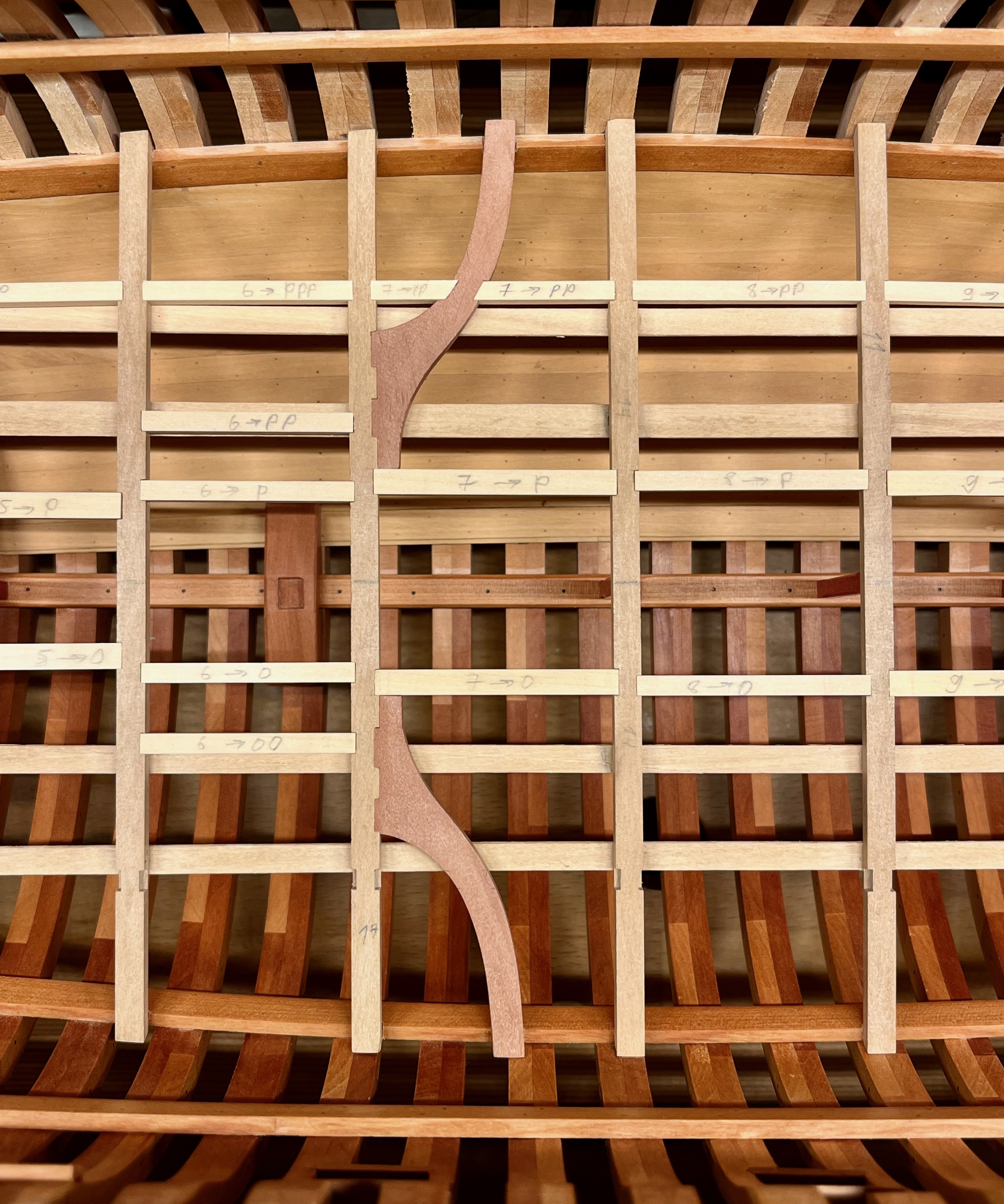
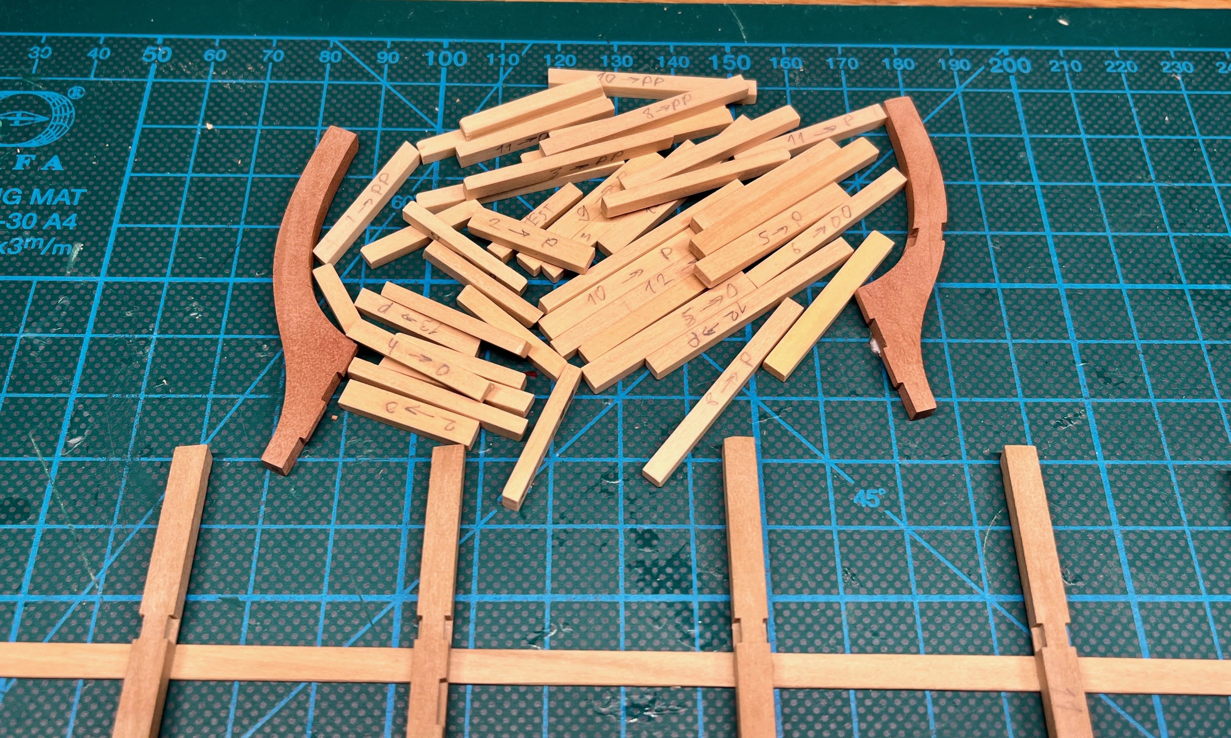
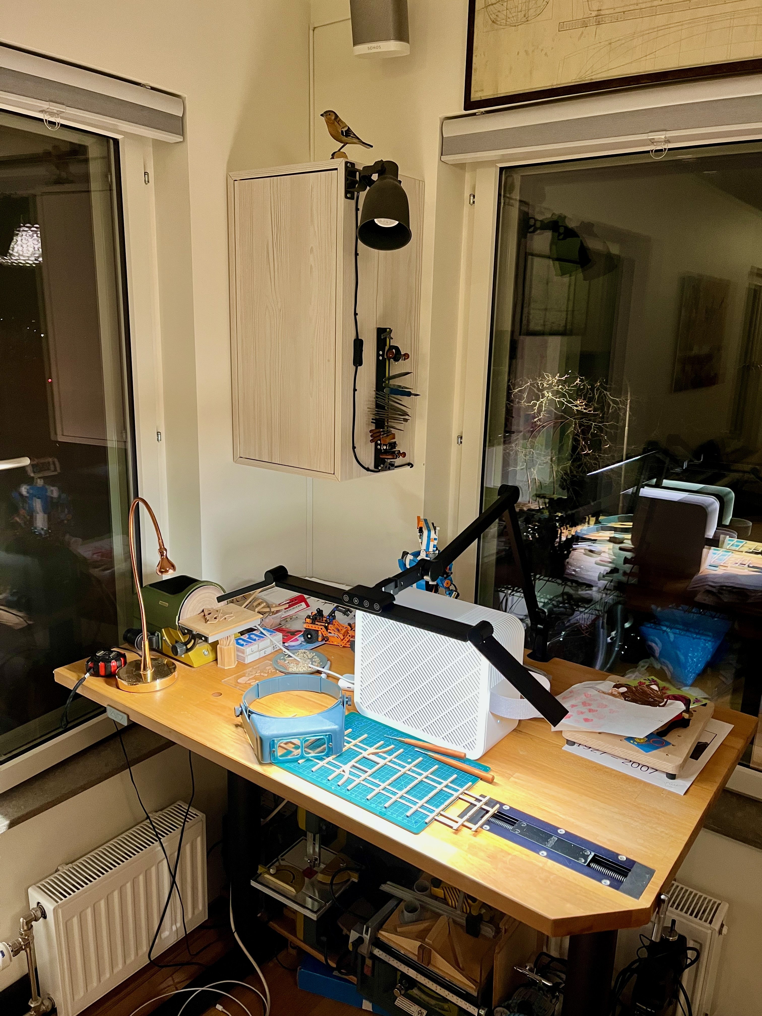
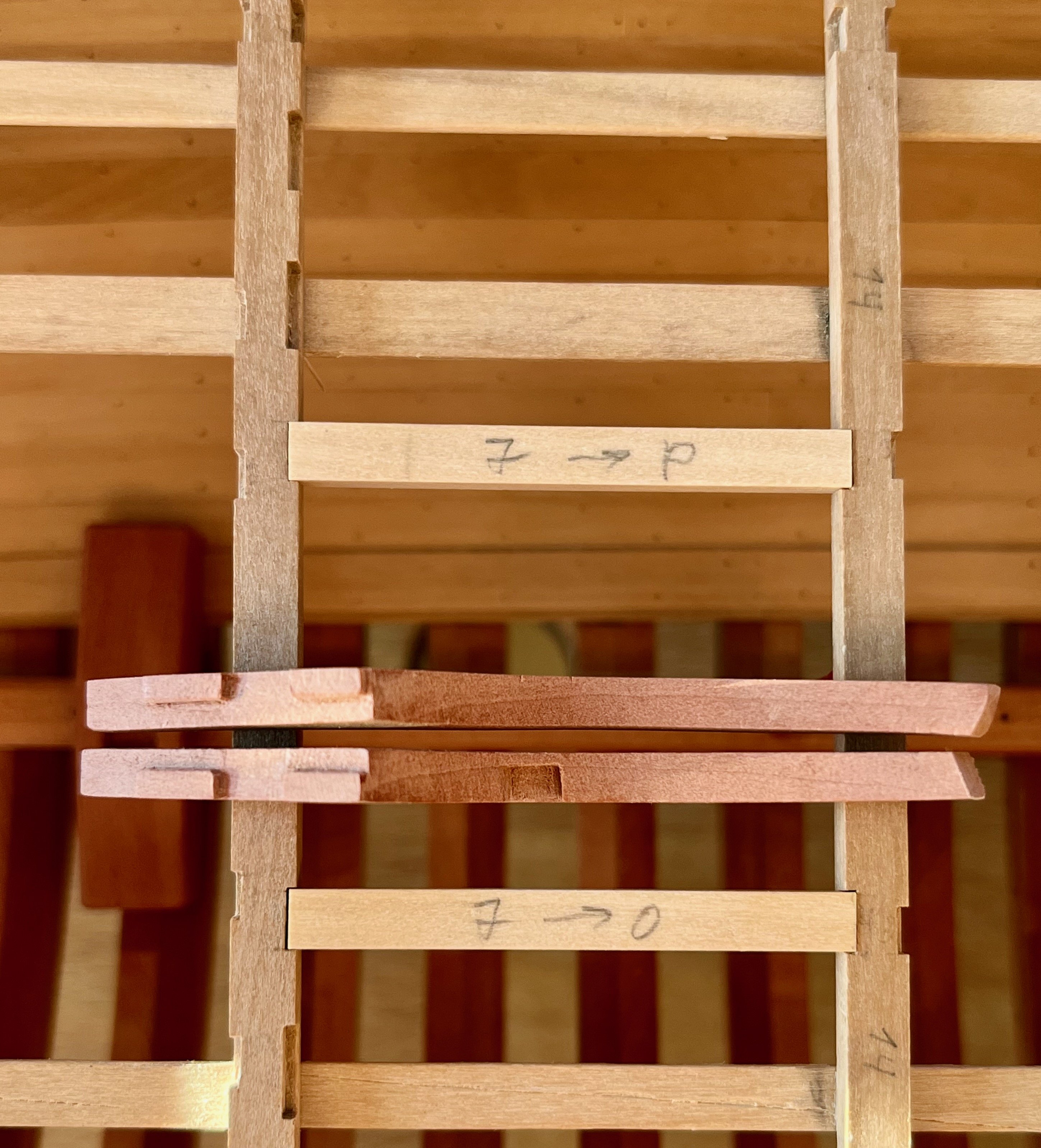
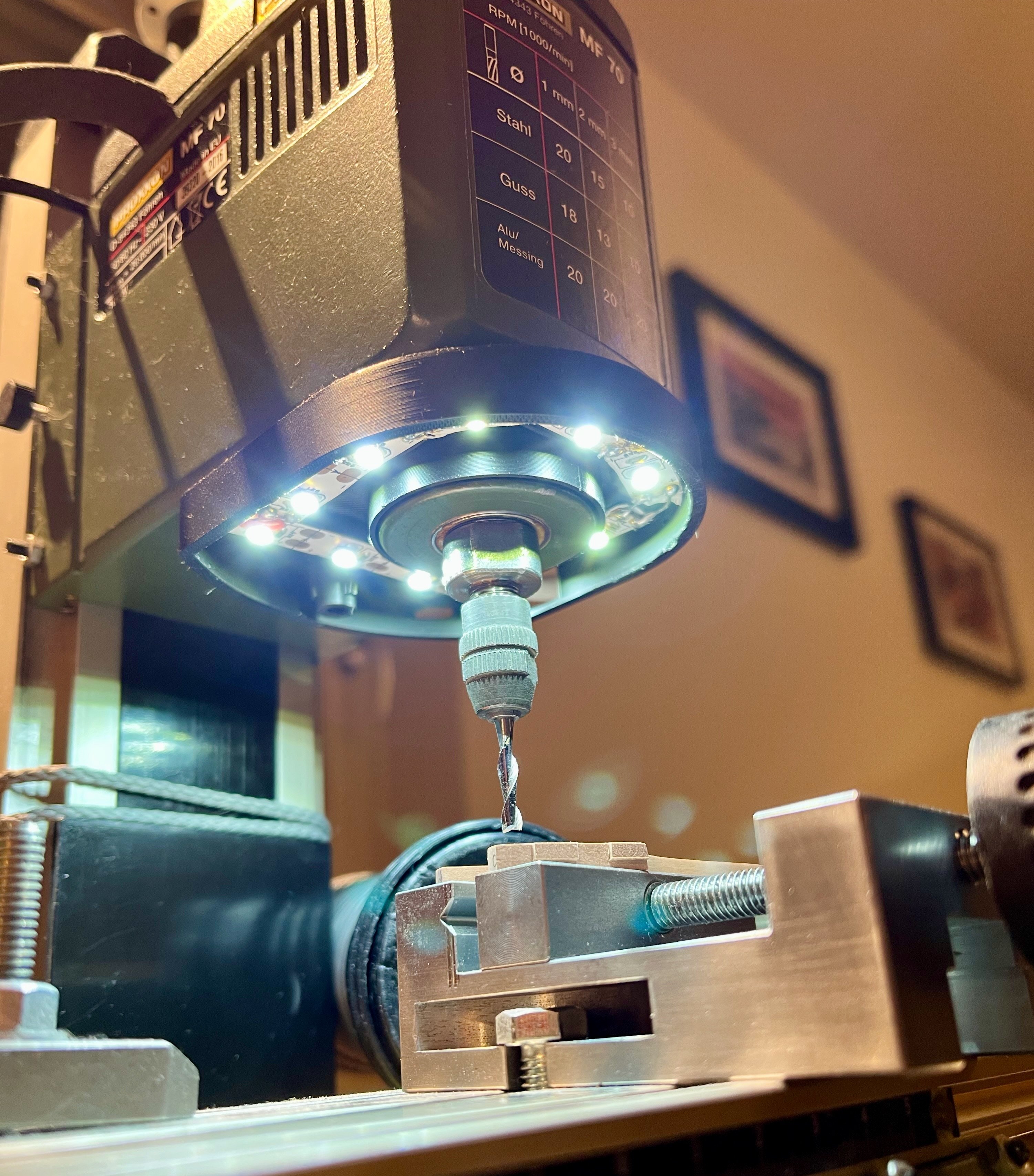
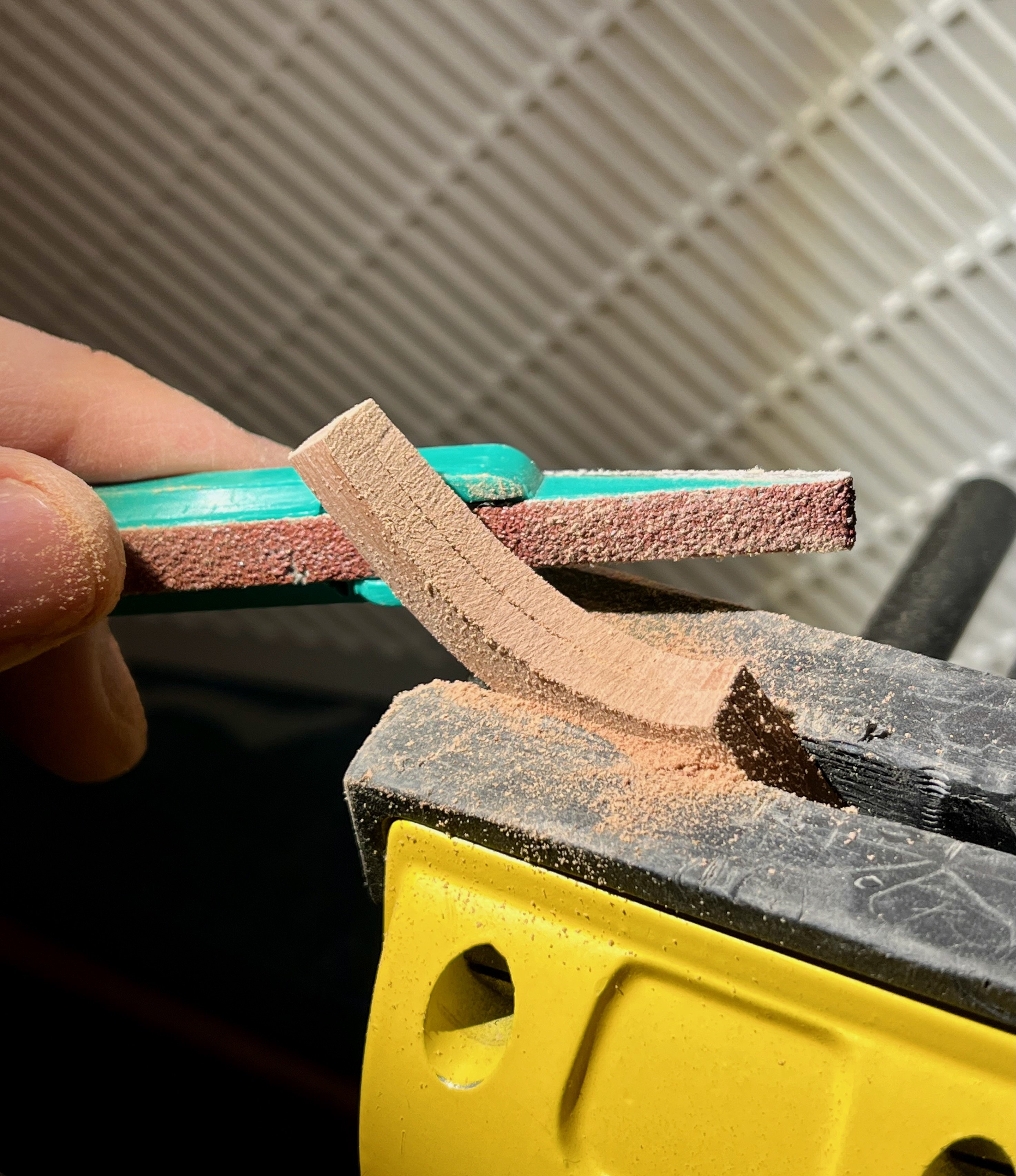
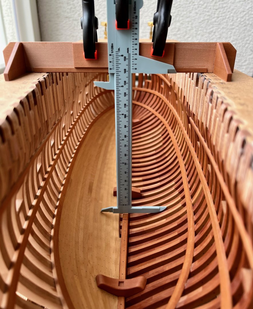
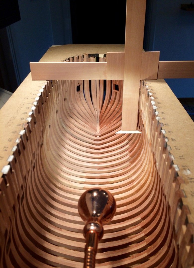
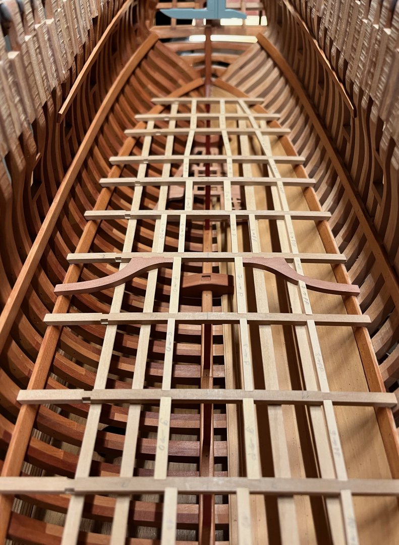
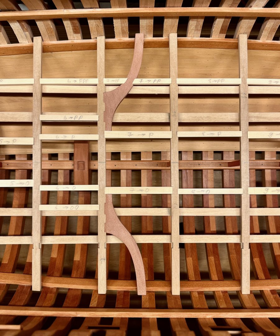
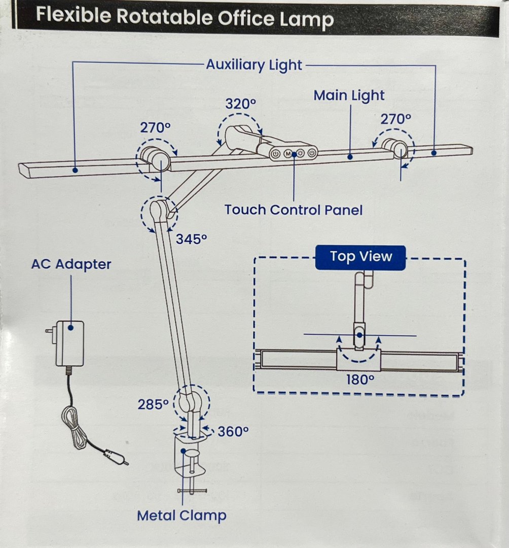
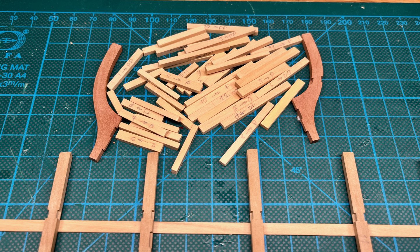
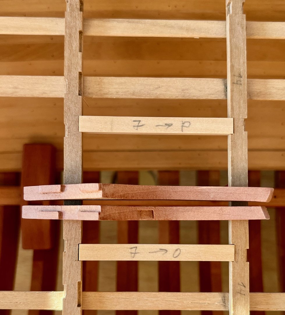
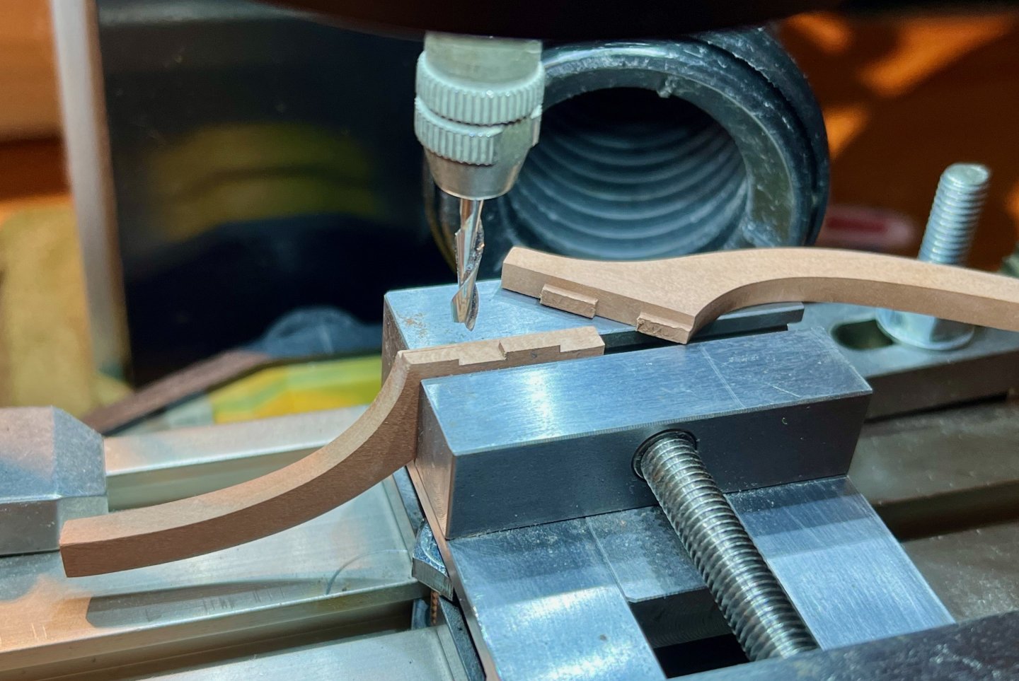
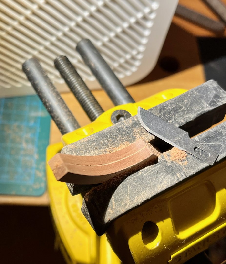
Beam arms Beautiful piece of the deck structure, was waiting for this moment for a while! Tried to use my fancy Vallorbe files, but the easiest way to shape these was a coarse sanding stick followed by a quick pass with finer grit. Then scraping to flatten the edge - and you get a fine finish with very little effort. Just need to be mindful of grain direction to not scrape against the grain Joints are milled, of course. That kind of precision work is where a mill really shines! Speaking of milling - I added a crudely made light into my Proxxon MF70. It is based on strange 3d model that I found online, trimmed off all the strange bits and glued in a cheap USB-powered LED strip, cut into short pieces and soldered with dodgy cuts of solid wire. It works, excellent value for money! Can definitely recommend to spend time on making your own, one of these "I should have done that sooner" moments. There is nothing off the shelf that you can buy for MF70, only some dim LED ring on ebay for way too much money. In other LED updates - got a lamp similar to the one recommended by Chuck (amazon/aliexpress, 50 USD, likely same manufacturer, but smaller size). It is awesome! Angled "ears" allow you to illuminate the piece from multiple angles, which is very handy when carving notches. The light quality (colours, flickering) is very good in my unscientific tests, and makes for a good photo light. The adjustable arm is solid (joints not too tight, not too loose, very elegant), and it is not an eyesore. A lot of adjustability and tilting angles. More than enough brightness, and the adjustable colour temperature is handy. The only downside is that the touch controls are facing forward, so I touch them by accident way too often The arms are slightly curved to follow the deck shape. I over-curved them at first, but luckily had enough margin to smoothen them with some battens. The resulting curve is very gentle: And here they finally glued in. Actually the first part of the deck that is now permanently glued in place! I am avoiding the final glueup as much as possible, feels much better when everything is dry fit Now I have a pile of carlings ready for installation And here they are all in place! Notches on the exposed side are left empty to avoid obstructing the view. I might put some carlings into them later. They needed more care than the non-empty notches, since you want all notch surfaces to look smooth and pretty, no chance to cover them with a carling later on. So I was cutting a smaller notch and then make a few final cuts once it is done, cutting off any tear-out. That concludes the carling phase, next in line are the lodging/hanging knees and ledges!


- 969 replies
-
- 24
-
-
-
- hahn
- oliver cromwell
- (and 1 more)
-
The intrigue is on - how exactly are you sharpening them? 😊 I tried the Veritas burnisher/sharpener, but had little success with it..
-
Impressive! You managed to preserve that smooth "corner" in the transition between the flat bottom and angled sides, creating a very beautiful line It would have been too easy to loose it during the fairing process!
-
It's incredible what a bit of sanding can do! If only you could have that magic wand in other areas, not just woodworking Very nicely done, waiting in suspense for the post-finish photos
- 233 replies
-
- 1
-
-
- Model Shipways
- constitution
- (and 5 more)