HOLIDAY DONATION DRIVE - SUPPORT MSW - DO YOUR PART TO KEEP THIS GREAT FORUM GOING! (Only 72 donations so far out of 49,000 members - Can we at least get 100? C'mon guys!)
×


bhermann
-
Posts
548 -
Joined
-
Last visited
Content Type
Profiles
Forums
Gallery
Events
Everything posted by bhermann
-
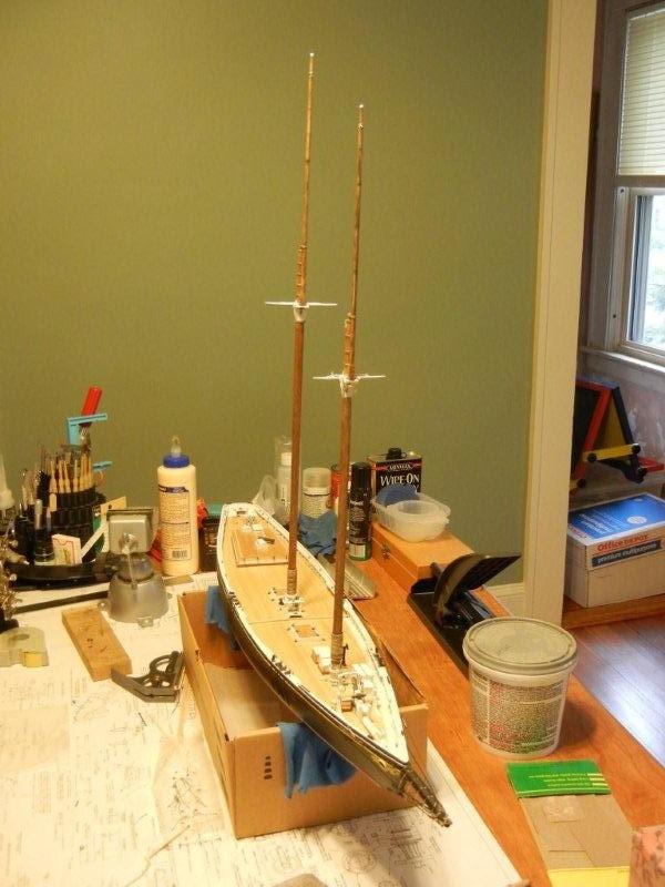
Thanks, frodeo. It has been fun to go back through all the old photos and recall the challenges and successes so far. I look forward to seeing the work on your restart. Elia - I am happy with the way the masts turned out... if I had to do it over, I might look for something just a shade lighter and a little redder. There's just no pleasing these model builders Gerty - thanks for the kind words. I have been enjoying your Willie L Bennett log. I like that the construction is more like the real thing than what I have been up to. Bob
-
Thanks Marc for taking the time to re-do this. I love the lines of these ships and will be looking forward to updates as they come. Bob
- 525 replies
-
- 1
-

-
- cutty sark
- mantua
- (and 2 more)
-
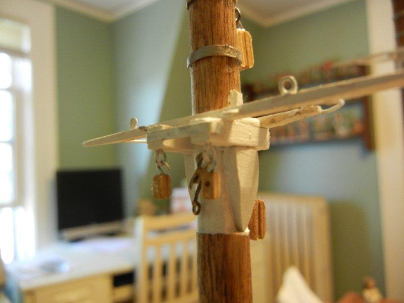
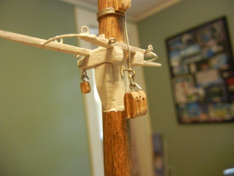
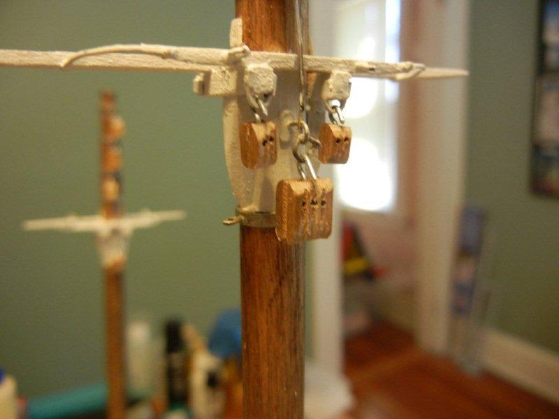
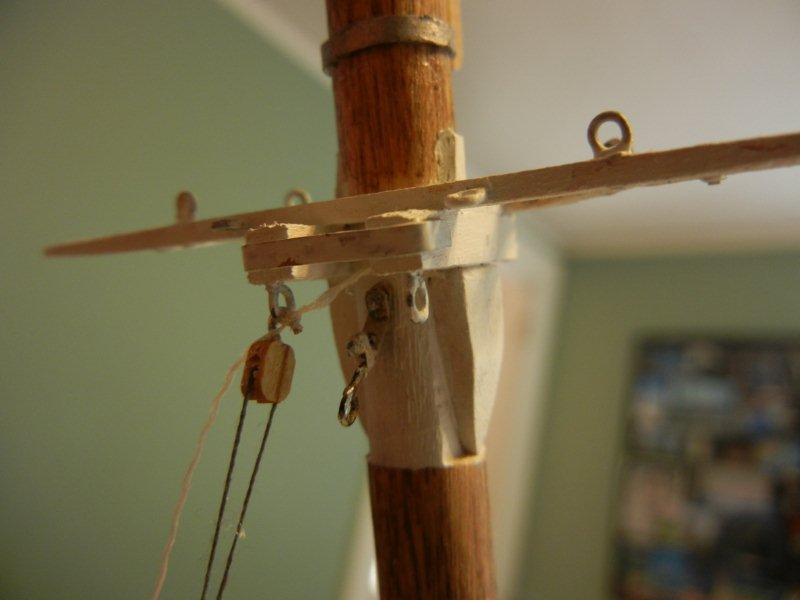
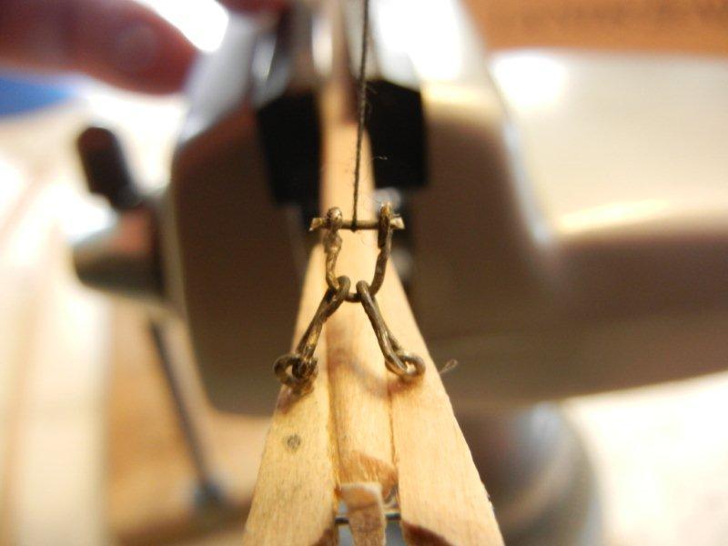
I added some blocks and other hardware to the trestle trees. First the foremast. Fore side Aft side main mast aft side A couple of shots of putting tension on the line while mousing a hook. Bob
-
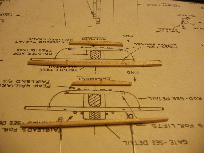
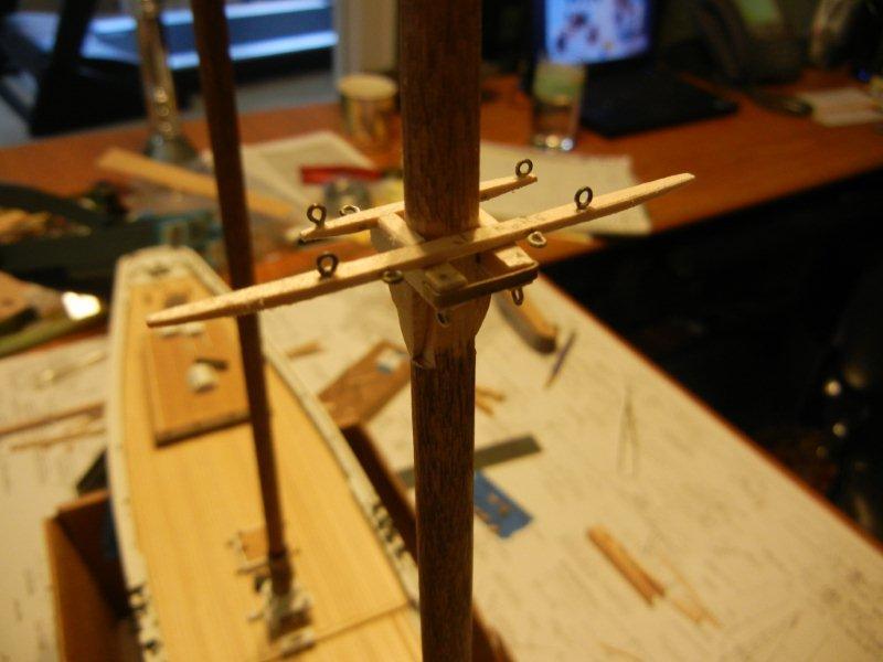
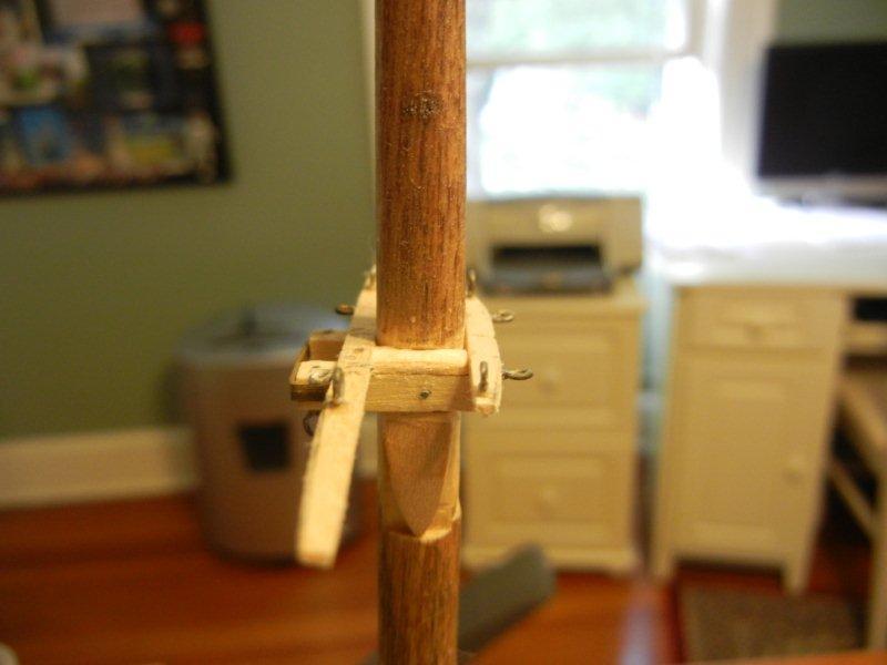
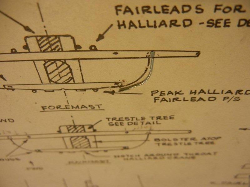
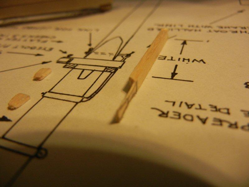
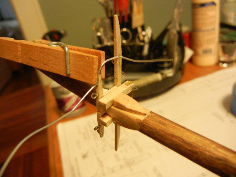
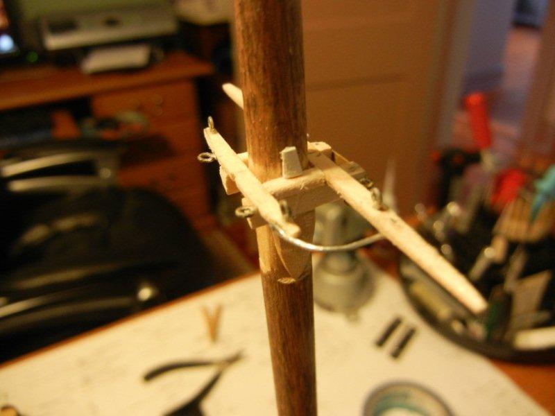
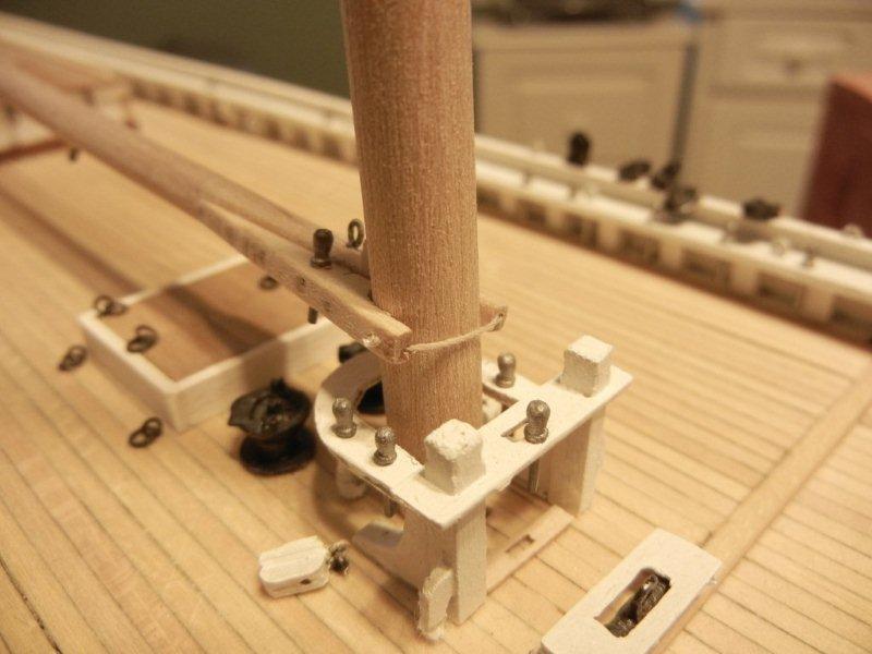
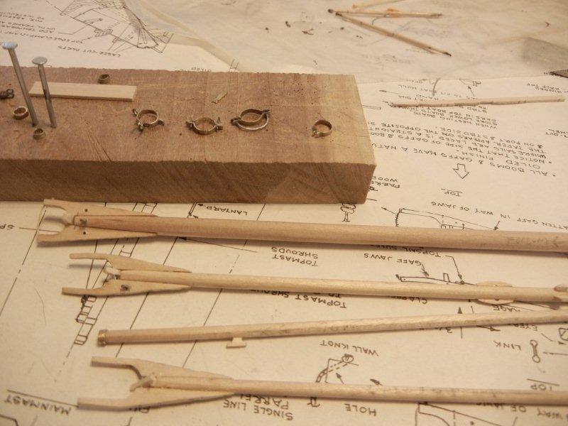
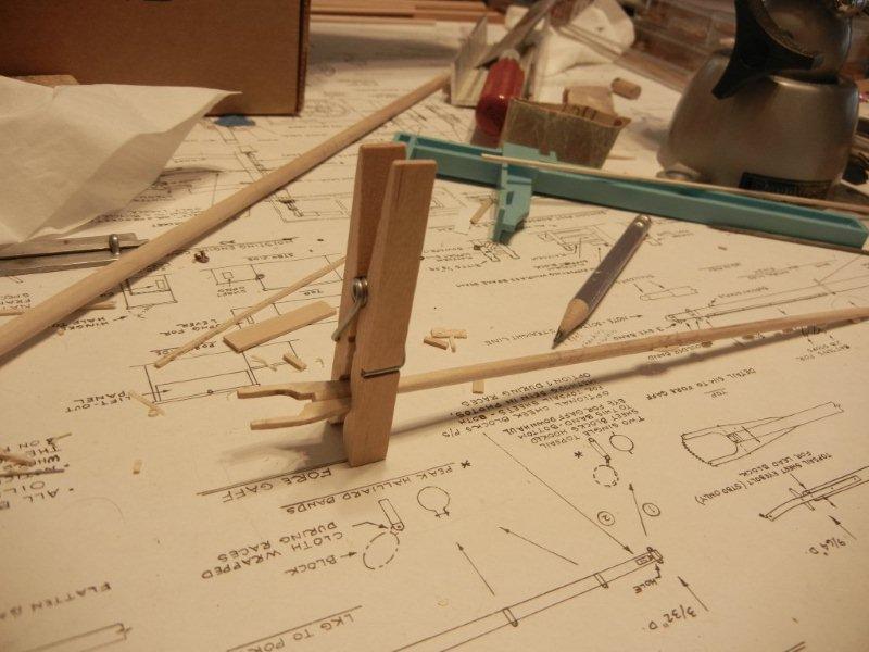
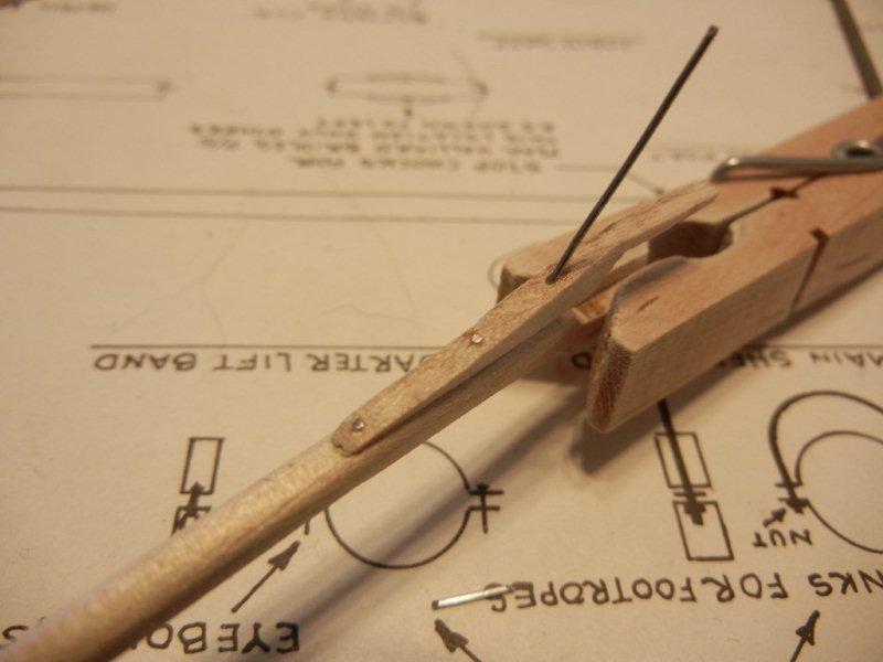
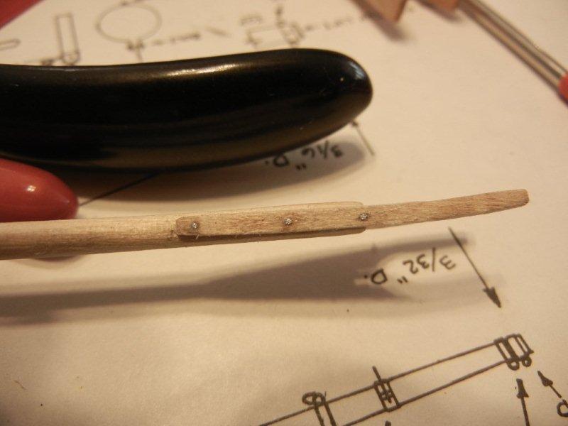
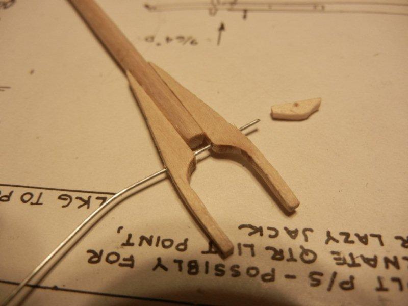
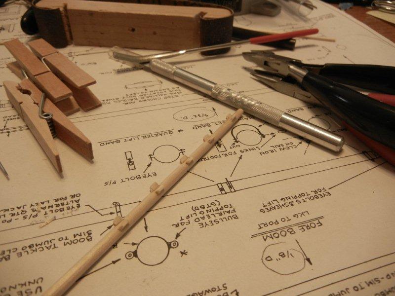
And now for some work on the trestle trees. First up is prepping many of the parts. The wooden pieces are cut to length and shaped according to the plans. Eyes are shaped and holes are drilled for fairleads. The cheeks supplied with the kit are a bit shorter than the plans so I added some filler to the top and tapered them toward the bottom. The mast is flattened to take the cheeks. Checking the width with the calipers here. There is a metal rod that runs between the cross-trees. I flattened the ends to take a bolt by squeezing it in the vice. The wood pieces are glued in place. I have added the gate at the front that will support the topmast. I added a bit of wire in a hole drilled into the mast for additional support. There are bolsters that sit above the trestle trees that will take the load of the shrouds. Here they are being shaped. The pair on the left were my first attempt which turned out too fat. I then recalled Russ's "make stuff on a stick" approach and did the second pair. It was much easier to sand them to the correct thickness before paring them off the stick. The metal support rod went on next. I drilled holes though the flats and through the cross trees then glued and clamped. The first rod is installed - the rest were done the same way. The bolster has been installed as well. Bob
-
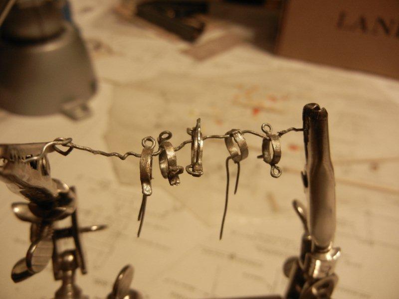
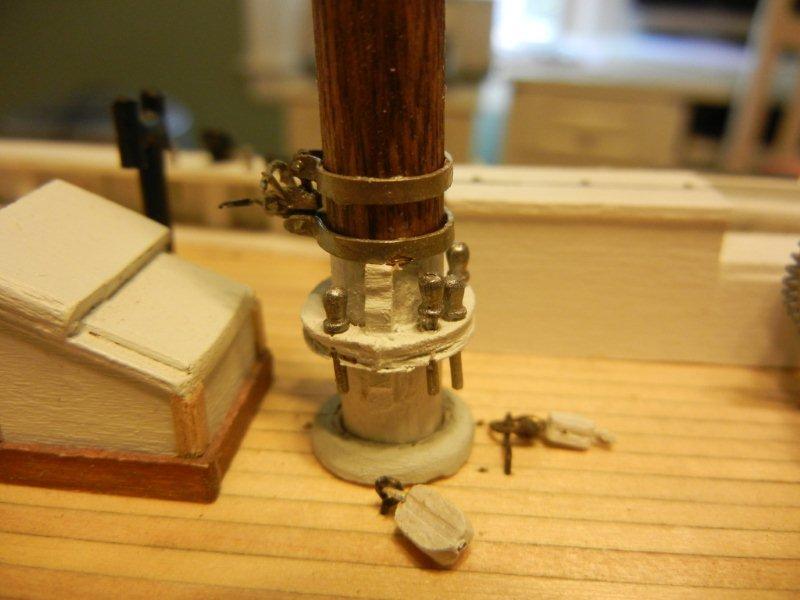
Russ - thanks for your words of encouragement. I always appreciate your visits. About the cleats, it would be best to use some sort of anchoring mechanism going forward. I may not up up to drawing bamboo dowels, but there are plenty of round toothpicks in the world . Per - I am looking forward to the start of your Bluenose as well * taps foot * Alfons - I am not moving so fast after all - what you are seeing is 5 1/2 years of build log being recreated for MSW 2.0 As a general note: I decided (after mixed results with Blacken-it - and a look at many of the photos on the Nova Scotia website) to go for a "galvanized" look for most of the metal work. This photo shows some of the metal work hung out to dry after receiving a coat of Model Masters "Steel" paint. Bob
-
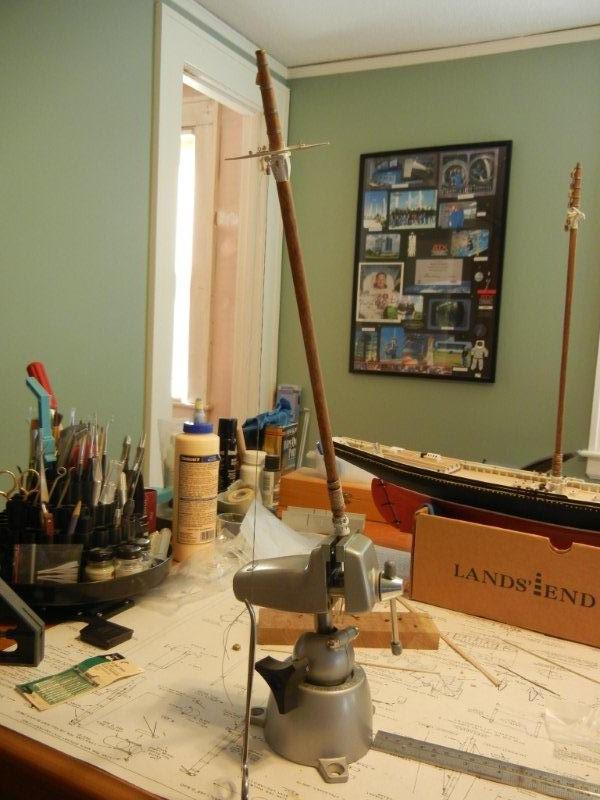
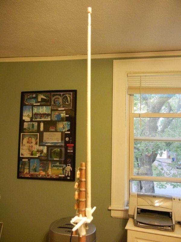
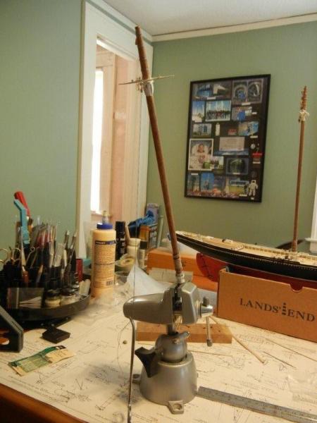
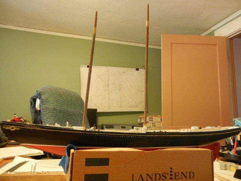
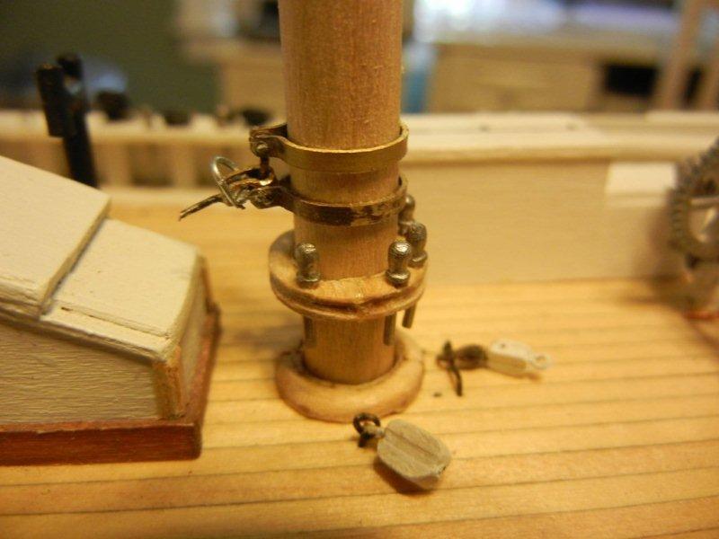
Prepping and staining the masts. First the section where the trestle tress will be installed is masked off. Both masts are put into the vice and the pre-stain conditioner is applied. Fifteen minutes later the excess is wiped and stain is applied. The masts drying in place. The idea behind staining the masts was to give them the look of being oiled (slushed) to allow the mast hoops to slide easily. I used Minwax pre-stain and walnut stain. The base of the main mast: And again after gluing on the guard (aluminum foil glued with PVA). The fore mast after staining. Bob
-
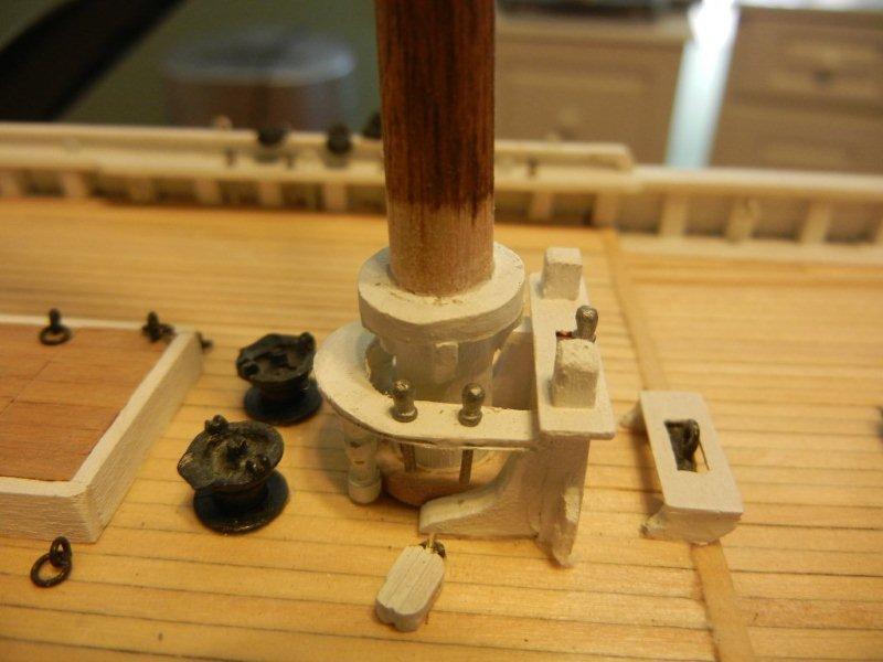
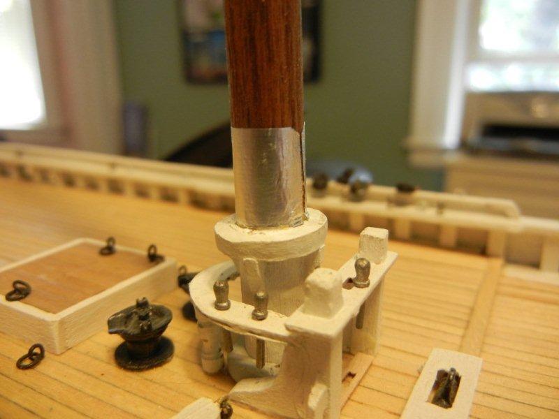
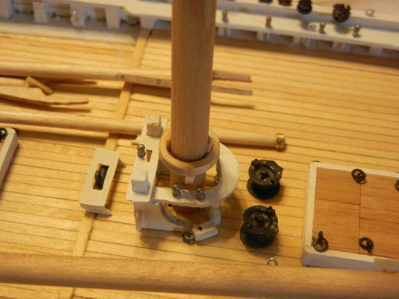
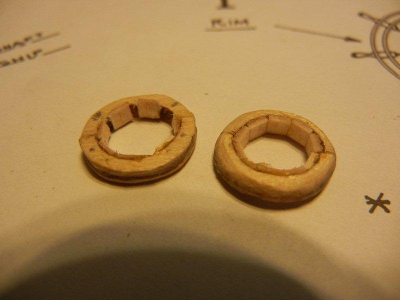
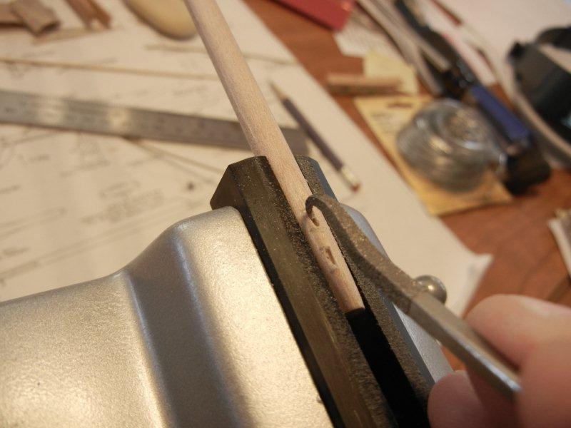
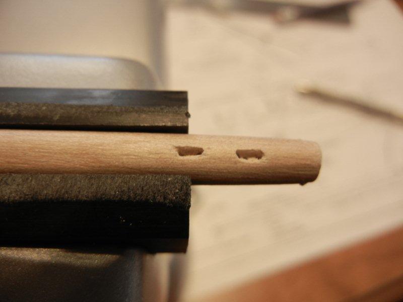
Now to the masts. The main mast requires a boom rest and the fore mast gets a pin rail. Construction of both is similar. I stared by positioning the chocks under the rest. The tape is used to mark the height for gluing. The kit supplied parts for the boom rest are a bit too wide. So i filled the inside with wood pieces, used filler to smooth them and filed the inside diameter to shape. The main mast boom rest completed and painted, mast hoops resting on it at the moment. The fore mast ring gets holes drilled for belaying pins. Above the ring you can see the mounting for the fore mast boom. Bob

-
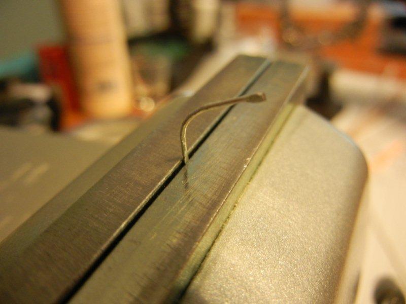
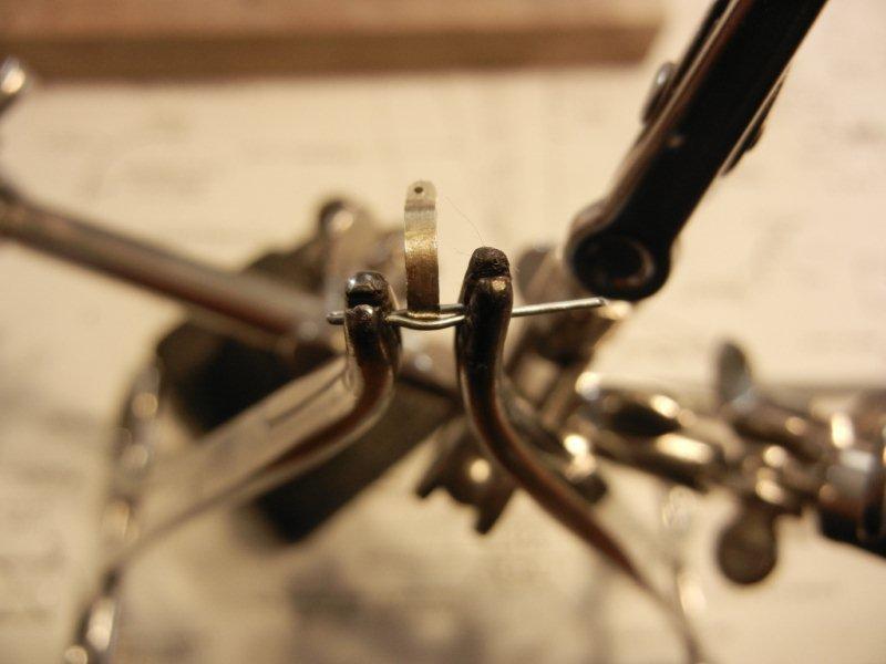
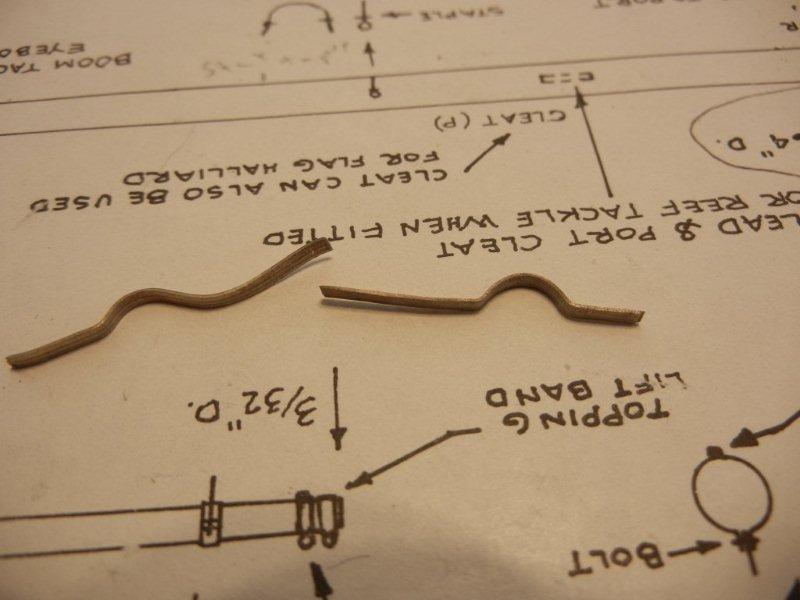
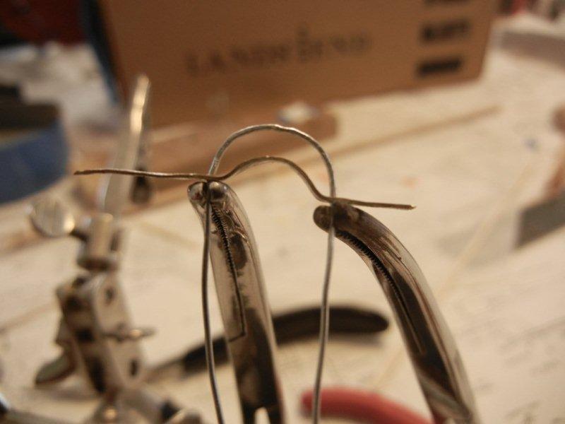
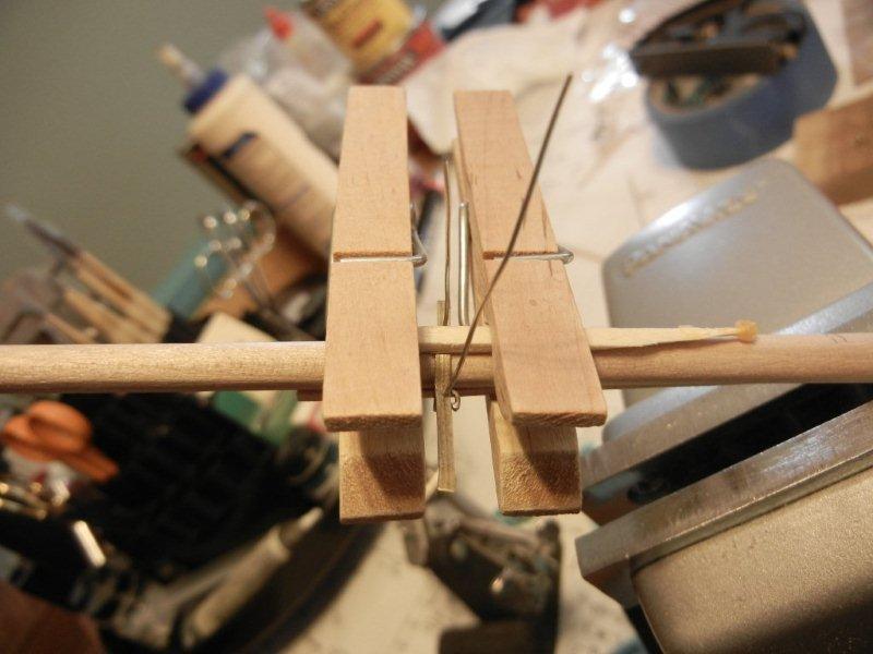
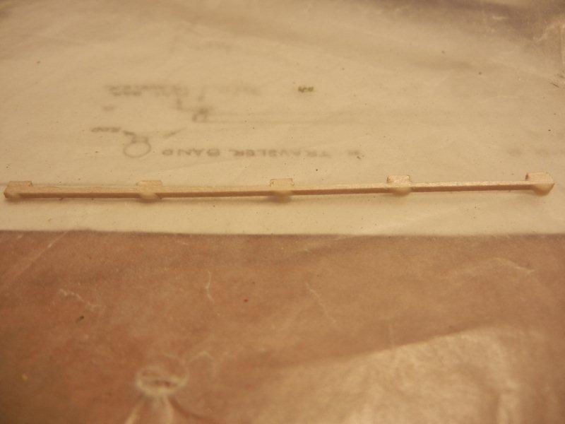
Some of the bands required simulated hinges. Here's how I did them. Originally I tried gluing a piece of wire the the band but it did not hold up to trimming and filing very well. So I decided to solder the wire in place. I folded the wire so it "clamped" over the band and then used two hemostats to hold it in place for soldering. Then I cut the ends loose and filed the remaining piece of wire. Here is the final result. The main boom has a couple of sheaves built in at the aft end. I started with the idea of making working sheaves. Drilling holes at the ends of the sheave locations was where I started this. I then started to carve away at the material between the endpoints with a rasp. After going at that for a while, I decided I liked the look well enough and stopped after carving some of the material. Bob


-
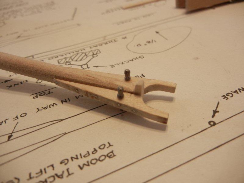
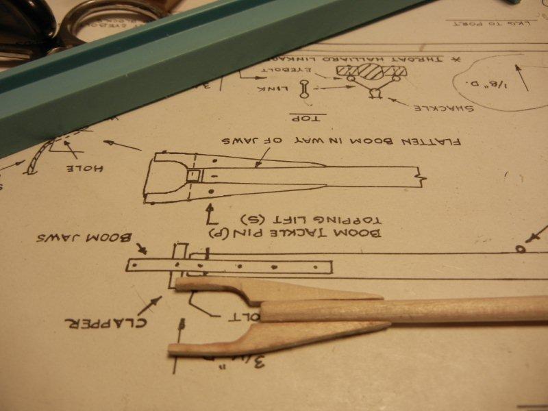
Next up, I started on the main boom. It has a different set of hardware than the gaffs after the initial shaping is done and the jaws are added. First a pair of belaying pins are put into the jaws. A cleat is added on the port side. I didn't pin it initially but I knocked it off enough times that I added the pin later. Gluing and clamping the cleat. and after install and shaping. You can see that I mark top and forward directions - otherwise I'd forget.. The main boom uses a parrel rope, but no beads. As there is no need for it to run up and down the mast, that makes sense. There is a band with a bail - this was a bit complicated for me. I started by wrapping the top and bottom pieces over the boom. The two pieces are clamped together while drilling the holes for the bail. Then the bail is soldered to the bottom of the band. The top of the bail is them placed over the bail, a piece of stripwood is placed over the band and clamped with clothespins, and glued in place with CA. After drying the whole thing is removed, the edges are roughly clipped, then finish filed. Here are several of the bands that will be installed on the boom. And in place on the boom. Bob
-
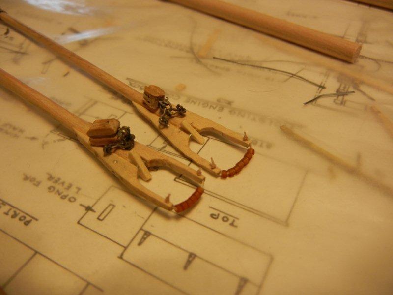
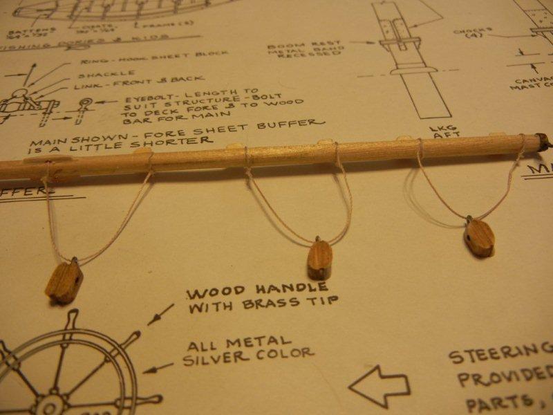
My most recent work (which means I've been working on the main gaff for over a year ) was to install a block on the underside of the gaff jaw. The topsail sheet will be run through this block en route to a belaying pin on the starboard side. This pretty much finished up the main gaff. There is one more block for the topsail sheet at the upper end of the gaff but the only thing left to do there is to mouse the hook. The fore gaff has much the same hardware on it except the blocks for the peak halliard are attached to bands rather than bridles, and there are two sets of blocks for the topsail sheet as it needs to be able to be set on either side of the main topmast stay. Bob
-
Nicely done, Wayne. Seems like a nice quid pro quo to me . Now let's see some progress! Bob
-
Coloring Basswood
bhermann replied to JPett's topic in Painting, finishing and weathering products and techniques
I echo Russ's observation. The pre-stain conditioner does a good job of preparing the surface and is formulated for that purpose so it does a better job than sanding sealer. I used it for the masts on Bluenose and was very happy with the result. When I get to that point in my log re-build, there will be some photos showing the process. Bob -
Wayne - it may be time for a mutiny - I don't know if it's fair to give us this tease and then not start on the build. I am looking forward to when you can get this build under way. Bob
-
Thank you, Gil, for rebuilding this log. Your build is truly a treasure and to have lost it would have been a blow to our hobby. I guess none of us should be surprised by what we read in Johns post, it is nice to have some of the details filled in. My first recollection of your work was when you were working on Victorys gunport lids. There was a side by side photograph of the model and the real ship. I was amazed at the time that it was impossible to tell from the photo which was which, The level of precision and detail in the build is inspirational and I will continue to follow your work closely. BTW, I have lifted your splicing technique - it gave me a heads that there was actually a way to do rigging work that looked authentic and was accurate. I will continue to follow along here as you approach the completion of a very fine piece of work. Withe great appreciation and respect, Bob
-
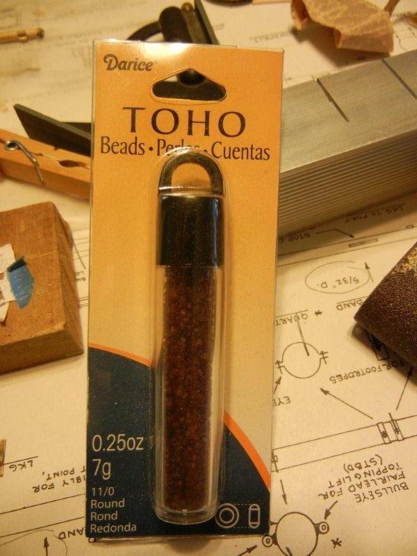
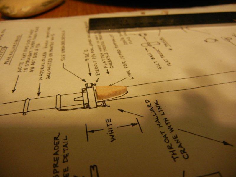
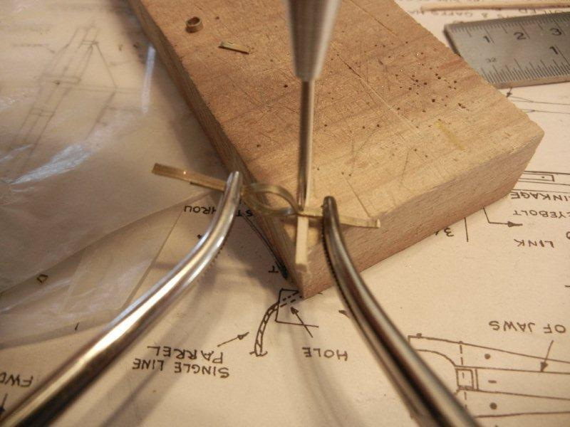
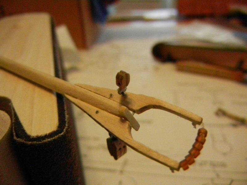
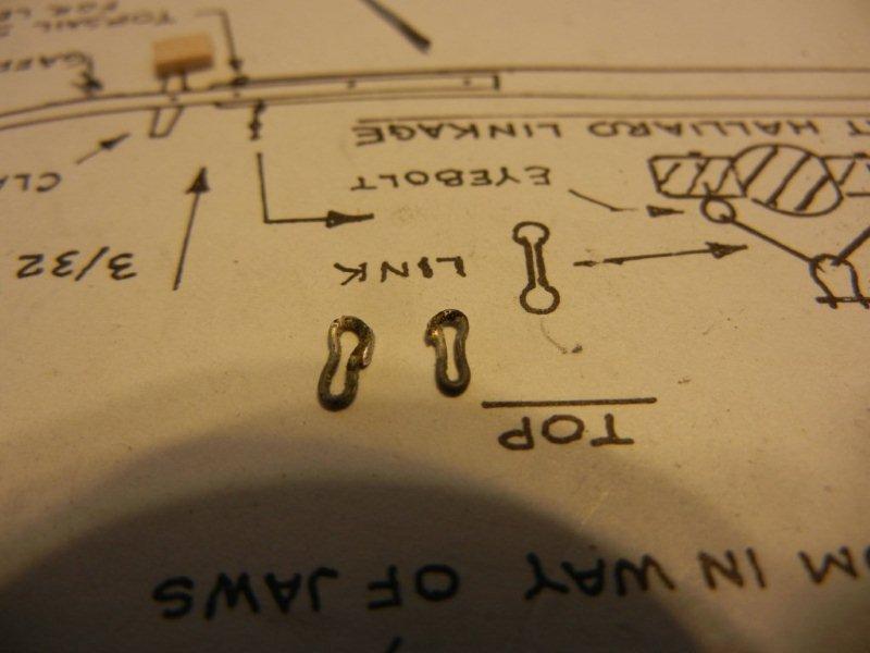
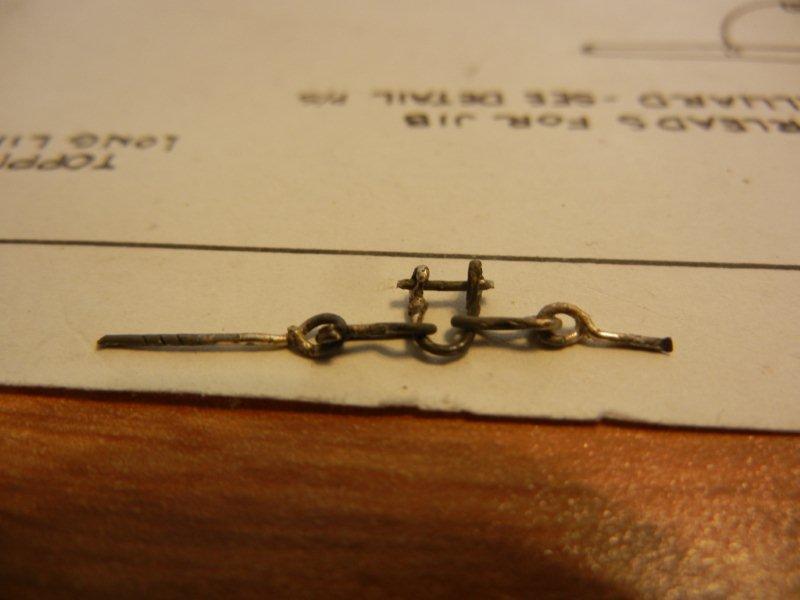
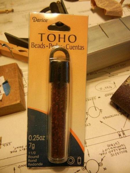
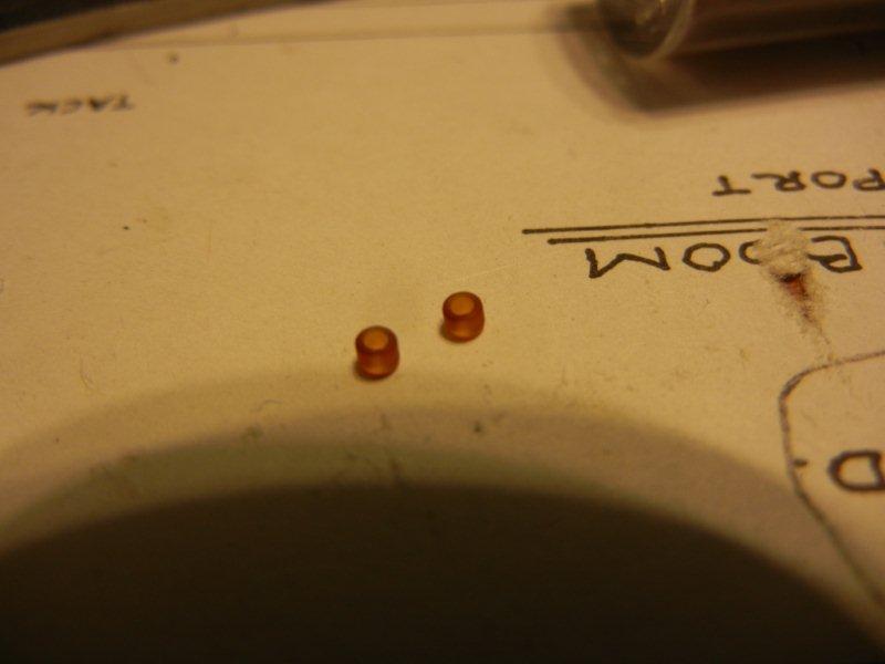
The next thing is the linkage for the block that will be rigged to the throat halliard. I built the first one by adding the parts in place on the gaff. It was a pain to get the shackle installed through the links, so for the second one I assembled all the parts off the gaff, then installed the completed assembly. First there are a couple of links to make. The complete assembly is eye-link-shackle-link-eye. After that the eyes are glued to the gaff jaws. And finally a shot with the block installed. The parrell beads are beads I picked up at Michaels Craft store. Bob

-
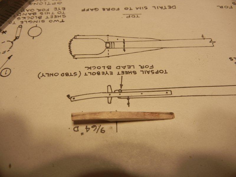
Next up is the gaff jaws. These parts are provided in the wood billets for the kit. The first thing needed is to shape the jaws as they have a curve at the end. Since the supplied wood is a bit thicker than what is required it is a matter of drawing the profile on the side and sanding away the excess. Profile lines drawn on the jaw. One jaw has been sanded - the other has its profile drawn. The pieces are laid out on the plan for positioning. Then they are glued and clamped Then holes are drilled for the "bolts" and the rough ends are filed off. A hole is drilled through for the clapper and the clapper is installed. The wire will be trimmed and filed to finish up the job. Bob

-
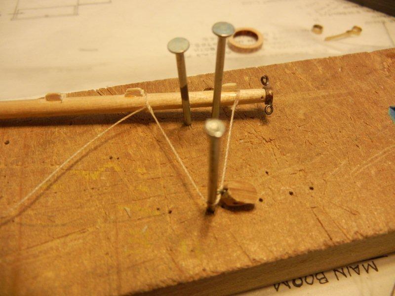
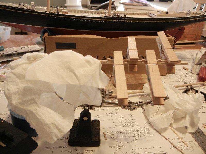
The last chock pair is a little different. And much simpler - one on each side. Here are the blanks, the first chock clamped in place, and the finished product. I used the following jig to set up the bridles and blocks for the peak halliard rigging. It was another chance to use Gil's splicing technique - that is starting to come together, although there is still a struggle to keep the splices from bunching up. The first bridle in the jig: And the final result: You can see a band at the end of the gaff. I still haven't tied the block to it for the topsail sheet The bridles were done in June 2012. Bob

-
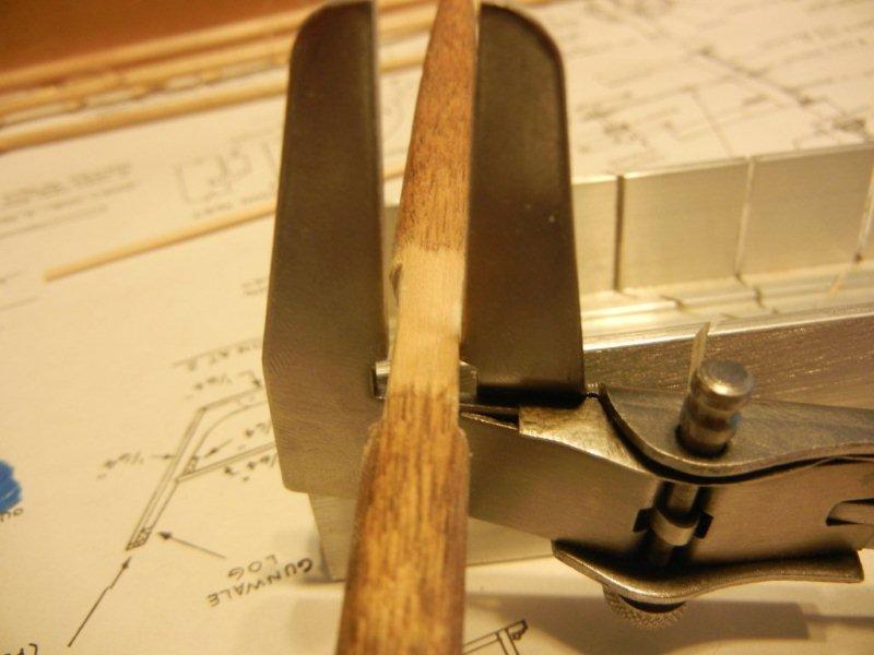
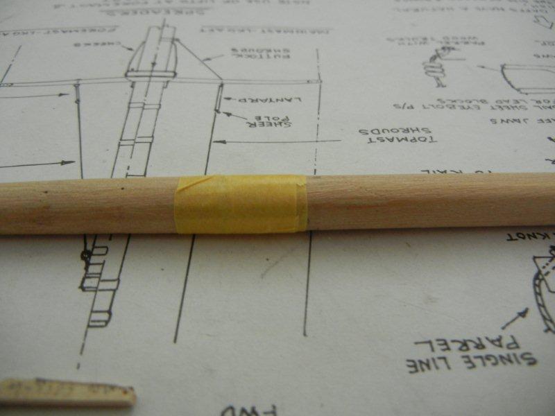
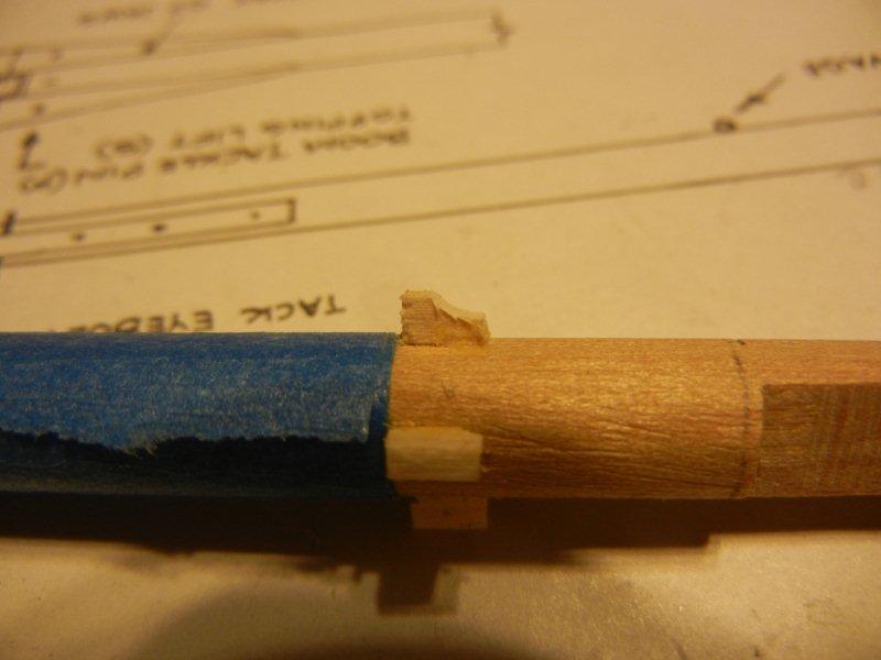
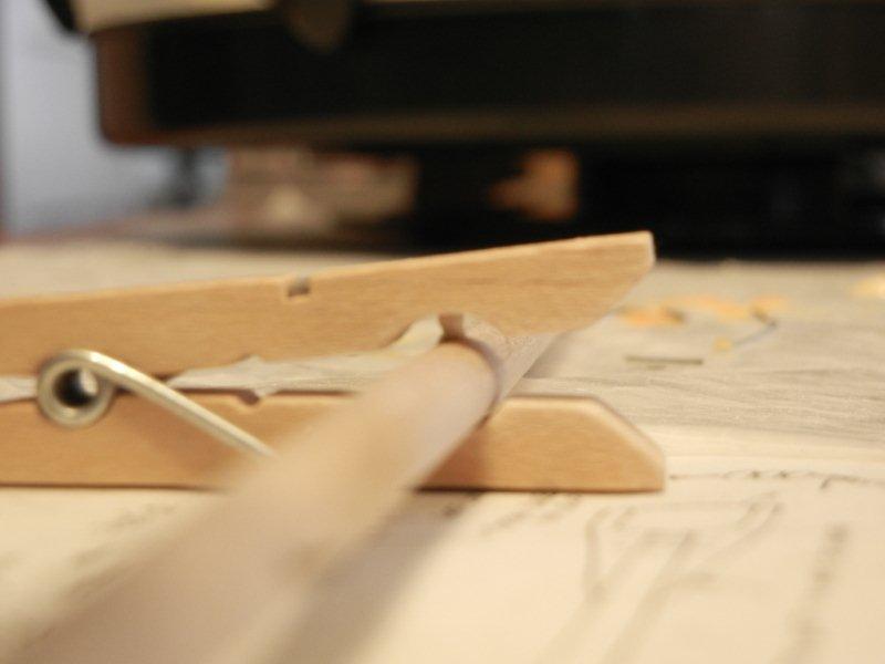
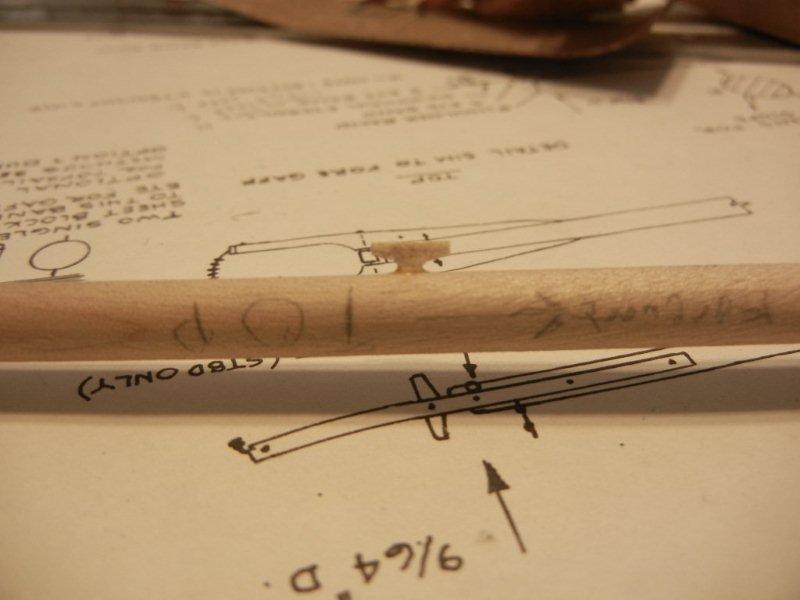
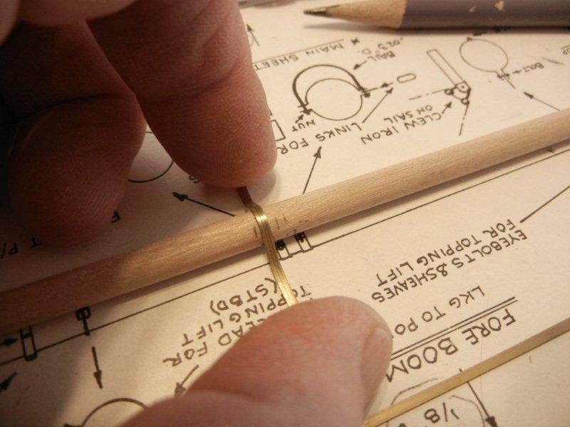
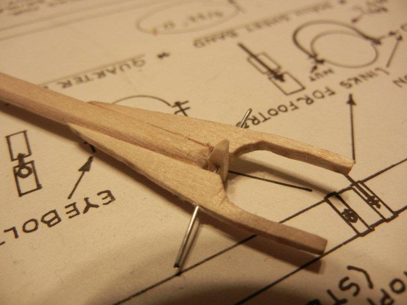
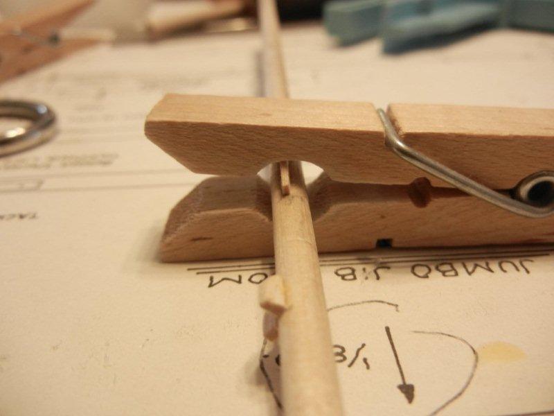
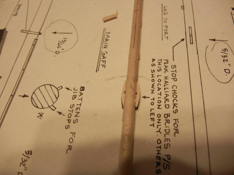
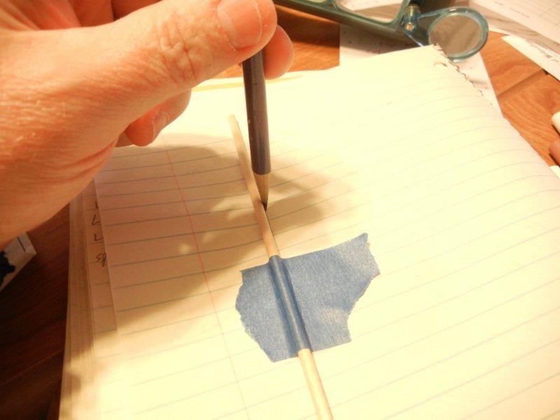
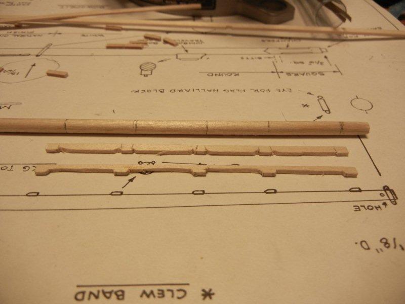
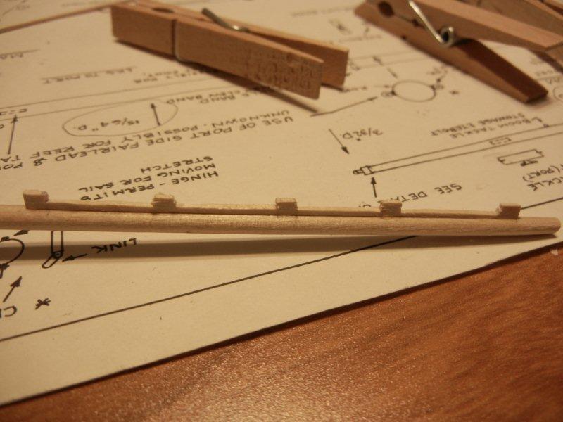
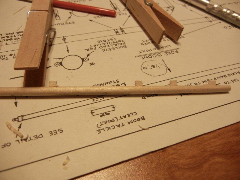
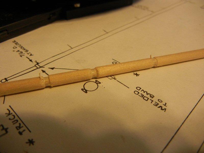
The next topic I'll cover is gaffs and booms. To give a feel for my somewhat erratic process, I started on these in November 2011 and was tying some blocks on a couple of days ago. In the meanwhile I have also spent time on masts and lots of bands. In short, doing an abbreviated log like this allows me to mask some of my scattered order of things. As I mentioned in an earlier post, all gaffs and booms (and the bowsprit) have one straight edge and the opposite side is tapered on both ends. It was important for me to keep track of that straight edge so bands, chocks, etc could be properly placed on the spar. I found a way to do this that was pretty simple and worked well for me. I taped the spar to a piece of paper and ran the edge of a pencil along one side. The resulting line marked the straight side quite well for me. Once the straight side was established, I could taper the opposite side based on the plans. I won't show this again as I covered it ina previous entry (and I didn't take a lot of repetitive photos of the process ). Working on the main gaff, there are a bunch of stop chocks that need to be installed to keep the bridles and blocks for the peak halliard from sliding down the gaff to the mast. I first tried to cut individual pieces and attach them to the gaff. I was unhappy with the result as the pieces were difficult to clamp and impossible for me to get lined up nicely. I thought about it and came up with the "chocks on a stick" idea. I marked a piece of stripwood with the location of the chocks and the carved some of the excess wood away. Here are the two sets in different states of carving. I them placed glue on the strip only where the chocks would remain, positioned the first strip and clamped it in palce with my favorite clamping tool. After gluing it looked like this: I then carved away the excess wood and was left with oversized chocks (you'll note that on is missing here, I was able to glue a single one in place more easily than a whole lot of them). I then followed the same process for the second set. Finally all the chocks were shaped using a file and a rasp and this was the result. Note: Russ suggested that I could have glued the chocks to the gaff with the individual pieces facing in and then just cut off the strip. That's why he is Master and I am just Grasshopper! Bob


-
What is your favorite hand tool(s)??
bhermann replied to Modeler12's topic in Modeling tools and Workshop Equipment
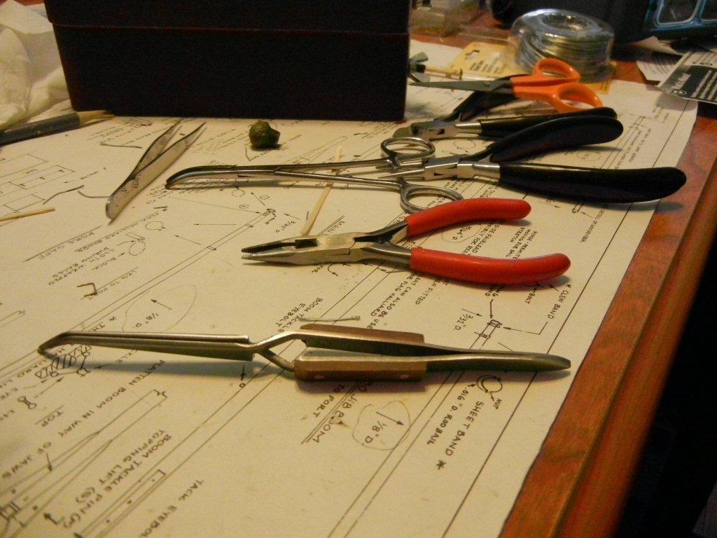
Favorite hand tool? There are just too many choices. Hemostats, and optivisor are a couple that others have listed and that are right up there with me. I recently picked up cross-locking tweezers and it falls in the 'how did I live without this' category. My reason for buying them was to hold bands for soldering. They apply enough pressure to hold the edges together without collapsing the band when it gets heated. I quickly started using them to replace conventional tweezers for holding small parts. The number of incidents where that small part flies out of the tweezers and into space has been reduced significantly, leaving me more time to model and less time crawling around the floor looking for deadeyes! Bob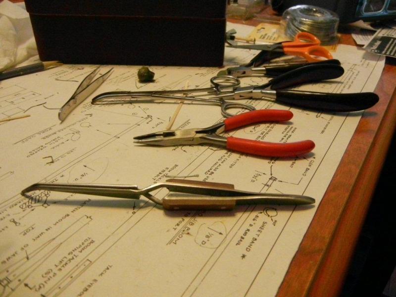
-
cb - thanks for taking the time to put some detail into this. As you say, getting the base correct will go a long way toward producing a good finished product. Emma is on my list of potential future build (if I ever feel up to a POF challenge. I will be following along with great interest. Bob
-
chouser - the old log will not be back in it's original form... in case you haven't heard, check out this link for details: http://modelshipworld.com/index.php?/topic/187-all-the-content-on-the-site-was-lost-we-need-to-start-from-scratch/ I did not keep a copy of the log and am trying to recreate as much of the build detail as I can, trying to focus on what I recall as being milestone moments or technical items of interest. If you have specific questions about something feel free to ask and I'll do my best to provide my thoughts on them. Are you building a Bluenose too? If so, I highly recommend starting a log of your own. It's a great way to get feedback and to motivate yourself to keep going. The gang here at MSW is very helpful and encouraging. Bob
-
Hi, Floyd. I will be watching this build we great interest. ALs Harvey is one of the dismal failures from my sordid past. Picked up as an impulse buy at Mystic Seaport, I managed to get the keel and bulkheads installed and the false deck attached. I them proceeded to first plank the hull with the material meant for the deck planking. I didn't know anything about wood at the time and the kit instructions read something like "the wood for first planking is so flexible you can tie it knots" so I grabbed the most flexible stuff in the box. I will watch your build and live vicariously through your reporting. Have fun, and use the ramin wood in the correct place Bob
-
Glad to have you stop by Alfons, I'll have to drop over and see what you are up to. There will be more updates concerning masts and other spars in the next day or two. Bob
-
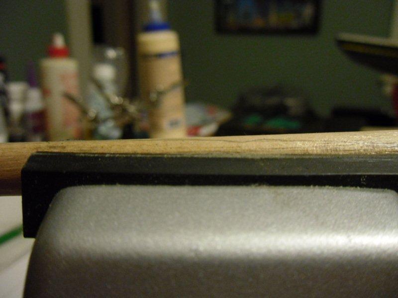
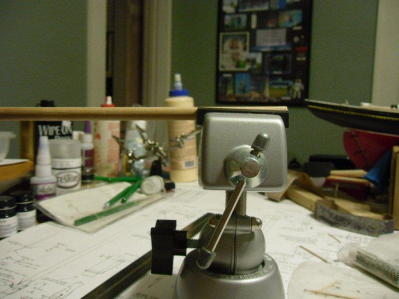
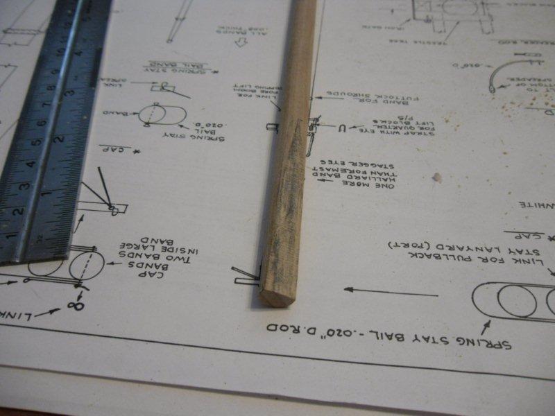
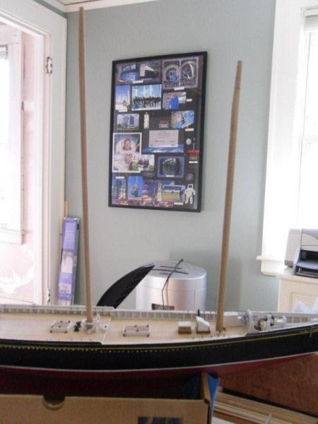
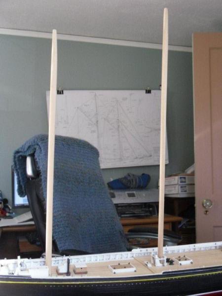
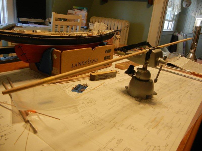
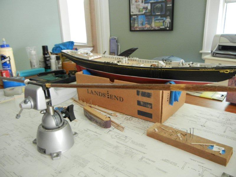
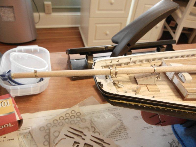
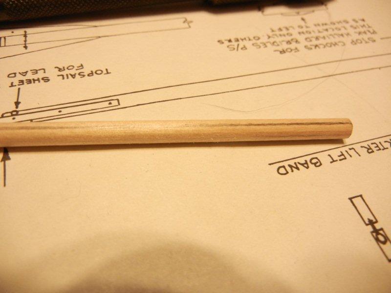
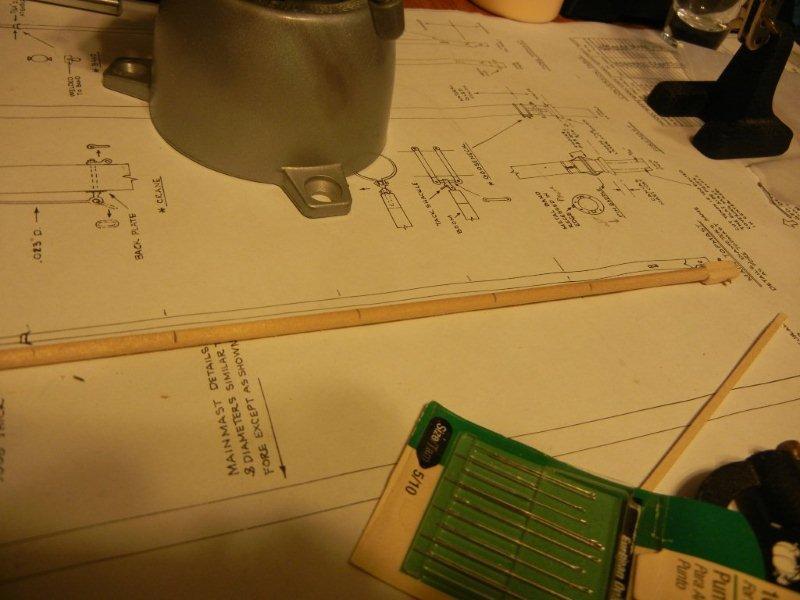
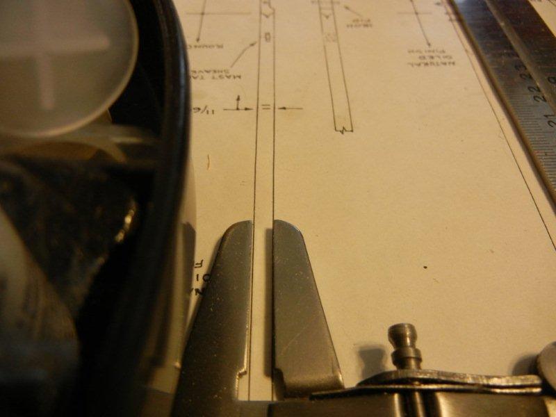
For the symmetrical tapers I use a similar sanding technique (because I didn't trust myself to keep from removing too much material if I tried the "chuck the dowel in the drill" method I have read about. First I lay the spar on the plan and mark corresponding points on the mast and the plan. The I use the caliper to measure the width of the mast at one of the points and to transfer the width mechanically to the dowel. This spar has had several locations marked and transferred. Then into the vice for removing excess material as I did for the asymmetrical tapers. I do this in 4 different planes to form a square section which is then sanded round to finish up. And here is the result. The top of the mast will be shaped later to form the ball that belongs there. After shaping, staining and painting (and a bunch of other work) this is what they look like. Bob


-
JP - I'm glad to be of service - it is one of my "big 3" reasons for doing a log. Thanks for stopping by, Elia. I find that I am rediscovering things as I look back through the old photos. Dave - yeah, those sails are scaring the crap out of me. I have two different piles of cloth in the corner of the room waiting their turn... it's coming soon. I look forward to seeing your success story... And now a word on tapering spars. Bluenose has two different types of tapering going on... the traditional symmetrical, taper to a point type that is done on the topmasts, and an asymmetric, one side stays straight while the other narrows that is used on the lower masts, the gaffs, booms, and bowsprit. I am going to start with the second type. I am showing the mainmast, but I used the same process for all of these. First I lay the dowel on the plan and mark the final width at the end of the dowel and the spot on the dowel where the taper starts. Then I put the dowel into the vice with the section to be removed rising above the jaws. Once that is positioned, I sand everything off that is above the jaws until I am left with a flat side that gets wider at the end of the dowel. After this is done I carefully sand the flattened section until it is round all the way up the dowel again, taking care not to remove any material from the side that has no taper. The finished product for the main and foremasts looks like this: The masts just have a taper at one end. The other spars are tapered at both end (so they have a bowed profile when viewed from the side). This is done by applying the same technique on both ends, one after the other. Bob