


bhermann
-
Posts
545 -
Joined
-
Last visited
Reputation Activity
-

 bhermann got a reaction from tasmanian in Bluenose by bhermann - Model Shipways 2130 - 1:64
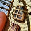
My most recent work (which means I've been working on the main gaff for over a year ) was to install a block on the underside of the gaff jaw. The topsail sheet will be run through this block en route to a belaying pin on the starboard side.
This pretty much finished up the main gaff. There is one more block for the topsail sheet at the upper end of the gaff but the only thing left to do there is to mouse the hook.
The fore gaff has much the same hardware on it except the blocks for the peak halliard are attached to bands rather than bridles, and there are two sets of blocks for the topsail sheet as it needs to be able to be set on either side of the main topmast stay.
Bob
-
.thumb.jpeg.fc5d633a7b34428fcf19419a73d56d55.jpeg) bhermann got a reaction from EricWilliamMarshall in Bluenose by bhermann - Model Shipways 2130 - 1:64
bhermann got a reaction from EricWilliamMarshall in Bluenose by bhermann - Model Shipways 2130 - 1:64
The next thing is the linkage for the block that will be rigged to the throat halliard. I built the first one by adding the parts in place on the gaff. It was a pain to get the shackle installed through the links, so for the second one I assembled all the parts off the gaff, then installed the completed assembly.
First there are a couple of links to make.
The complete assembly is eye-link-shackle-link-eye.
After that the eyes are glued to the gaff jaws.
And finally a shot with the block installed.
The parrell beads are beads I picked up at Michaels Craft store.
Bob
-
bhermann got a reaction from EricWilliamMarshall in Bluenose by bhermann - Model Shipways 2130 - 1:64
I added some blocks and other hardware to the trestle trees.
First the foremast. Fore side
Aft side
main mast aft side
A couple of shots of putting tension on the line while mousing a hook.
Bob
-
 bhermann got a reaction from Elia in Bluenose by bhermann - Model Shipways 2130 - 1:64
This pretty much catches me up to date. if there is anything I missed from the old log that you would like to see, please let me know. Here are some shots of the mast detail. If you look closely you will see holes drilled for "mast sheaves" in the topmasts. I don't know what they were used for - my best guess is that they had something to do with stepping and unstepping the topmasts.
Main mast top
Fore mast top
Main topmast detail
Fore topmast detail
Thanks for all the support and encouragement over the past few years - now to move forward!
Bob
-
bhermann got a reaction from tasmanian in Bluenose by bhermann - Model Shipways 2130 - 1:64
In case I haven't shown this before (in this incarnation of the log) here is the setup I use for mousing hooks. The secret for me is keeping the connection being moused under tension so I can have both hands free to do the work. In this case that means putting a thread through the block being moused and clamping the end in a hemostat that is draped over the third hand so gravity will keep the line tight. The spar is clamped into the Panavise. Before setting up I tie the mousing line on the hook. The knot winds up hidden inside the wrapping.
The business end of the previous photo
I then dab a little CA onto the hook, give it a couple of wraps and hold it in place for a minute or so.
Then I take the working end of the thread and put it back through the mouse with a needle and dab with CA again.
After trimming the excess thread, this is the result. The hook will slide around the eyebolt but it doesn't come off.
There - the block for the main topsail sheet is now attached securely.
Bob
-
 bhermann got a reaction from GrandpaPhil in Bluenose by bhermann - Model Shipways 2130 - 1:64
Jan-Willem
Here are the photos you requested. Hope it helps. That solid block you see runs all the way to the stem where it wraps around the bowsprit.
I think the stanchion count is accurate. I suspect that not every frame is continued above the deck so the number of stanchions is less than the number of frames.
Enjoy, and let me know if I can share anything else with you.
Bob
-
 bhermann got a reaction from Leo-zd in Bluenose by bhermann - Model Shipways 2130 - 1:64
Jan-Willem
Here are the photos you requested. Hope it helps. That solid block you see runs all the way to the stem where it wraps around the bowsprit.
I think the stanchion count is accurate. I suspect that not every frame is continued above the deck so the number of stanchions is less than the number of frames.
Enjoy, and let me know if I can share anything else with you.
Bob
-
 bhermann got a reaction from hexnut in Bluenose by bhermann - Model Shipways 2130 - 1:64
Jan-Willem
Here are the photos you requested. Hope it helps. That solid block you see runs all the way to the stem where it wraps around the bowsprit.
I think the stanchion count is accurate. I suspect that not every frame is continued above the deck so the number of stanchions is less than the number of frames.
Enjoy, and let me know if I can share anything else with you.
Bob
-
bhermann reacted to JerseyCity Frankie in When to fit sails?
I can never resist putting in my two cents on the issue of weather or not to include sails on a sailing ship model. I always try to advocate for including the sails since I view them as a defining aspect of a sailing vessel. The argument against sails is most often framed from the perspective that "they block the view of details on the model" and that they "are difficult". I will certainly agree that they are difficult! But I don't think that is an excuse to leave them off the model. The idea that they block the view of other aspects of the ship is true only in the sense that actual sails block the view of actual aspects of an actual ship. Thats how actual ships appear. Incidentally there are other things that are difficult to manage on ship models which ALSO block the view of deck details and are time consuming and difficult to make and install: Cannons! But you NEVER see people omit the cannons.
-
bhermann reacted to LMDAVE in Endeavour by LMDAVE - FINISHED - Amati - 1:80 - J-Class Yacht
Starting out on some rigging. I rigged the shroud lines first. The problem I was having was color, should I use black or tan? Standing rigging is usually black, but I see a lot of the standing rigging on endeavour tan. I started black on the shrouds, then made the switch when I did the forward stay to tan. I will continue with tan. I hope the shrouds dont standout out as an outcast in the end being the on black rigging. I like it so far. Here are a few pics of the rigging starting.
-
bhermann reacted to EdT in Young America 1853 by EdT - FINISHED - extreme clipper
Young America - extreme clipper 1853
Part 80 –Middle Deck Hanging Knee
I usually limit the content of these posts to progress reporting. Except for some general comments I don’t usually do step-by-step demos in these. This post is hardly a tutorial, but I am spending so much time on deck beam knees that I decided to focus on making one of those. There are roughly 250 hanging knees and an equal number of lodging knees in the model, so it is hard to ignore this process. I try to follow Remco’s advice on these to treat every part as a separate model, but its not always easy. Four or five a day are my limit.
We’re getting down to the wire on the middle deck framing. As the beams get closer, the fitting of the knees requires more contortions as evidenced in the first picture.
The subject knee is being fitted under a half beam, so the beams fore and aft are already in place. A few of these knees inevitably end up in the hold during this process. After the knee is cut from one of several generic patterns, it is fitted by trial and error as shown – in and out maybe 6 times. Most of the trimming is done with the disk sander.
Once it is fitted , the knee is removed to the vise for bolting and final finishing. In the next picture the bolt holes are being center marked.
There were 15 to 18 1” iron bolts securing each knee. I am aiming for about half that number – sometimes less - in the model. In the next picture the bolt holes are being drilled.
This is a number 73 (.021”) drill to slip fit a bolt of 20 lb test black monofilament. This is equal to a 1 ½” head at 1:72 – about the size of a riveted 1” bolt head. In the next picture the monofilament bolt is being glued in with CA glue.
It will be sliced off flush with the razor blade. The excess glue and any protruding monofilament is then filed off with a coarse rounded file.
This surface is then sanded with 220 and 320 grit paper on dowels. In the next picture the corners are being rounded off.
Finally, the finished knee. Note the notch for the deck clamp.
The last picture shows the glued-in knee in the center of the picture on the half beam.
In a later step, the knee will be further secured with a copper wire bolt inserted and epoxied through the beam and well into the knee from above. Several other simulated bolts will then be installed over the knee in the beam. Another copper wire bolt will replace the pin in the picture.
At this stage only one knee is left to do – on the half beam missing from the picture. Then on to the lodging knees and ledges.
Ed
-
bhermann got a reaction from Elia in Bluenose by bhermann - Model Shipways 2130 - 1:64
LOL - if you do order the tap and die set make sure to get both RH and LH threads - so you can make those working turnbuckles!
I am not at a complete standstill - in fact my mind is going 200 mph, even though the build itself is crawling. I did manage to finish making and cutting out the templates for the sail set. Don't know if I'll use the fisherman sail, but I have it if needed. I may add a third reef band to the mainsail - it seems too large not to have the option.
The sails laid out:
and where they are going to:
A closer look at the destination. I see the mast hoops are too thick, but I have to remember I have a few extras on the mast in case of breakage.
Still working out the details of sail construction in my mind. I am pretty clear on drawing the hem lines, not stitching them. I am debating on whether to fold the hems over and glue them, or to get an iron-on edge and trim that to the actual sail size. Anyway, here are a couple of shots of where I am at the moment.
Bob
-
bhermann reacted to trippwj in Emma C Berry by trippwj - Model Shipways - Scale 1:32
Well, after having the summer to relax, the Emma C. Berry has come back to the build table. She was getting a mite snippy sitting on the shelf in my business office.
Prior to resuming work, took a ride to Bangor yesterday to pick up a Harbor Freight work bench - the Admiral and son the elder helped get it set up. After a bit of organizing this morning, have removed the temporary battens that I glued on (not the brightest thing I have ever done) and replaced with pins. Also have beveled and installed the transom.
Next step is to fine tune the tops of the frames (a couple are just a smidge long or short - fortunately they get covered by the covering board and are hidden) then prepare and install the clamps. From there, into the building of the interior - that should take quite some time!
Profile view
View from the stern
A quick tour of the reorganized shop.
Many thanks!
-
bhermann reacted to EdT in Young America 1853 by EdT - FINISHED - extreme clipper
Young America - extreme clipper 1853
Part 79 –Middle Deck Framing continued
The middle deck framing continues. The first picture shows the opening for the large water tank being framed.
The header between beams 16 and 20 has been installed and the half beam at 18 fitted temporarily. The large 6000 gal fresh water tank will fill most of the space in this opening from its base in the hold to just under the main deck beams.
In the next picture the hanging knee and the pillar under the half beam are in place and the half beam is ready to be installed.
The smaller 2000-gallon water tank will come up to just below this deck . Its top will fit in the currently unframed opening between beams 16 and fourteen in the upper right of this picture.
In the next picture the pillar under the starboard half beam is being fitted for size.
The next picture shows this area looking down and aft. The paired pillars on either side of the tank opening can be seen in this picture.
The next picture shows the extent of framing aft of midship completed to date. One full beam and two pairs of half beams remain to be fitted – then the lodging knees and ledges.
Some of the lodging knees have been fitted at the aft end of the deck. The last picture shows the stern view opening. As mentioned earlier, this one shows only the space between the middle and lower decks.
The exposed ends of the frames have been fairly well squared off in this picture, but there is still finish sanding, etc to be done. The outsides of the frames have been faired, but final sanding and finishing cannot be done until many more simulated bolts are installed. Those in the picture are bolts for the deck clamps and for the heavy internal bilge ceiling. Bolts for deck knees have not been installed yet.
Ed
-
-
bhermann reacted to LMDAVE in Endeavour by LMDAVE - FINISHED - Amati - 1:80 - J-Class Yacht
I haven't posted any updates in a while. Mainly just working on more deck stuff. It's getting pretty cluttered, and still have all the outer eyebolts to add. This pic mainly shows all of the wooden cleets that are scattered about the deck. I placed them as accurately as I could to the plans, and angled them as the plan shows. The cleets came as cast metal and were suggested to be painted brown to look wooden. I see some leave them as chrome, but I took the wood route. I like to try to my paint items look real like real wood, but couldn't really do much with these little suckers. So, they are just pretty much a solid flat brown.
-
bhermann reacted to dgbot in USS Maine by dgbot - HMV - 1/250 - CARD
Once everything was added to the side panels they were glued into place. The first thing I did was to tack the bow sections in place so I could make sure everything was even on both sides. And glued the sides to the hull. I then noticed that one side was about a 1/16 to short. So I cut a section and added a strip to make it fit. A little pressure and the seam is hardly noticable. I will proceed to hide it as I proceed with the model.
David B
-
bhermann reacted to dgbot in USS Maine by dgbot - HMV - 1/250 - CARD
I have been able to get some more into the Maine and was able to finish off the two cabins.
And here is where I found that rubbing alcohol can be your best friend.
While fitting the roof of the forward cabin I noticed that the walls were not fully aligned. By using a brush and a drop of rubbing alcohol I was able to reposition everything for a better fit. Plus the alcohol evaporated quickly and did not stain or damage the material. Once the roof was placed to my satisfaction I glued it down using a weight to hold it until the glue dried. Then a little touch up with a brush and it is about as good as I can make it.
.
David B
-
bhermann reacted to Jim Lad in Francis Pritt by Jim Lad - FINISHED - Scale 1:48 - Australian Mission Ship
Another very small update.
Last time I was in the museum I temporarily abandoned the deck clamps in favour of starting to fit the bilge stringers, as one of the other model makers came in and wanted to photograph the process of inserting treenails for an article he was writing and the bilge was easier for his camera focus.
What with photos, yarning about model making and an extended lunch in the museum café, I didn't get much done!
John
-
bhermann reacted to Omega1234 in Ingomar by Omega1234 - FINISHED - 1/278 - Hereshoff designed schooner
Hi all
Here are two videos of Ingomar's hull. I hope they work (this is the first time I've ever uploaded something to You Tube!) Pls excuse the amatuerish video quality....hopefully I'll get better at it.
Hope you enjoy.
All the best!
-
bhermann reacted to EdT in Young America 1853 by EdT - FINISHED - extreme clipper
Young America - extreme clipper 1853
Part 78 –Middle Deck Framing continued
It has been almost another two weeks since the last post. Again, the work is pretty repetitive – a carbon copy of the lower deck – but with fancier pillars. Work continues, however. At the bow, as seen in the first picture, the installation of lodging knees has begun.
This has provided something of a break in the hanging knee/beam work going on aft. In the next picture lodging knee installation has been followed by the ledges and also the bolts associated with each beam.
Meanwhile, in the next picture, 240 feet aft, the deck hook at the stern has been fitted, followed by the first few beams.
The deck hook was made in two pieces to save Swiss pear trees. That center seam will be covered by central deck planks as was done on the lower deck.
As middle deck beams were installed, the aft view ports could be cut, as shown in the next picture.
There is only one level in view in these aft openings because the rising line is quite high this far back, so there is nothing much to see below the lower deck. The last picture shows the current state of the middle deck beam work aft.
The work goes fast when I stay with it, but this time of the year there is much else to do.
Ed
-
bhermann reacted to rcmdrvr in Willie L Bennett by rcmdrvr - FINISHED - Model Shipways - SMALL
I was able to spend almost a whole day in the workshop and got a lot done. First I completed planking the bottom of the boat and begin work on the interior. The plans provide the information to detail the entire inside of the hull. However, all of this would then be covered. I have looked over other builds of the Willie and I have decided that I will not detail the interior. I will concentrate on those portions of the model that will be viewed.
My next step will be making the structure that will support the deck.
-
bhermann reacted to Laxet in US Brig Niagara by Laxet - FINISHED - Model Shipways
Hey, look! I've got a base board now! That's almost like launching a ship (to me). A milestone of sorts. I'm a proud papa.
-
bhermann reacted to rafine in Frigate Essex by Rafine - FINISHED - Model Shipways - Kitbashed
I'm just back from a week long golf trip with my wife and three other couples, and after playing 6 times in 7 days, I was ready for a rest from golf and eager to get back to modeling. This combination resulted in a burst of activity.
I returned to work on the forecastle. First I realized that I had left off the knees on the belfry/barricade, so made and added them. Then I made and added the splash guards at the bow. These were cut from boxwood and bent to shape. Next, I made and mounted the 8 required timber heads. Theses were done from boxwood strip in the usual fashion of shaping each of them fully before cutting it from the strip. They were then painted and pinned and glued in place.
The last and most intricate work was making up the catheads. These were made from boxwood. notches were cut with a chisel to fit over the rail and the remainder of the shaping done with files. I did simulated sheaves, as I have done throughout this build. Next, I made and mounted the cleats and thumb cleats. Lastly, I added the necessary eyebolts. The catheads were then mounted in place.
I'm now moving on to the rough tree rail, which will be the last of the forecastle work.
Bob
-
 bhermann got a reaction from trippwj in Emma C Berry by trippwj - Model Shipways - Scale 1:32
Wayne -
it may be time for a mutiny - I don't know if it's fair to give us this tease and then not start on the build. I am looking forward to when you can get this build under way.
Bob