EdT
-
Posts
2,214 -
Joined
-
Last visited
Content Type
Profiles
Forums
Gallery
Events
Everything posted by EdT
-
I would say the same to you, Giampiero.
-
Good work on the thickness sander! One of the most important and useful tools for the ship model builder. Ed ...and spectacular work on the corvette.
-
Thank you, Ian, and thanks for the tip. Making a b&w negative is easy enough to do in the image editing software. Ed
- 3,618 replies
-
- 6
-

-
- young america
- clipper
- (and 1 more)
-
Thank you, everyone for the comments and likes. I am running out of ways to express thanks. Tom, I use a tripod and the 10 second timer on the camera. This allows me to pose the picture, focus the camera and click the shutter, then return to work, stopping movement when the beeps accelerate before the shutter releases. The tripod can be an annoyance since it is constantly present - and I have knocked it over once - at the cost of a new lens. To support the books and the blog, I take between 150 and 300 photos per month. I have taken 120 so far this month. I also use them to critique the work and look for problems that the eye doesn't always see. It is my constant companion - that and its battery charger. Ed
- 3,618 replies
-
- 16
-
-
- young america
- clipper
- (and 1 more)
-
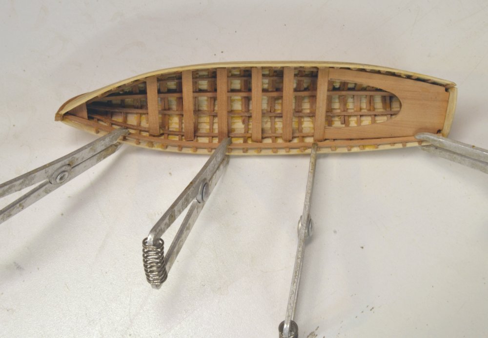
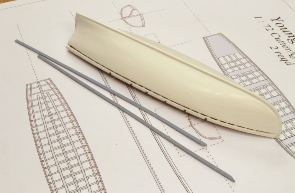
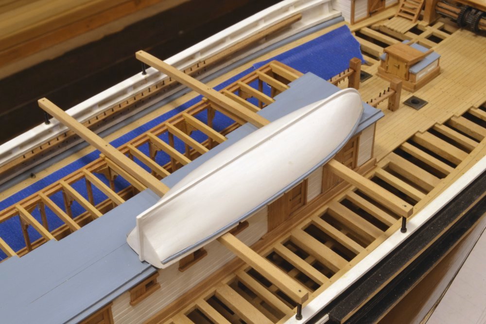
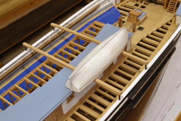
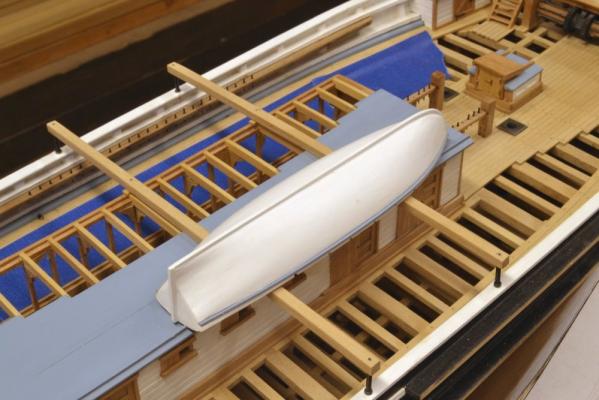
Young America - extreme clipper 1853 Part 148 – Ship’s Boats 4 The last picture in Part 147 showed the top plank being glued on to longboat 1 with the channel wale inserted to provide a space for its later installation. In the first picture the wale has been removed. The frames may now be cut down to the top of the side and the boat removed from the plug. The next picture shows the keelson being glued to the tops of the frame floors. The longboats were pretty heavily constructed. They were working boats that carried supplies or cargo and sometimes even an anchor. Ceiling stringers at the turn of the bilge can be seen in this picture as well as clamps to support the seats. In the next picture a clamp at the wale height is being glued in after installation of the seats. I tried not to fuss too much with this interior work because the boats will be fixed to the skid beams inverted roughly in the position shown in the next picture. The 25’ cutters were secured just outside of the longboats. I expect to tie down spare spars and lower studding sail booms between the longboats. In this picture the outer planking of longboat 1 has been given a coat of white shellac as a sealer and that has been sanded smooth. There will be a second shellac seal coat and sanding before the final white gloss acrylic finish. The channel wales will be the same blue as the cabin roof. All the pin rails visible in this picture have been fitted with their pins. The blue masking tape was applied to stop the dropping of belaying pins into the hold. In the next picture both the boat and the two wales have been painted and are ready for final assembly. The last picture shows the boat placed on the skid beams. Rudder hinges are still required. Boats were also required to have the ship’s name lettered on the transom and bow. This may be more than I can manage, but we’ll see. Before mounting the boats I need to check for rigging clearance between the outer boats and the pin rail. I believe all the lines that belay in the way of the boats go through shroud fairleads so there should be no problem, but it is worth a check. It may be best to avoid securing these boats until rigging has been belayed below the boats. Ed


- 3,618 replies
-
- 46
-
-
- young america
- clipper
- (and 1 more)
-
Roger and Bob, thanks for the additional information on the book. I will pursue it further. We are indeed indebted to Google for their work in scanning and putting online many historical technical works of interest to model builders. As I write this I am wading through several on 19th century rigging. Bob, it is true that on some frames the at both ends of the square framed sections where there is maximum frame bevel. In fact,you should find that the point where the bolts approach either the inner or outer edges of the frames is the point where the cant frames begin, allowing bolts to be driven "normal" - i.e. at right angles to the face of the frame - while not penetrating the outer or inner edges. Although bolts in these last square half frames are very close to one edge, due to the bevel, they go through the central section of the piece and usually emerge at the opposite (inner or outer) edge on the mating frame. If this sounds confusing, it is. The alternatives are to either start the cant frames much closer to midship or to drive bolts at an angle. The first would weaken the hull significantly. The latter choice is less clear. Some sources indicate that bolts were always - or at least preferred to be - driven normal. However, I found some pictorial evidence (and posted the picture earlier ) of bolt holes being driven at an angle. This was taken in the early 20th century and a pneumatic drill was being used. I kept all the bolts normal because I concluded this was the practice at the time (1850's). Also, and very important to the model, normal holes were essential in the pin-indexed process I adopted for fabricating frames. Keep in mind that these bolts were mainly used to keep the frames connected for erection. The real strength that held these together came later when the inboard and outboard planking was secured by either structural bolts and or treenails. At this point I believe the iron bolts through the frames became superfluous. On the frame patterns the holes were placed very carefully on these beveled sections and I found in building the model that none broke through the edges, but as you say, at the ends of the square framed areas, they get very close. I will add the typo you noted on frame Ra to the list. Ed
-
ancre La Salamandre by tadheus - 1:24
EdT replied to tadheus's topic in - Build logs for subjects built 1751 - 1800
Lovely work, Paul. Ed -
Pandora by marsalv - FINISHED - 1:52
EdT replied to marsalv's topic in - Build logs for subjects built 1751 - 1800
Beautiful clean work. Bravo. Ed -
ancre le rochefort by cabrapente
EdT replied to cabrapente's topic in - Build logs for subjects built 1751 - 1800
A good start on what I am sure will be another beautiful model. Can you tell us the scale please, and also the type of wood? Gracias, Ed -
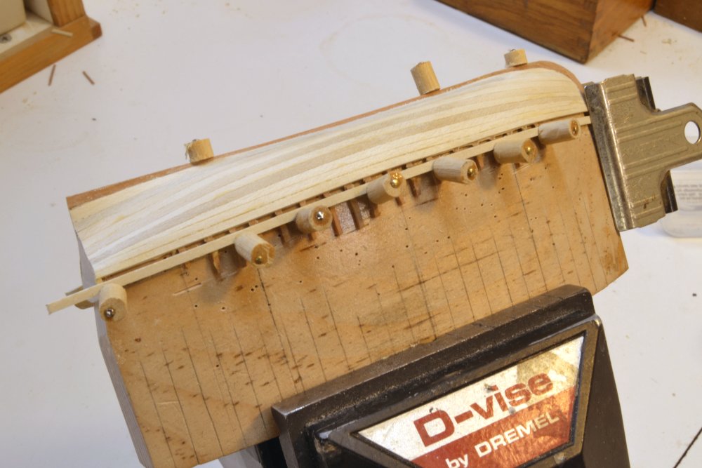
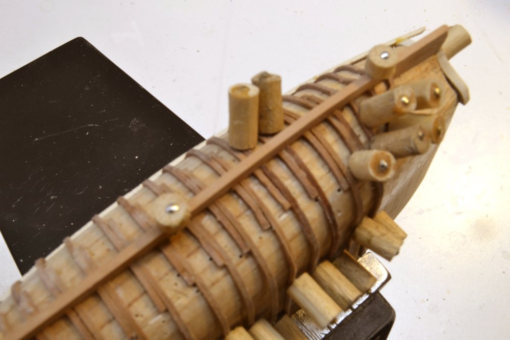
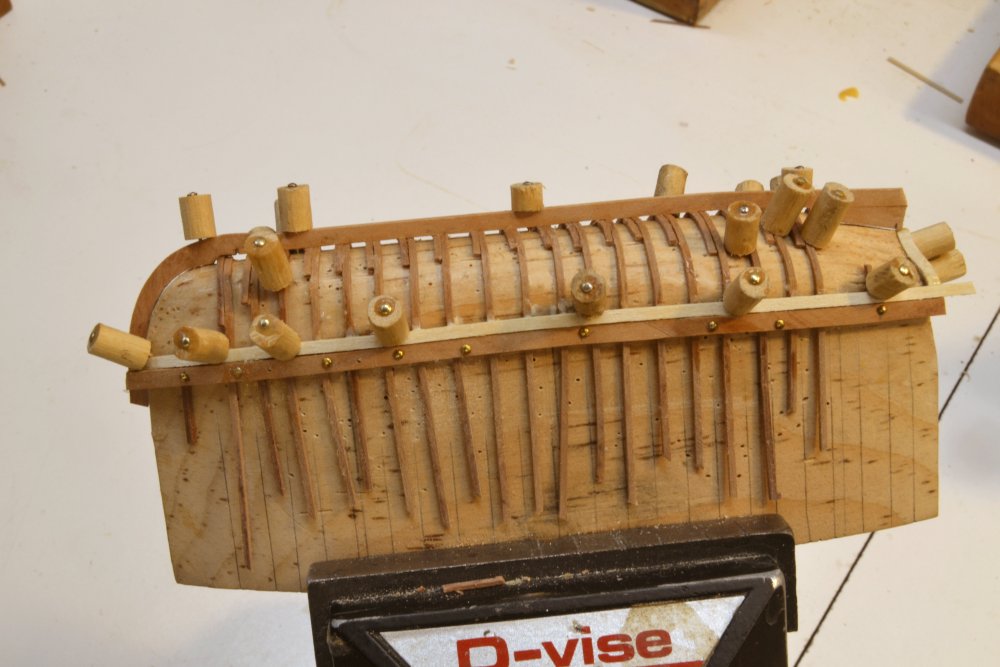
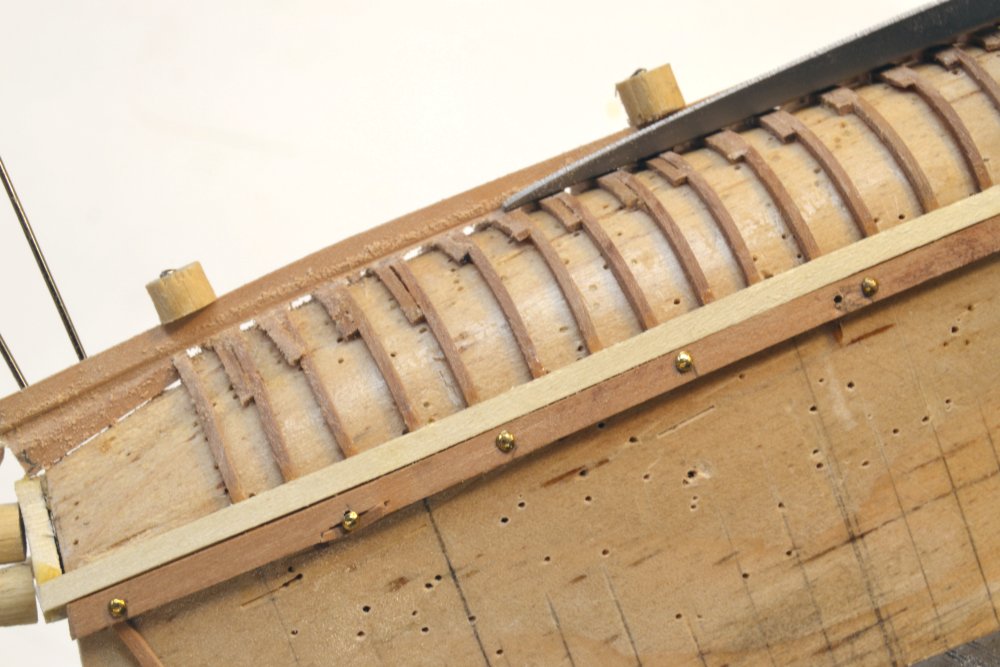
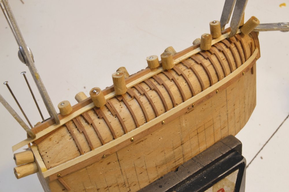
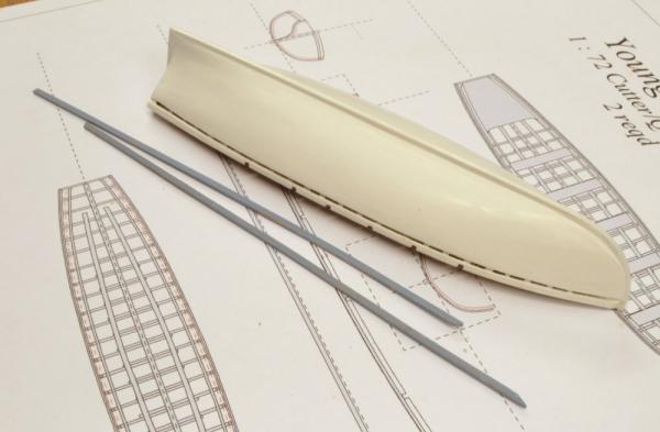
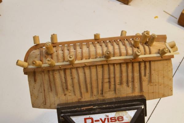
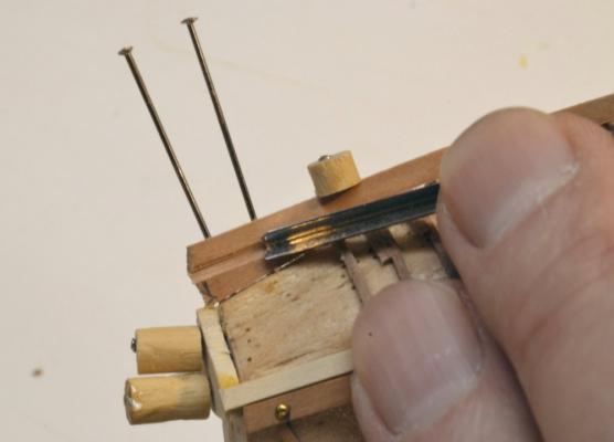
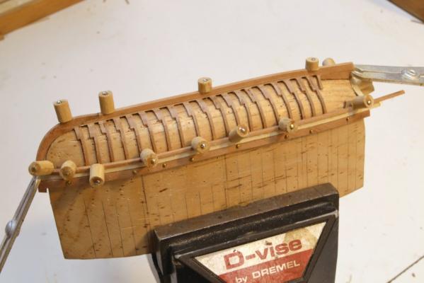
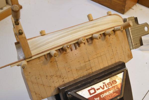
Young America - extreme clipper 1853 Part 147 – Ship’s Boats 3 In the last part the frames were installed on the port side of the plug. The first picture shows the starboard side framing in progress. The frame strips were left to soak in water overnight, making them very flexible. They were then brushed with glue where they would mate with the opposite frame and the keel and then pushed under the keel. Each frame was then pinned down at both ends and sometimes in other places as shown in the picture. The next picture shows the topside plank on the starboard side being installed against the nailed guide strip. I intend to leave this side unplanked to show the framing, so only the wale below the top plank will be installed on this side. On the other (port) side, the nailed guide strip and this top plank were also installed. The next picture shows the keel rabbet being pared out on the port side to prepare for the garboard strake. The rabbet at the deadwood and on the stem were pared out first with a V-gouge as shown in the picture. These areas were then cleaned up and the remainder of the keel rabbet formed using the barette file shown in the next picture. The garboard strake was then installed as shown below. Back on the starboard side the channel wale was installed just below the top plank while glue was drying on the port side planking. I mentioned earlier that all the work shown above was done on longboat two, the second to be made. At the same time, work was proceeding on the first boat. The next picture shows that boat fully planked below the channel wale on both sides. The wale has been temporarily inserted so the top plank can be glued on. As on the ship’s hull, boats will be painted, and the channel wales shown in a contrasting color, so they will be glued in after painting of both the hull and the wale to ensure a clean line. In the next part I will pick up on work to finish longboat 1. Ed


- 3,618 replies
-
- 45
-
-
- young america
- clipper
- (and 1 more)
-
Lovely work, Nils....and I love the design of the bow with the breakwaters. Ed
- 2,625 replies
-
- 4
-
-
- kaiser wilhelm der grosse
- passenger steamer
- (and 1 more)
-
Sorry, Richard, my last post seems to have crossed yours in transmission. Volume I covers the content shown in the first 118 parts of the build log - just before starting on the deck cabins. This was the status of the model in May 2015 - after about 18 months work. Ed
- 3,618 replies
-
- 4
-
-
- young america
- clipper
- (and 1 more)
-
Thanks, Allan and George - and all those who posted likes. I used the pear primarily for the color contrast - although this will be hard to see with the boats inverted on the skid beams. Actually, I am considering leaving the port side of longboat 2 in frame since it will be over the unplanked part of the ship - actually the starboard side since they are upside down. Thanks for the tip, Allan, and by the way, good to hear from you. It has been a while. I have done bending tests with holly and agree that it bends very easily, I find that an important factor in bending is straightness of grain and that bending is greatly assisted by carefully selecting areas of wood stock that with no cross grain pattern. George, I have been leaving the pear strips submerged in water overnight and they are very pliable - not that this requires overnight soaking, but it is easy to cut a bunch and drop them in for the next day. That said, there are many ways to bend wood and I think I have at least tried most of them. The first frames on longboat 1 were soaked in isopropanol and that worked OK. Water soaking seems less trouble on these very small sections. Ed
- 3,618 replies
-
- 6
-
-
- young america
- clipper
- (and 1 more)
-
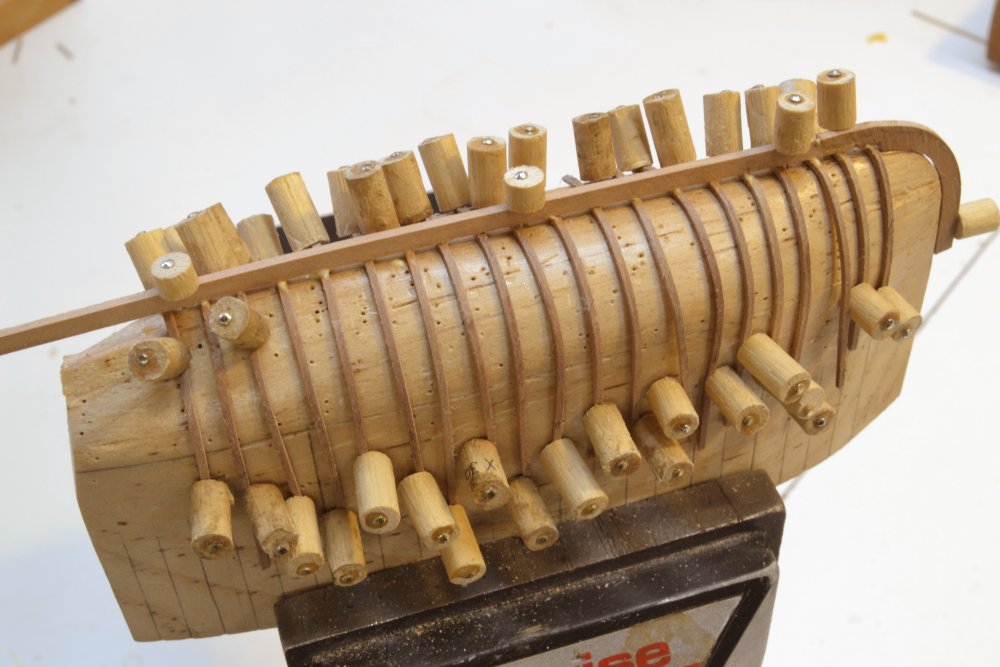
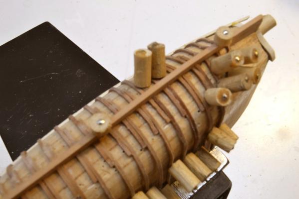
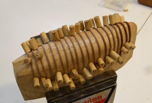
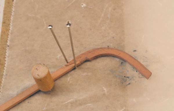
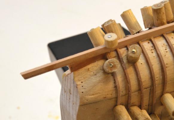
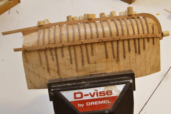
Young America - extreme clipper 1853 Part 146 – Ship’s Boats 2 In the last part I had just begun bending frames over the longboat plug for the first of the two longboats, so I will continue from that point, but picking up with longboat 2 from that same point. Longboat 1 is proceeding merrily along its way and I will catch up with that work later. In the first picture all the square frames on the port side have been soaked in water, bent over the plug and clamped down with the pin clamps. I found that soaking the .03” strips in water overnight was more than sufficient to make them flexible enough for this work. They were just left soaking until needed. Although pinned roughly in position these will be more accurately spaced at both the keel and the gunwale in later steps. This is the same plug used on Longboat 1, as evidenced by the pinholes. In the next picture the inside stem shape is being fitted to the bow of the plug. This was a case of matching up and sanding until a good fit was obtained. You may recall that the plug is shaped to the inside of the frames. In the next picture the outer curve of the stem has been cut after fitting the inner edge and the stem is being glued to the keel. This assembly was then glued to the frames as shown in the next picture. As this was clamped down with pins through drilled holes, the frames were spaced at the keel by eye. The upper ends are still doing their own thing. In the next picture a deadwood is being glued to the keel under the aft end of the plug. The next step was to bring the upper ends of the frames into line. This was done by nailing a strip over them at the gunwale as shown in the next picture. The lower edge of this strip (upper in the photo) corresponds to the top of the side. This strip put enough pressure on the frames allow them to be aligned and spaced at the top. Once this was done the uppermost hull plank could be glued to the frames. This is shown in the last picture. I used holly to plank the side. The planks are about 1” thick and 4 or five inches wide. The two longboats are carvel planked and will be painted. Note that none of the starboard frames have been installed at this stage. These will be slipped between the plug and the keel and glued to their partners along the frame floors. Thus each frame will extend from the top of the side, over the keel and to the turn of the bilge on the opposite side. This construction will be clearer in the next part. Ed


- 3,618 replies
-
- 35
-
-
- young america
- clipper
- (and 1 more)
-
Giampiero, you have been busy. Beuatiful work. The mattress makes me want to come in and lie down. Bravo. Ed
-
Looks fantastic, Micheal, in keeping with all of your work. Thanks for the additional data on the clamps. I will surely be trying these out - probablt smaller versions. Thanks. Ed
-
Johann, Your work on these boats is quite extraordinary - clean joints, excellent proportion, beautiful detail. Congratulations. Ed
-
Thanks everyone for the comments and likes. Johann, I have followed your work and your work on the boats. Your method looks familiar and your results are outstanding. I would like to do as well. Ed
- 3,618 replies
-
- 4
-
-
- young america
- clipper
- (and 1 more)
-
Perhaps . . . but what about bedding those pesky deck clamps?
-
The method described by Druxey - beveling on the finished hull or a section of it - was the method described in the Naiad book and in building the original model. The use of the patterns to align the two frames in each bend was covered pretty thoroughly, but these were not much used for beveling frames. In building Young America, frames were pre-beveled before erection and this was very successful in terms of accuracy and elimination of heavy hull sanding, but without the special provisions on both the drawings and in the process used for YA, pre-beveling can be risky. I did very little pre-beveling on the frames for the Naiad model. Rough pre-beveling on other parts, such as the bollard timbers was done and can be done from the patterns on one side only. Druxey, your suggestion of using the patterns on the wide side would work well for outside bevels but the inner bevels would need different treatment. Ed
-
Thank you, Erik and thanks for the likes. Druxey, try would be the right word. I bought an iron and tried a few pieces, but did not have much need for bending at the time. Perhaps the second longboat would be the time to do some more with it, especially on these small frames. Thanks. I may also adopt the method you used on the barge for the two cutters. Ed
- 3,618 replies
-
- 6
-
-
- young america
- clipper
- (and 1 more)
-
As I suspected. Do you glue them wet/damp, or let them dry in place first? Ed
- 641 replies
-
- 8
-
-
- greenwich hospital
- barge
- (and 1 more)
-
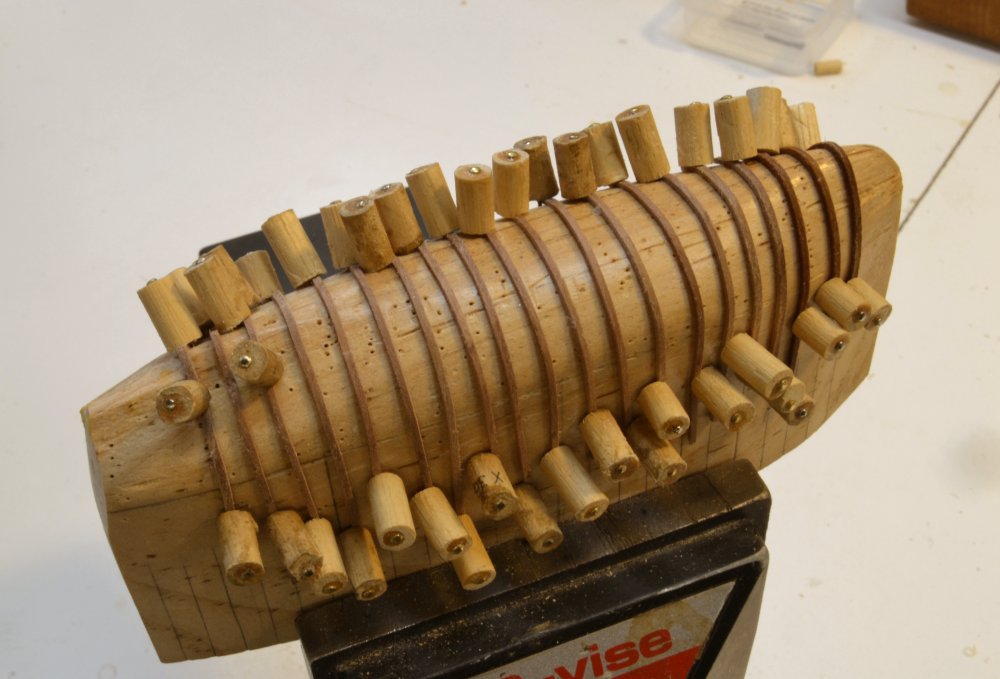
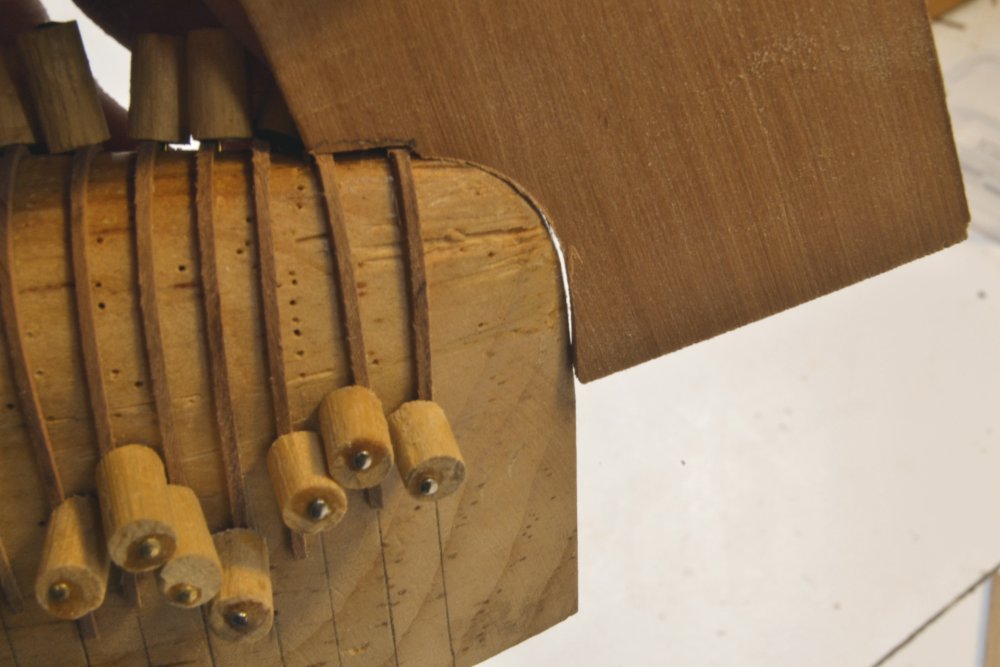
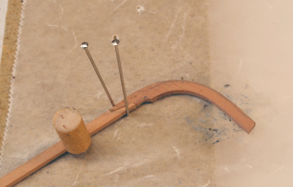
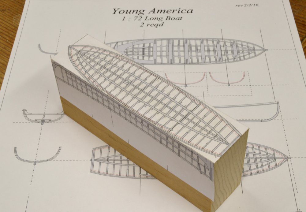
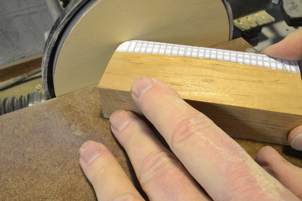
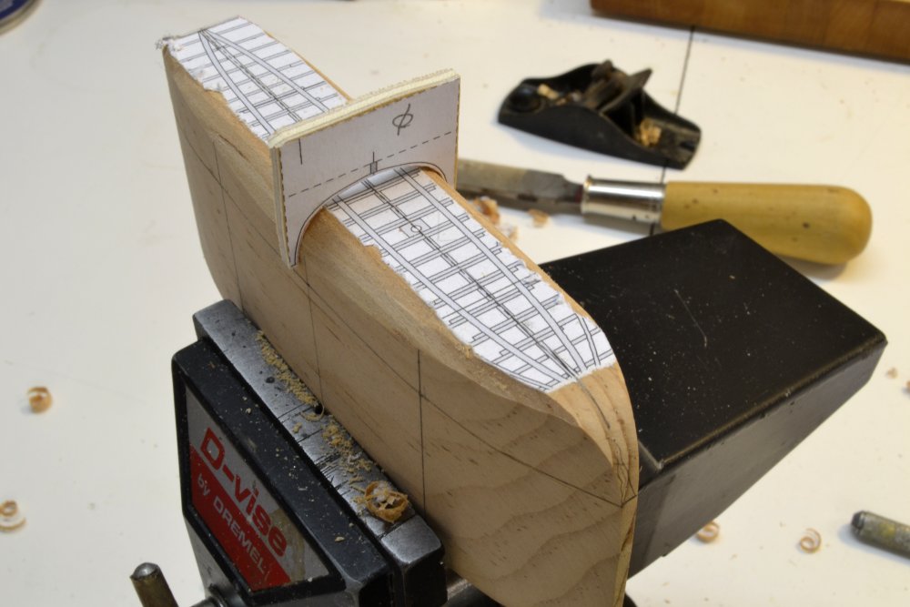
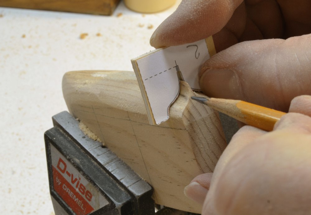
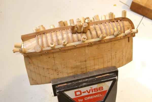
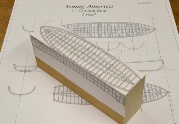
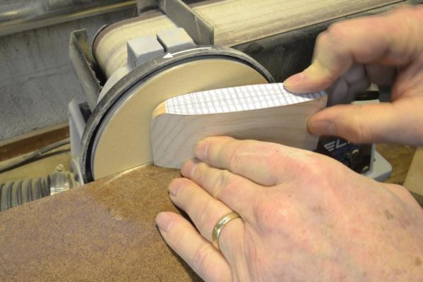
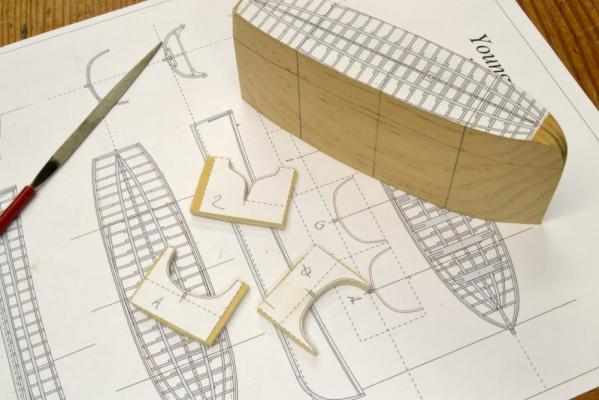
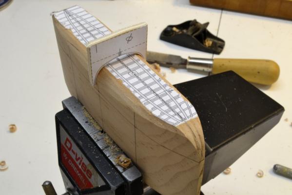
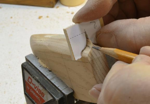
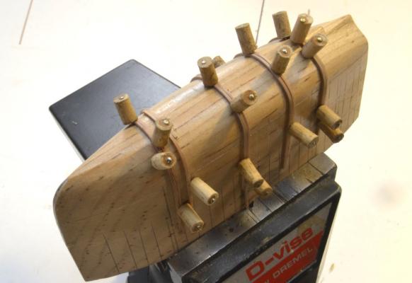
Young America - extreme clipper 1853 Part 145 – Ship’s Boats 1 Well, it is time to take the plunge on Young America’s complement of boats. I expect this to be a humbling experience in the presence of Druxey’s posts on his beautiful hospital barge and Michael Mott’s extraordinary boat work. However, I see no way out. There will be four boats, two 28’ (~4 ½”) longboats and two 25’ (~4 1/8”) cutters. The longboats are carvel built, as is one of the cutters. The other cutter is clinkered. Fortunately for me, three of the four will be stowed upside down on the skid beams, and the fourth, one of the cutters – work quality permitting - will be stowed on the quarter davits. I decided to start with one of the longboats. In the first picture, drawings of the framing plan and sheer elevation have been pasted to a block of soft pine. I expect to use the plug made from this block on both longboats. The first step was to shape bow and stern profiles as shown in the next picture. Then the sides by the same method. Lines were then scribed for the three station patterns that I used and for the top of the sides. The marked plug and the three pattern pieces are shown in the next picture. Pattern 2 is at the stern. I did not make a pattern for the line between midship and the stern. The patterns were taken at the inside of the frames. The plug was then given a fair shape using the three patterns as guides. In the next picture the midship shape is being checked after some initial planning and rasping. In the next picture the stern profile pattern has been given a coat of pencil lead so high points can be located. The pencil in the next picture is pointing to a high spot identified by the rubbed-off pencil lead. Work continued on the plug using rasps, files and sandpaper until the patterned shape and symmetric fair lines were obtained. The last picture shows the finished plug with the first of the two part frames curved and pinned in place. The plug was first given two coats of sanding sealer and then waxed. It was then marked with the frame lines on both sides to serve as rough guides for frame placement. Frames will eventually be spaced by eye when the keel and bulwark planks are added. The frames are held in position by the planking clamps I used on the decks of the POB model. The frames at this stage are about 2” (~.03”) square. Their molded breadth will be downsized a bit as they are faired during the planking process. The frame pieces were cut from straight-grained pieces of Swiss pear. For the bending of these I experimented with soaking the strips in isopropanol overnight, then bending and clamping down as shown. This worked satisfactorily, but perhaps more flexibility and less breakage would occur with boiling. Framing will continue in the next part. Ed

- 3,618 replies
-
- 36
-
-
- young america
- clipper
- (and 1 more)
-
Druxey, Fascinating and beautiful. Are the two clamps shown in the picture sufficient to hold the frames' shapes? Are these bent "dry" or are you bending them with heat or another method? Ed
- 641 replies
-
- 7
-
-
- greenwich hospital
- barge
- (and 1 more)
-
Fascinating. I bookmarked yo other site, so I can go through it at leisure. Thanks for posting. Ed
- 281 replies
-
- 1
-
-
- falls of clyde
- tanker
- (and 2 more)