EdT
-
Posts
2,214 -
Joined
-
Last visited
Content Type
Profiles
Forums
Gallery
Events
Everything posted by EdT
-
I was wondering the same thing, Remco. Most of the Naiad patterns show both front and back profiles. I normally sand or file to the outer profile first square to the face, then bevel to the inner profile - or nearly so, to leave an allowance for fairing. On the bollard timbers with their convex outer profiles, more allowance should be left. I will be interested in Gary's method for using patterns on both sides. I have done this in some cases by scribing index lines on the edges of the piece and using these to align the back side pattern - see the POB Young America posts on the stern pieces for this. Of course all this assumes that a mirror image or appropriate opposite pattern does exist. This is true for the Naiad bollard timbers - the other side's patterns can be used. Ed
-
Beautiful work as usual, Micheal. As an alternative to the glue mix, have you considered using shellac. I have thought of trying this, but have no done so. I was prompted to this by the thought of shellac sticks that are/were used for finish repair. Shellac adheres well, dries quickly, does not penetrate and is easily removed with alcohol. Just a thought. By the way, I love those clamps. I have tried without great success - or enough effort perhaps - to make clamps of similar type that would work well. Mine would need to be smaller and I may give them a try. Thanks, Ed
-
Thank you for this post, Roger. I am not familiar with the reference you cite, but will certainly get a copy. Ed ps. My search on Outline of Shipbuilding by T. D. Wilson did not yield an immediate result. Could you provide a link to the download site. Thanks.
-
HMS Naiad 1797 by albert - FINISHED - 1/48
EdT replied to albert's topic in - Build logs for subjects built 1751 - 1800
Fantastic, Alberto. Simply fantastic. Ed- 653 replies
-
- 10
-

-
Gary, You are not experiencing anything that would be out of the ordinary for any of us. Except for point six, which I am simply far too undisciplined to do, I agree with every other point - in fact, most emphatically. I would emphasize that it is very important not to over shape or try to finish sand pieces prematurely. I restrict the use of the #11 blade to cutting patterns. Also, I do not recommend leaving pieces over-sized - that is more than about 1/64" outside the patterns - with the idea of finalizing their shape later by sanding. Let the patterns do their job in setting the shape. Virtually all the Naiad patterns have front and back profiles that I found to be quite accurate. (If not, I hopefully fixed them in final revisions.) I think if you adopt this approach, the bollard timbers will fall into line. The forward inside edges matched to the forward outside edges marked (i.e. scribed through its pattern.) on the next inside piece is the key. I do not wish to make this sound too easy. Authentic full framing is a challenge - otherwise why do it. Good luck. I think it looks great so far. Ed
-
Thanks, Bob. I will issue revisions, of course. I keep telling myself that in almost 300 drawings, checked only by me, that errors are inevitable, but I would still prefer not to have them. Your attention to this level of detail is most helpful. Fortunately, most have been in the "typo" category. Thanks, Ed
-
I assume that the plans you have are those from Seagull Plans, drawn by the late Bill Crothers with some details drawn by, I believe, Thomas Hornsby. Bill concluded that the rail was brass, quite common during the period for rails of this type. The primary, evidence, as I mentioned in the post, for me and for Bill ( I asked him), is from the surviving photo taken from the starboard quarter. The rail is almost but not quite invisible in my copies of the the photo. Bill had access to the original prints. This evidence rules out, for example wood stanchions and a heavy wood rail - at least at the time of the photo - which is my chosen period for the model. I considered that the rail itself may have been wood of lighter section, mounted on metal stanchions. In the end, partly because of my deep respect for Bill's meticulous research, I followed his lead. There is also no trace of a center rail. I share your feelings about safety of the rail - to say nothing of the dangers of the completely unrailed forecastle. Perhaps netting was rigged when at sea. There are inevitably items on all these ships that could be challenged technically. With my background and natural inclination I often find it hard to resist re-engineering things that are not clearly documented. Its a bad habit. We are modelers, not designers. Sometimes design is unavoidable due to lack of definition, but in the case of the single brass rail, I think it is reasonable given the evidence. Ed
- 3,618 replies
-
- 12
-
-
- young america
- clipper
- (and 1 more)
-
Druxey, you've shattered my illusion. I thought mishaps like that were reserved for us mortals. I have done the same thing twice this week on the first of YA's boats, but that is par for the course for me. Fortunately, you have the perfection of the product to compensate. Beautiful, inspiring work. Ed
- 641 replies
-
- 7
-
-
- greenwich hospital
- barge
- (and 1 more)
-
Stunning interior photos, Gaetan. The work is a masterpiece. Ed
- 728 replies
-
- 2
-
-
- le fleuron
- 64 gun
- (and 1 more)
-
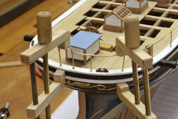
Young America - extreme clipper 1853 Part 144 – Monkey Rail 2 Happy Valentines Day, everyone. After making and polishing the rail stanchions holes were measured out and drilled in the center of the main rail and in most cases down into the toptimbers below. The stanchions were then inserted into the holes for a depth check. A single rail section for each side was then curved to match the poop profile. The stanchions were then removed from their holes and threaded on to the rail in order. The next picture shows the next step – epoxy gluing the stanchions into their holes. The end of the rail was first inserted into the inverted U bracket at the stern. All of the stanchions were then inserted into their holes, then lifted for gluing starting at the stern. The clamps in the above picture are lightly pressing the stanchions down where needed until the epoxy sets. The next picture shows the last stanchion on the starboard side being glued. The rail was crimped in the aft stanchion then touched with a drop of CA glue. The others are free to move along the rail at this stage. The forward end of the rail was bent to the athwartship direction at the foremost stanchion as shown in the next picture. The stanchions along the breast beam were then glued into place with the rails inserted. In the picture above, the glue has dried and a section of stair rail is being fitted into the lower ball on one of the stanchions at the top of the stair. The next picture shows the stanchions loosely in place on the port side. In this picture the port rail has been curved to shape and is ready for installation. The last two pictures show the completed monkey rail. This last picture was taken before final straightening of the stanchions on the near side. Once everything was adjusted the top balls were crimped with pliers to hold them in place. The rail is, of course, quite exposed and susceptible to damage by careless leaning or bumping. I am trying to sensitize myself to this new problem. The days of turning the model over and shaking it to remove debris are over. Ed


- 3,618 replies
-
- 56
-
-
- young america
- clipper
- (and 1 more)
-
I like your idea for mounting the cutter, Micheal - and the model looks as fantastic as usual. Ed
-
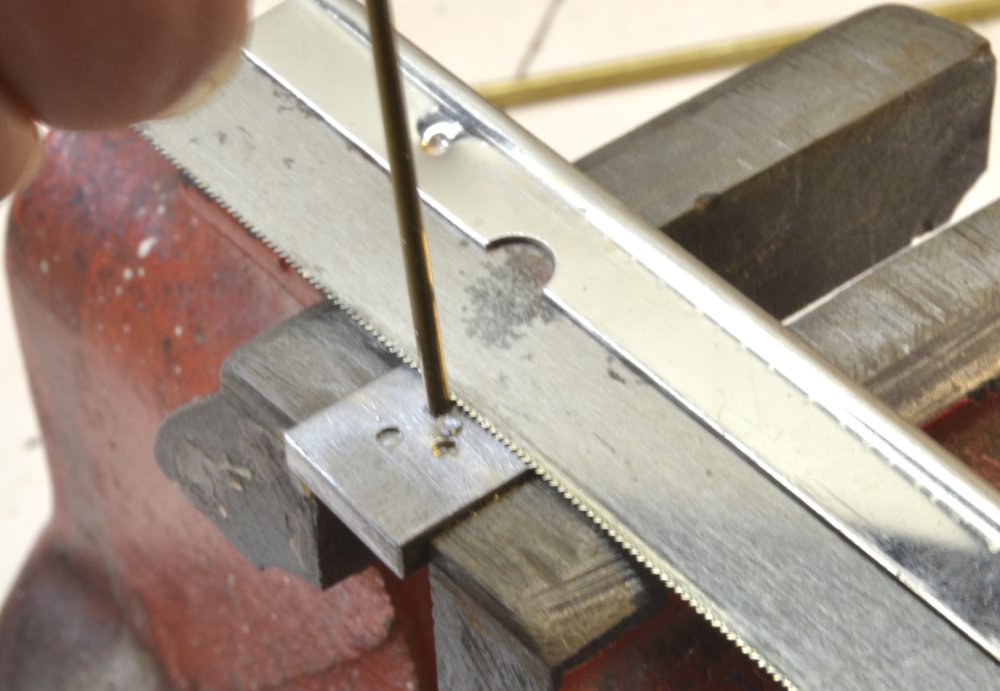
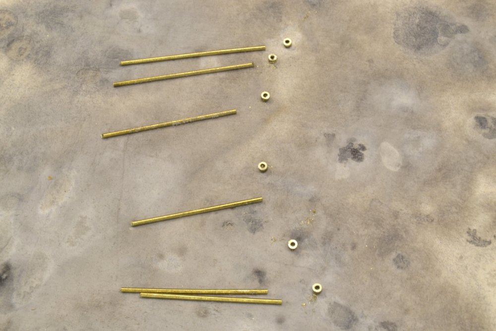
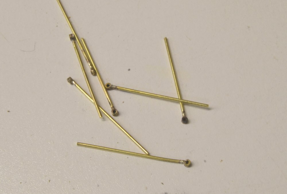
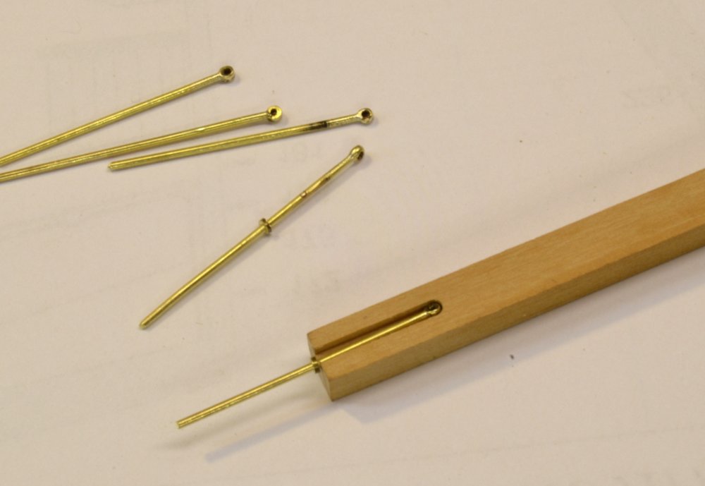
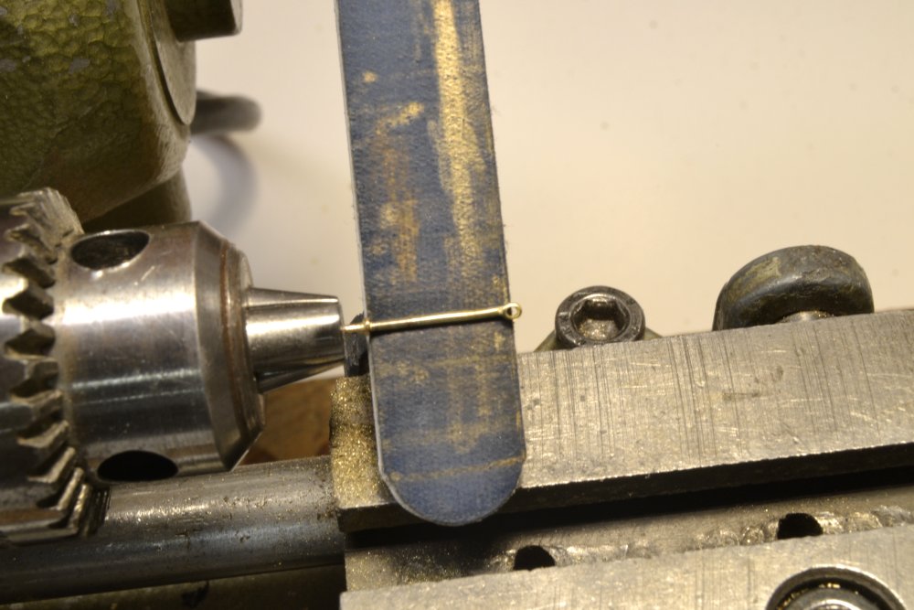
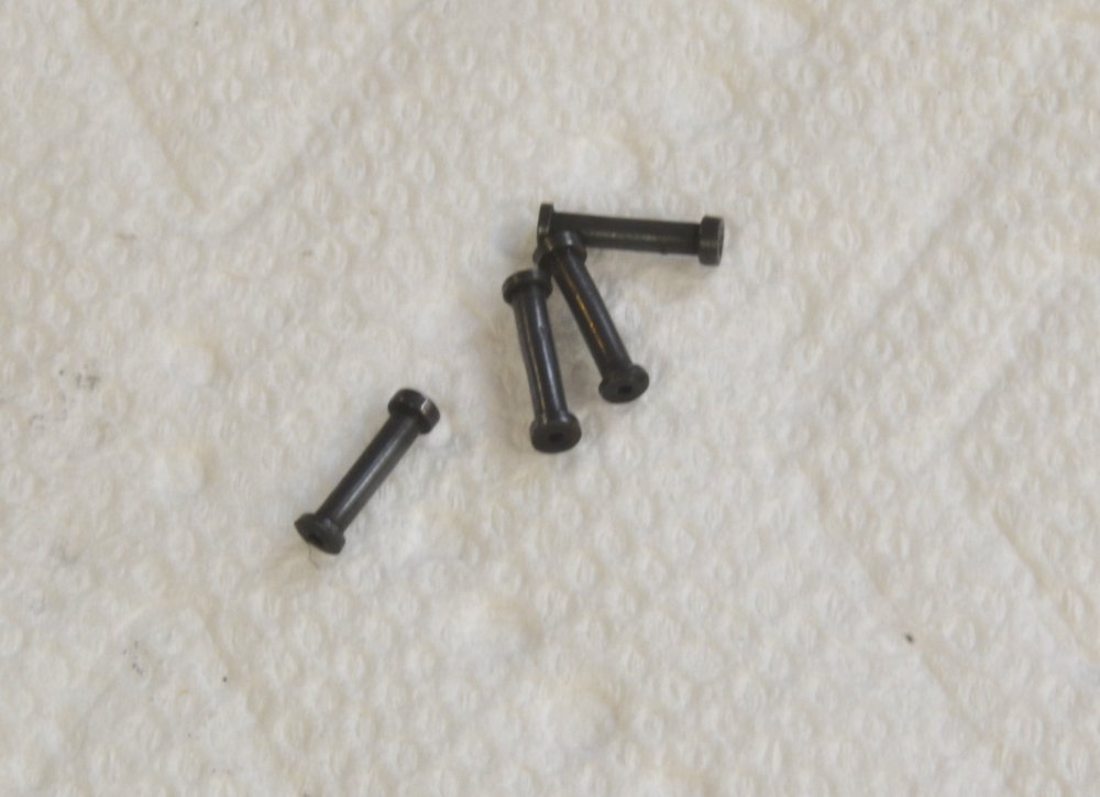
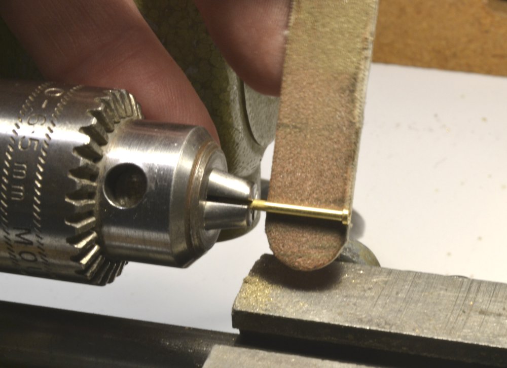
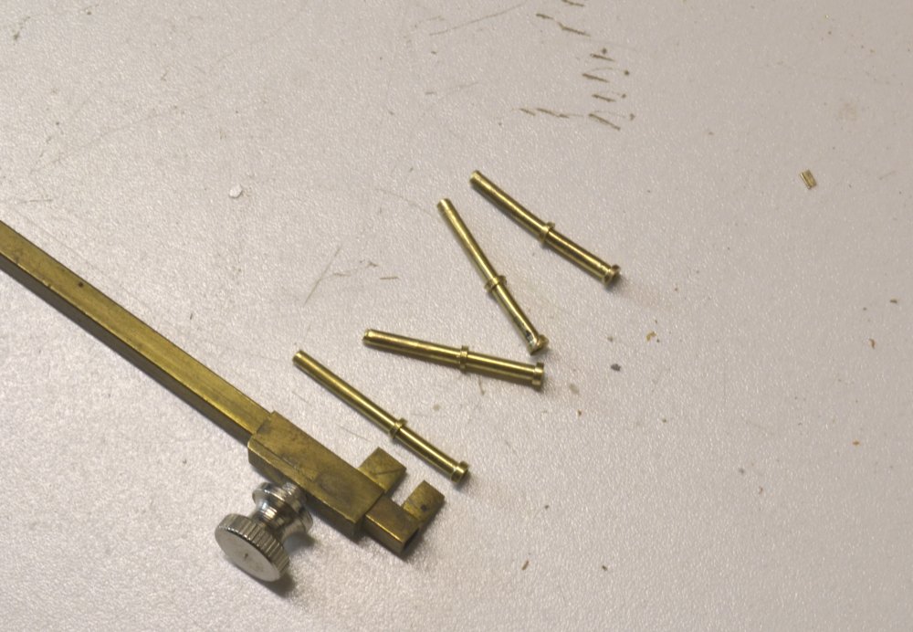
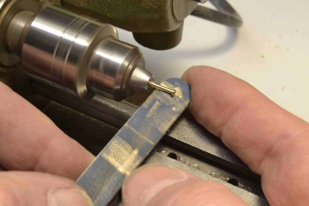
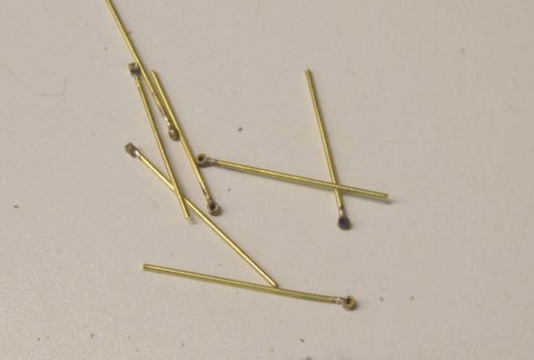
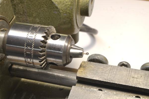
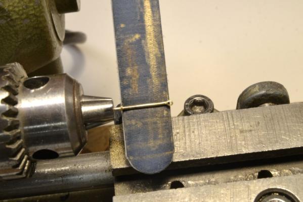
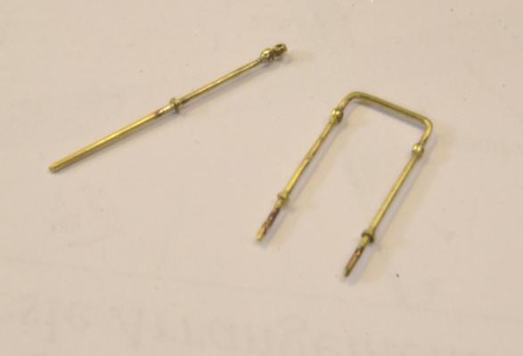
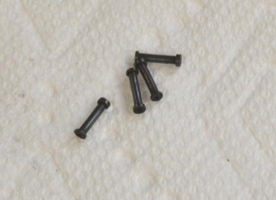
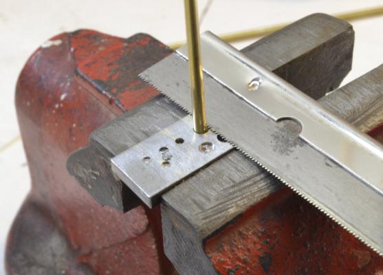
Young America - extreme clipper 1853 Part 143 – Monkey Rail 1 The two surviving pictures of Young America again provided the basis for the brass rail design used on the model. The rail is just discernable in the picture taken from the starboard quarter. From this it is clear that it was not of heavy or ornamental wood construction and equally clear – at least to me and I am happy to say, Bill Crothers – that it was a single, slim rail. By the way, it is also very clear from this picture that the poop deck is at the height of the main rail and not a few feet below as shown on some models – including the builder’s half model in the Smithsonian. Either that, or the people standing on the deck were on well-hidden stilts. I suspect that the need to have good height in the aft cabin area led to this feature being incorporated before actual construction, perhaps by the owners. Anyway, based on the picture and Bill Crothers’ interpretation, I elected to incorporate a single brass rail about 3 feet above the deck supported by cylindrical brass stanchions. These have a ball-shaped top to pass the rail, and flanges at the base that rest on the main rail. The first picture shows the method used to cut both the top fittings and the lower flanges. The cutting guide used on the skid beam stanchion flanges was used for this. The picture actually shows one of the 2” thick flanges being cut off. The tops were cut in 3” sections using the hole covered by the saw. The next picture shows top pieces and stanchions almost ready to be soldered together. The next picture shows the first step of the assembly with the tops silver soldered to the posts. The soldering unfortunately softens the wire somewhat so straightening is required – initially and whenever I lean on the finished rail – a habit I am diligently trying to correct. The tops were then rounded off and polished in the lathe with files as shown below. The next picture shows the addition of the lower flanges. The wood guide was used to ensure uniform height to the posts – and of course the rail. After setting the flanges at the correct height, these were soldered on. The next picture shows the final finishing and polishing of one of the stanchions. Chucking the complete stanchion assembly in this step was the reason for the excess length in the initial pieces. After filing a fillet on the top of the flange and removing all traces of solder and scale, fine abrasive polishing sticks were used to bring up the luster of the brass. Some special stanchion pieces were required and two types are shown in the next picture. The stanchion at the top has two top fittings set at right angles. These will be set at the head of the steps to the main deck to support both the athwartship rail sections on the breast beam and also the stair rails. The lower piece was shown earlier in position at the stern. I do not know the purpose of this higher section, but it serves as a convenient start point for installing the rails, as will be seen in the next post. Ed


- 3,618 replies
-
- 43
-
-
- young america
- clipper
- (and 1 more)
-
Sorry to be just catching up, Hakan. Its good to see you posting again - and with such an interesting project. I like the simplified versions of the clamps you have made - a great idea to reduce the complexity and still maintain the flexible nature of the clamp. Please tell us how well your steam box works. Cheers, Ed
-
Richard, unfortunately it is difficult to make an accurate prediction on the next volume. I believe it will be no less than two years considering the amount of modeling needed plus the time to write and produce the book. The publication date will also be subject to the Seawatch publishing schedule. I can tell you that both Seawatch and I want to get the book out as soon as we can. Ed
-
Ingenious and very effective method on the mast rings, Micheal. They look terrific. Who would have thought? Ed
-
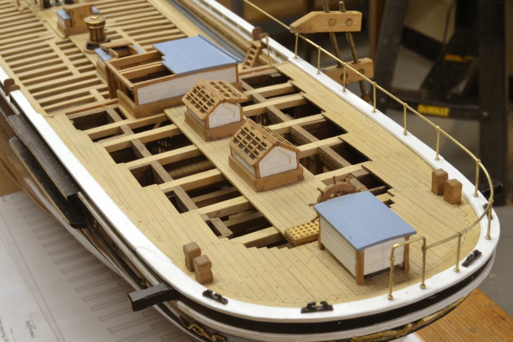
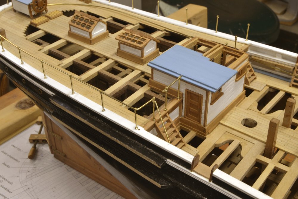
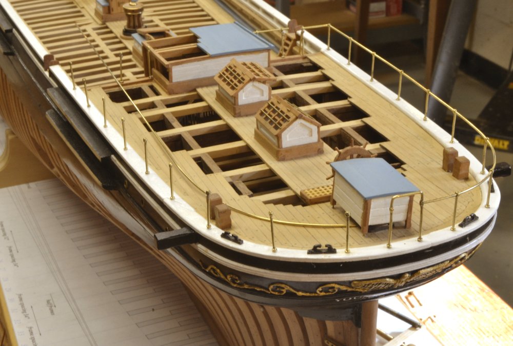
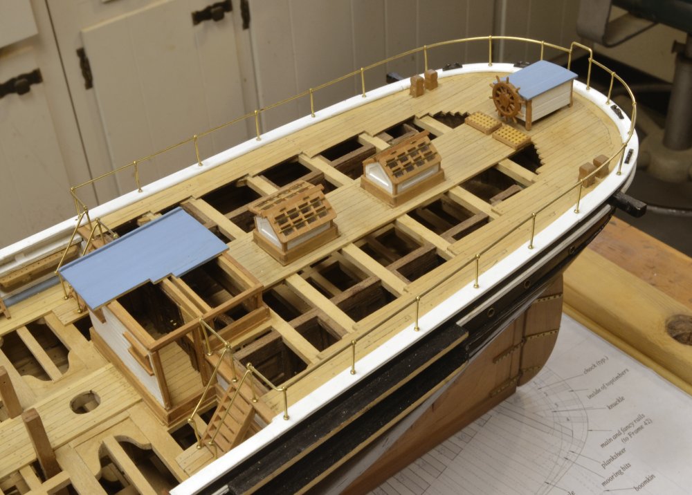
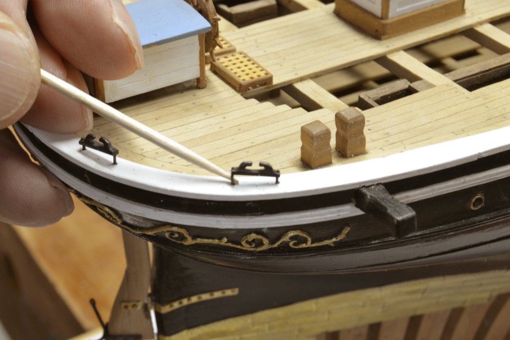
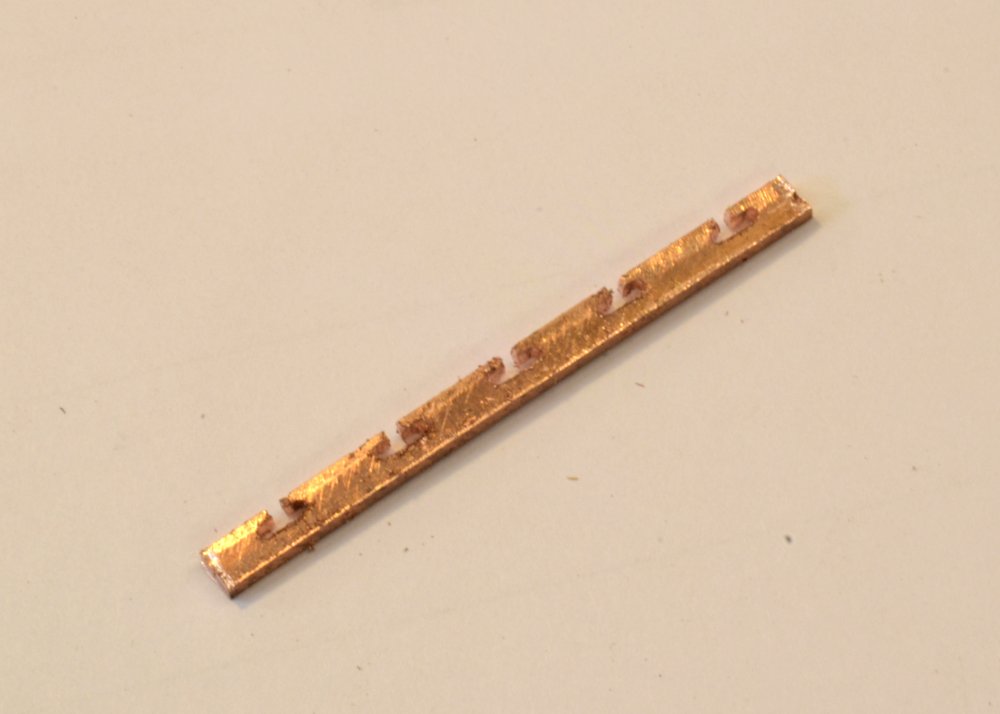
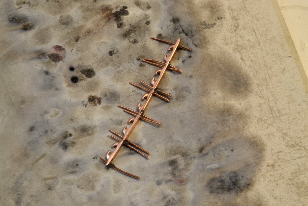
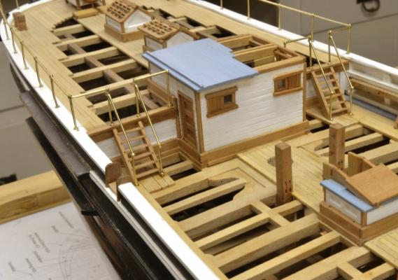
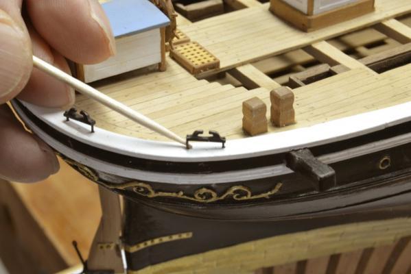
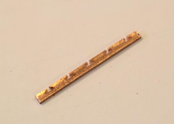
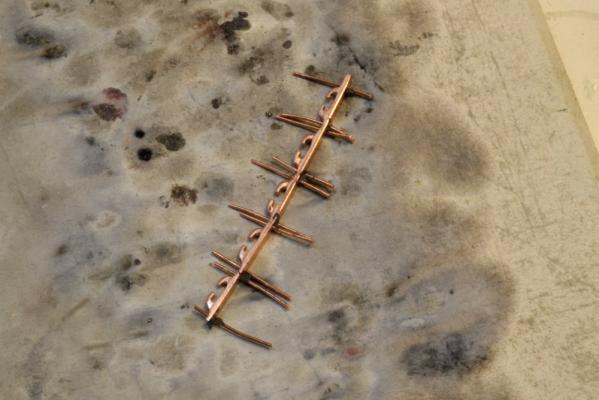
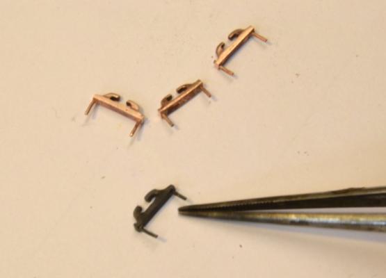
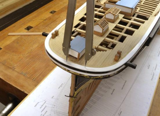
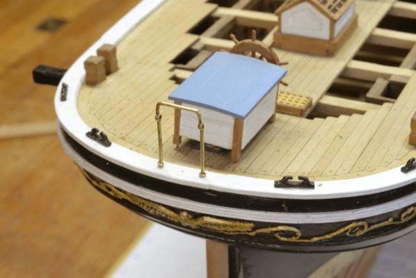
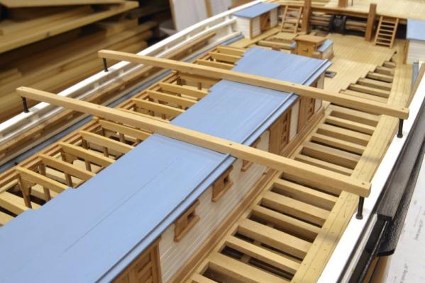
Young America - extreme clipper 1853 Part 142 – Mooring Chocks The next planned item of work was to install the brass “monkey rail” that surrounds the poop deck. I do not know the origin of the term. However, since the four large chocks that control the route of the mooring lines through the rail from the dock to the mooring bitts are below that rail, they needed to be slipped into the queue and installed first so that holes for their bolts could be drilled. There are four of these at the stern and four at the bow. The first picture shows these being installed on the starboard side of the stern quarter. A small dab of epoxy is being applied in the picture. The chocks – sometimes called “comb cleats” – and their bolts were made as integral assemblies as described below. The chocks and the bolts were made from copper. I prefer this material to brass because I find it easier to blacken using liver of sulfur solution. The first picture shows a length of copper bar with shapes for several chocks partially cut. The first step in making these cuts was to drill two spaced holes for each chock. The tops were then cut through with a jeweler’s saw. In the next picture a round, spiral-toothed blade is being used to shape the inner lines. The outer contours of the chock cleats were then filed out. In the next picture the rounded shapes of the chock cleats have been filed and polished, holes have been drilled for the bolts, wire bolts inserted, and the strip of chocks readied for soldering. Copper-phosphorus solder was used for this because it blackens well with LOS. The finished stern chocks are shown in the next picture. The bolt heads have been cut back and one of the chocks has been blackened. In the next picture the locations of the chocks are being laid out with dividers. Bolt hole spacing was also set with dividers and the holes drilled through the main rail. In the last picture the four chocks have been installed. The last picture also shows the aft, central section of the monkey rail temporarily positioned and in need of a bit of straightening. I also not in this picture that the helm enclosure – temporarily fitted at this stage was a bit askew on its pins when the shutter snapped. Work on the brass monkey rail was now able to proceed and will be described in the next part. Ed
- 3,618 replies
-
- 38
-
-
- young america
- clipper
- (and 1 more)
-
Thank you, Dave. I shoot in available light, using auto aperture priority, with aperture closed down to maximize depth of field. Tripod is a must because small aperture requires slow shutter speed. Some pictures are then auto color balanced to make them more natural and to compensate for the florescent shop lights. Ed
- 3,618 replies
-
- 7
-
-
- young america
- clipper
- (and 1 more)
-
Bob, Save your gasoline and search online. I use a product called amnesia. Here's an eBay link to the 20 lb test. There are several sizes. http://www.ebay.com/itm/AMNESIA-MEMORY-FREE-FISHING-LINE-20-LB-BLACK-SS08420-/120483332146 I notice that there are now other maybe imilar products. Search for black monofilament.
- 3,618 replies
-
- 4
-
-
- young america
- clipper
- (and 1 more)
-
Gary, I cannot add much to the process described on p.38 of Naiad, Volume I, but you do need to start with the right ingredient. Here is a link to the product I used for both Naiad and Young America. I used Raw Umder. This will make a dark brown glue. http://www.jerrysartarama.com/discount-art-supplies/oil-color-paints-and-mediums/dry-pigments-and-binder-mediums/sennelier-artist-dry-pigments.htm Unfortunately, local art dealers tend to have a rather thin inventory, which is understandable considering the vast array of products available. The products you tried presumably had an acrylic binder, meaning they are formulated with an acrlyic emulsion to be compatible with acrylic or other water based paints. This probably makes them incompatible with the PVA Titebond glue. Even if the product mixes well it will certainly impair the glue properties. You want to disperse the dry pigment into the glue, so it will become the binder. This requires pure dry pigment with no additives. The key word here is "disperse". The process in the book suggests how to get a homogeneous blend. That is the reason for starting with a small amount of glue and adding a bit of water to make an initial syrup. Otherwise permanent lumps will form when the powder is added to the full amount of glue at once. If I could add one comment to that, I would say less pigment could be used. Probably 1-2 teaspoons to a 6 oz. glue bottle is enough. The mix should be about the color of purchased chocolate milk. It will dry very much darker. While I have experienced no evident loss of glue strength, less pigment will have less potential ill effects. If you want to add more, remember to make some more syrup first. Good luck. Ed
-
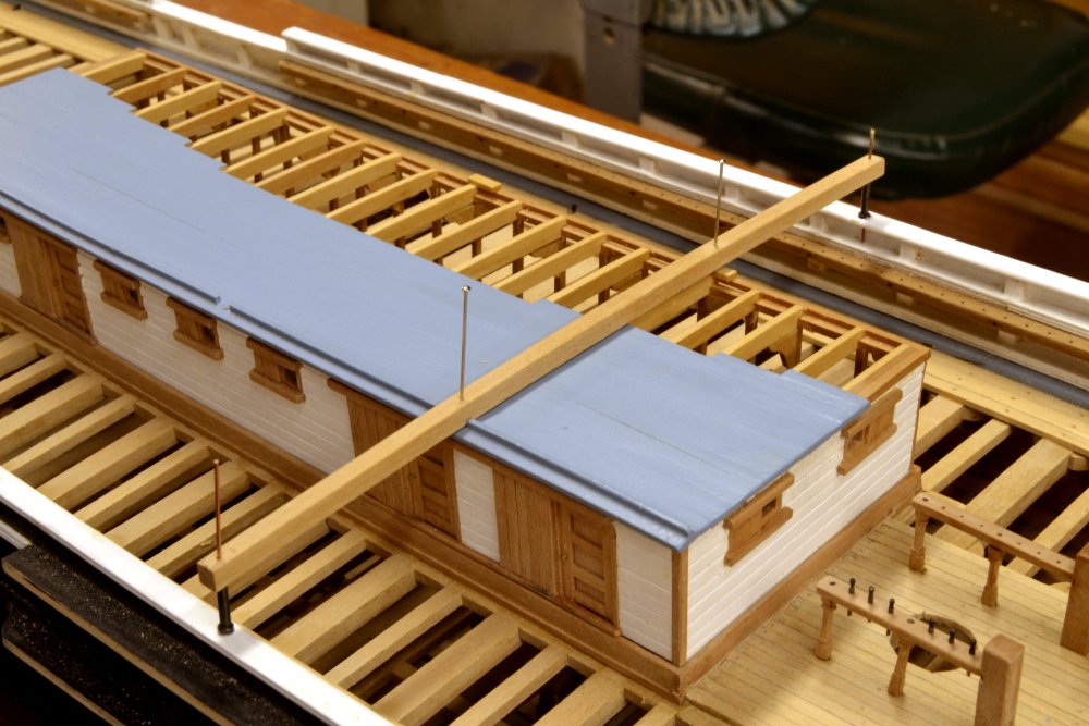
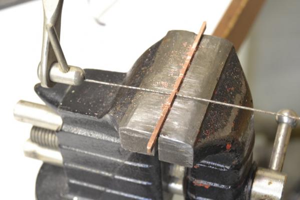
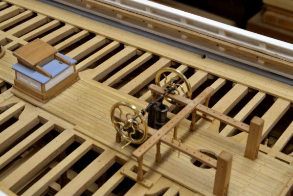
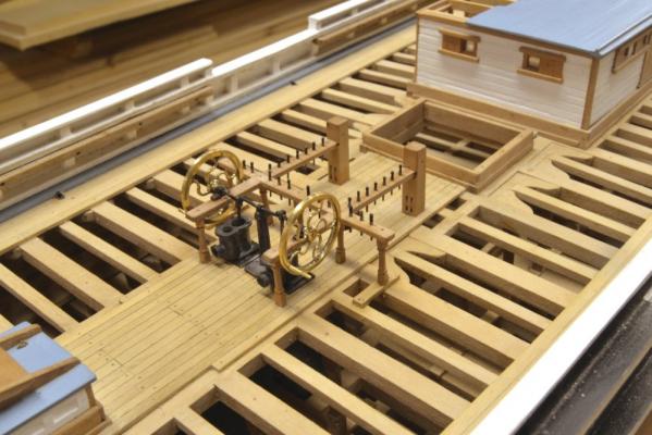
Young America - extreme clipper 1853 Part 141 – Skid Beams Young America’s four boats were stored on skid beams that extended across the breadth of the ship over the main deck cabin. These were supported by stanchions off the bulwarks and by the cabin structure. The first picture shows the completed installation of these beams. The beams have the same round up as the decks. The supports at the bulwarks are iron. I made these as flanged cylindrical posts. The next picture shows the stanchions after blackening. These were made from brass tube and flanges cut from the next larger size of tube. The next picture shows the method used to cut the flanges. To size the thickness of the flanges a steel cutting gauge was used. This has a number of milled holes to fit two sizes of tube. The holes were bored to depths of 1”, 1.5”, 2” and 3” for different uses. In the picture the flange tube is being cut by hand with the tube held down in the 1.5” recess. After cutting, the disks are filed clean while in the recess. The flanges were then silver-soldered to a length of smaller tube. After pickling they were cleaned up and polished in the lathe as shown below. Flanges were then made and fitted to the opposite end as shown below. The flanges were set at the required length taken from measurement on the model using the depth gauge shown in the picture. After soldering and pickling, the second flanges, the pieces were returned to the lathe for final polishing as shown below. The stanchions were then parted off in the lathe, degreased and blackened. The last picture shows the beam installation in progress. Indexing pins were placed to hold the beam in position. Copper wire “bolts” were then epoxied through the beam and stanchions and into the bulwarks to permanently secure the ends. Similar bolts were then installed into the cabin structure. One more of the several deck installations now complete. The next order of business was more challenging - the brass monkey rail around the poop deck at the stern. Ed


- 3,618 replies
-
- 36
-
-
- young america
- clipper
- (and 1 more)
-
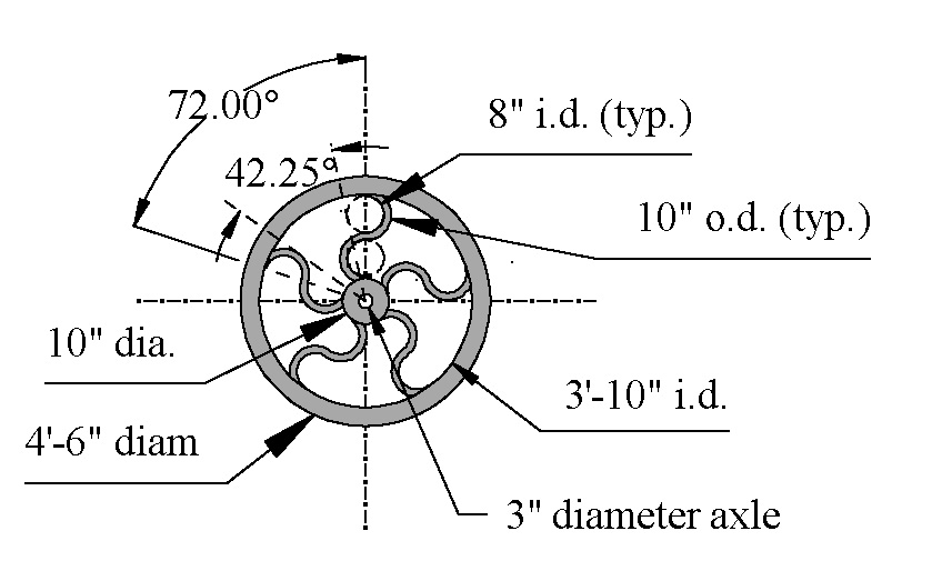
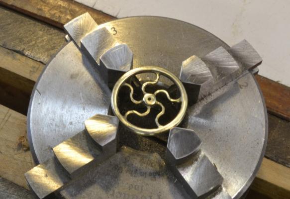
Thank you all so much for the likes and comments. Again, I am overwhelmed and grateful. I’d like to respond to some of the comments: Pete, I would like to have Webb back for a few hours. I have a lot of questions. Bob, I think you will find the Grobet files a good investment, though they may seem like a luxury. I am glad the pin-indexing process is working for you. I am very proud of it, but I can assure you, all processes can be improved. I hope that when (not if) you find some improvements, you will share them with us. Nigel, I am glad you are enjoying the book. On the color pictures, I agree that some would be nice and we did add a color section in Volume II of Naiad. “Some” is the operative word here. Good color pages are very expensive, so more than a few would price the book out of reach. Fortunately, hundreds of colored pictures have been posted on this build log and can be a useful supplement to the book. Greg, I am glad you noticed the issue, though it was not a serious impediment – more like a good opportunity for a careless mistake. The geometry was the key to making this visually symmetric. Here is a piece of the drawing that shows the role of the 8" i.d. circles in shaping the spokes: Ed

- 3,618 replies
-
- 21
-
-
- young america
- clipper
- (and 1 more)
-
Great job, Gary. I'm loving it. Ed
-
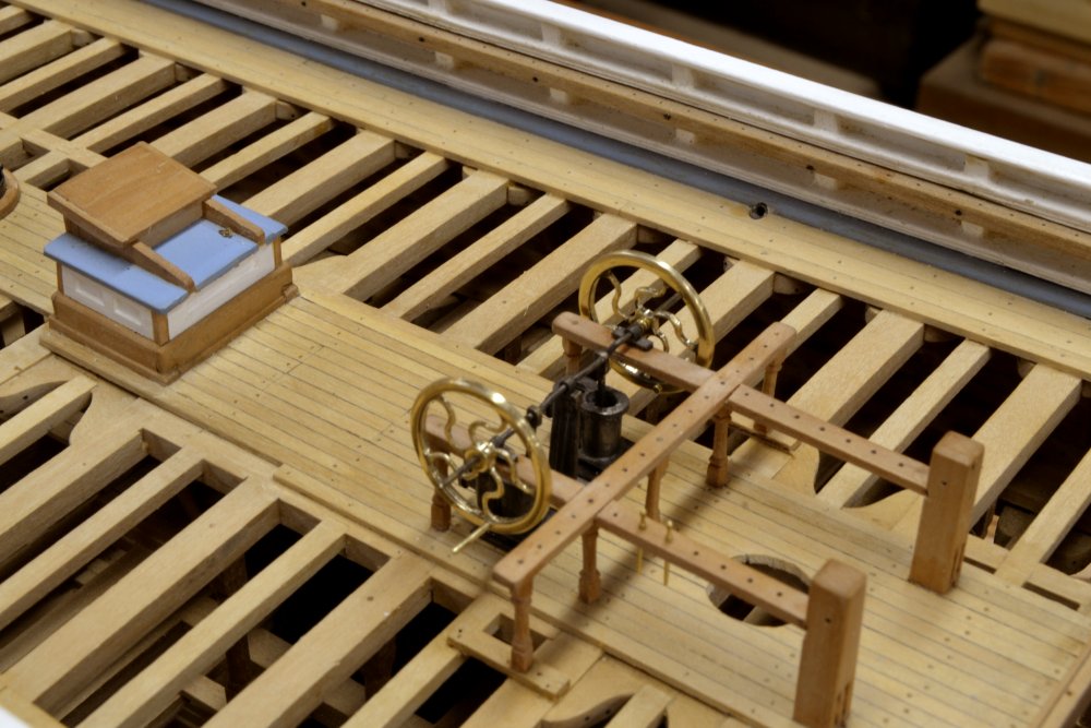
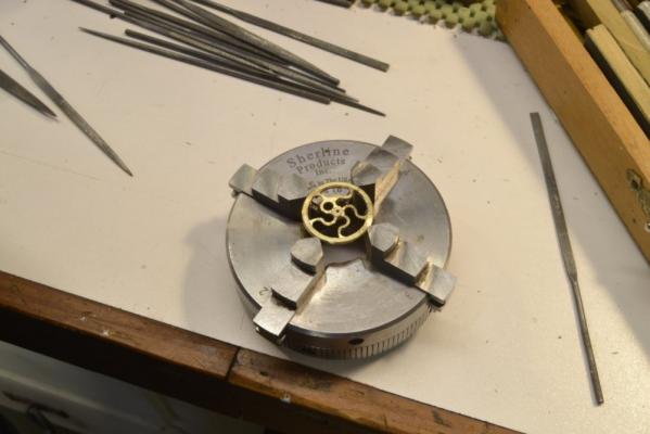
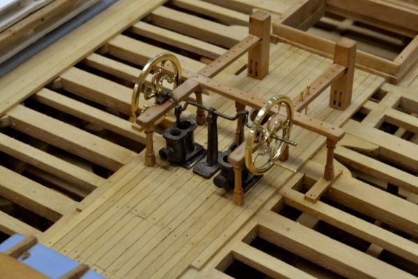
Young America - extreme clipper 1853 Part 140 – Bilge Pumps 4 In the last part the basic geometry of the pump flywheels was machined into one of the wheels. With the symmetric geometry of that wheel established, the remaining work on the wheel was done by hand with small files (serrated and diamond grit) and polishing sticks. To take advantage of the wheel being chucked, one wheel was completed at a time. In the first picture the machined and still chucked wheel have been removed from the mill together so the chuck could be used to hold the wheel for the hand filing – as shown in the first picture. Starting off with this was a bit confusing until one filed out spoke set the pattern. The basic shape of the spokes was first filed out without doing any rounding. The next picture shows this still incomplete step. There is still some material to remove between the spokes. Once the parallel curved lines of the spokes were established, each was rounded. The wheel was flipped in the chuck to file from the other side. The polished wheel is shown below. The second wheel was then made by the same process. Each rim was then drilled to fit a crank handle. The inside end of each of these was peened over to hold it in place – avoiding soldering. I had originally intended to blacken and perhaps paint the flywheels but once made I decided that their shape could best be appreciated by leaving them as polished brass – call it artistic license. The next two pictures show the finished wheels mounted on the crankshaft. Small sleeves between each wheel and its bearing keep the wheel clear of the fife rails. The wheels were finally glued to the shafts with epoxy. The last picture was taken after cutting off the excess shaft material and after the fife rails were fitted out with their complement of belaying pins. All the work of the last few months has involved a series of discreet tasks –cabins, companions, windlass, capstans, and now the pumps – that need to be completed before I can get “off the deck” with the masts and rigging. I am impatient to get to that, but there are several more “deckbound” tasks to complete yet. Ed

- 3,618 replies
-
- 55
-
-
- young america
- clipper
- (and 1 more)