HOLIDAY DONATION DRIVE - SUPPORT MSW - DO YOUR PART TO KEEP THIS GREAT FORUM GOING!
×


EdT
-
Posts
2,213 -
Joined
-
Last visited
Content Type
Profiles
Forums
Gallery
Events
Everything posted by EdT
-
Thank you, Nigel and Frank and others who have clicked on the "like" box. An interesting and perceptive question, Frank. I'd like to think rapid progress is not due solely to careless rushing. Until after the conference I had not worked on the model since April, so some of the recent progress may be attributed to enthusiasm to get back on it. Actually I had some of the main cabin walls fabricated - but not installed - before Mystic. Your suspicion about the drawings is the perceptive part. While not the major factor in this recent detail work, I do very much think about what goes on the drawings and how that fits together with and supports the actual work. Drawings are part of the process, so the content needs to do its part and not just fit some standard traditional format. My best example of this is the pin-indexing on the frame drawings for this ship. This saved many, many hours not only in frame fabrication but also in the speed with which pre-bevelled frames could be erected - to say nothing of eliminating the tiresome usual hull fairing. There are other examples. One that I am very excited about , that I hope will appear later, is the use of a common, universal rigging line number that will identify the details of the line, belaying points, routing, fairleads and other connections - eliminating separate belaying pin numbers and adding a lot more rigging information to the various drawings. You have obviously pushed one of my hot buttons. To be honest about the current work, some - like the wheel - required very accurate drawings before starting. Some - like the framing of the large deck structures - was more of an iterative process, with the design evolving together with the work. Some of the rapid progress, I am sure, is do to the fact that I do not like to fuss a lot - as much as it might improve my work - it's not in my genes. Ed
- 3,618 replies
-
- 14
-

-
- young america
- clipper
- (and 1 more)
-
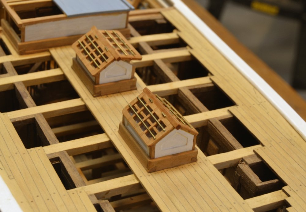
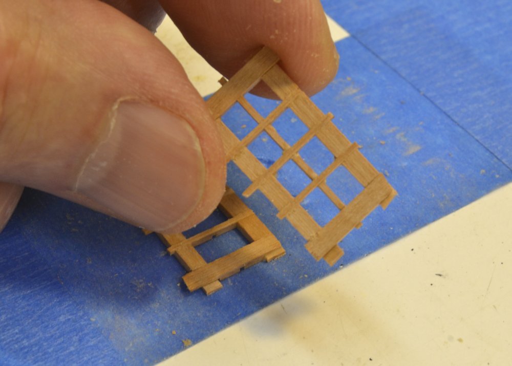
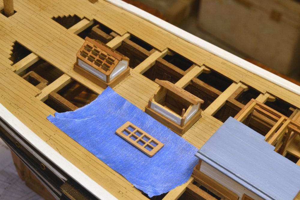
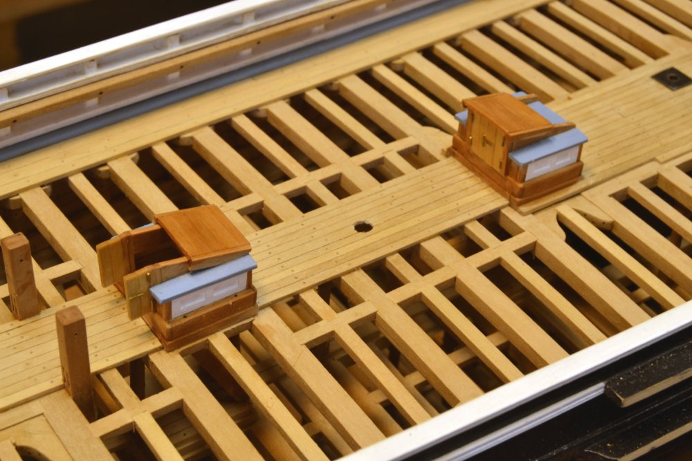
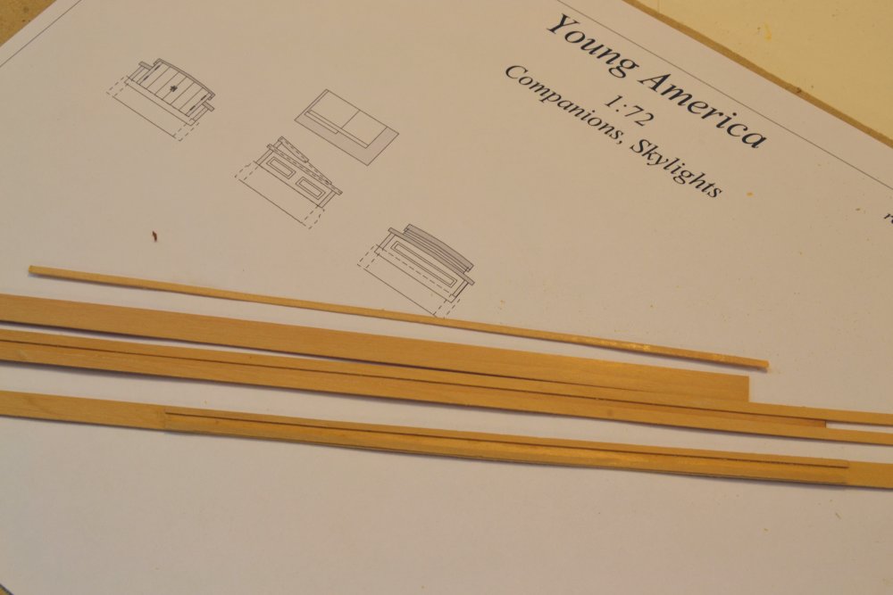
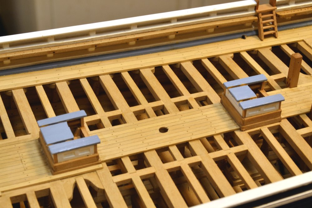
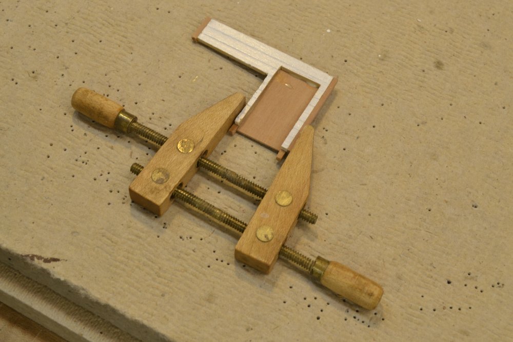
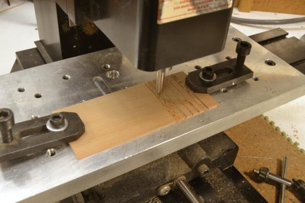
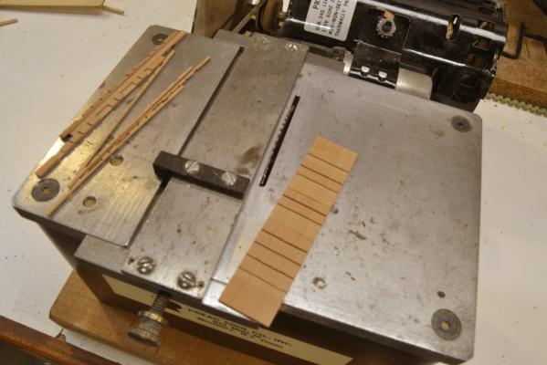
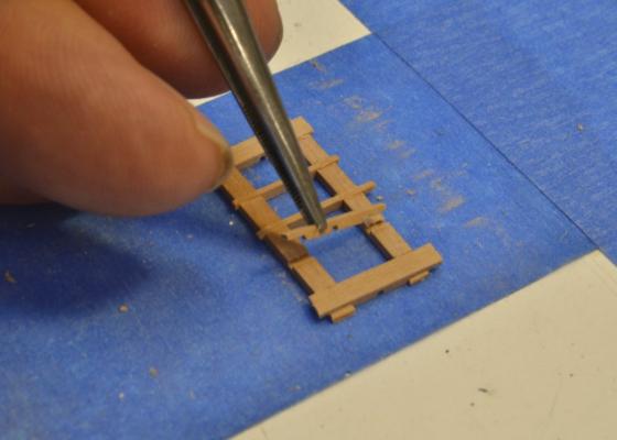
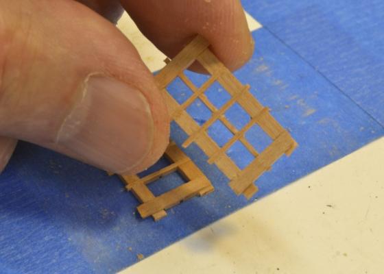
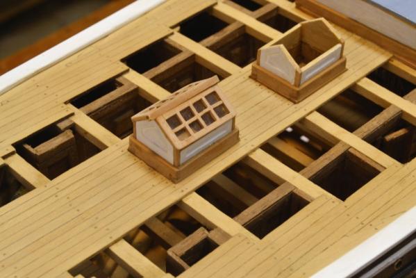
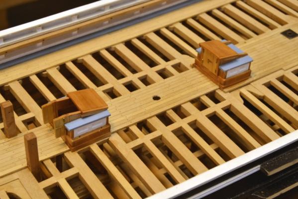
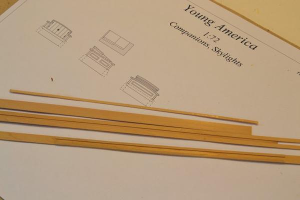
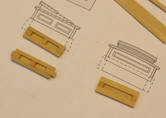
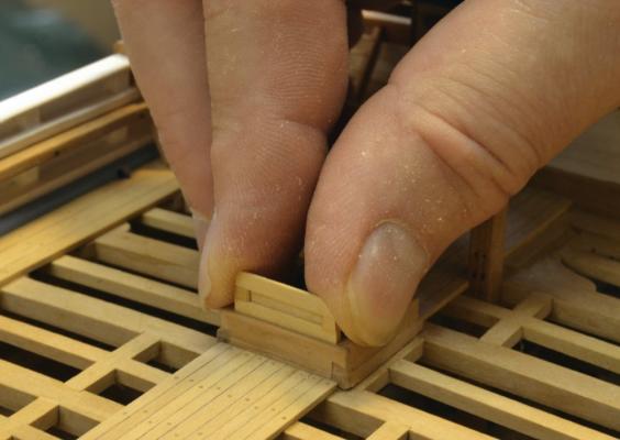
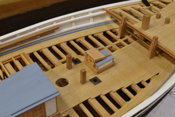
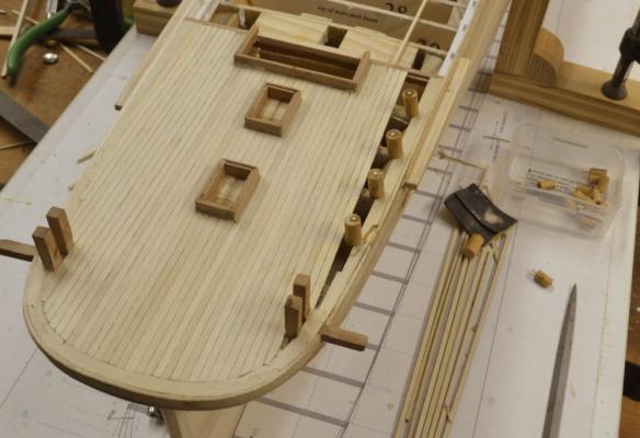
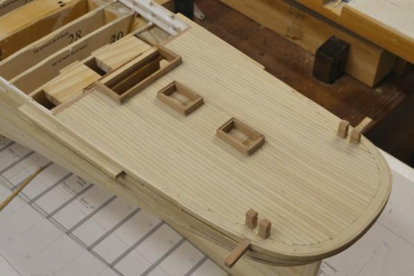
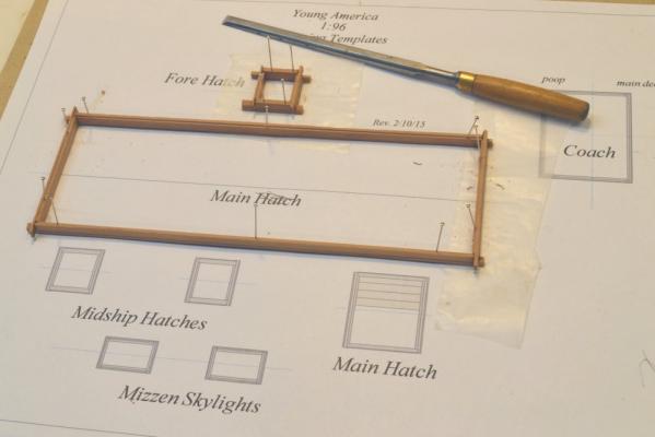
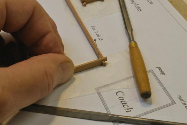
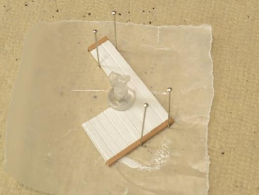
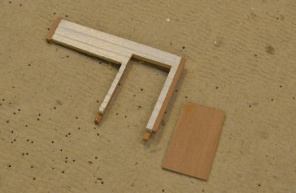
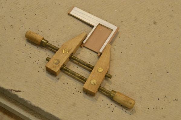
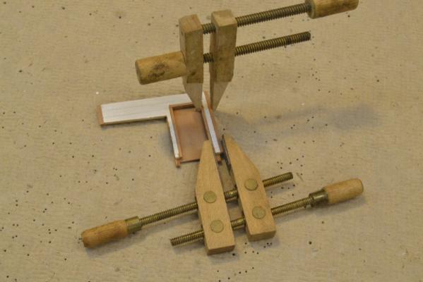
Young America - extreme clipper 1853 Part 124 – Skylights There were two glazed skylights on the poop deck that provided light and sometimes ventilation to the cabin deck below. The two completed skylights are shown below. The frames for the lights were made of interlocking parts with lap joints cut on the milling machine using a 1/32” bit in the setup shown below. Slots were milled to one-half depth in a 3” thick pear blank, then sliced to size with a thin slotting saw blade on the Preac saw as shown below. Slots for one long side/mullion and two short sides/mullions were milled into the blank. The next two pictures show the frame assembly. My shaky hands required the parts to be held in place for this work. I used sticky side up masking tape for this as shown. The next picture shows the finished frame before final overall sizing and sanding. The paneled walls for the skylights were made by the same method used for the companions, then painted white and fitted with natural wood corner posts. Both frames and a ridge rafter have been positioned on the aft skylight enclosure in the next picture. In the last picture the frames have been glued to the enclosure and protective brass wire bars and wire hinges added. After dropping this last frame into the cabin deck and fishing it out twice, I added the masking tape. This forward skylight was constructed with one side open, held up by two small wood supports. In this picture the after skylight has had beeswax/turpentine finish applied. Ed


- 3,618 replies
-
- 30
-
-
- young america
- clipper
- (and 1 more)
-
Hello Hakan. Thanks for your thoughts. Yes, it was a bit difficult to cut into those rails. I wished I had made the decision on this earlier. The pin rails were actually more of a problem and required drilling some new holes. I am just now working on the rigging plans and the belaying points and still do not have all of the final positions defined. Ed
- 3,618 replies
-
- 4
-
-
- young america
- clipper
- (and 1 more)
-
Hello John, Thanks for your question. In most of the work shown in the last few posts the pins are used against the parts and not through them. For the planks on the POB model the pin clamps are placed against the planks. However, I do use pins through pieces - especially planking on framed members. Holes are always predrilled. This requires some careful selection of pins and drills. The fit needs to be tight enough to hold the piece down but not tight enough to split it. This requires some pretesting. I push pins in and extract them with needle-nosed pliers. In pulling them out I apply finger pressure right next to the pin to avoid pulling the pieces apart or damaging the work. This is essential and works quite well. I usually place pin holes where fastenings - bolts or treenails - will be inserted later. Ed
- 191 replies
-
- 6
-
-
- young america
- clipper
- (and 1 more)
-
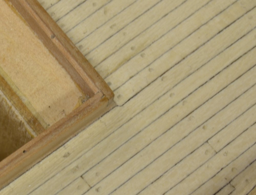
Thank you, Frank, and others for the "likes." Rob, to make simulated caulked deck planks I start with a wood blank about 45' long. the thickness of the plank width (usually 6-7") , and about 2"(actual) wide. One side is then painted with dark brown acrylic paints. More coats yields thicker caulk lines. A paper covering can be used instead of paint for a wider line. Individual planks are then ripped off the blank at the thickness of the planks (usually 3 1/2" for decks planks. I believe there are some pictures of this in earlier posts - perhaps in Naiad, and the method is covered in detail in YA Vol 1 and Naiad Vol II. Ed
- 191 replies
-
- 6
-
-
- young america
- clipper
- (and 1 more)
-
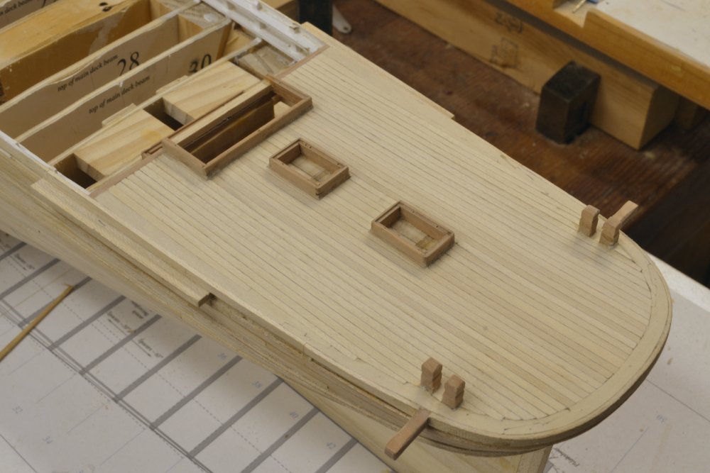
Young America 1853 – POB 1:96 Part 32 – Waterways, Binding Strakes, Margin Planks Before deck planking could be extended out to the sides, the waterways, binding strakes and margin planks needed to be installed. I worked on all these things concurrently – partly to break the monotony of deck planking and also to fill the time it took glued planks to dry. The first picture shows the blue waterway is installed on the starboard side. Installation of these members on the POB version is identical to the installation on the framed model and is covered in detail in the book and to a lesser extent on the 1:72 blog. The next picture shows the binding strakes being installed. I made these structural members with Castello to distinguish them from the ordinary holly deck plank. These members are also joined at the ends with hook scarphs. The next picture shows these members and some of the holly margin planking installed at the bow. Deck planking at the bow has begun in this picture. Planks have been notched as necessary to fit around the installed Samson post. In the next picture a barrette file is being used to clean up the inside edge of the margin plank on the port side. The next picture shows all three members installed on both sides of the forward hull. After the planks were installed, they were cut out to allow room for the bowsprit to fit against the forward bulkhead below the deck, Installing the planks then cutting the opening ensures that the strakes will be aligned. Of course all this forward planking will be covered by the forecastle. The next picture shows the decking approaching the margin planks at the side. Each plank is cut into the margin plank at one-half of its width. The planks were tapered back to the point of the next cutting. This process will be covered in the next part. In the last picture the planking is being levelled out with a flat riffler prior to sanding. The straight, parallel strakes of decking were continued outward until the gaps at the margin plank were completely closed. This final fitting will be covered in part 33. Ed


- 191 replies
-
- 29
-
-
- young america
- clipper
- (and 1 more)
-
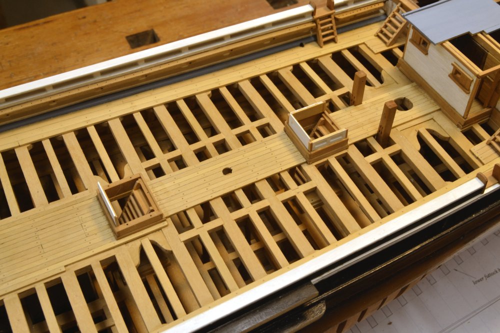
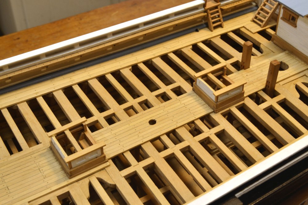
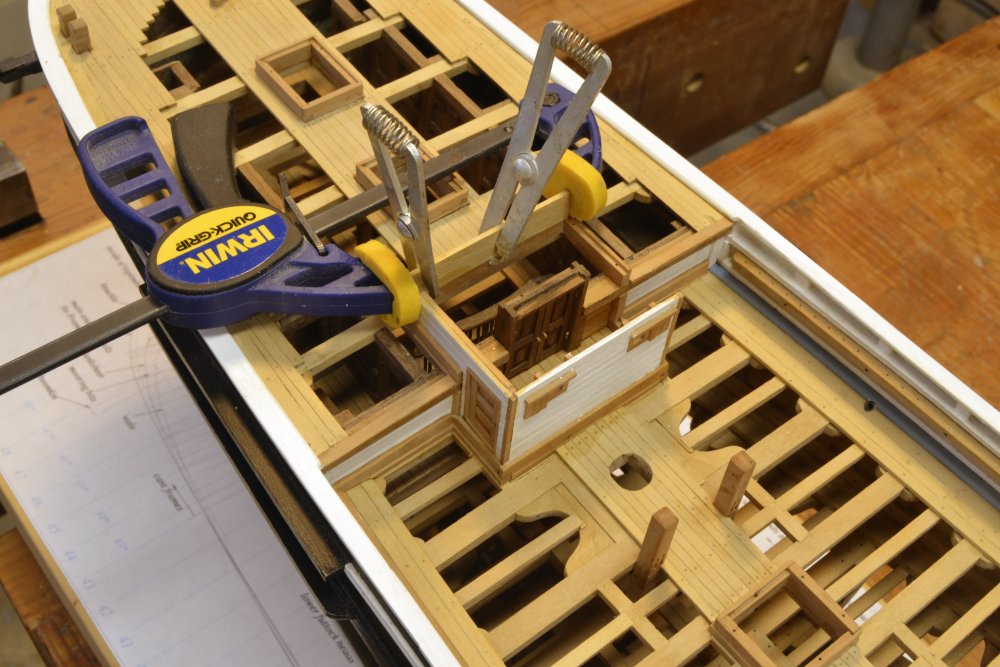
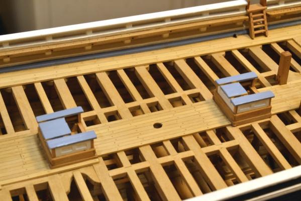
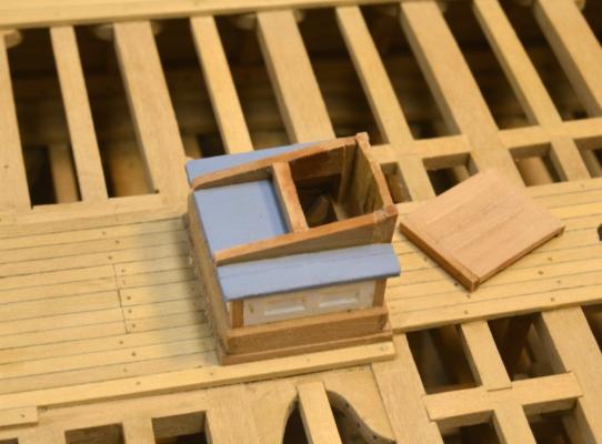
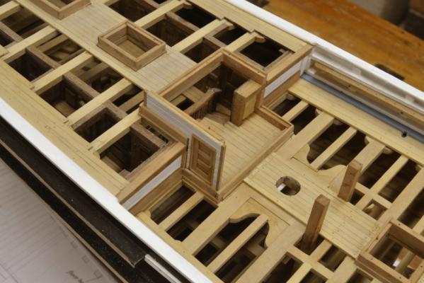
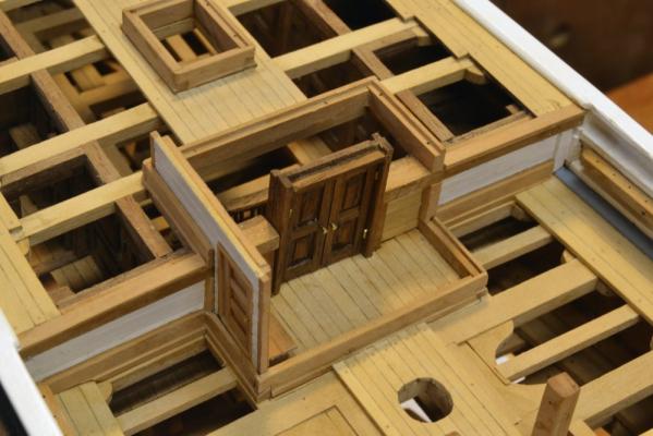
Young America - extreme clipper 1853 Part 123 – Companions Once the three ladderways into the lower decks were installed, the companion structures over these three hatchways could be constructed. Before describing construction the completed two aft of the main mast are shown in the first picture. All three structures are similar, with entry doors and a sliding panel to close them off when not in use. They are fairly intricate structures. In the one to the left in the picture the doors and sliding cap have been left open. Unfinished wood on these has been finished with beeswax/turpentine. The first step in making these is shown in the next picture. The side and forward walls are paneled. The first step in making the paneling was to trim long pieces with thin horizontal strips. The total thickness of these laminates is about 2 ½” (.035” act.). These pieces were then cut to fit the coamings and trimmed out as shown below. In the next picture one of these is being fitted into the rabbet on one of the head ledges. When the three sides were trimmed to size, they were painted white, fitted with natural wood corner posts and installed on the coamings as shown below. Additional internal members and the outer roof planks were then added as shown in the next picture. Next, the remaining roof planks, excluding the slide rails, were installed and painted blue. The rails, door jambs, door and a closing cross piece were then added as shown below. One of the sliding caps that were made to fit over the rails is shown in the picture. The last picture shows the companion over the forward hatch. The double-door entry to each of these was fitted with very simple brass wire hardware. Next will be the two skylights on the poop deck. Ed

- 3,618 replies
-
- 40
-
-
- young america
- clipper
- (and 1 more)
-
Dave, sorry I missed your comment. I have a similar array of life size machinery that I have been using on a regular basis for the last 40 years or so. Like you, I too have most respect for the router. There are no small router injuries. However, I feel safer with the table mounted router than with the handheld, especially the 2HP plunge router that I use for making deep mortises - even with a very elaborate and strong jig to confine the movement. Its something about the high speed router bit not being stationary. Same goes for the moving blade on the chop saw or a radial arm saw. I would not own the latter. Wood turning with gouges also has its moments of risk. Model shipbuilding remains a fairly safe pursuit. Ed
- 3,618 replies
-
- 6
-
-
- young america
- clipper
- (and 1 more)
-
Again, thanks for these comments. It is hard to ignore good advice. Since I expend a lot of ink describing processes I am of course very sensitive to all this. I have viewed this process as a micro version of using a radial arm saw to cut a dado - from above with the blade coming forward. In this case the cut is .028" wide and .028" deep - very small and at high tip speed, very low stress at the cut in wood. Under heavier duty one might well consider this a very flimsy setup. The main advantage of this method is a wide range of saw thickness/cut widths and thus precise sizing- in this case 2". A second advantage over making a special saw jig is setup time/expediency. The first advantage is somewhat important, the second less so. Like, Micheal, I too thought less about the exposed blade than the clamping, since no part of me ever got closer than 6" to the blade. The steel spring clamps were actually very tight, especially considering the low stress, but screw clamps would be better. Obviously, the preferred method would be to use an end mill. This is as fast but sizes of cut are limited. My smallest end mill is 1/32"(.03125"). The next step down that I have seen in the less-than-$100 price range is 1/64" - too small. In retrospect, a 1/32" tread thickness (2.3") would be a very acceptable compromise, and I admit would be the preferred method. I will soon have another opportunity to recover my good reputation for safety when I make the skylight windows. Thanks again for this input. Ed
- 3,618 replies
-
- 16
-
-
- young america
- clipper
- (and 1 more)
-
I thank you all for the concerns for my safety in the presence of the open 4" diameter blade. A couple weeks ago, I felt a similar concern for a guy getting set up to rip open a 3 foot diameter log with an unguarded 72" diameter blade. If a tool scared the daylights out of me I wouldn't for a minute consider using it. Ed.
- 3,618 replies
-
- 6
-
-
- young america
- clipper
- (and 1 more)
-
Jan, I will describe the method of simulating fastenings in the deck planking of this model in a later post. The decks on these ships were not treenailed, but iron spiked and capped over with wood plugs. Rather than describe the method here, I will cover in one of the next posts with pictures. Ed
- 191 replies
-
- 8
-
-
- young america
- clipper
- (and 1 more)
-
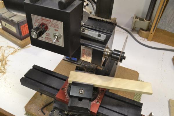
Thank you, Frank. I enjoyed meeting you as well. On the mill, one picture may be worth a thousand words, so I have attached one of the setup below. The mill is a Sherline 5400 Series fitted with one 1.2" spacer block between the column and the head. The head is rotated 90 degrees. The milling vise holds a "quick and dirty" wood "milling table". The vise is mounted on a graduated rotating base as shown. Ed
- 3,618 replies
-
- 10
-
-
- young america
- clipper
- (and 1 more)
-
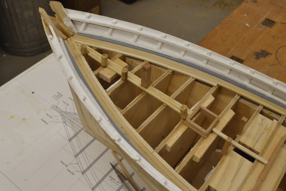
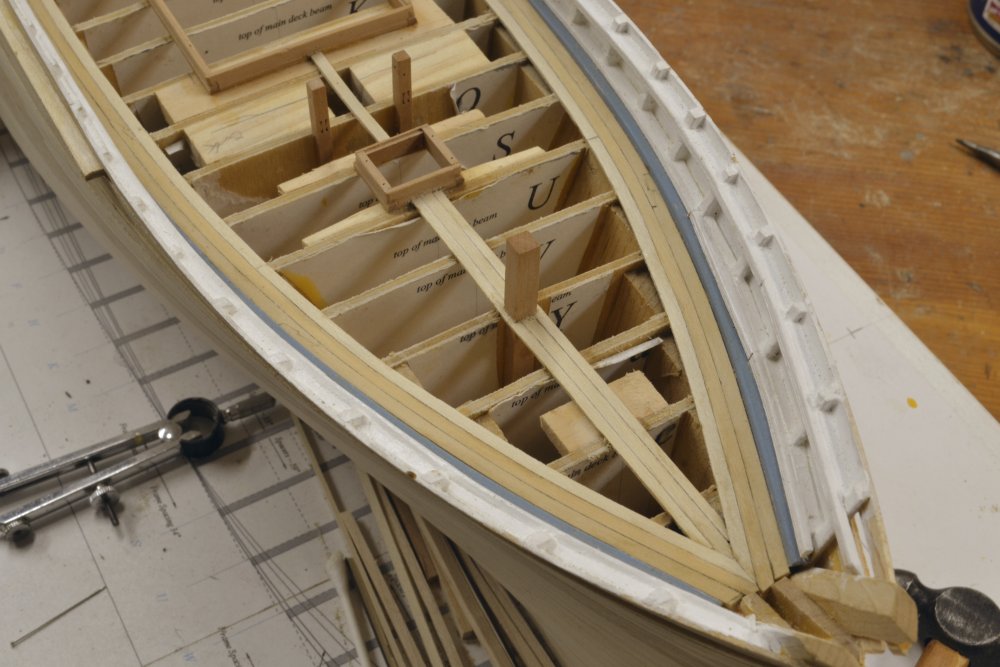
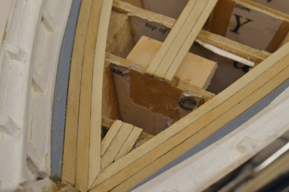
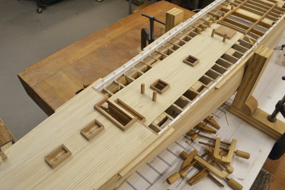
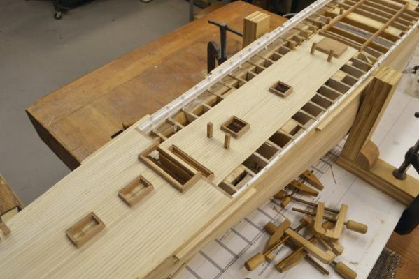
Young America 1853 – POB 1:96 Part 31 – Decking Readers may note that I am going into some detail on methods in this log. As I mentioned earlier, I wanted these posts to be a supplement to the POB model work described in Volume I of the book. Once the POB model is framed, common methods are used on both versions, but space did not permit pictorial presentation of both versions. So this should be helpful for POB modelers who are using the book. There are also a few twists on this version that may be useful. With all the hatchway and cabin coamings installed, the planking of the weather decks began - working from the central plank outwards with the strakes parallel to the centerline. Inside the waterways that abut the frames at the side, there are three strakes that follow the curve of the side on the main deck – two thicker structural “binding strakes” and one wide ”margin plank”. The margin plank is similar to that shown below on the poop deck where there are no binding strakes or waterways. In the picture the starboard margin plank is being glued to the tops of the frames and to the top outboard plank. These margin strakes were made wide enough to “cut in” the ends of the straight planks to avoid feathered-edge tapers that could not be caulked. The picture also shows the pin clamps that I used to hold all of the deck planking in place on this model. On the larger, framed version, planks were held down with pins pushed through tight holes drilled in each plank – into the members below. I did not wish to drill holes in this version, so used “pin clamps” that could be hammered into the plywood bulkheads at the edge of the plank being glued. I made about a dozen of these by drilling holes through small segments of dowel that would allow a tight sliding fit for ½” long lil pins, allowing the pin point to project from the end by about 1/8”. The pins were then glued into the dowels using medium viscosity CA. Pins can thus be driven by tapping the head of the pin with a hammer, and removed by pulling on the dowel with pliers. There is little stress on the CA joint in either case. These were very useful to say the least. The next picture shows the completed poop deck. As areas of planking were installed, the tops were leveled out using curved flat rifflers followed by sandpaper. The planks were initially cut about 1” thicker to allow for this. As described in Volume I of the book and in earlier posts, the planking material was painted on one side with dark brown acrylic paint before ripping the planks – to simulate caulked joints. Cutting planks into the margin plank is also described there and in other posts. The next picture shows the first central plank on the main deck being installed between hatchway head ledges. Accurate centering of these first planks is important. Although the hatchways were carefully centered on the bulkhead pattern centerlines, I marked a center on each head ledge by measuring in from the outsides of the hatchway with dividers. This helped ensure that the planking will be symmetric on each side of the hatch framing. If hatches are found to be slightly out of line as the planking progresses forward using this method, they may have to be moved slightly. In the next picture a plank is being marked for notching to fit around one of the mizzen bitts. Planks will most likely need to be notched to fit around the sides of hatchways. Where very thin widths would result, wider sections in planks along the side of the hatch were used, cut back to normal width to fit against angled cuts in planks at the ends. (I will look for a picture and post later.) Dark glue was used for all this planking. In the next picture a screw clamp is being used to close a joint at the corner of a hatch. The next picture shows the main deck planking progressing forward. To ensure adequate and symmetrical spacing between plank butts, I used a standard plank length that would span eight bulkheads, 7 spaces. Planks were thus about 35-40 feet long. This resulted in uniform and adequate spacing of butts both across and along the strakes. Planks on these ships were narrow – about 6”. On this model I used a standard width of 7” including the caulk paint. You will notice that the outer members – waterways, binding strakes and margin plank are not yet installed in the last picture. This work will be described in the next part. Ed Later: Here is a picture illustrating the planking configuration described above.

- 191 replies
-
- 25
-
-
- young america
- clipper
- (and 1 more)
-
Thanks for the comment druxey and to those who "liked" the post. The 9" tread height equates to .125" (1/8"coincidentally) in real measure, slightly more than the 8" standard height in most of our stairways today. Ed
- 3,618 replies
-
- 4
-
-
- young america
- clipper
- (and 1 more)
-
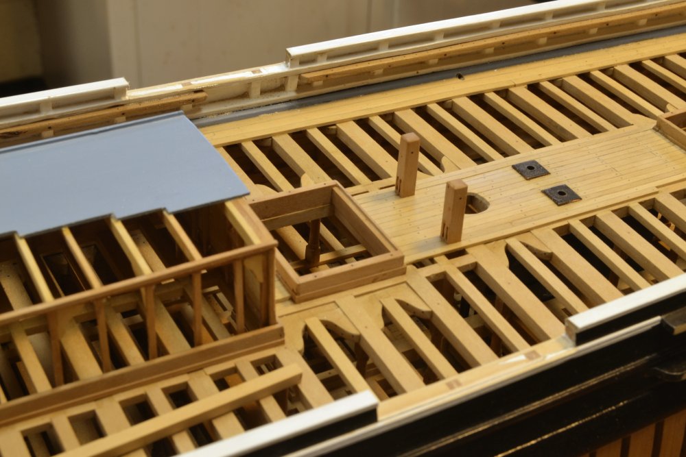
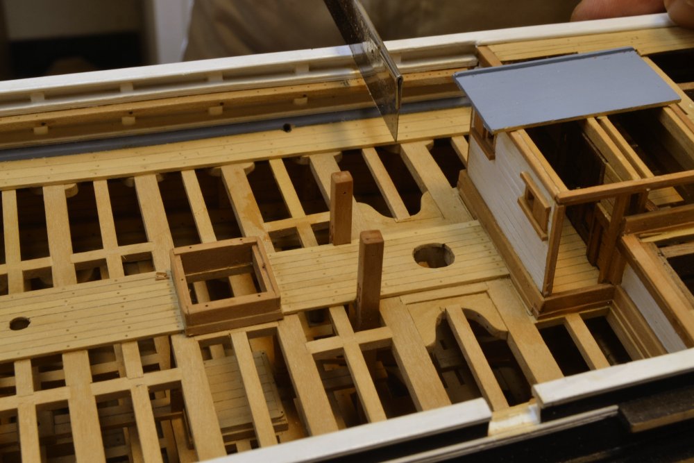
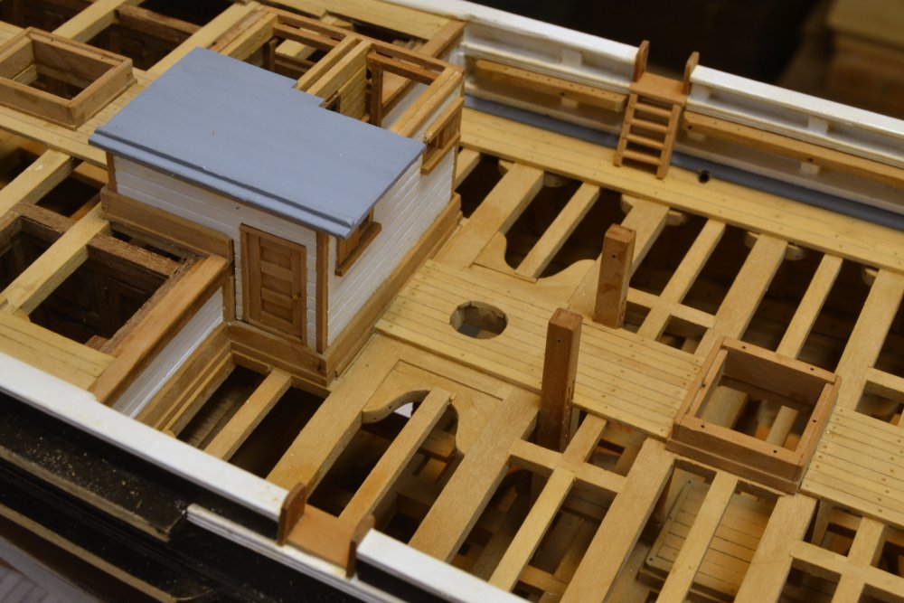
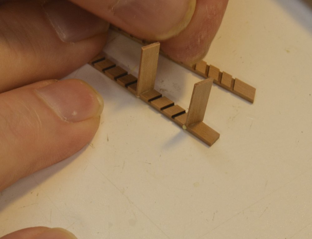
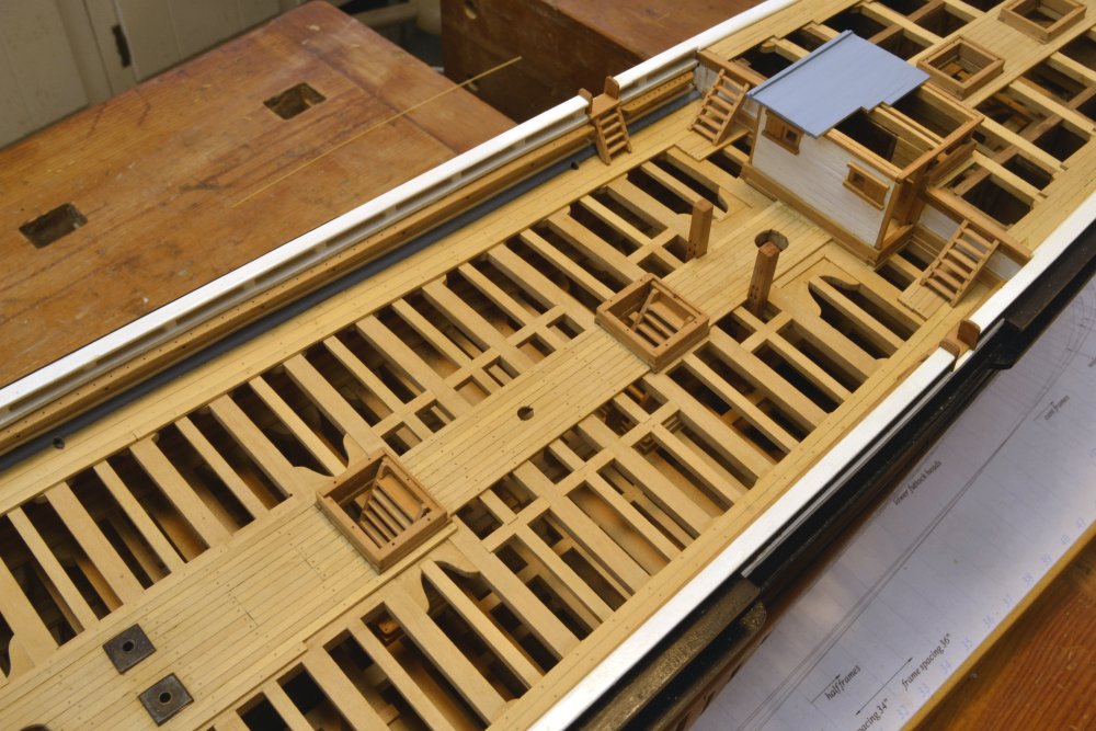
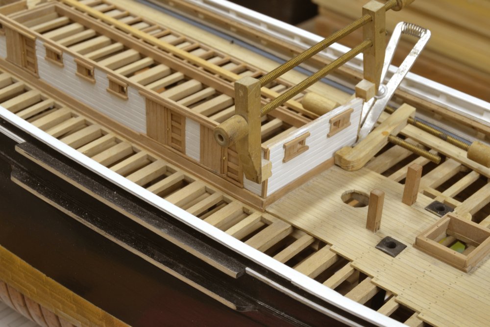
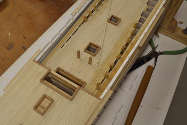
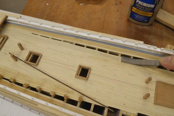
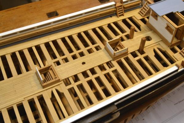
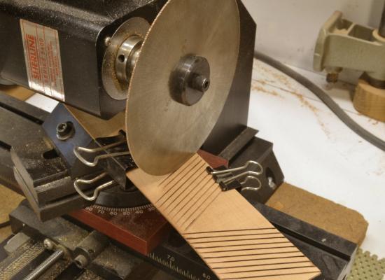
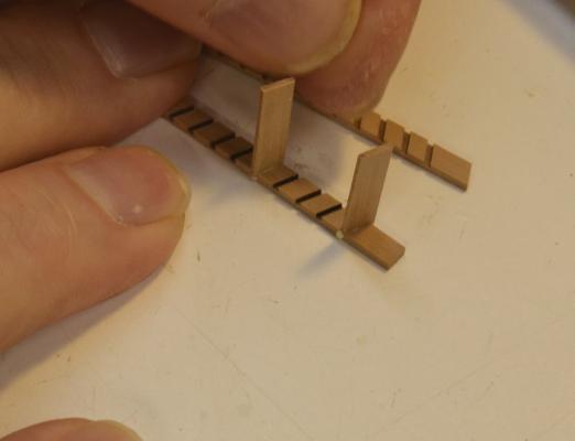
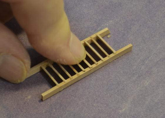
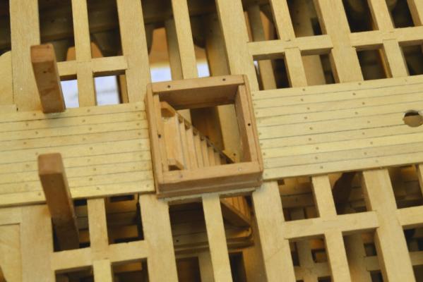
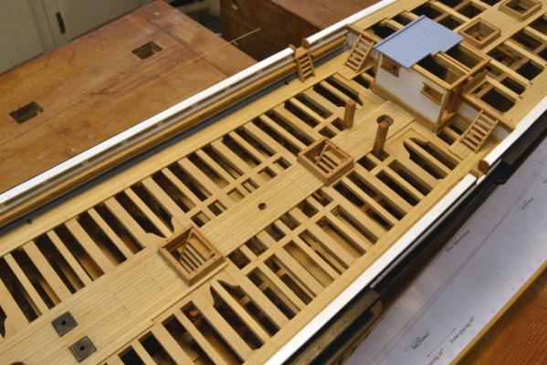
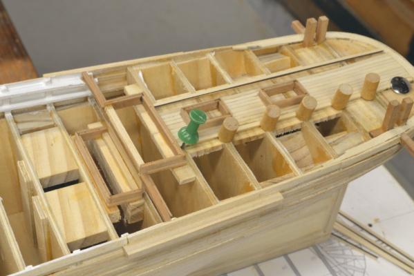
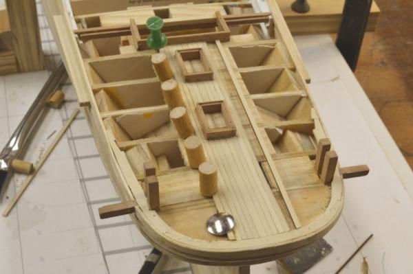
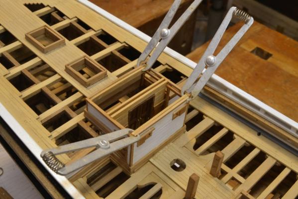
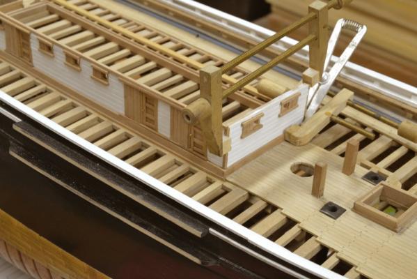
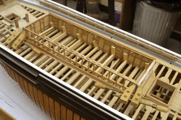
Young America - extreme clipper 1853 Part 122 – Ladderways With the two larger deck cabins constructed, it was time to turn to the several smaller deck structures. These include three companionways, two skylights, two small lockers at the forecastle break and the paneled housing for the rudder mechanism. I thought this work would be the next logical step, before moving on to the several fife rails and the machinery – the windlass, bilge pump, capstans and wheel. In preparation for making and placing ladders and stairs – work that must be done before constructing the companion structures – I had to finally decide the time period to base the model on. Young America had a long life – 30 years. Changes were made. I had tentatively decided to aim for the period after installation of the Howes double topsails (1854) and after pole masts were installed above the topmasts (1860’s?). Apart from my interest in these features, the two existing photographs of the ship were taken after these modifications. These photos are the best primary data source available and I spend a lot of time going over them with a magnifying glass. The photos clearly show two features that differ from the basis I initially used for the drawings and model. First, the entryway is shown well aft, adjacent to the mizzen mast. Also, there is a large area of each upper bulwark removed astride the main hatch. This was undoubtedly to facilitate loading and unloading cargo. The first picture shows the modification of the bulwarks to incorporate this feature. This change also required modifications to the pin rails to move belayed rigging clear of this area. The next picture shows me cutting the new entryway on the starboard side. The pin rails in this area were also cut out. The decision was now irrevocable, so I can stop thinking about it. The next picture shows the completed entryways. The method I use for stairs and ladders was fully described in Naiad, Vol II and to some extent in earlier posts. I use a milling machine to precisely set the angle, depth, and spacing of the treads on the stringers. The first picture shows this in progress. Mirror images of the cuts need to be made. The stringer material is 4” thick and the slots are cut 2” deep and 9” apart. The blade is about 2 ½” thick. I used a 4” (actual) diameter blade so the work will clear the underside of the motor. You can see by the shortness of the last two cuts that I ran into the column on the mill – but there was still enough material to make all of the 25 degree stairs. The ladders at the entryway were 15 degrees. This piece was then ripped into stringer pairs. The next picture shows a pair with treads being fitted. After installing the first two as shown, I fitted the other stringer and then slid in the remaining treads. The next picture shows the finished assembly being sanded to even out the treads. The next picture shows a stair assembly fitted into the aft main deck hatch. There are three of these companion hatchways. The last picture shows six of the nine ladder assemblies installed. There is also one into the forward hatch and two at the forecastle break. These last two were made but will not be installed until the windlass is in place. With this work done, the companionway enclsores can be constructed – next time. Ed


- 3,618 replies
-
- 35
-
-
- young america
- clipper
- (and 1 more)
-
HMS Naiad 1797 by albert - FINISHED - 1/48
EdT replied to albert's topic in - Build logs for subjects built 1751 - 1800
Oh my, that is some beautiful model work. Ed -
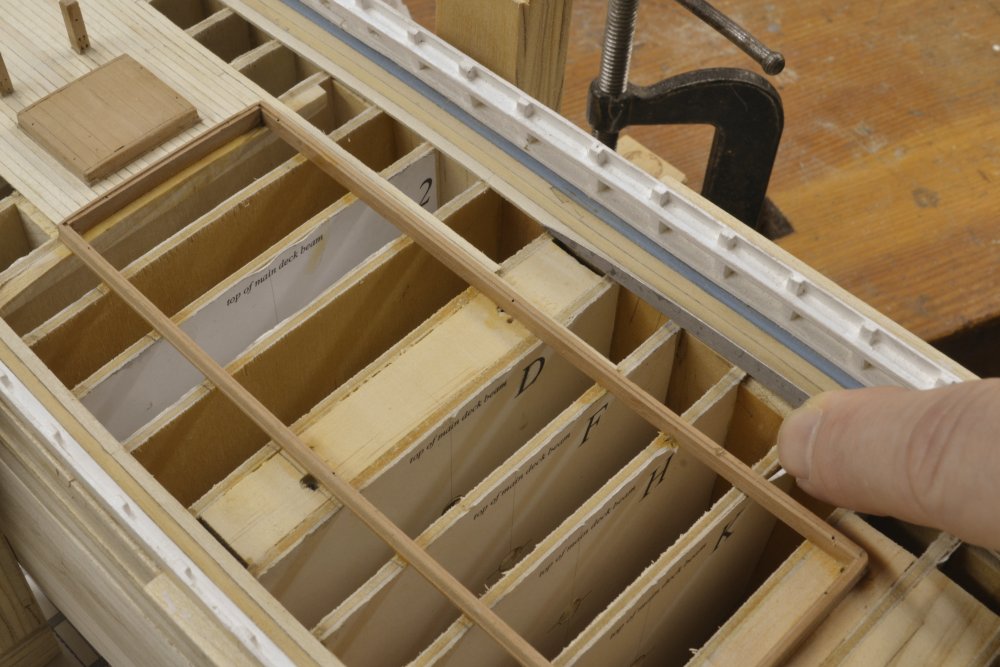
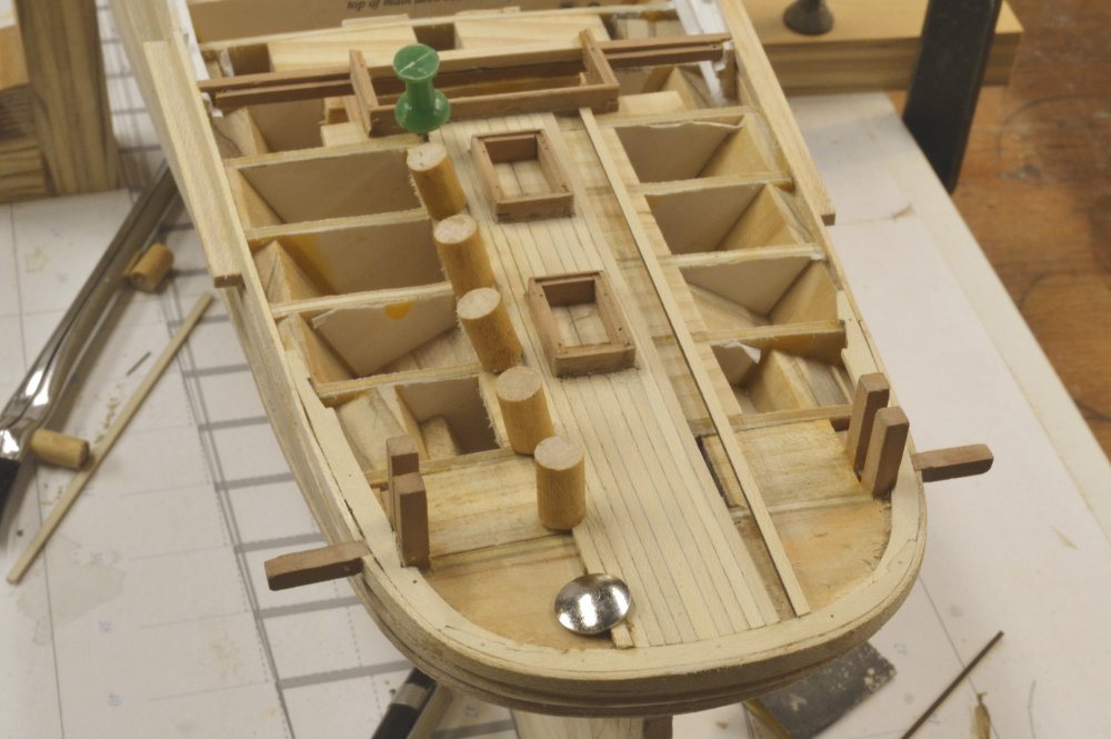
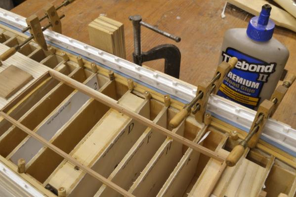
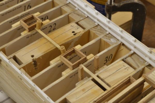
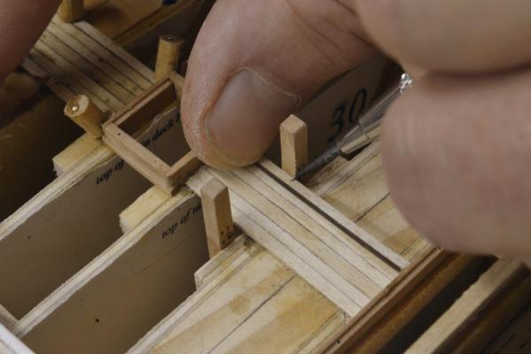
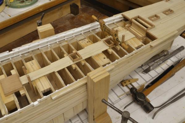
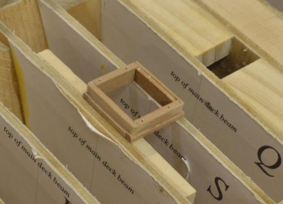
Young America 1853 – POB 1:96 Part 30 – Coamings I think I have mentioned before that the term “coamings” describes not only the entire hatch framing but also the fore and aft members. This can be confusing when writing – or reading - descriptions. The cross deck members are called head ledges. Coamings for hatchways and deck cabins needed to be installed on the model before decking could begin. On the full framed version, with its complete underdeck framing, the hatchways were built up on the actual opening. Since the POB model has only bulkheads at the stations, a template made from the deck plan drawings was used to assemble the hatchways. This is shown below. (Sorry, the main cabin template is mis-labelled "main hatch" on this early version of the template.) The hatchways for the POB model were made in exactly the same way as those on the larger framed model. I described this process in the build log for the other model and more thoroughly in the book. In the next picture a dovetailed lap joint at the corner of the main deck cabin coaming is being fitted. These corner joints are a bit complex, but as I said, they are well described elsewhere. In all cases the cross-deck head ledges fit over the ends of the coamings, thus clamping them down. Head ledges were bolted through the beams, while coamings were fitted over carlings that were normally only wedged between beams – thus having little resistance to upward forces. The excess stock at the corners was removed after assembly when the corners were squared off and the above deck parts rounded - by sanding/filing. The next picture shows the poop deck portion of the coach coaming being constructed. A reinforcing strut was glued into this assembly to maintain the correct width. The next picture shows a finished hatchway installed on a bulkhead and on to one of the supplementary pine members described in an earlier post. To support the ends of the planks forward of this framing, another supplementary member was need and later installed. In the next picture the coamings on the poop deck have been installed and planking has begun starting with the central plank. Note that the cap on the breast beam was cut out to fit the aft section of the coach framing. The lower part of this coaming is shown installed on the main deck. These two assemblies had to be carefully aligned so the side walls of the coach would fit neatly – and vertically. Another view of this is shown in the next picture. This picture shows the first version of the pin clamps I used to hold down the glued planks on this model. I will discuss the improved final version of these in the next part. Ed
- 191 replies
-
- 28
-
-
- young america
- clipper
- (and 1 more)
-
Thank you for your comments, Micheal. I decided to use the masking tape in this case because the fitting of the cabin rafters and small knees required use of tweezers and high risk of dropping parts into the lower hull where they can be very difficult to extract. This sometimes requires upending of the model - not something I like to do very often. After dropping a few pieces I resorted to the tape. I have tried paper cutouts with less success. I also used the tape to cover the open deck when painting the bulwarks. I did not detect any residue when removing it in either case. Because of expected work, I have not applied finish to the weather deck structures as yet. Ed
- 3,618 replies
-
- 3
-
-
- young america
- clipper
- (and 1 more)
-
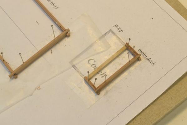
Young America - extreme clipper 1853 Part 121 – Coach The coach was really just a vestibule at the break of the poop to provide access from the main deck to the entrance of the “mezzanine” level cabin deck below. It is an interesting and intricate structure. Its forward end is just large enough to fit an entrance door on each side and that part is supported on a coaming on the main deck. The aft part merely provides headroom above the main deck level over the head of the staircase that leads down to the cabins. At the break of the poop is a double-door entrance to the head of the cabin deck staircase. As mentioned before, the design of all this interior work is speculative. The first step was to make and fit the starboard side panel on the coamings on both decks and to the bulkhead at the break of the poop. In the first picture that wall has been built up of planks in the usual way and then cut to fit. In the picture the forward corner post is being glued on. In the next picture the studs on the inside of the wall have been installed and the door opening cut out flush with those members using the circular saw for most of the cut length. A panel for the entrance door was then cut and fitted to reinforce this very fragile structure and provide a base for the door paneling. In the next picture the panel is being glued in. The outer door jambs and header are being added in the next picture. In the next picture the door has been paneled inside and out and the wall installed on the coamings. I made the doorway into the cabin itself a bit more ornate, using the same wood and trim style used in the cabins as shown in the next picture. In this picture the double doors have been fitted with simple brass hardware. As with the cabin woodwork, I used black walnut for the doorway. In the next picture the finished forward bulkhead is in place and aft bulkhead is being glued in. The wall on the port side consists only of the stud framing – to provide some visibility to the interior. In the next picture that framing has been installed and other work is in progress. In the picture the overhead rafters have been installed as well as the structure and panels on either side of the doorway. The exterior end trim pieces are being glued on in the picture. The last picture shows the freshly painted roof on the finished coach. This picture also shows a new entryway on the port bulwark and some modifications that I will explain in the next part. Ed


- 3,618 replies
-
- 38
-
-
- young america
- clipper
- (and 1 more)
-
Hello Marc, It was good to meet you at the conference and I am glad you will find the book useful. All the best, Ed
- 3,618 replies
-
- 4
-
-
- young america
- clipper
- (and 1 more)
-
Thank you, David. I use artist's acrylics, except on metal. Acrylic gouache (usually Jo Sonja tubes) and liquid acrylics ( usually Golden Fluid Acrylics). The gouache dries dead flat and the Golden has a gloss. Ed
- 3,618 replies
-
- 4
-
-
- young america
- clipper
- (and 1 more)
-
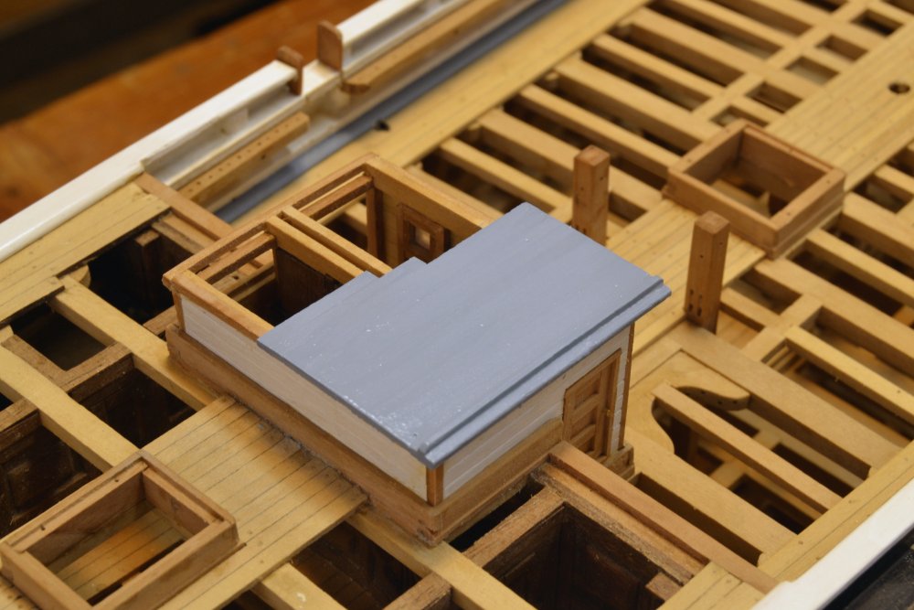
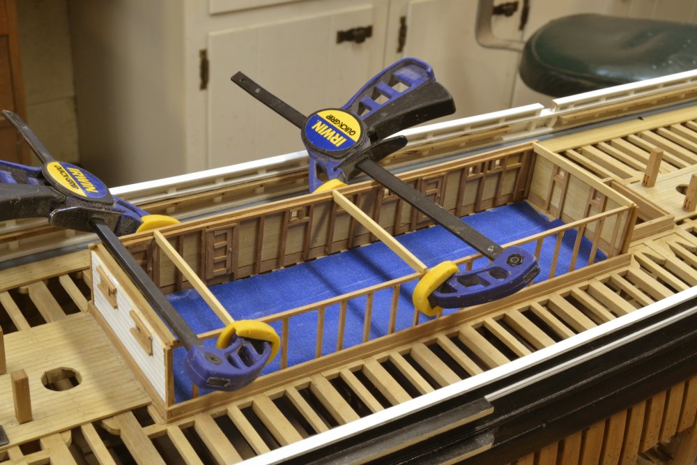
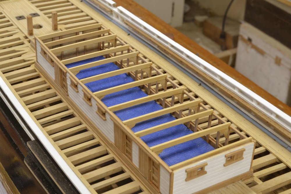
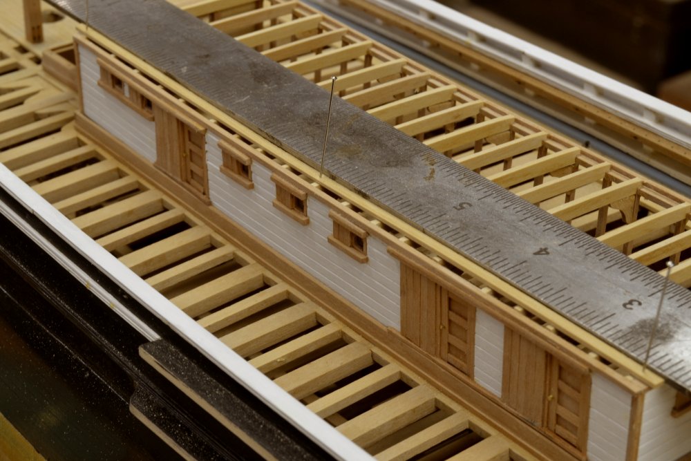
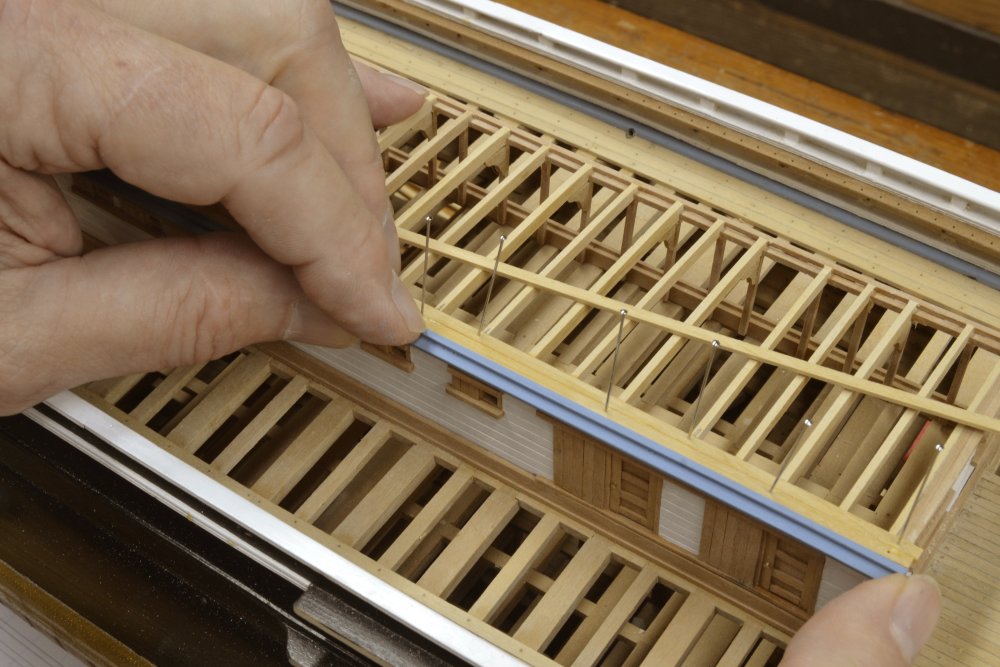
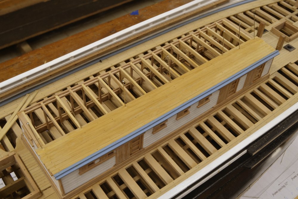
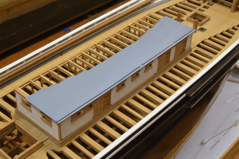
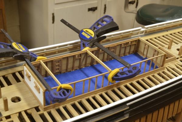
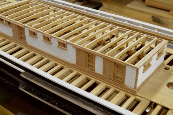
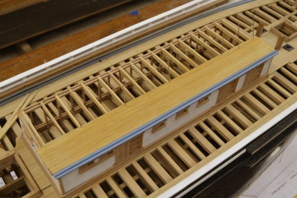
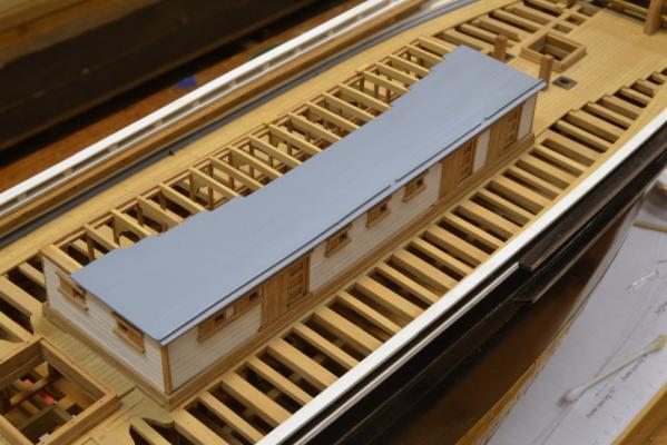
Young America - extreme clipper 1853 Part 120 – Main Deck Cabin 2 Work on the deck cabin continued. In the first picture the starboard side has been installed and the forward bulkhead is in the process. All the bulkheads were made to fit into the rabbet on the coaming. In the next picture, both end bulkheads are in place and the framing for the port side is being installed. Pine strips with wedges were used along the floor to hold the studs against the coaming at the bottom. The reinforcing pine batten is still pasted in place. This side of the structure will be left open for visibility into the framing below. In the next picture the pine batten has been removed and masking tape has been placed on the deck framing to prevent small pieces from dropping through. These can now be very difficult to extract. The first of the rounded up roof rafters are being fitted. In the next picture these have been installed. A number of them have been fitted with hanging knees to provide some wind bracing. This structure had to be quite strong. In the next picture the masking tape has been removed and the tops of the end bulkheads trimmed out in readiness for the roof planking. The next picture shows the initial strake of 3” x 7” roof planking being aligned against a straightedge and pinned in place. There is a strake with a water stop to be fitted outside of this one, but I wanted to paint that first and use the next inner strakes for alignment. The next picture shows that outer strake being fitted against the two initially installed planks. In the next picture the planking has progressed almost to the centerline. The last picture shows the finished roof. The ends of the planks have been sanded square and notches cut through the water stop for the two transverse skid beams that will cross the roof. The roof has been coated with acrylic sanding sealer, sanded smooth and painted with the same color blue as the waterways. The paint is acrylic. The next task is to construct the coach – the entrance to the cabin deck. Ed


- 3,618 replies
-
- 48
-
-
- young america
- clipper
- (and 1 more)
-
Gianpiero, Thanks for the 26 likes. It looks "like" you were catching up. Ed
- 3,618 replies
-
- 2
-
-
- young america
- clipper
- (and 1 more)