HOLIDAY DONATION DRIVE - SUPPORT MSW - DO YOUR PART TO KEEP THIS GREAT FORUM GOING! (Only 20 donations so far - C'mon guys!)
×


kruginmi
-
Posts
629 -
Joined
-
Last visited
Content Type
Profiles
Forums
Gallery
Events
Everything posted by kruginmi
-
 Great Job! It was a lot of fun watching this come together. Appreciate the pics and build notes. Mark
- 335 replies
-
- 2
-

-
- Constitution
- Mamoli
- (and 3 more)
-
Good job Mike, slow but steady..... Any finish you use should make that line pop also. Mark
- 968 replies
-
- 1
-
-
- hahn
- oliver cromwell
- (and 1 more)
-
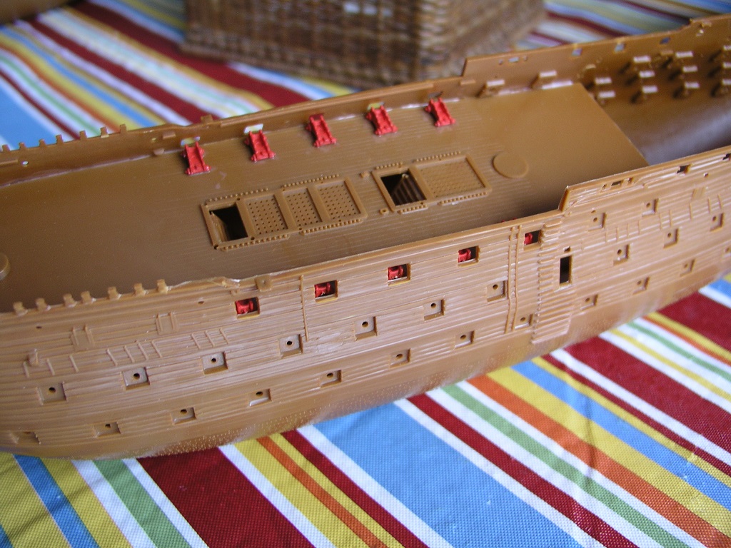
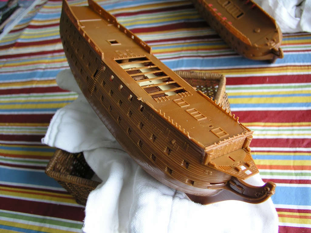
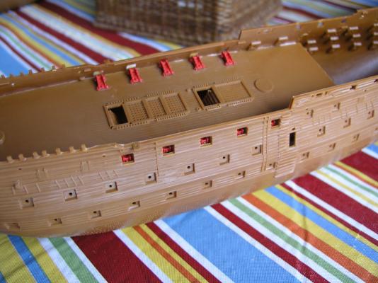
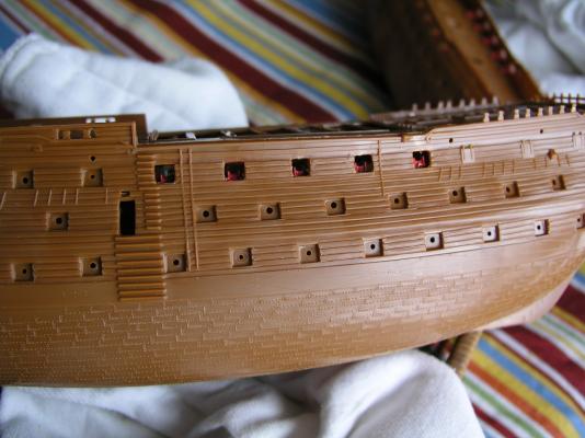
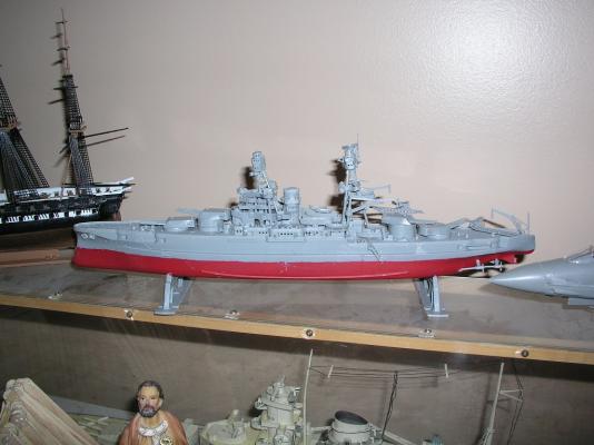
Getting my head back wrapped around plastic AND working with a younger kid. After gluing the lower deck in independently we painted then set the gun carriages in. Yes it would have been much easier to paint the deck prior BUT....effective gluing down of the carriages required plastic to plastic. The instructions show the carriages installed after the upper deck - who follows instructions? Now, Peter was able to put them in with his fingers. We had put some cannon barrels in previously to determine how far in the carriages should go (consistent with the dummy cannons). A little extra glue here and there but nothing paint (now) wouldn't cover up. I forged ahead a little with mine to show him what to do on his. After painting the gun deck satisfactorily I now installed the upper deck. A good squeeze to get in which mostly held it in place, with some help from some rubber bands. Trying to follow the instructions and get the two decks glued in concurrently with the hull halves would be quite the feat. With the process above everything is aligned and secure. Painting all looks good and everything proper. There are still two ships boats to host on the frames. Will I put the deck to deck posts in? Still considering. Relatively easy to do, just don't know if they are visible at all and worth the effort. Stay Building my Friends, Mark and Peter

-
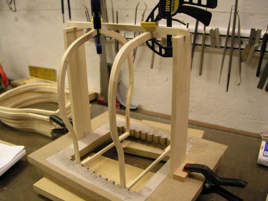
Slow but steady. I worked the inlays into the front frame using walnut - that should make them pop with the finish. After everything looked good I glued the frame to the jig. I have begun work with the 27th frame (opposite) to do the same. I waited until this time for these pieces so I could accurately account for the bevels. This is targeted for eye candy so I wanted the join pieces to be placed consistently to look their best. Lots of time spent on the frames. If you have a solid base that is correct, the rest of the build is sooooo much easier. Bummer most of this will not be seen/ The outside of the hull is now faired (the inside is not as is pretty clear). After doing the 27th frame my goal will be to get the wales on for maximum strength and then work the rabbet into the keel prior to attaching that. Stay Building my Friends, Mark
- 172 replies
-
- 10
-
-
- druid
- sloop of war
- (and 2 more)
-
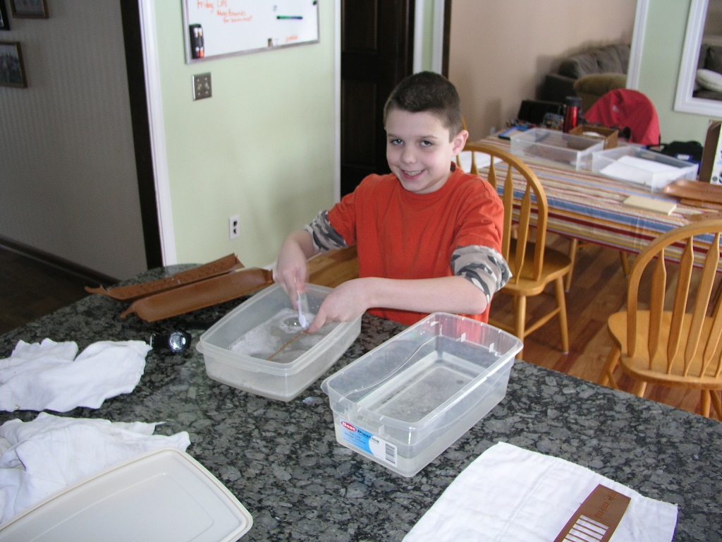
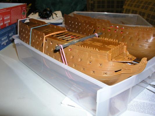
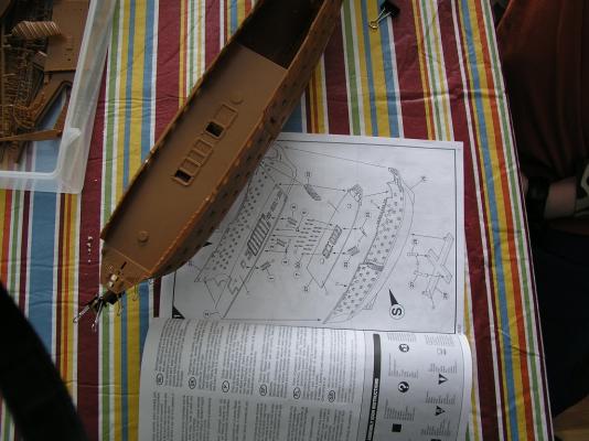
And we are off..... Peter has really learned not to just grab the glue bottle and get the model assembled in one or two days which really helps. First step was to wash the parts directed for use today, the main hull and decks. This model is not the easiest to position the two main decks into the hull halves (already talked about in a separate build log). Last night, knowing this, I did some practice assembly to figure out the best approach for us. Additionally, I wanted to provide the clearest guidance to Peter on where to paint and especially where not to (glue line for decks onto hull). I finally came up with a modified path that I think will work. The two hull halves are to be glued together by themselves (no decks). Tomorrow the lower deck will be glued in by itself to be followed a day or so later (after the lower deck is painted) by the upper deck. This seems to keep everything in control and accurate. In the pics I just put in the deck, the hull providing the grip to keep it in position. Peter can be let loose painting soon enough with not too much concern on my part. There are deck to deck beams near the middle of the lower deck. These are the only 'sticky wickets' as they say. I am not too worried about them. Now off to allow the four year old some painting on other crafts. Stay Building my Friends, Mark and Peter

-
Looks like a great build. Love the enthusiasm - keep having fun! Mark
-
Wow, I have never seen this kit before. Really interesting and nice job! You need to share with me how you have been able to do what you have done without snapping the bowsprit / jib boom. I am like 0 for 4 in that department (with much bigger scales). Mark
-
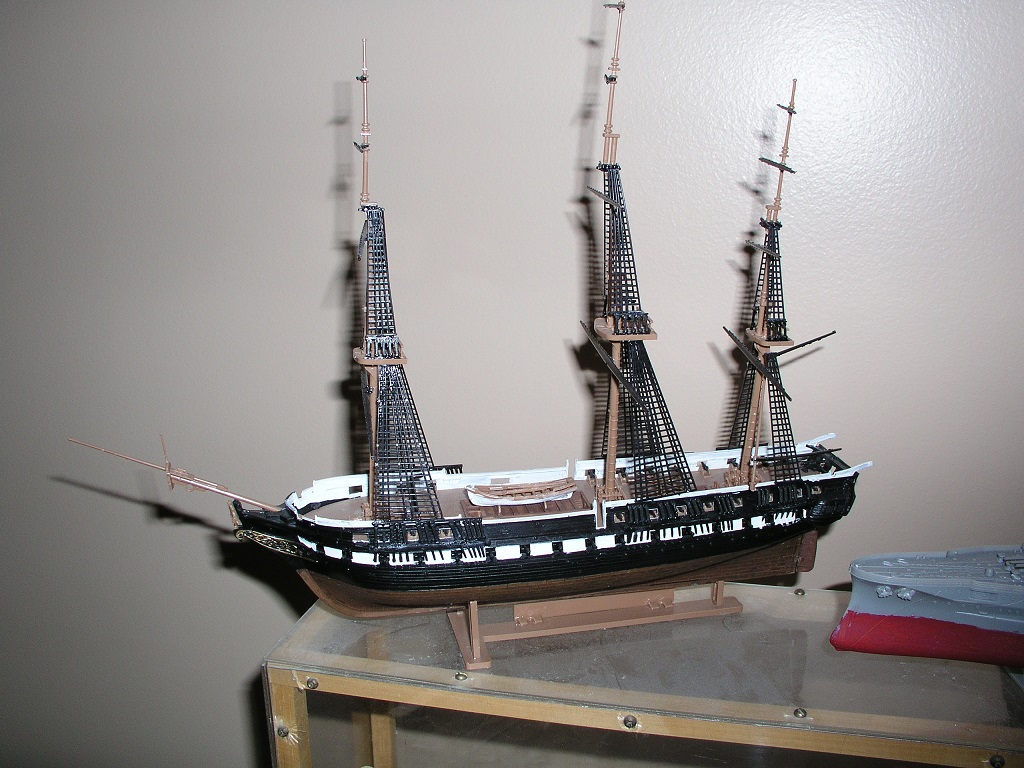
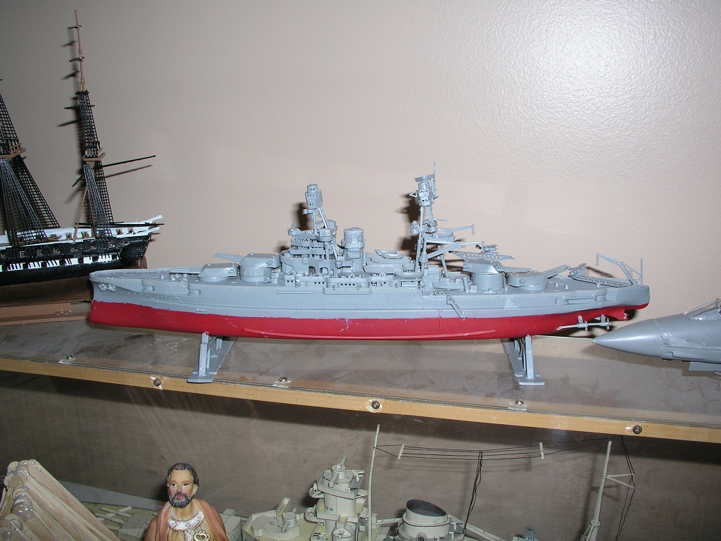
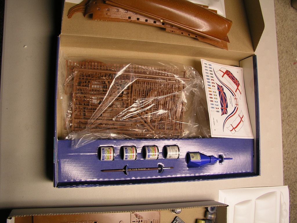
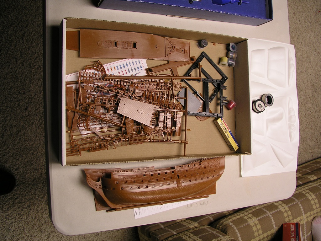
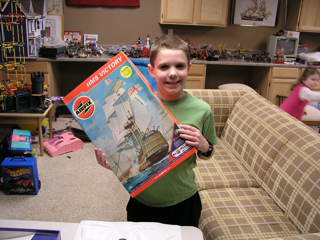
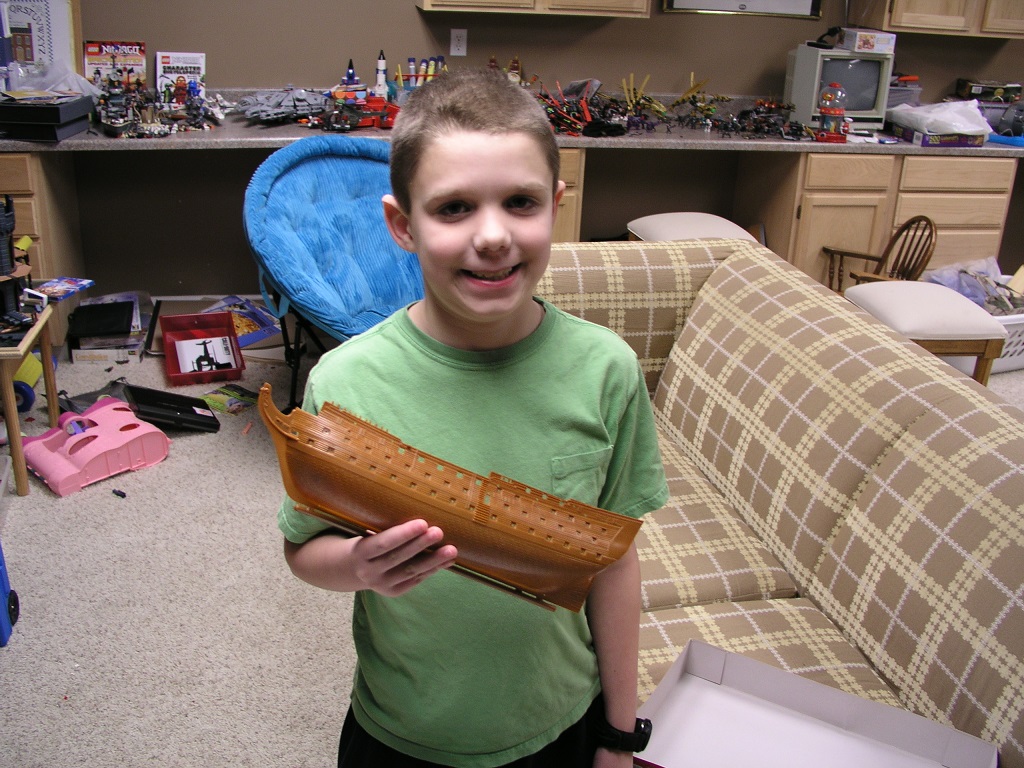
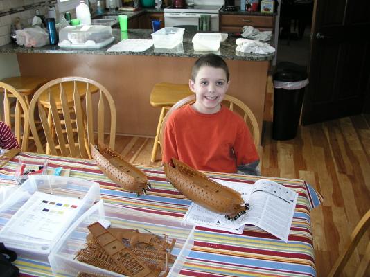
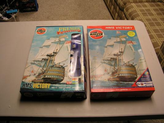
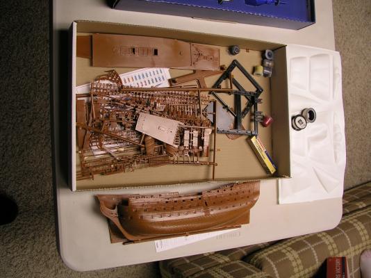
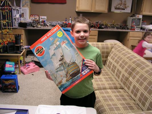
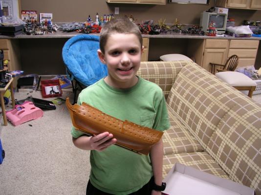
With my 9 year old son now having three models under his belt (two ships) with my help: He asked what was next on the horizon. I was actually given an Airfix 1:180 HMS Victory model recently and I realized I now had two in stock. So.....we are going to do dual builds. The models are packaged differently but contain exactly the same kit components. We are laying things out and mapping out our plan. I am planning to do this one out of the box with no 'improvements.' His model will be all him. It will be interesting to get back into painting. The paint in both boxes is quite old so I will buy new acrylics locally (as close as possible in color). He is the only kid so far (fifth of six) that has had any interest in models so I am doing whatever I can to fan the flames - how can you do wrong with the Victory? Looking forward to spending the time together, Mark


- 13 replies
-
- 10
-
-
Looking good. Kudos to trying and sharing. Mark
-
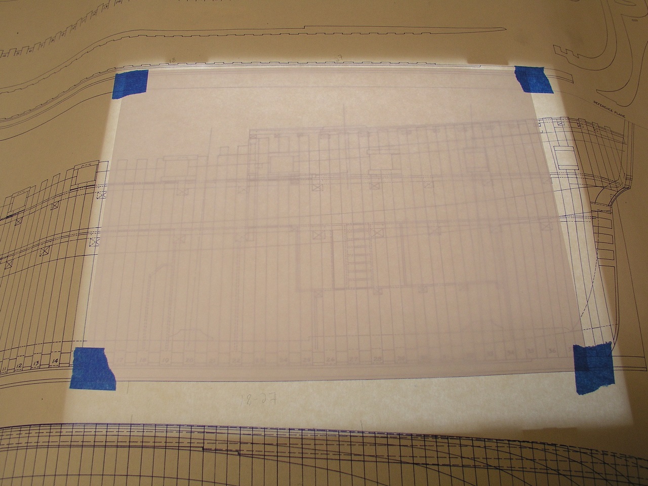
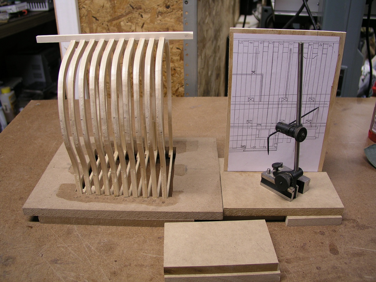
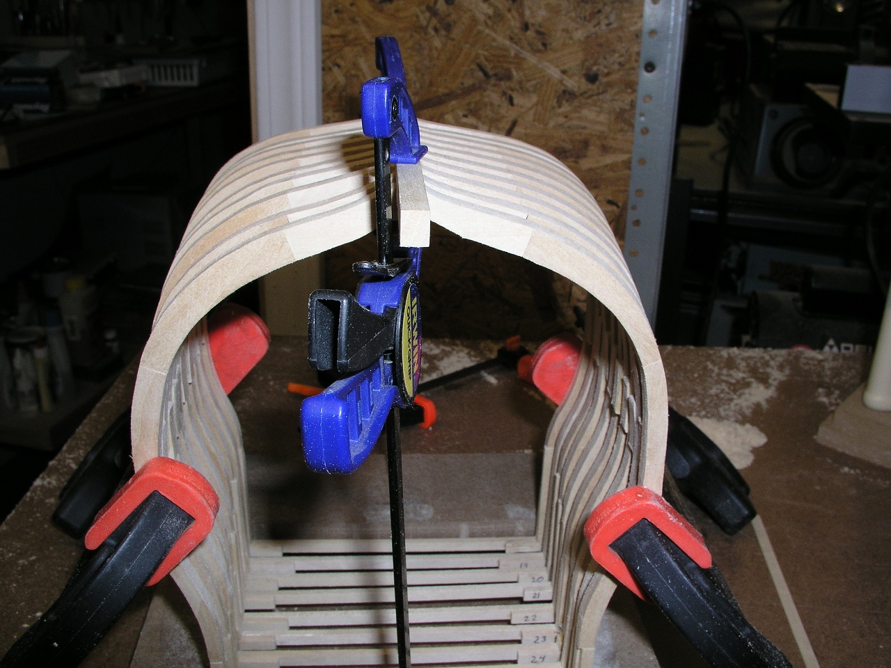
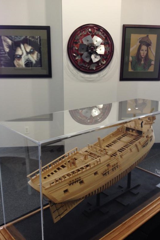
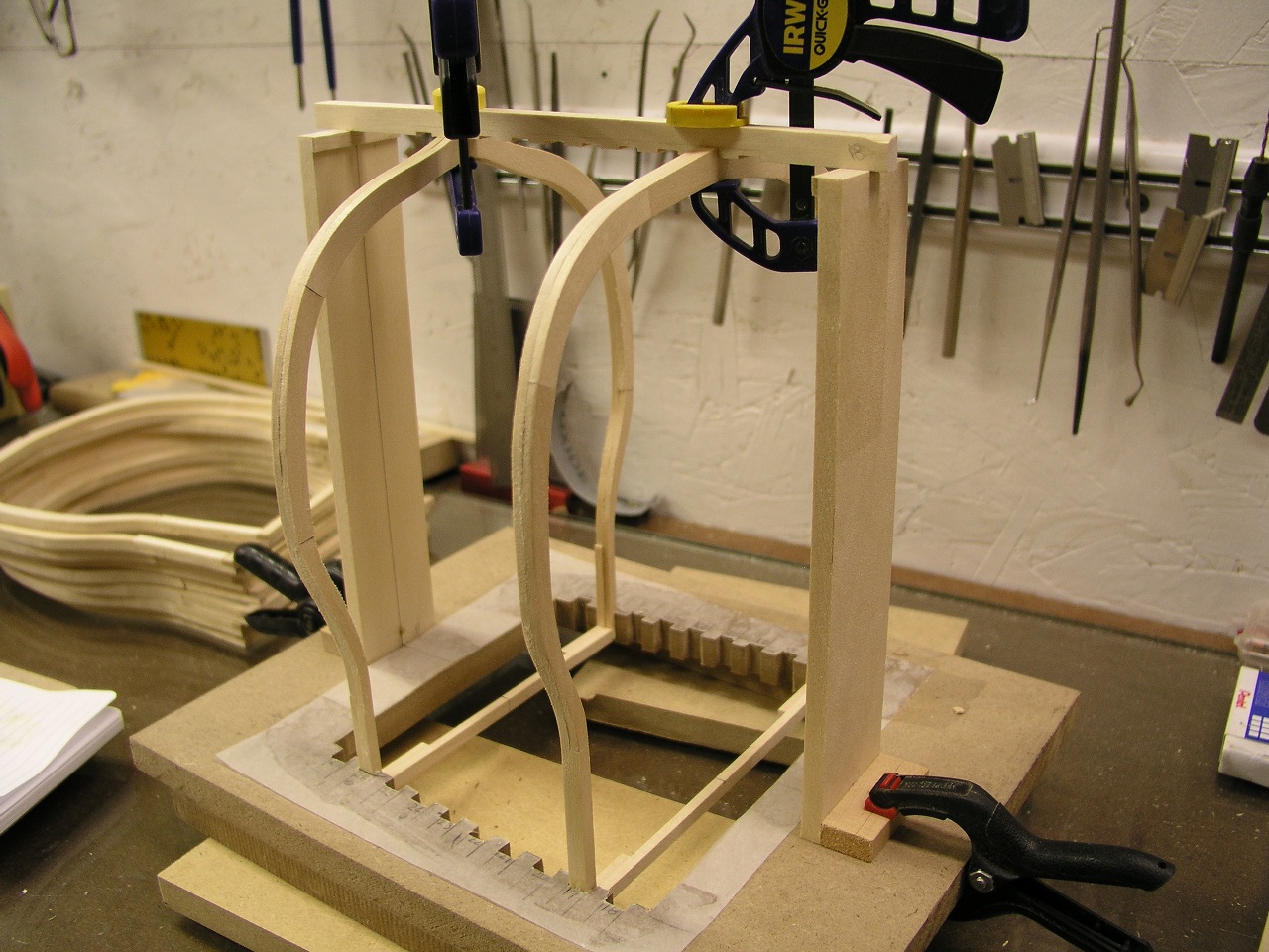
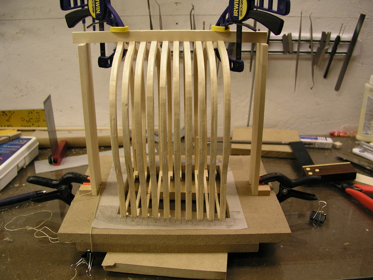
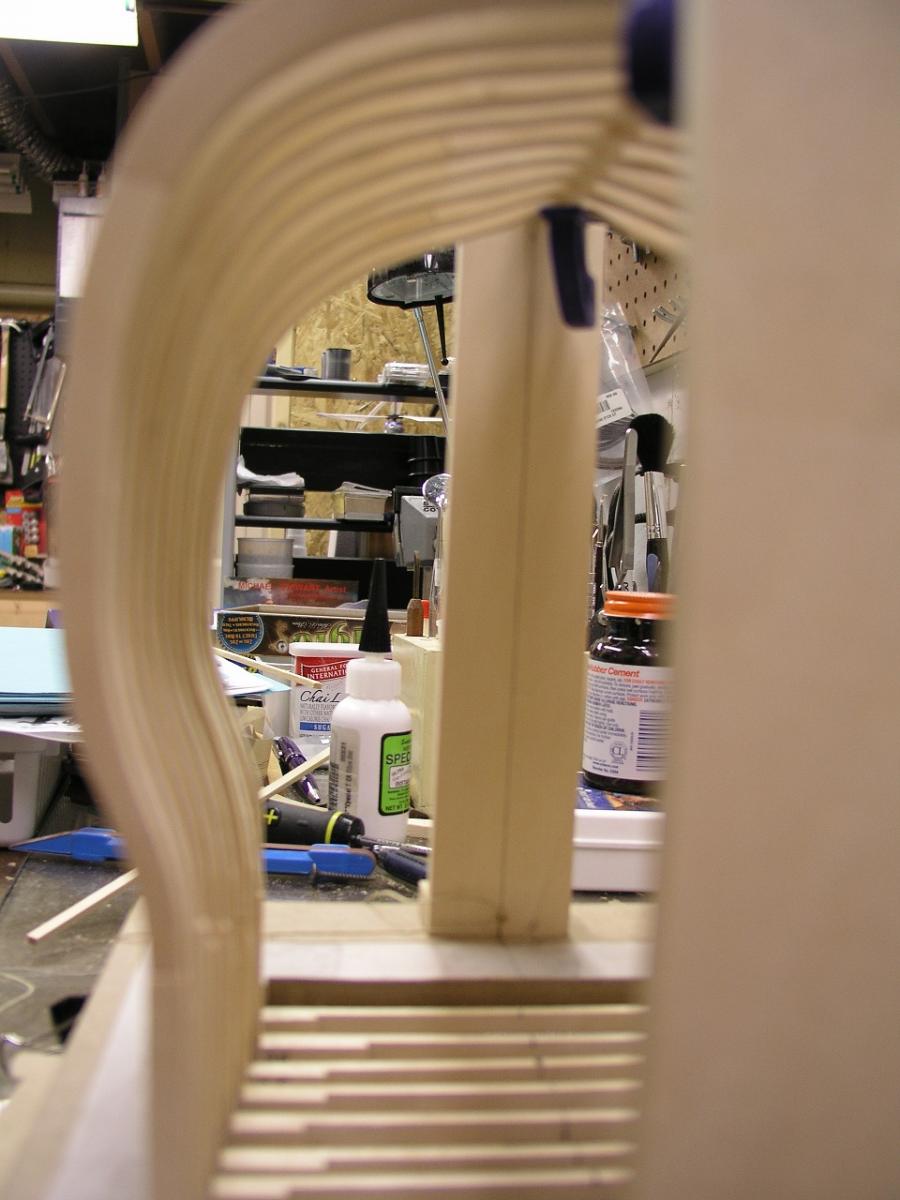
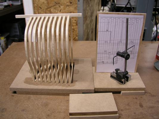
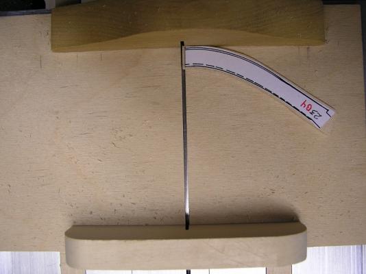
Now to put the bevels in. First step is to add spacers between the frames where the main wales will be. So....I need to know the height for each frame. I used a light box to copy the plans for the cross section to a blank piece of paper. I then cut the plans so the floor was equivalent to the base jig. This was then glued to a form that allows measurements to be taken off. . I then was able to take measurements of the wale upper and lower limits and transfer to the model. Then spacer pieces were added. THEN the sanding starts. I was just focusing on one of the external sides initially. When the full outside is done I will attach the wales for complete stiffness before attempting the inside. I did find the frames had some 'issues' conforming to a pre-bevel ready install. I had flashbacks to the original Druid when I had problems in the same area. I had though using the top spreaders would solve how this happened but I think there are a couple of issues with the drawn frames on the plans. I actually cut one of the lower legs and re-glued in a slightly different orientation to make things match up better. Some other frames had their slots enlarged to allow more movement prior to gluing. You go slow and check your progress often and it was slowly brought into alignment. I had a plank at the ready and checked how it laid on the hull often. As a note the first and last frame are still not glued in. I wanted to see exactly how the bevels affected them prior to adding the futtuck join pieces to insure they visually looked right. For a current look and comparison, the following shot shows a beveled hull on the right and untouched on the left - big difference. All this work will be hidden (except the keel) and it might thought to be overkill but I wanted this build to be equivalent to the original build. As an aside, I include a current view of my full HMS Druid at the Lowell Arts Building (pic from them). Not looking too shabby. Stay Building my Friends, Mark


- 172 replies
-
- 8
-
-
- druid
- sloop of war
- (and 2 more)
-
For a first build you are going to probably handle the ship a lot off of the clamp anyway. If everything can start straight (no warpage of the out of box base formers) the important thing is to alternate putting planks on from one side to the other to avoid inducing a warp. I have built a couple of ships with out any clamps. Not saying that is great or wrong. I really like to hold the hull in my lap as I figure out the run of the planks and while attaching them. As the replies show, a lot of people like reinforcing the bulkheads. For a smaller ship not super important (not counting the bow and stern where additional glue area always helps at the termination of the plank runs). The important thing is to forge ahead and get experience - and finish it! You will learn what works for you and what doesn't. Mark
-
Love the colors and how it makes everything pop. Great attention to detail. Mark
-
I live by the Airport. Looking forward to seeing this come to life!
- 42 replies
-
- 1
-
-
- Constitution
- Revell
- (and 1 more)
-
Good to get going Tom! Note: I have 2.5 kits of the same Constitution that have been given to me. If you need any extra parts come on over to Grand Rapids and I can get you supplied. Mark
- 42 replies
-
- 1
-
-
- Constitution
- Revell
- (and 1 more)
-
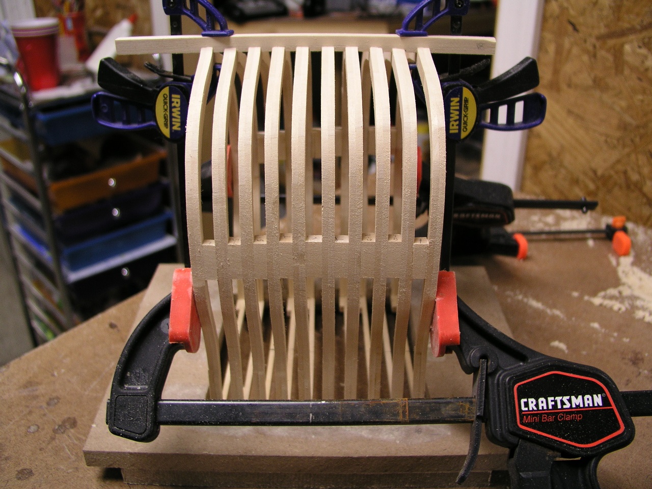
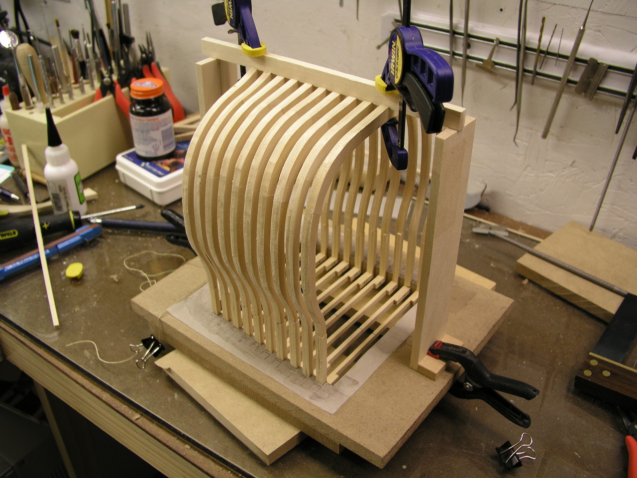
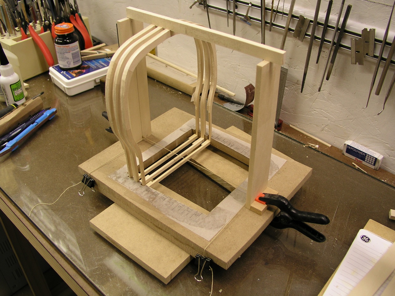
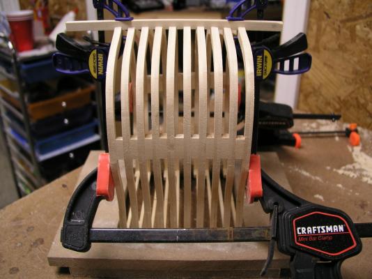
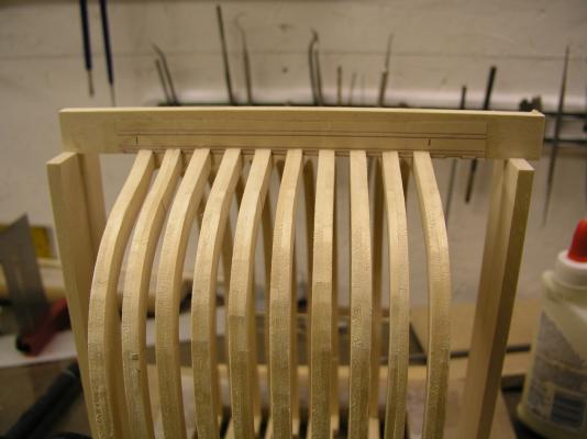
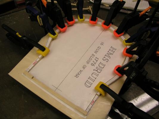
Thanks for all the likes. Big day in the Krug household - time to glue the frames to the jig. I did not glue the outermost frames, saving those for further refinements off board. The keel is still removable. I glued the outermost remaining ones to provide a firm grounding on opposite ends to keep everything in line (the keel riser notwithstanding). I then worked inward gluing one at a time. The frame was pushed below it's required level, the keel re-attached to the existing frames, then the new frame pulled up into position in its slot. Wait a few minutes and on to the next one. As can be seen, the keel was cut to the correct depth and the false keel also cut. No longer any need for the keel risers. Next is to add some frame spacers at the wale location to really lock everything in before sanding, and detail the outer frames. Interesting to note with this building style the keel rabbet is not finished at this time. In fact I used the frames as installed to determine exactly where the rabbet should be. Mark
- 172 replies
-
- 9
-
-
- druid
- sloop of war
- (and 2 more)
-
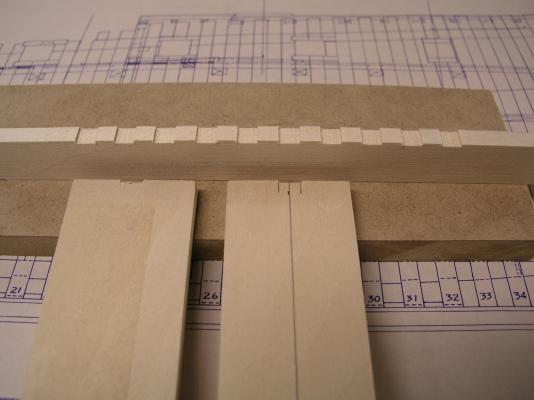
Just continuing to motor right along. The sled on my Byrnes saw almost made this too easy (take'em when you can get'em). I rubber cemented the required keel slot locations onto a piece of basswood (will cut to correct depth later on). After it was dry I adjusted my Byrnes saw to the correct depth and using the sled cut all slots perfectly out in less than 5 minutes (test fitting a frame for each slot as I went). I also cut a slot on the keel height holders - which was a mistake, but no harm done. The keel holder was the proper height of the keel BEFORE cutting. With out the slots, the frames had actually been adjusted a tad too low in the previous pics taken. Amazing how things like this pop up! Glad I caught it now. Then everything was put together with the frames into the slots (the picture has the incorrect slot in the keel holders). Amazing how rigid and strong the structure became. I now need to fix that keel holder and I will be good for starting to drill some trunnel holes as well as cut my purpleheart false keel. Stay Building My Friends, Mark
- 172 replies
-
- 10
-
-
- druid
- sloop of war
- (and 2 more)
-
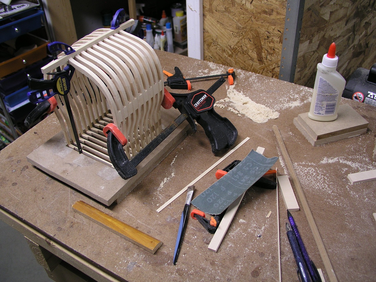
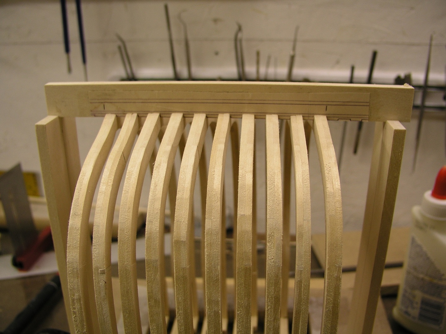
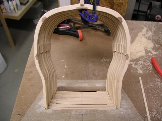
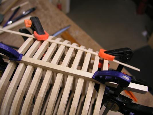
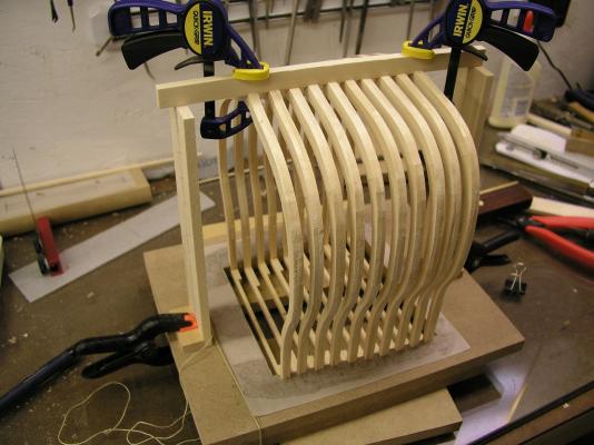
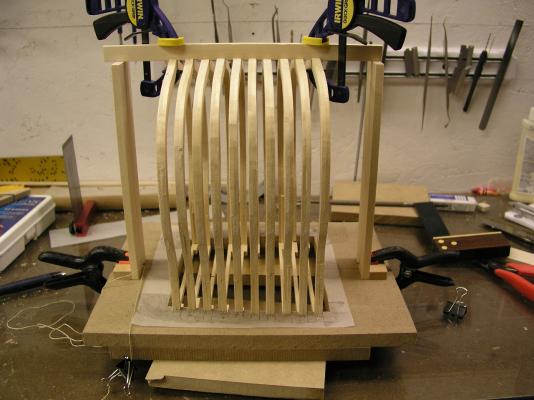
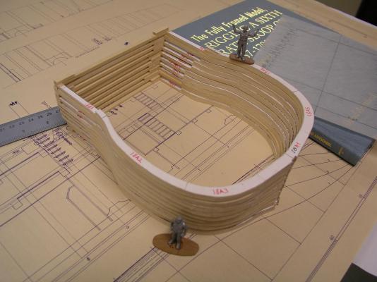
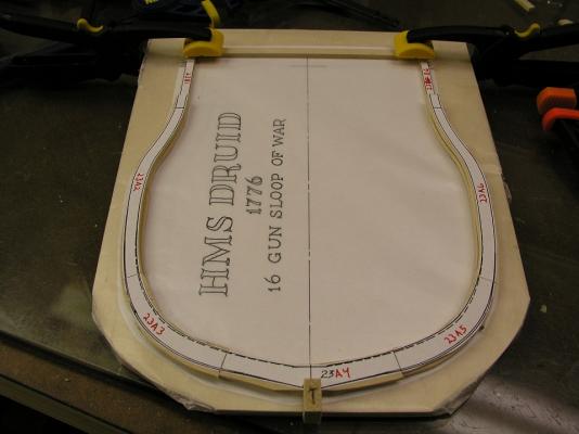
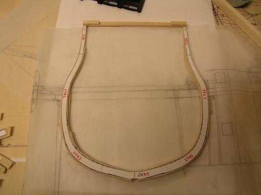
With some free time on this New Year's Day (everyone sleeping in) I dashed down to the shipyard. Things seemed to go pretty fast at this stage. I removed all paper from the frames and added the missing support wood. I then methodically worked the positioning of the ten frames onto the jig. Lots of back and forth to the scroll saw but well worth it. Still some cleanup to do on each frame, primarily around the keel slot before I glue them into the base slots. Then it will be on to the real keel. I know the hull is centered on the jig and correctly positioned. Any measurement on either side will match. The base is parallel to the keel. This should limit the 'surprises' in the future. Stay Building my Friends, Mark

- 172 replies
-
- 10
-
-
- druid
- sloop of war
- (and 2 more)
-
Very clean and nice build Dimitris. Looking forward to learning about how to apply that fiberglass for that finish. Mark
-
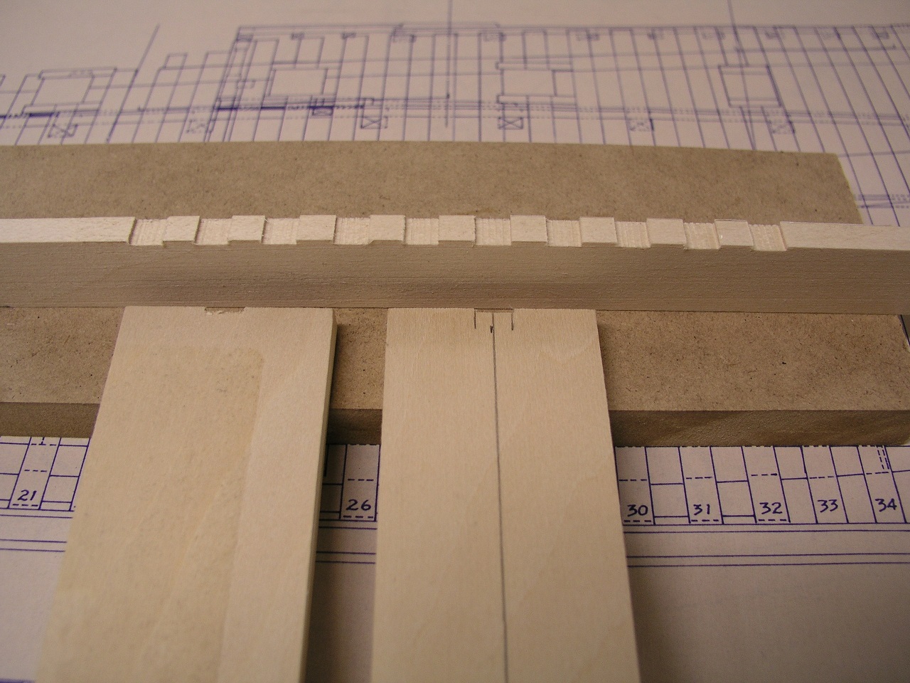
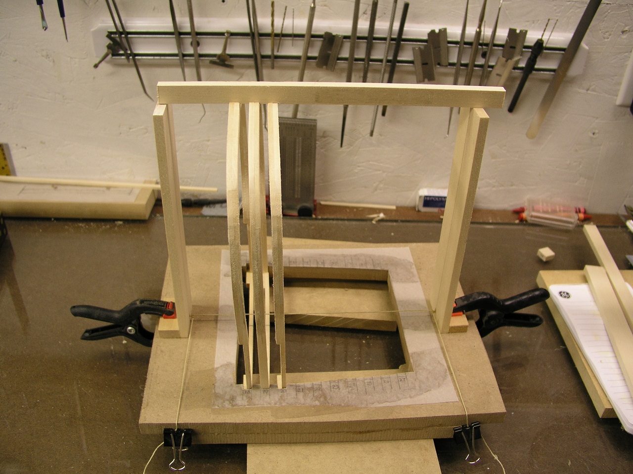
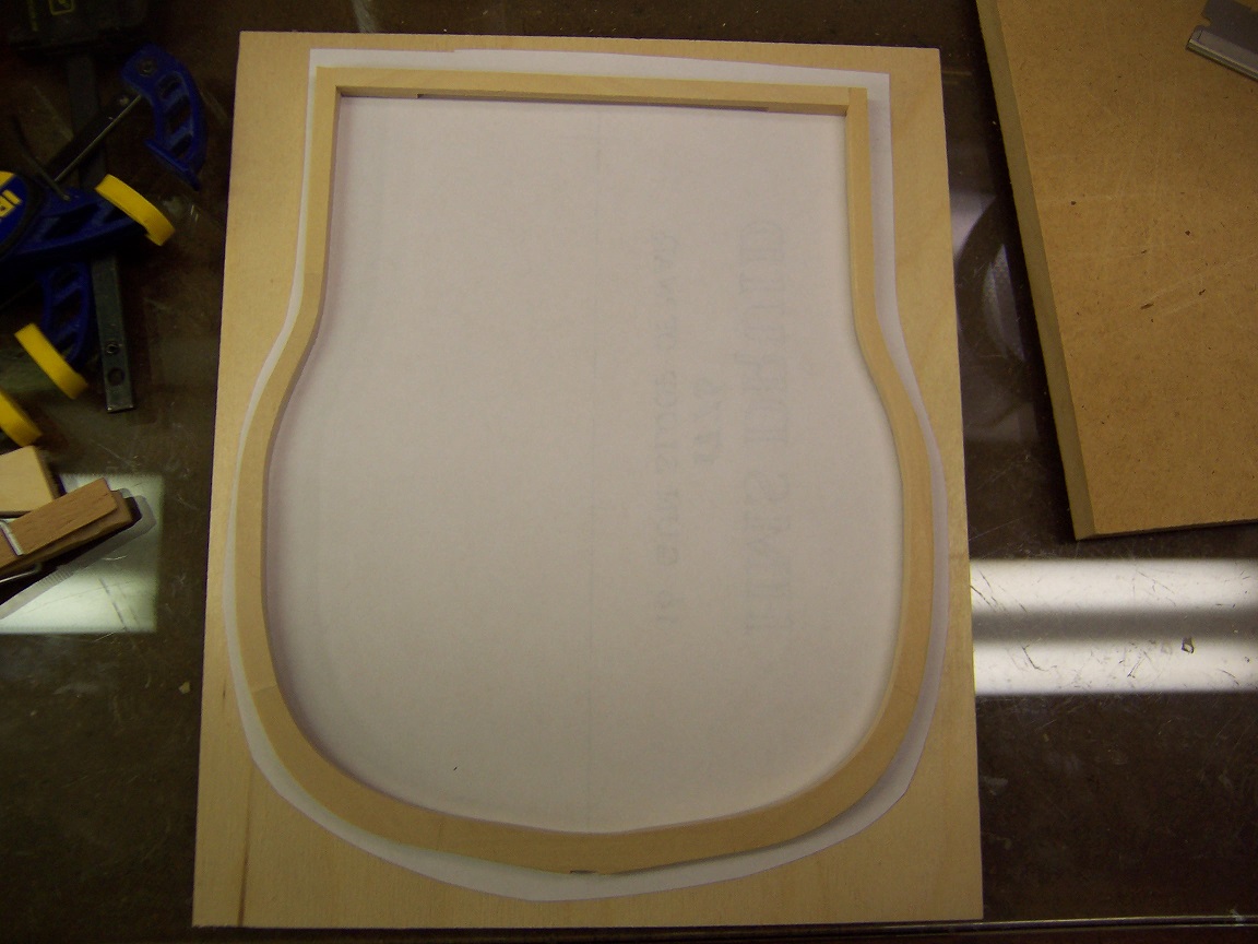
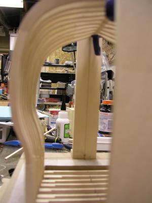
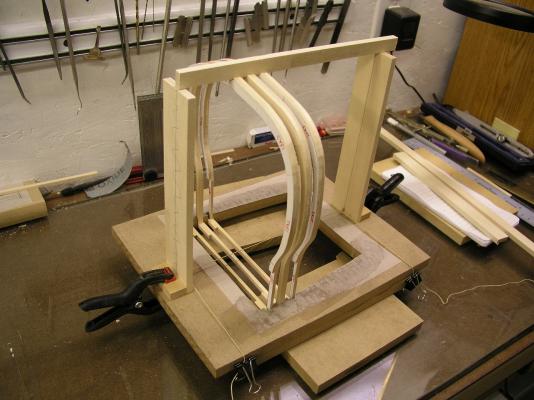
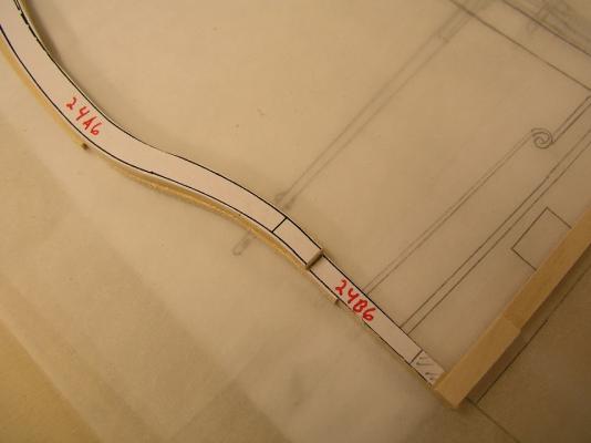
With the frames roughed out it was time to think about how to make the Hahn style jig. I had success previously with the full hull but had lessons learned for my building style (read accuracy and capability). So I came up with the following: First off, I did copy the base pattern off of the plans but did not go and cut it all out at once. Lots of small errors compound to very noticeable ones. So after cutting out the center portion I picked the first frame, centered it over its location then cut out notches for it to fit snugly. I also fit out pillars that insured the keel was at the exact height and centered over the jig. So the frame is inserted into its groove, the pseudo keel is put into position and then the frame is pulled up into position perpendicular to the board. For the next frame I inserted a 1/8" board spacer to define the start point of the frame, then measured as above off of this starting position. Very close to the plans but tweeked here and there. So everything is based off of the first frame. Nothing is glued yet (still have to scrape off the remaining templates). After everything is verified, the frames will be glued and then the real keel will be fashioned. Also need to detail out the face frames of the first and last exposed frames. Stay Building My Friends, Mark


- 172 replies
-
- 10
-
-
- druid
- sloop of war
- (and 2 more)
-
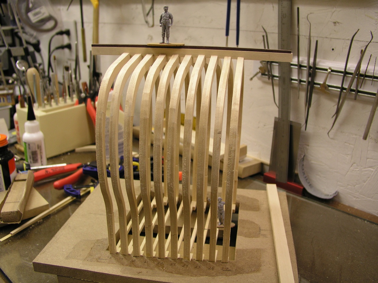
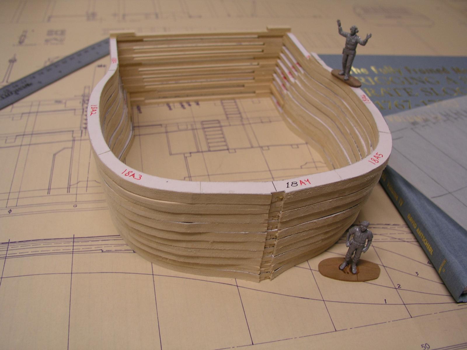
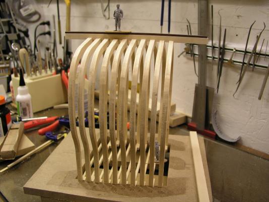
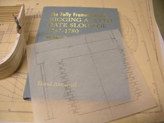
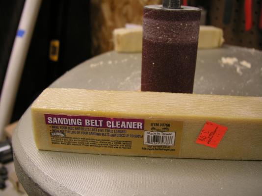
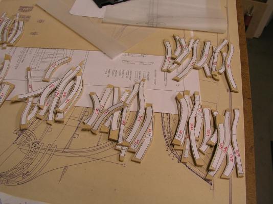
With the holidays (and the family flu) in the rear view mirror I finally spent some time in the shipyard. I finally got all ten frames rough cut out. No bevels yet (after they are installed in the jig) and the face frame sides will have futtock join pieces with trunnels added. You can see one of my Christmas gifts from the kids - 1:48 scale plastic figures. They are Air Force ground crew figures, so some modifications will need to be made, however I really liked the look of them on the full Druid. Nice to see the figures fit so well. They will be all over the cross section: climbing, cleaning, firing - you name it. Next up is to cut out the base jig to hold these frames inverted (the Hahn method). Hope to pick up the wood tomorrow. You can also see the other big gift from the family: Volume IV of the Swan books - AWESOME! BTW: I picked up this sanding belt cleaner bar and it works fantastic. I would highly recommend. It basically brings the sandpaper back to like new. The top of the spindle sander hasn't been treated, below it has. Simply push it against the running drum whenever it is starting to gum up. In other news: The full Druid has been invited to another Art Showing for January in Lowell, Michigan. This will be followed by a request for a business to host for another month. Tremendous positive feedback. Stay Building My Friends, Mark

- 172 replies
-
- 13
-
-
- druid
- sloop of war
- (and 2 more)
-
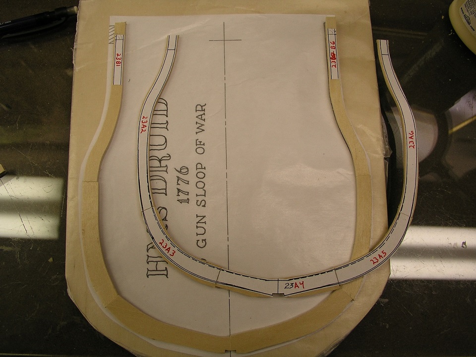
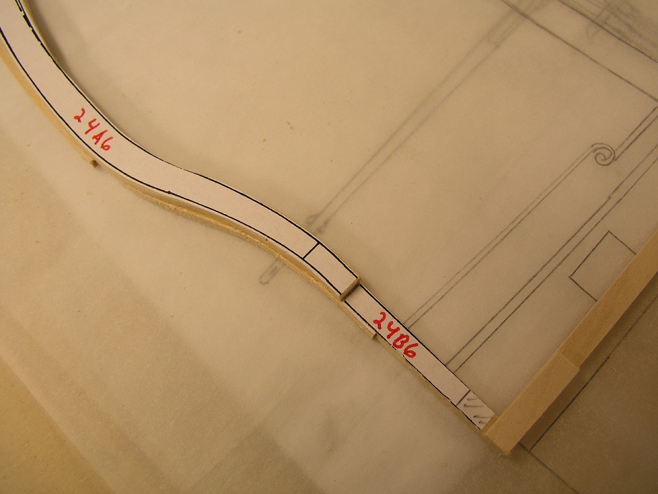
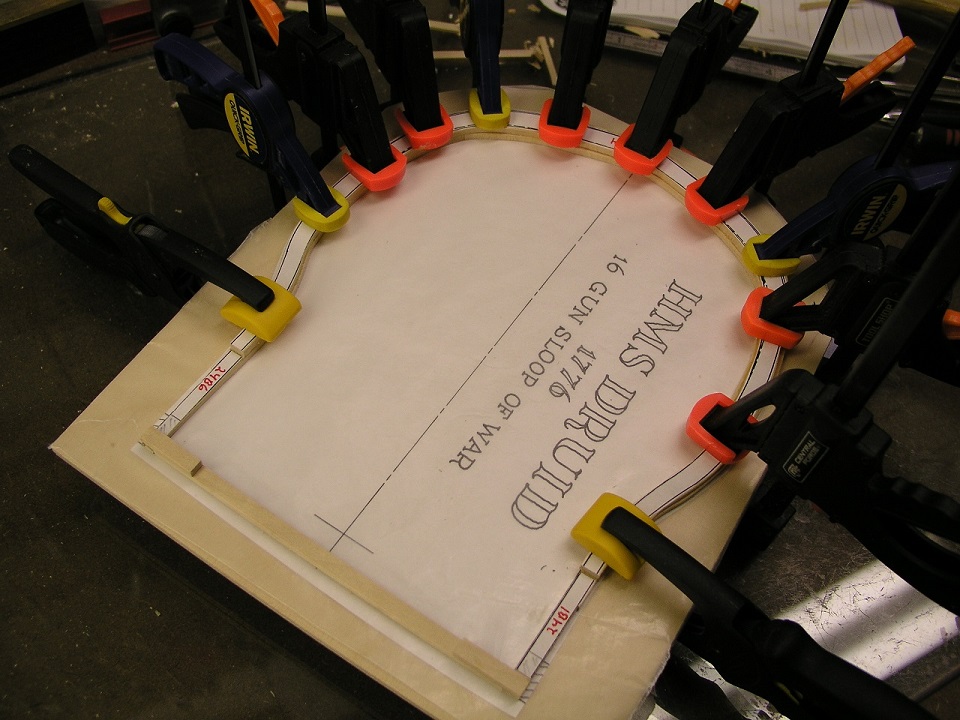
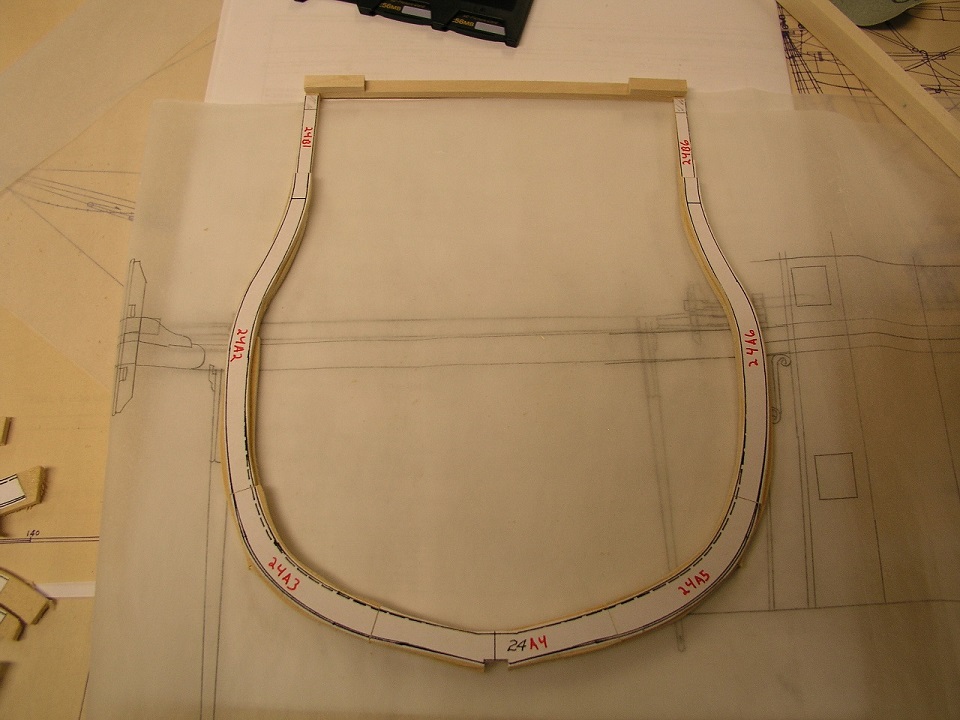
In the Army there is a saying that no plan survives first contact, and it looks like it applies to ship modeling also. After butchering a frame and a half I took a step back and reevaluated how I was making the frames. After punching out three successful frames I have found what works for me. I still used the rough cut out futtock pieces (trying to get a 1/16" buffer around). I then proceeded to exact cut the join edges without refining the other edges. The layers were then independently glued together over an uncut picture of the frame. I omitted the upper pieces on the top layer to allow both layers to be aligned. Then using a faux keel for center alignment and matching the upper parts of the frames the frames were glued together. For the final steps after drying I used the spindle sander to finalize the frame outline and removed the last of the paper templates. This is what worked for me. Now just to get the rest of these frames finished off (if I can keep the rest of the family from getting the flu). Stay Building My Friends, Mark


- 172 replies
-
- 8
-
-
- druid
- sloop of war
- (and 2 more)
-
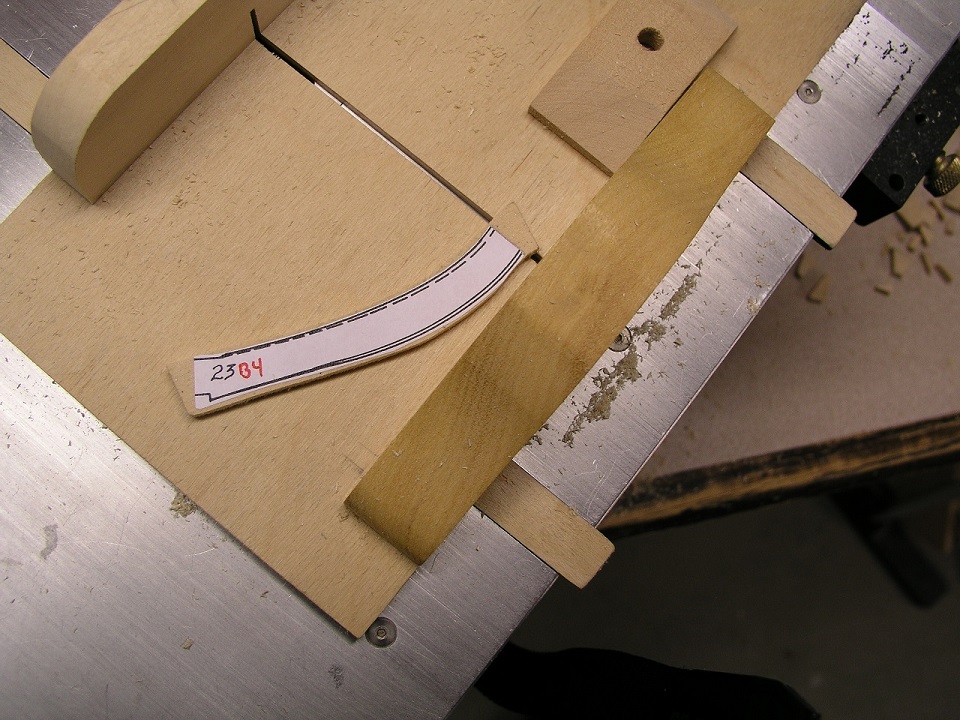
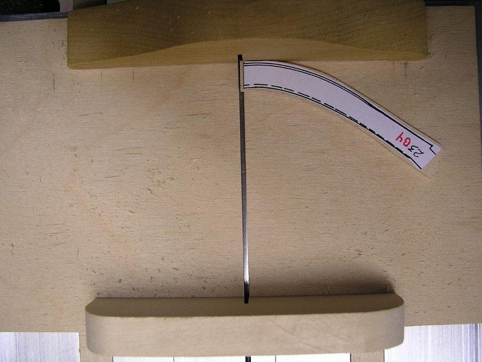
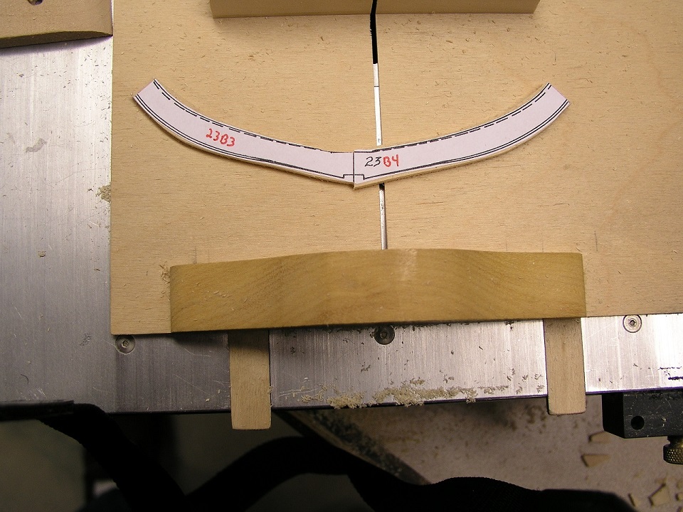
Okay, I think I understand now - the reference plane used on the sled is the zero clearance slit. You are correct, because of the curved futtocks I cannot clamp them against the back wall. I do try to hold at least a point of the futtock against the back wall to insure when the blade makes contact the piece is not pushed out of alignment. The alignment is with the zero clearance slit that the blade travels through. So I look down across the targeted cut and its alignment with this slit. I do not go for the money cut right off but pair the excess away so I am less than a blade's width excess when making the final cut. The pieces are pretty light so small pressure downwards on the piece is sufficient to hold it to the sled through the cut itself. The back wall of the sled also includes the zero clearance slit so that is actually easier to line up. Additionally remember that every cut is 90 degrees to the blade. So when I align the bottom forward part of the futtock to the slit this mirrors the effect on the top. As each cut is engaged you can see the accuracy with respect to the paper template (but it will always be dead on straight). Obviously the goal is to never get too heavy with the cut, but walk up to the cut. I can shave very small adjustments by doing this. I am 'hoping' to get back to the shop tonight and will grab some shots. For the general audience: I am pushing the futtock down onto the sled, but the force to push the sled is exerted by thumbs behind the rear fence well out of harms ways. As well the blade just clears the futtock height. This is very controlled. With the sled and futtock essentially becoming one piece you have safe control of what is occurring. Mark
- 172 replies
-
- 1
-
-
- druid
- sloop of war
- (and 2 more)
-
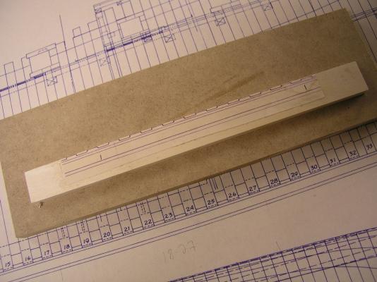
Chuck, On the full frame plans I determined first where the futtock lines will reside by annotating points on the outside of the frame. I then essentially eyeballed close to a 90 degree cut across the frame and penciled this line in with a straight edge. After cutting out the entire frame and insuring the individual futtocks were sequentially numbered, I cut across these lines to define each individual futtock template. This insures the cut angle is absolutely true futtock to futtock. Does that answer the question? If I ever lost any of the futtock templates, it would take a bit of work to redefine a replacement to insure these angles are true.
- 172 replies
-
- 2
-
-
- druid
- sloop of war
- (and 2 more)
-
I cut scale planks but always have a longer working plank to push up against it to validate the same flow is present. This also insures you don't artificially have the plank run where a stealer or different width is required. You want to avoid the start / stop look at each plank end caused by slightly different plank angles. Mark
-
Wow, you are really re-thinking things here! Great job on the re-work. I was starting to get worried that the next post would see the hull stripped down to the bulkheads and you reworking the lines! You are getting sucked into scratch in a big way. Beautiful ship. Mark