HOLIDAY DONATION DRIVE - SUPPORT MSW - DO YOUR PART TO KEEP THIS GREAT FORUM GOING! (Only 20 donations so far - C'mon guys!)
×


kruginmi
-
Posts
629 -
Joined
-
Last visited
Content Type
Profiles
Forums
Gallery
Events
Everything posted by kruginmi
-
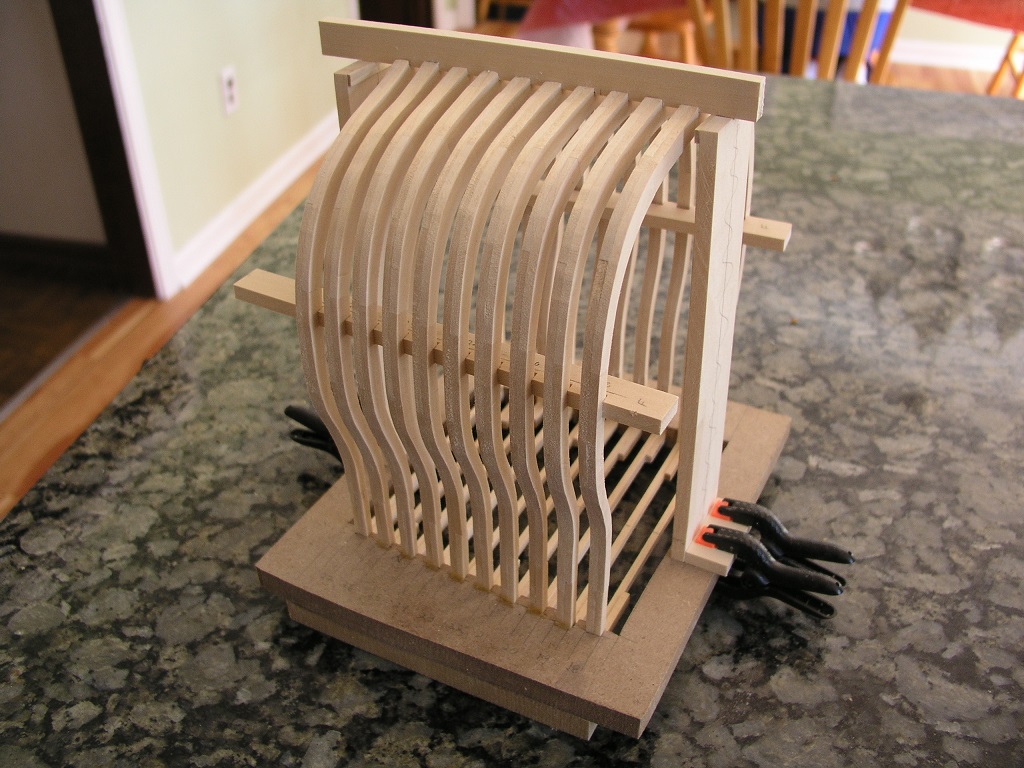
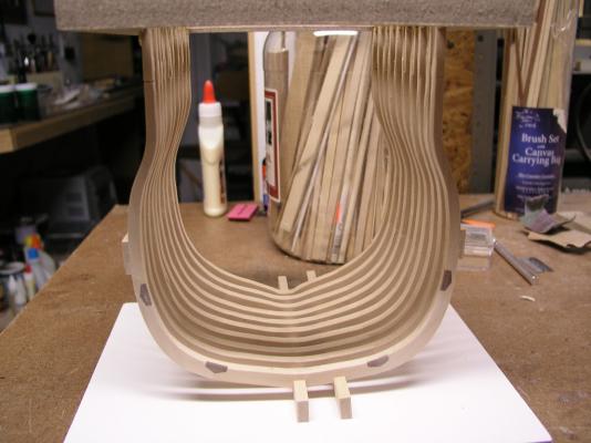
 Thanks for all the likes and words of confidence. This is just something I have to learn to live with, probably won't be my last! Focused on getting the thickstuff in the hold. With all the work to define where the futtock joins are (and thus the thickstuff placement) I am a lot happier with the result than the first go round. Next up is to use add the adjoining layer (3/32" basswood) next to the thick stuff (1/8" basswood). Regular planks will be with 1/16" basswood. I should have the lower hold buttoned up within two weeks. The exterior hull will also be totally planked. Sure feels good when you cut something for one side of the build and it also fits perfectly on the opposite side. Stay Building my Friends, Mark

- 172 replies
-
- 14
-

-
- druid
- sloop of war
- (and 2 more)
-
Sorry Nils, but 2.5 - 3 years for a 'normal' experienced builder (actually probably more like 3 to 4). You, I am betting on under 2 years to completion. Mark
- 2,625 replies
-
- 4
-
-
- kaiser wilhelm der grosse
- passenger steamer
- (and 1 more)
-
Cautionary note that you probably are aware of: The plans are 2D and the ship is 3D. By draping the plans over the hull, any curvature in the hull will introduce errors in the 2D wrapped plans drawn to the hull surface, usually most pronounced at the bow or stern. Be very careful of the adjustment variances introduced. The biggest concern is the height of the ports off of the installed internal deck. Good job so far, especially on the work on the transom and not giving up! Mark
-
An important point to consider is your choice of seat. The question is less height off the floor than height off your sitting position. If you haven't picked out a dedicated chair/stool, now is the time to do it. Then figure out your optimal resting hand / elbow height to figure out the gap between chair and table top. Then add your chair height. Sounds more complicated than it is, but get it wrong and you have lasting issues.... Mark
-
Hey, look at me, I can glue a deck clamp! A long story (with a pretty happy ending so far...): I turned 50 in April and always knew this was going to be a breakout year. Not to linger on the point but after a series of events I was diagnosed with a rare disease (Mommy always said I was special). A few specialists and then a 3 week hospital stay I was back dealing with all the yard and house work that backed up. But tonight, tonight I returned to the yard and cut and glued a deck clamp. Well, that went so well I completed the keelson: Not too much, I know, but a sign of things returning to normal. Now I have to look at a sprint Triathlon in less than 60 days and a lot of training I am behind on so who knows when the next update will be posted, but make no doubt there will be more. Stay Building my Friends, Mark
- 172 replies
-
- 14
-
-
- druid
- sloop of war
- (and 2 more)
-
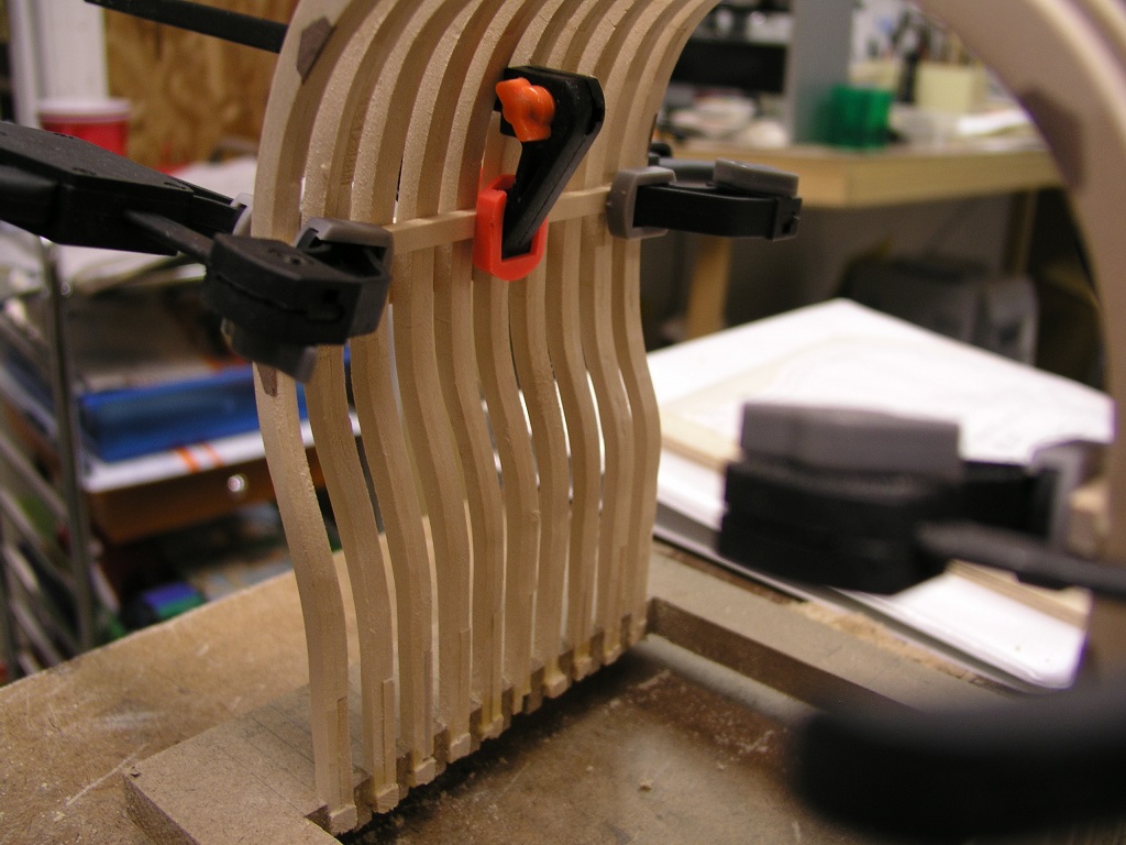
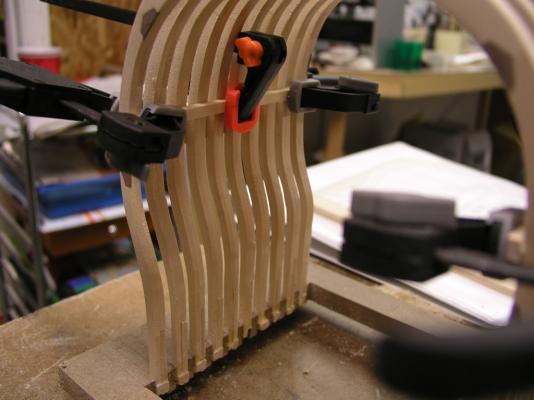
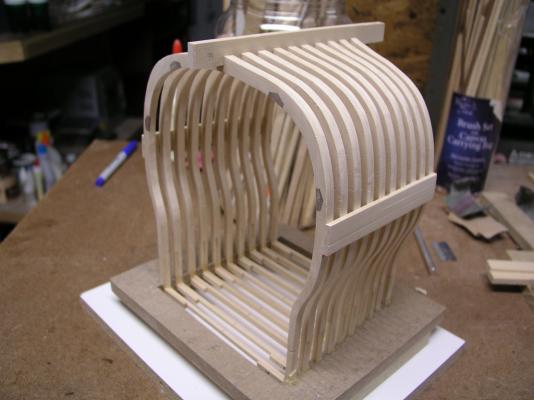
Thanks Eamonn and all the likes, Still slogging ahead as time allows. I have attached all three strakes of the wales both port and starboard. I am still using the extra deep slotted keel jig for holding everything together. I have also opted to skip the frame spacers. Using another deep slotted keel jig I insured correct spacing and glued the wales (freezing the frame spacing) then removed the slotted jig. Fairing has occurred only over the wales area - which was pretty easy. Now that the frame has been stiffened I can easily fair the rest (externally). Next up will be removing the frame spreaders and then work on the internal fairing. As is evident in the pics this will not take too much time. Very soon start affixing the thick stuff in the hold. Stay Building My Friends, Mark
- 172 replies
-
- 10
-
-
- druid
- sloop of war
- (and 2 more)
-
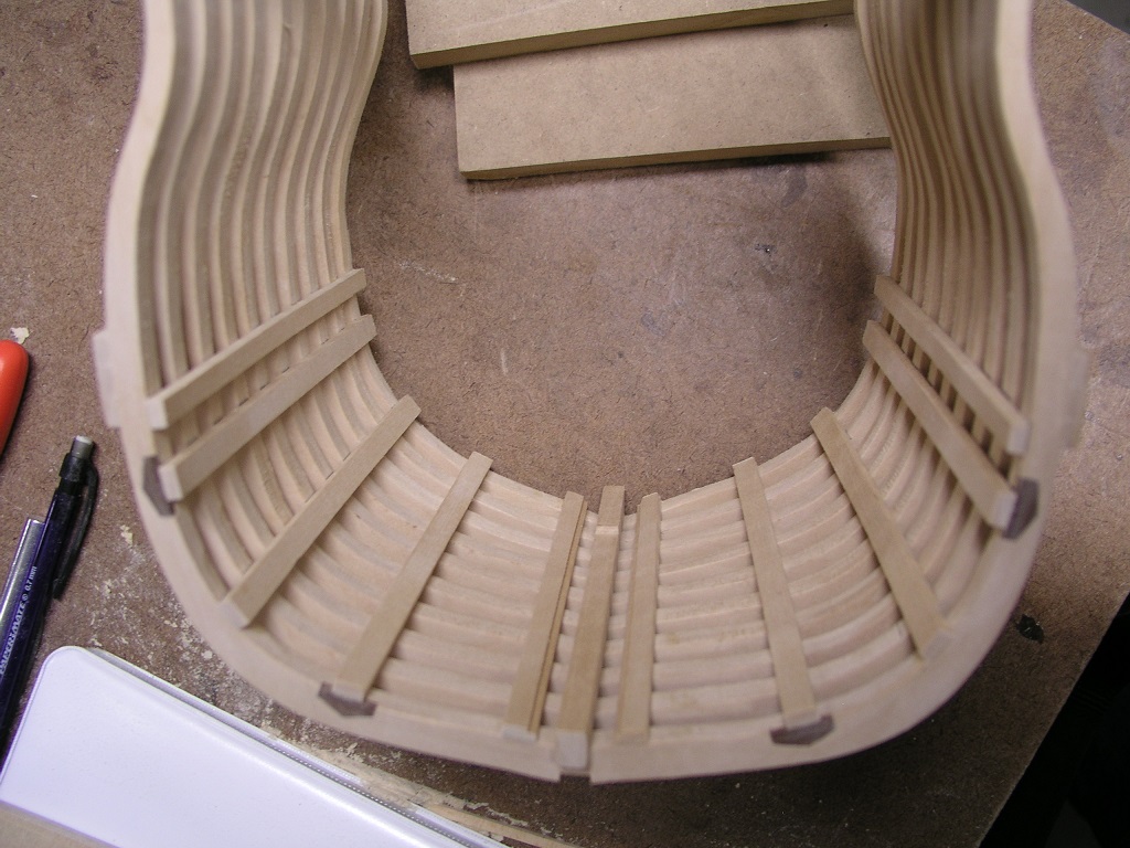
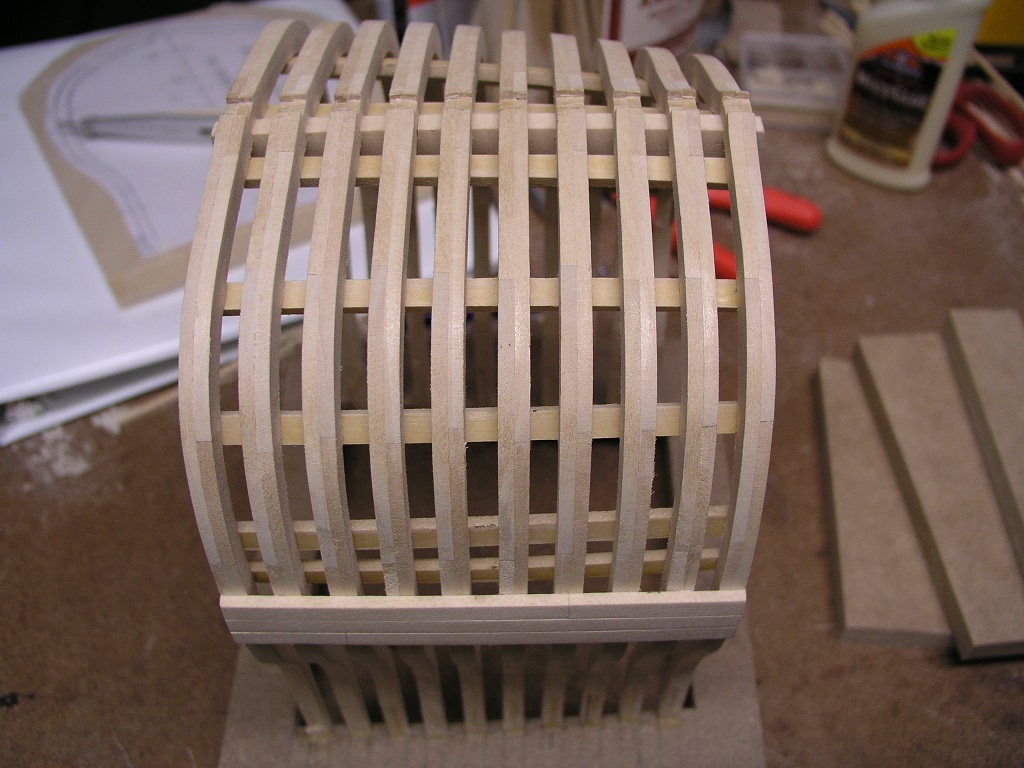
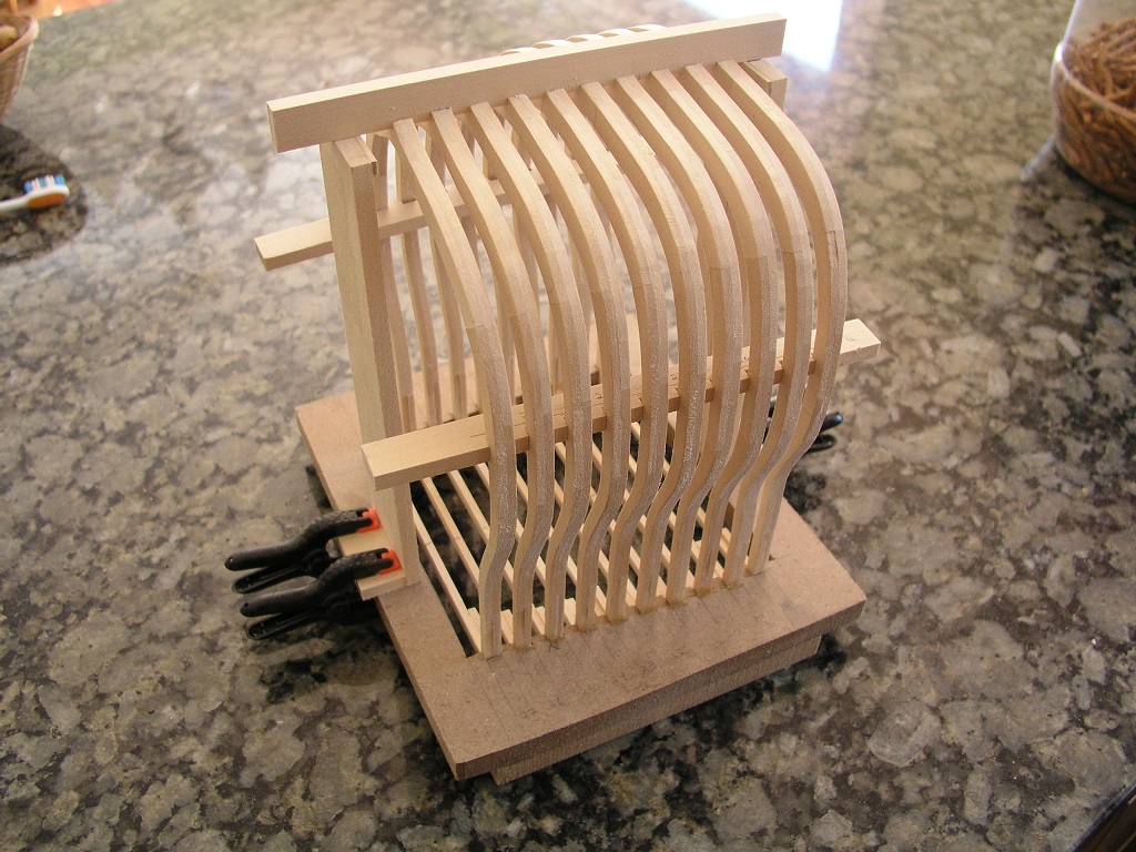
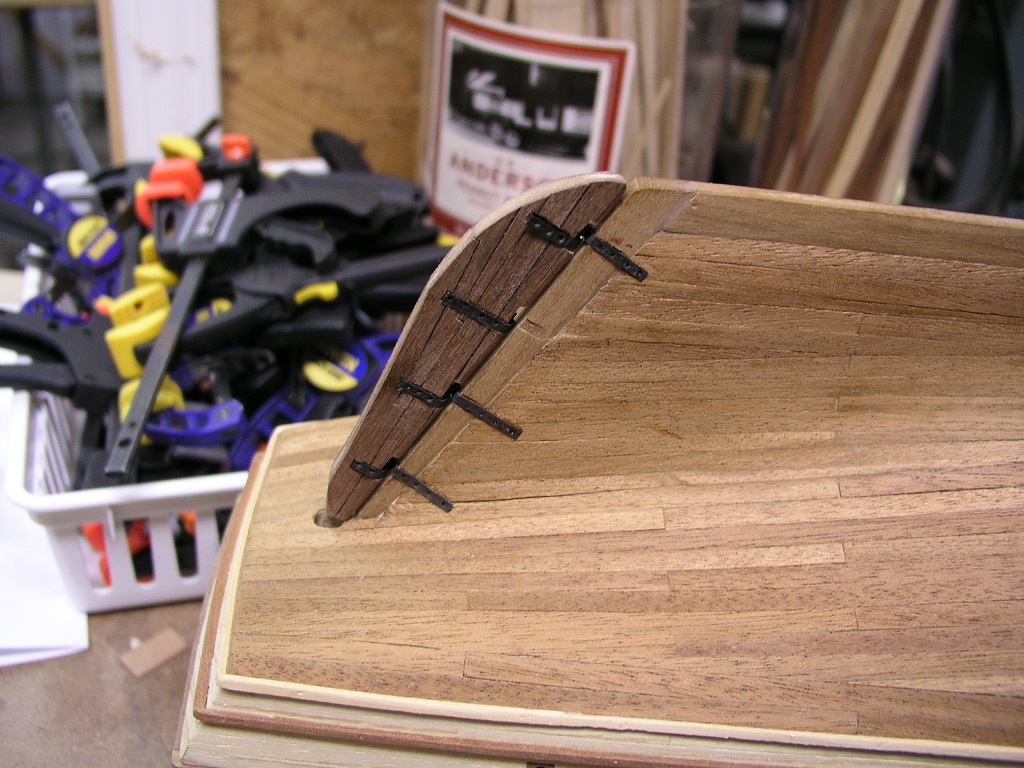
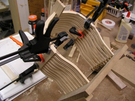
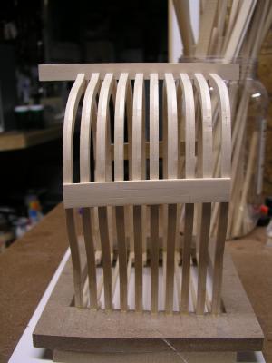
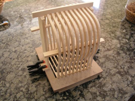
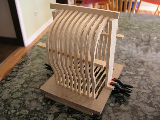
To use a phrase from Monty Python: 'Not dead yet.' Slow but sure the new frames have been generated. Everything triple checked and locked in. This morning I glued the framework to the base jig (excepting first and last frames) and everything is in its proper place: I need to add the walnut chocks to the 18th and 27th frames prior to gluing those in and then fair the hull. The hull is already so close to being smooth, which is how it should be. Shouldn't take too much effort. I did add removable spacer blocks (in the pics) at the mid-points either side and will probably not add spacer blocks. Once the mid-section is good to go I will add the wales for strength. One other difference from previous attempts was to get all the frames in place insuring everything measured out correctly before gluing anything. I only added glue once in place and pushed it around where the frame and the bottom jig intersected. No chance of it grabbing prior to being in its final place. Mark
- 172 replies
-
- 11
-
-
- druid
- sloop of war
- (and 2 more)
-
Beautiful. You really should add a ruler to the shot so people realize just how big that ship is! Keep up the momentum! Mark
-
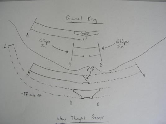
All right, I guess when you wake up in the middle of the night with a question in your mind specific to chocks, you are probably not on an even keel (pun intended). However, the question raised in my mind did end up raising others. I am doing a lot of studying of the TFFM HMN Swan Class Sloops books and for those that have them (for this discussion volume 1) I will include references. For others I apologize but don't want to include copies of the contents. My discussion centers around this diagram: At the top you can see the way I originally made the portion of frame 18 which straddles the keel, which is composed of two sides laminated together (split apart here). In the rework and elimination of one of the joins (see page 190 TFFM V1) this has caused the the piece going across the centerline to collapse into a much smaller length (denoted as the B piece). The other side was simply cut across the centerline straight down and had a chock added for strength. This is the issue - it didn't seem right to put two chocks against each other which would happen if I added them the same way to the B piece (which would then overlap the A piece chock). The view of Page 190 seemed to show a chock at the centerline as I originally created them but the companion side seemed in question. I found on page 156 a good view of the bottom connection superimposed which leads me to believe that the bottom joins do not have chocks at all. I have redrawn this view below the others. I am thinking that the line denoted by 'V' has been left off the view on page 190. This is backed up on page 140 of the actual pics of construction Mr. Antscherl provides of his Tisiphone class ship and the build up of a frame pair. Having drawn this out it is also revealed that the second futtock B will require around 17 square feet with a good curve to it. This is a natural occurrence of going from 7 futtock pieces for this frame to just 5. Being a cargo ship this has a much fuller body than the TFFM plans shown amidships. I am thinking I might need to add an additional futtock (and thus another set of thickstuff) back in to each side to cut down the 17 feet. I will go back to the original 4 in the hold each side. I am also thinking of eliminating the chock at the centerline and going for that more complicated join. Again, good news is that I will really only have to do this join on the extreme aft and extreme forward frames since all else will be covered up. Thoughts? Mark
- 172 replies
-
- 3
-
-
- druid
- sloop of war
- (and 2 more)
-
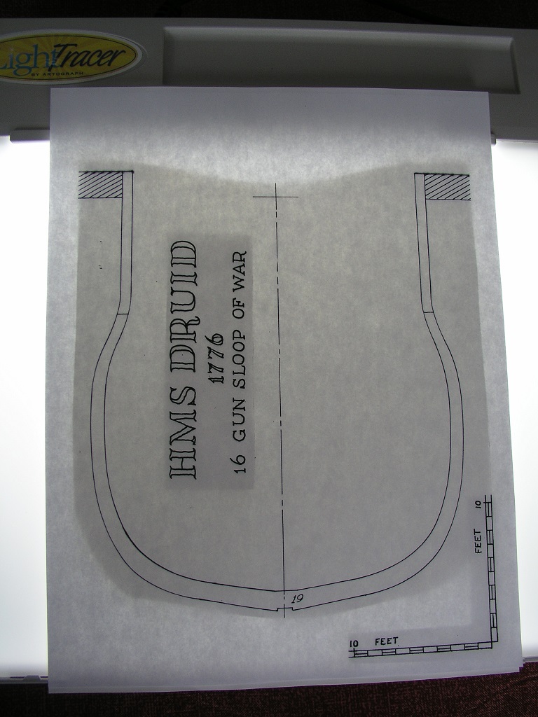
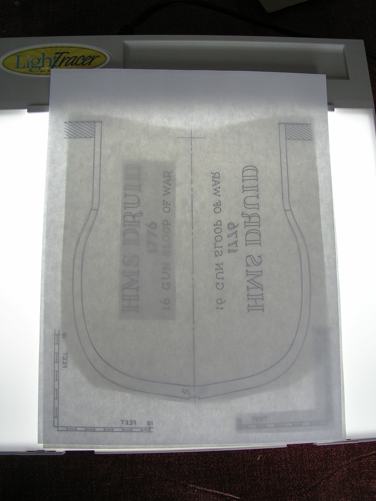
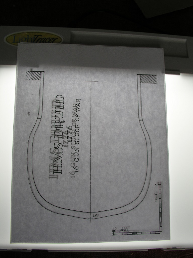
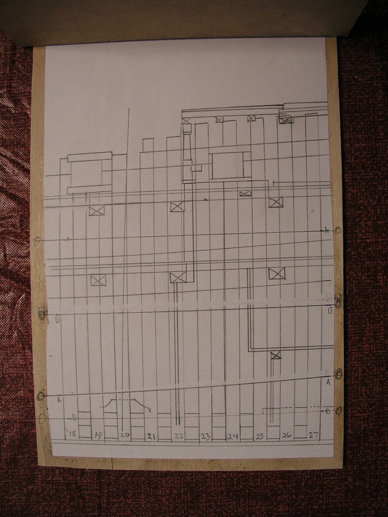
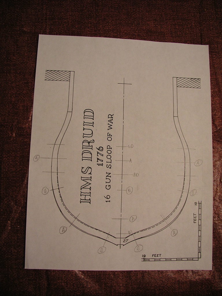
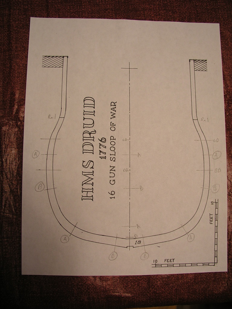
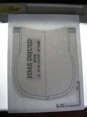
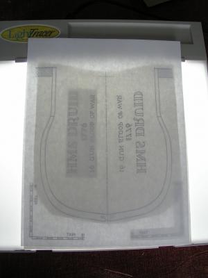
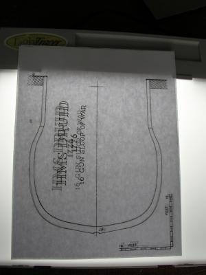
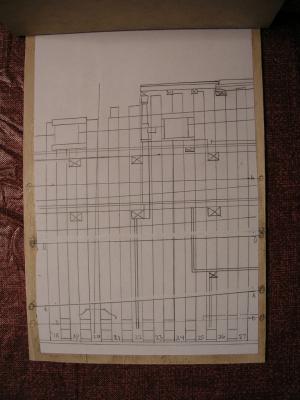
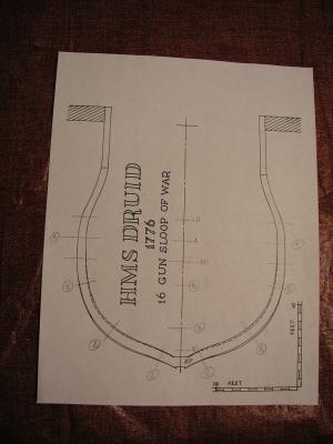
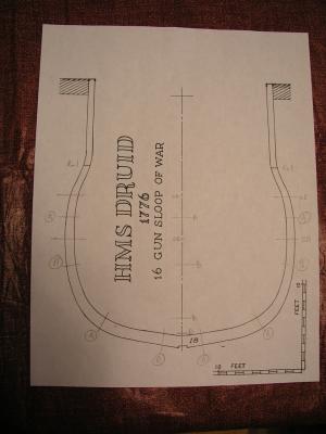
Onto a fresh start. First thing was to confirm(!) the photocopies that I had produced. First I compared the copy with the original: Then I flipped the copy over to very the mirror image across the center line: Finally I compared the frame copy to the previous/next frame: Using the light box this was pretty straightforward and showed within a small margin everything was consistent. So I am good. Well almost.... I need to figure out where the futtock joins should occur to give me the right lay of the thickstuff within the hull. I started with frame 18 and with the centerline defined the berth and gun decks. Then I defined the two sets of joins (denoted as A and B on the following pic). I wanted one to be defined midway between the berth and gun deck, one for the limber strake, one just below the berth deck and the last to fall in between the previous denoted joins. The same was done on frame pattern 27. After defining the joins all the heights were transferred to the centerline: Transferring this measurements to the side view on their respective frames and I connected the dots to define the correct heights for all the rest of the frames. The joins are denoted by a circle through the line: I have never really seen this technique required but definitely should provide a good consistent set of joins. The middle join really shows a rise on the profile but defines a midway location at each point. Comments are always welcomed (especially prior to cutting wood once again!). Is there anything else I need to think about? Mark
- 172 replies
-
- 3
-
-
- druid
- sloop of war
- (and 2 more)
-
So what caused me to take this action? Numerous small cuts that added up to a real bleeder! - The frames had some real issues with aligning. I had to make adjustments at numerous times. With all the care I took up front this caught me by surprise. - Being totally honest, I was seeing non-uniformity in the final widths of the frames, to include same frame and between adjoining frames. Not much but millimeters equate to some real distance - Even the spacers gave me fits, causing some alignment creep. - I started to get the feeling that all my alignment fixes had given a little twist to the hull - The final straw was I just happened to do a cross section length check and there was variation at different points. To the eye you couldn't see this issue but the ruler betrays all. Each specific issue was seemingly small and could be 'easily' fixed. However, you always get bit when you do this and leads to other issues. I just finally had enough. Now, I am not going to throw this in the trash. I am hoping my 10 year old will take it and eventually put his finishing touches on it, so for now it goes into storage. Another factor was realizing the specifics of how the thickstuff aligns with the joins. My current joins seem too close together. I realize now you do not measure these out in isolation but look at the side plan of all the frames and figure out the sweep you are looking for. As an end note though, when I really looked at the copies of the frames I used and saw how distorted they were, particularly on the port side I had found the smoking gun. The issues I had been finding hadn't been because of my workmanship (well, other than not checking the frames). I could do this and do it right. (Note: The Hahn drawings are right on - no issues there). Mark Plus Mark T. I didn't have a whole ship hull invested! That is a whole other level of backtracking.
- 172 replies
-
- 3
-
-
- druid
- sloop of war
- (and 2 more)
-
No worries, the build will happen. My enthusiasm remains strong (one of the reasons I am doing this!). Went to the copy center over lunch and it took three tries before I found a copier that didn't move things around too much. People wondered what I was doing pressing the copies and master to the window. I had hoped they would have a light table to make this easy but they just looked at me with a blank stare when I asked. I will show some of the pre-checks to do (even with bulkheads) and my hope is to start constructing new frames this weekend. Lots of pre-marking to do to better define the futtock joins and deck beam locations. Mark
- 172 replies
-
- 2
-
-
- druid
- sloop of war
- (and 2 more)
-
I have come to a decision. After an honest / personal appraisal of how this build is going and the little quirks that I keep adjusting to, that little thought started creeping in - should I continue with what I got? This morning I got out a light box and went back to the copies I used for the frames against the plan drawings and there was some significant distortion. I knew better and should have found this out right away before cutting out any wood. Oh well, this is a hobby for fun, right? So....I am going back to square one and starting over. At least I can incorporate better thoughts on join location and how the thickstuff will lay down. I started feeling better right away after making the decision so I know it is the right one. I will continue to use this same build log - however I may be off line for awhile since making frames will be the same as previously shown. Mark
- 172 replies
-
- 4
-
-
- druid
- sloop of war
- (and 2 more)
-
That looks awesome Steve. Once you have the right equipment it actually is pretty easy. Mark
-
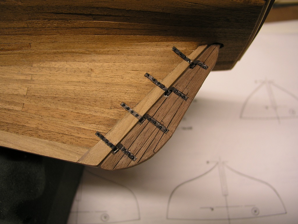
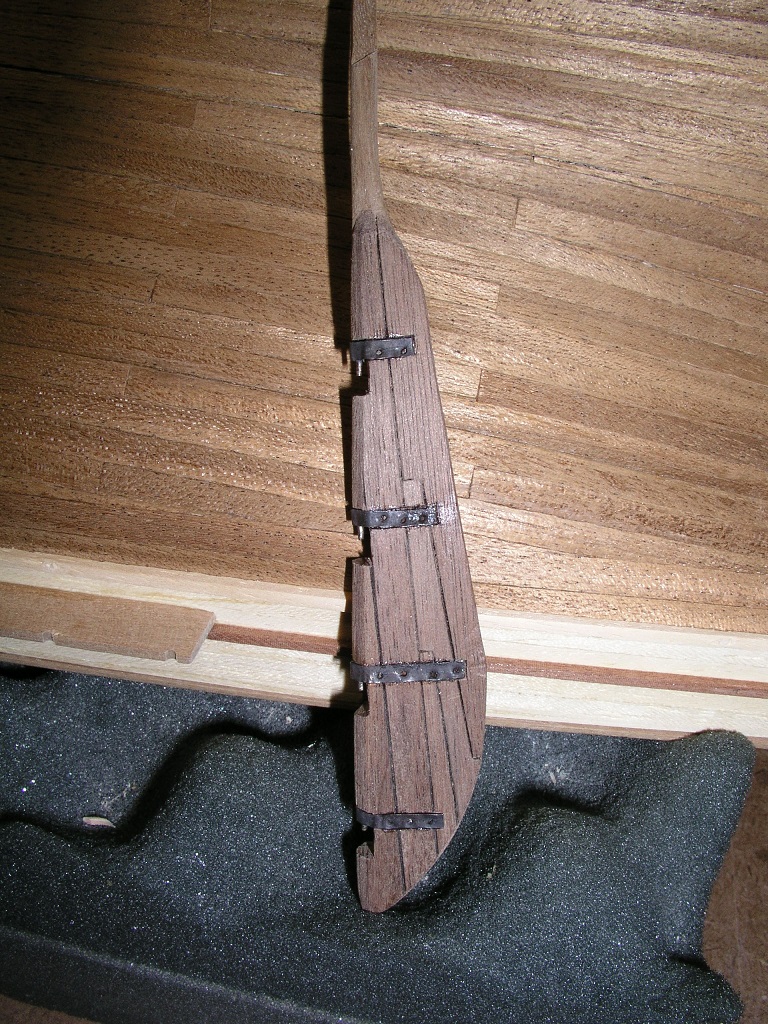
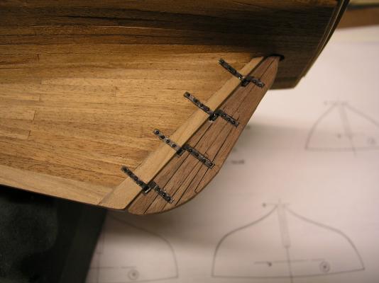
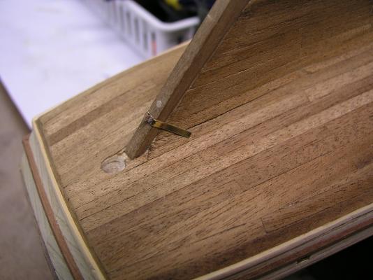
Back in the shop working to complete the rudder assembly.... I first added the metalwork to the rudder itself. I figured out where it should fit and mortised in a channel to insure the metalwork went were it was fitted everytime. In this view I have not installed the bolts. Next up was getting the matching work on the hull. I started with the top most hinge first and again mortised in the location but this time only on the rudder post. After rough fitting I cut the bolt holes into the brasswork before final fitting and then blackening. The issue here was to insure you installed the mating pieces so the rudder will fit into them all at once in a somewhat centered location. The second hinge installed was the bottom and only then the middle ones. Check, check and recheck. This view shows three complete hinges installed without the bolts: Finally after a bit of work you can step back and see the final effect. Since this was a working boat I didn't want the perfect rudder workings and achieved the effect (without any extra effort - of course). hah hah. Now to work the steering mechanism. Of course I have decided to add a ships wheel and drum just forward of the tiller arm. More lathe work but how could I settle on something different? I also need to clean up the top of the rudder with the leather gasket - will help to get a good look to the stern below the tiller arm. On a side note my time is already getting a little compressed. Even though the temp is just above 0 degrees Fahrenheit I have set my sights on three sprint triathlons this summer meaning training has already begun - 45 minutes on the bike this morning (on a trainer in the basement). Oh well, staying healthy will hopefully mean more years to build. Long term gain for short term loss. Mark

- 128 replies
-
- 3
-
-
- artesania latina
- Finished
- (and 2 more)
-
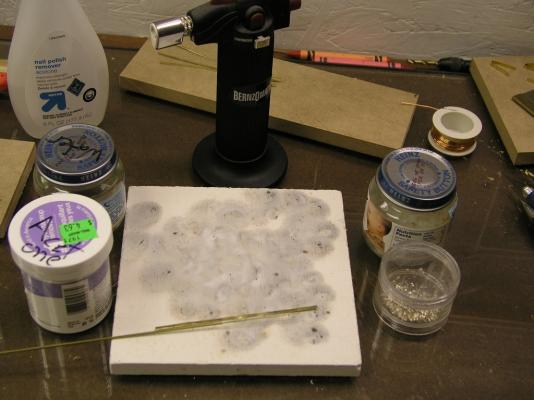
J, My belief is that a torch is pretty much required (I bought mine locally for ~$25). You put the chip right next to the join and heat. Any sort of iron would need to really target where the heat is applied into some really cramped places. Refillable with butane, really easy to fire up. I don't know if I have mentioned, but a heat pad capable of absorbing high temps is also required. Mark
-
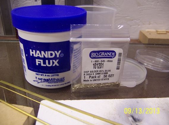
I cannot do any sort of exhaustive comparison that is for sure, but silver soldering is so straight forward and so strong it is what I use. I was fortunate to be led to the setup I have from a jewelry-smith (again, if it is standard for jewelry another reason to use it for ships). BTW: my flux dried up previously and I tried all sorts of stuff that didn't work - the silver chip refused to melt. I finally ordered the flux originally told to use and wham o - instantly back to success. You can also get silver solder at three different melting points to allow complex joins from different pieces without worrying about undoing previous solders. I haven't required this as of yet. My bag of silver solder chips will probably last until I am 6 ft under. The smallest piece is usually more than sufficient. Mark
-
Thanks for all the kudos on the hinges, but give me another hour or so in the shop to make them really pop - then people will see why I went this direction! Lots of bending now for a good tight fit and correct profile. I will slightly mortise these onto the rudder. Eamonn, spot on with your work. Absolute key to silver soldering is using the right flux (then prep). When all is well, this is quite easy. You heat the piece carefully until the silver chip simply disappears - wicks into the join. Cool off with water and then on to the next. Mark
- 128 replies
-
- 1
-
-
- artesania latina
- Finished
- (and 2 more)
-
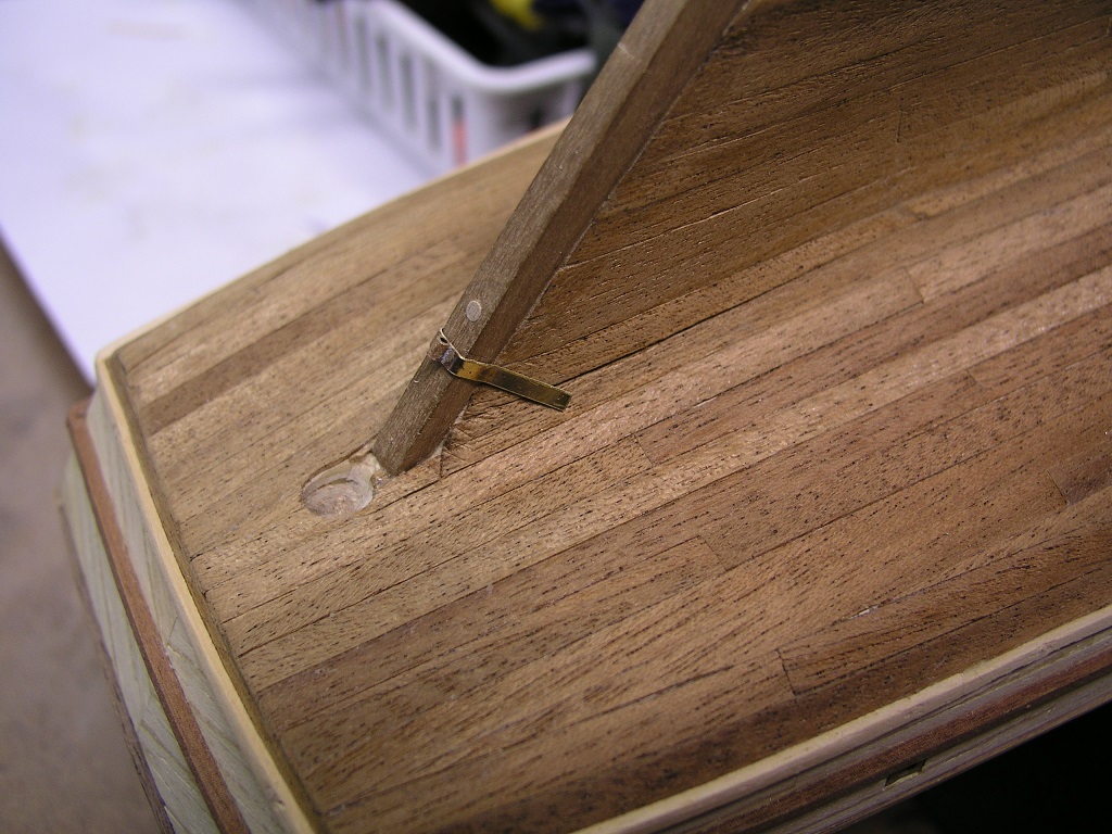
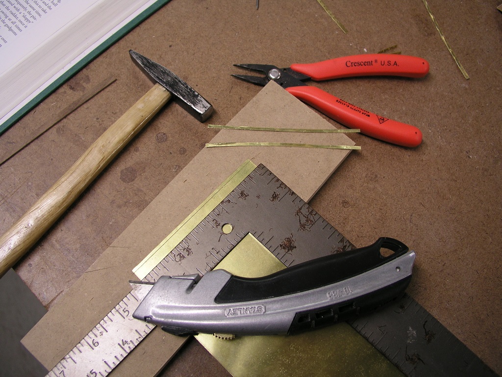
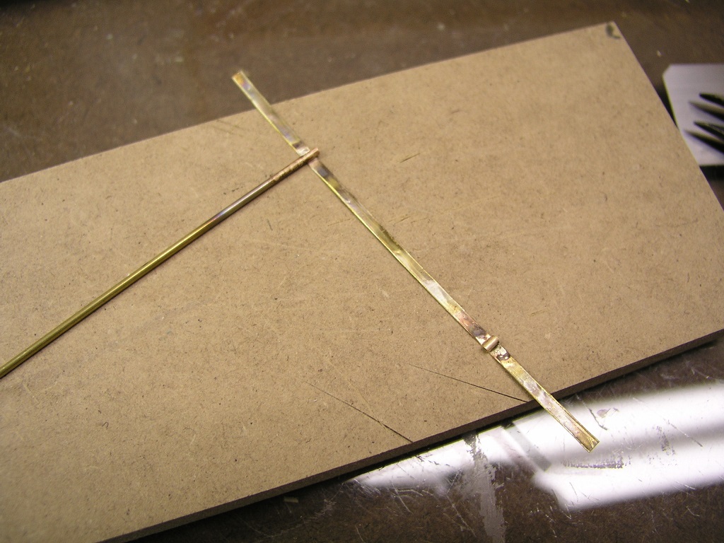
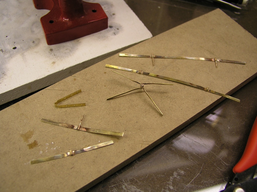
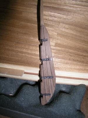
Onto the rudder hinges. The generic hardware provided with the kit just didn't do it for me and with the success of the built ones for the Druid I really had no choice (hah hah) but to go down the same route. First up was cutting strips for the 4 hinges required. My raw brass sheet was wide enough to provide enough strip for each hinge set. Simply define the width and run the blade over this line a few times. I then gently wrap this edge over the edge of a piece of wood using gentle hammer strokes followed by returning it flat. Then I grab it with my small pliers and with a little wiggle the strip snaps off. I had previously bought a brass tube and rod that perfectly fits inside for the hinge mechanism. For silver soldering there has been lots of posts but essentially the ingredients are: Acetone for cleaning the brass, water for cooling after, flux (the right stuff), the silver solder pieces and finally the torch. The tube was first soldered to the strip and then cut to size. After repeating this eight times I then soldered four rods for the mating pieces. After it was all done (less than an hour) I did an initial bend and everything looks good. Still some refinement but another hour or so and these will be ready for blackening. The original kit piece is in the upper left. Very solid (and permanent). It will look like a million bucks soon. Next step is to drill holes for the bolts, bend to shape and get them configured to the hull. Stay building my friends, Mark


- 128 replies
-
- 5
-
-
- artesania latina
- Finished
- (and 2 more)
-
Is there a better #11 blade handle
kruginmi replied to roach101761's topic in Modeling tools and Workshop Equipment
I just picked up a handle like David shows above (rear tightening). It is now my goto knife. No issues with loosening up. Less than $10. Mark -
Great job. Those colors and figures really make it a beautiful model. Never considered the Wasa myself but your build is starting to tempt me! Mark
-
A very good question that I am coming up to so I am very interested in the input. I have decided to go for it and build one myself like you have said. So many options. I did pick up a Model Expo rope walk when it was on sale. Good for learning the ropes (pun intended) and to understand the forces at play, but limited length. The rope produced was still excellent quality to their credit. Mark
-
How to avoid table saw fuzzies?
kruginmi replied to Keith_W's topic in Modeling tools and Workshop Equipment
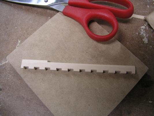
You might be right with the new blades but I would suggest a change to avoid pinching the cut off pieces between the blade and the guard. The best and safest option is to use a sled. That way everything moves through the cut. Everything can be held down. I constructed the following as an example: This is pretty easy to build but is very versatile. You can affix a spacing piece against the back block to get your repeatable width requirement. Mark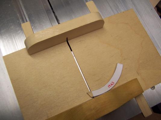
-
Steve, Currently my default is using the same stuff as on the Druid: General Finishes Gel Urethane. I definitely do need to commit sometime soon since after the rudder I will be applying the finish. No colored paint for this build. I am open to other suggestions....... On a side note it has been stated by my wife that there is really no place in the house for a ship this size. I have always said it is the journey and not the destination so that doesn't bother me right now. However, it looks like my older brother 'might' be getting engaged pretty soon. He has a whopper of a fireplace that is looking pretty lonely so this build might turn into a wedding gift. Might up the tempo and pace of the build..... Mark
- 128 replies
-
- 1
-
-
- artesania latina
- Finished
- (and 2 more)