

Jeronimo
-
Posts
729 -
Joined
-
Last visited
Reputation Activity
-

 Jeronimo reacted to Siggi52 in HMS Tiger 1747 by Siggi52 - 1:48 - 60 gun ship from NMM plans
Hello,
it is done, the port side is ready!
And I got a new toy, an LED ring lamp. She is good for working , and taking pictures through it. But that I think only at a short distance. You could dim in 10 stages and change the white temperature from cold, white to warm. And she is amazingly light.
-
Jeronimo reacted to Siggi52 in HMS Tiger 1747 by Siggi52 - 1:48 - 60 gun ship from NMM plans
Hello
and many thanks for your nice comments and likes. I'm overwhelmed 😮
I finished the fore mast port side and started with the main mast.
And that are the bolts who hold the chain plates in place. But today wasn't my day. So I stoped working. There where a 0,8mm bold should fit, I tried a 1mm bold and for the 1mm bold I drilled 0,8mm holes! And all ready with CA saturated 😬
-
Jeronimo reacted to Siggi52 in HMS Tiger 1747 by Siggi52 - 1:48 - 60 gun ship from NMM plans
Hello,
all the deadeyes and the first chainplates are installed. It takes so long, because the paint doesn't dry really good now.
Here are all parts together
And there some of them now
I did install also the chain-painter chain. What a funny name! I hope it will fit later with the anchor
And the whole ship. So for the next weeks I think, I'm busy to install the rest of them.
-
Jeronimo reacted to Siggi52 in HMS Tiger 1747 by Siggi52 - 1:48 - 60 gun ship from NMM plans
Hello, a short update
When I'm building the first deadeyes, I had only the pictures from the Centurion in my head 😐
They build the straps filled with tin! Over night I was thinking about this and thought that this is't right. So the next morning I changed it.
The „new“ deadeyes, above, look now much more correct. The one to the left are those for the fore mast, I build yesterday. Today I changed my strategy from soldering them, to glueing them. Here the first one for the mizzen mast. That is at least much easier 🙂
-
Jeronimo reacted to Siggi52 in HMS Tiger 1747 by Siggi52 - 1:48 - 60 gun ship from NMM plans
Hello,
today I finished the first deadeyes, or put them straps on. After clearing how to do it and wich dimensions and which material, it worked really fine. I forged the strap around the deadeyes flat, because the had a broad groove. These are 9 mm deadeyes, I got from Poland. Others I have from the US, and Canada. So they are really international. The copper wire is 1 mm in diameter.
And here the first test sitting
So, if you did't hear the next time anything from me, I'm busy with the rest of them 🙂
-
Jeronimo reacted to Siggi52 in HMS Tiger 1747 by Siggi52 - 1:48 - 60 gun ship from NMM plans
Hello
and thank you all for your nice comments and likes, they are very appreciated
today I installed the first parts to the fore and main channels. Don't ask me how there name is 😟 They are in the second row. Next, in the first row, the deadeyes are to be done.
-
Jeronimo reacted to Siggi52 in HMS Tiger 1747 by Siggi52 - 1:48 - 60 gun ship from NMM plans
Hello,
now this chapter is also finished. All channels are ready and installed. The next time the smith has to build in the deadeyes.
-
Jeronimo reacted to Siggi52 in HMS Tiger 1747 by Siggi52 - 1:48 - 60 gun ship from NMM plans
Hello and thank you for your likes,
during the paint at the billboard dried, I made the ropes for the gun port lids. And because I had the ropewalk set up, I made also the ropes for the gammoning. Here I tried also same splices en miniature. The right one was the first, but the second is, I think ok.
And here the first windows. The smaller ones I have to rebuild, because they separated when I tried to cut them to the right size. The larger one, for the captains gun port, did it well. The only thing is, that the glue made the acrylic glas blind. I don't really know what to do with them. I glued the wood to the acrylic glas with the glue for acrylic, but that solved also the paint from the frames ☹️
-
Jeronimo reacted to Trussben in HMS Pegasus 1776 by Trussben - 1:48 - Swan-class sloop based on TFFM
Work on Pegasus starts again.
First on the list was to tie the upper deck into the wing transom.
-
-
Jeronimo reacted to Gaetan Bordeleau in 74-gun ship by Gaetan Bordeleau - 1:24
Here is an example why it can be interesting to build at a larger scale:
When the anchor is lift on the ship there is a cable which is part of the cathead, the name is bosse de bout. This cable probably slip on an arched wood part named skate of the bosse de bout. It is also probably turned around the railing ounce or two and may be by having this skid, it slides easier? To know a clear answer, more research is needed or may be someone knows how.
-
 Jeronimo got a reaction from ccoyle in French 18-pdr Naval Cannon 1779 by Jeronimo - FINISHED
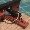
74 GunShip
New - and Reconstruction of the section of the second gun deck.
The cannon stayed the same, only the locking of the cannon barrel / mount (Lafette) was changed.
Karl
(Google Translator)
-
 Jeronimo got a reaction from Dziadeczek in French 18-pdr Naval Cannon 1779 by Jeronimo - FINISHED
74 GunShip
New - and Reconstruction of the section of the second gun deck.
The cannon stayed the same, only the locking of the cannon barrel / mount (Lafette) was changed.
Karl
(Google Translator)
-
 Jeronimo got a reaction from BenD in French 18-pdr Naval Cannon 1779 by Jeronimo - FINISHED
74 GunShip
New - and Reconstruction of the section of the second gun deck.
The cannon stayed the same, only the locking of the cannon barrel / mount (Lafette) was changed.
Karl
(Google Translator)
-

 Jeronimo got a reaction from yvesvidal in French 18-pdr Naval Cannon 1779 by Jeronimo - FINISHED
74 GunShip
New - and Reconstruction of the section of the second gun deck.
The cannon stayed the same, only the locking of the cannon barrel / mount (Lafette) was changed.
Karl
(Google Translator)
-
 Jeronimo got a reaction from Bitao in French 18-pdr Naval Cannon 1779 by Jeronimo - FINISHED
74 GunShip
New - and Reconstruction of the section of the second gun deck.
The cannon stayed the same, only the locking of the cannon barrel / mount (Lafette) was changed.
Karl
(Google Translator)
-
 Jeronimo got a reaction from tlevine in French 18-pdr Naval Cannon 1779 by Jeronimo - FINISHED
74 GunShip
New - and Reconstruction of the section of the second gun deck.
The cannon stayed the same, only the locking of the cannon barrel / mount (Lafette) was changed.
Karl
(Google Translator)
-
 Jeronimo got a reaction from Ainars Apalais in French 18-pdr Naval Cannon 1779 by Jeronimo - FINISHED
74 GunShip
New - and Reconstruction of the section of the second gun deck.
The cannon stayed the same, only the locking of the cannon barrel / mount (Lafette) was changed.
Karl
(Google Translator)
-
 Jeronimo got a reaction from GrandpaPhil in French 18-pdr Naval Cannon 1779 by Jeronimo - FINISHED
74 GunShip
New - and Reconstruction of the section of the second gun deck.
The cannon stayed the same, only the locking of the cannon barrel / mount (Lafette) was changed.
Karl
(Google Translator)
-
 Jeronimo got a reaction from bruce d in French 18-pdr Naval Cannon 1779 by Jeronimo - FINISHED
74 GunShip
New - and Reconstruction of the section of the second gun deck.
The cannon stayed the same, only the locking of the cannon barrel / mount (Lafette) was changed.
Karl
(Google Translator)
-
 Jeronimo got a reaction from G.L. in French 18-pdr Naval Cannon 1779 by Jeronimo - FINISHED
74 GunShip
New - and Reconstruction of the section of the second gun deck.
The cannon stayed the same, only the locking of the cannon barrel / mount (Lafette) was changed.
Karl
(Google Translator)
-
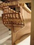
Jeronimo reacted to Gaetan Bordeleau in 74-gun ship by Gaetan Bordeleau - 1:24
I glued the parts and there are still a few parts to be done.
-
Jeronimo reacted to Gaetan Bordeleau in 74-gun ship by Gaetan Bordeleau - 1:24
Stair railing during construction on the forecastle.
What is the worst way to build the stairways? Glue the parts as they are done. Parts will be glued faster on the model but it will be harder to build other parts on the model itself. At the opposite, it is easier to build as much as possible without gluing. This way, a part can be remove as needed to be shape.
Often, it will be easier to shape a part on the vise, simply because the vise will easily hold the part, something that the fingers cannot do very well, and the hands will be free to hold the tool to shape the part:
at the good working angle and at the good height. Not in all the situations, but often a part of the fabrication is much easier done if the tool meets the part at the good angle and also at the good height where it is easier to perform a movement.
2 things are needed to achieve this: an electric height adjusting table. This is 1 of 2 important tools that everybody should have when possible. The other one is a vise. Choosing a vise looks like to be very easy to do.. This subject comes back occasionally in the tool section. The newcomer will usually buy a vise at a very low price.
As in the learning of the model ship building, understanding what is a good tool often needs experimentation. When I was a beginner, I bought a hobby vise. With the wearing, the vise became harder and harder to squeeze tight the jaws. Also the angle adjustment had more and more trouble to hold the working position. It was not long that this tool became unusable.
The second category of vise would be in the metal machining category. There is a company who made a good little one and this is Unimat. The problem with the milling vise, is that it is difficult to find a quality vise in the small sizes
Finally, a third category of vise comes from the jewelry tool industry. The range is quite large. Unfortunately, there is a bad side, the price. In this category, the price can be as low as$20 for something simple and close to $1000 for an elaborate one.
One of the main problem of the vise is to hold a part parallel to the table. The part has a tendency to be pushed out vertically, out of the vise. This is why a machinist will give the part a light hammer blow to seat well the part on the vise. This is also why the jaws need to have a way to stay well seated on the vise base.
There are a lot of vises on the market but very few can really be called a good vise!
-
-