catopower
-
Posts
1,900 -
Joined
-
Last visited
Content Type
Profiles
Forums
Gallery
Events
Everything posted by catopower
-
 Hello Ab, Thank you for the advice. I will consider changing the topsail later. I may save these suggestion for a future model of the Mary, as I have my own un-started kit in storage. If I build another, I will remember to alter the mast so that the sheave for the topsail halliard is higher, and modify the topsail itself so that foot arcs up higher to clear the jib. Also, might lower place the tackle for the jib halliard a tad lower on the mast.
- 82 replies
-
- 4
-

-
- Yacht Mary
- Mamoli
- (and 1 more)
-
Thank you for the comments Ab. The mast was already constructed by the original builder, and I chose to keep as much of his work as possible. But, even so, I'm afraid I don't have much general knowledge of Dutch shipbuilding, and the it plans, as you may already guess, are somewhat lacking in the accuracy of these details. I did make some modifications to the rigging, which was based, in part, on your models. If I build another similar model of the Mary or similar, I will remember your comments about the location of sheave of the topsail halliard. I didn't know about the iron brace. After this weekend, perhaps I'll go back and see if I can add it to the model "after the fact". Another issue I noticed when I started adding the topsail is that the spreader yard seems a bit too long and heavy. If I were to do this model again, I would consider correcting that as well.
- 82 replies
-
- 2
-
-
- Yacht Mary
- Mamoli
- (and 1 more)
-
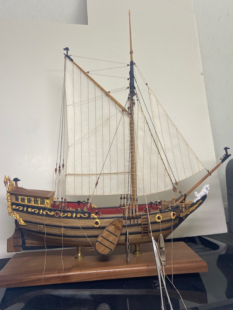
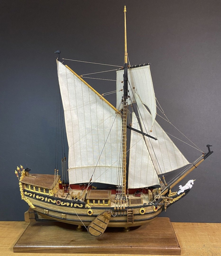
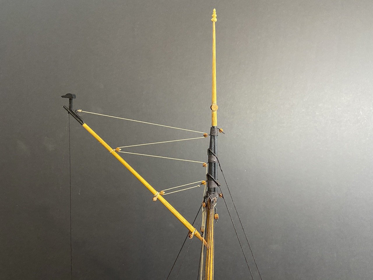
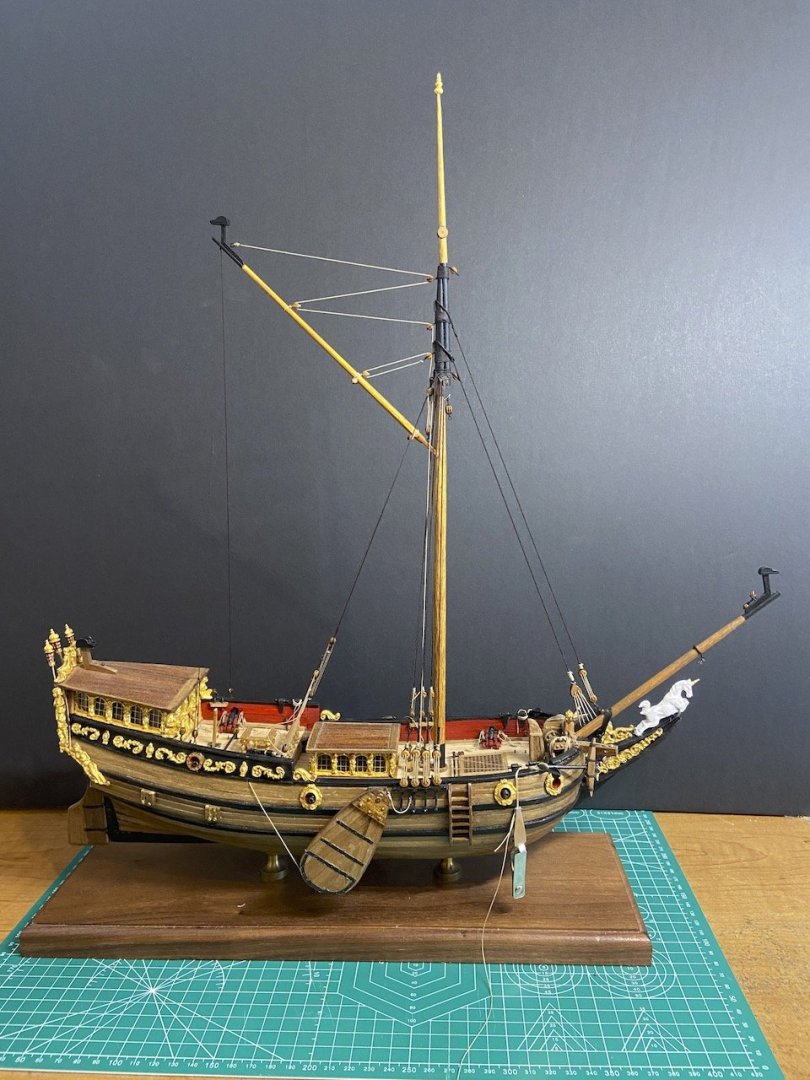
Yesterday, I had the day off, so I took the opportunity to add the topsail and finish tying off all the running rigging. I ended up having to belay a lot of the lines incorrectly, but you can't tell in most cases. In other cases, I figure that I'll be adding rope coils at a later date to hide some of those details. Flags are yet to go on, but I'm no longer feeling pressed for time to get the model done for the IPMS show this weekend. And, in any case, I should have time to get the flags done by tomorrow. Would like to have braced the topsail around more, but the spreader yard was starting to hit the port shrouds and I din't want to deform them. Also, not sure what others do about this, but that spreader yard has no lines that pull down on it. On most ships, you at least have the sheet lines, which can be rigged to apply some downward pressure. As a result, the spreader yard halliard was too slack. So, I cheated, and if you look really closely, there's a thin black thread pulling the yard down, tied off to the staysail sheet horse. It's hardly noticeable, and it works! Anyway, flags are next...
- 82 replies
-
- 10
-
-
- Yacht Mary
- Mamoli
- (and 1 more)
-
Thanks Julian, I appreciate your comments. I have to admit that as much trouble as I've had in the past with uneven bulkheads and such, the Mamoli kits can look really nice when completed. It always surprises me when I see a completed Mamoli kit. A friend of mine just built Mamoli's HMS Victory and now working on Mamoli's Royal Louis, looks really nice, and makes me want to build one. I actually have a partially built Victory that someone was giving away as he was leaving the hobby. Nobody else wanted his stuff, so I took all of his stuff to store. I managed to find homes for all of his stuff except this HMS Victory model. I'm thinking maybe I'll try to pick up where he left off. That seems to be a thing with me these days!
- 82 replies
-
- 3
-
-
- Yacht Mary
- Mamoli
- (and 1 more)
-
I kind of wondered the same thing. Amati even has a large range of America's Cup yachts, and 3 kits of the Endeavour in two different scales and construction styles. But, all the bigger manufacturers tend to make their own versions of what they think is a popular subject.
-
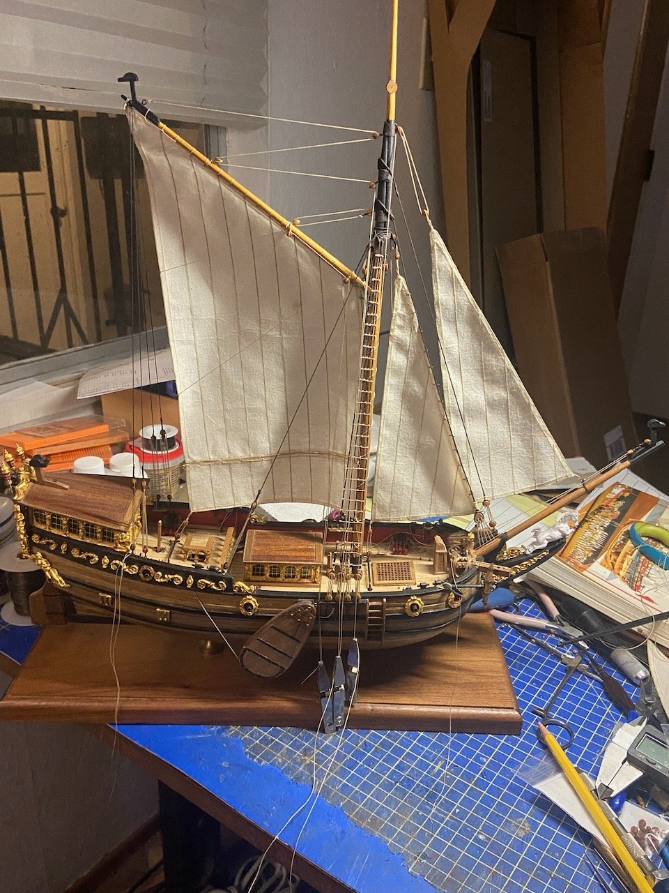
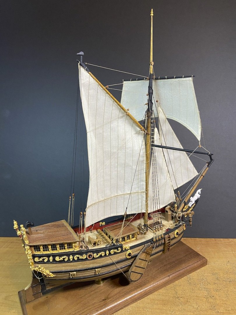
Thank you Druxey, Baker. I made some adjustments and I'm MUCH happier with the mainsail. Also, I realized that the lighting in the last photo is what main the staysail halliard look too big. Here's an updated photo. Still have to secure the lines. Then I can add the square topsail and finish up the flags.

- 82 replies
-
- 9
-
-

-
- Yacht Mary
- Mamoli
- (and 1 more)
-
Thank you Druxey and Baker for the sentiments on Ken. I've been recently realizing that his loss may also have a profound impact on the activity of the South Bay Model Shipwrights club, of which Ken was Vice President for as long as I can remember. He also wrote up the club newsletter, The Foghorn, and now I find I have nobody in the club that I can really discuss ship model industry news, and historical aspects of ship modeling with. Anyway, thanks too to you both and Gregory for your comments on this model. Sails are going on now. I've pulled the gaff off the model to add the mainsail. It's back on now, and I'm adjusting and belaying lines. Not LOVING the sails, but they're okay. Looking at this pic, I think the jib halliard is too thick. Not sure why. It's not difficult to replace that line. Don't know that I like the set of the mainsail either, but there are a lot of lines affecting the angle of the gaff. I want a slightly steeper angle on the gaff and haven't quite figured out what lines are keeping me from getting it. Might be the throat halliard... Anyway, it'll probably all be fine by the time I'm done. Should be another week. I did a lot of work on it yesterday. Taking the day off from it today and will try to make a big push on Monday.

- 82 replies
-
- 9
-
-
- Yacht Mary
- Mamoli
- (and 1 more)
-
Hi Al, I like the bulwarks planking jig. I've done something similar myself. On the timber head strips, are they plywood? I can imagine myself breaking off timber heads, trying to sand the bottom edge if they're not.
-
Slow going, but still progressing. I had to deal with jury duty this week, plus trying to deal with some work related bureaucratic junk. But, the worst thing was losing another ship modeling friend, just about three weeks ago. Just saw the guys two days before he died at a local ship model meeting. His name was Ken Lum, an NRG member. He was a great guy at the meetings. Hadn't built a ship model in, I don't know, 20 years or more. But, he was always very up to date on the ship modeling hobby news, and knew something about EVERYTHING, so he was always a big part of any historical or ship model discussion. I'll miss him very much for quite some time I think. As for the yacht Mary, work continues. I finally finished making the sails, including the bonnet on the mainsail. Some blocks have been added, bowlines, etc. Sewing machine is now put away, and I'm ready to rig. I've got some sheet blocks to add to the staysail and the mainsail, then I'll bend the mainsail. In the meantime, one thing confuses me a bit. I know the Mamoli/Dusek plans call for parrals to be added to the main gaff jaws, but I don't see any on the photos of the Utrecht replica that Baker posted (post #17), nor do I see any on Ab Hoving's English royal yacht model. Is this something the Dutch didn't bother with on such a small vessel? Like omitting ratlines as they were unnecessary? And, before I add the sails, I'm now thinking again about reef points. The Utrecht replica has them on the mainsail. But, as Druxey pointed out, they don't seem to appear in paintings of the period. I'll give it some more thought, but still leaning towards leaving them off.
- 82 replies
-
- 5
-
-
- Yacht Mary
- Mamoli
- (and 1 more)
-
Hi Druxey, I'm actually figuring on trying that on my HMS Wolf build, which I want to get back to soon. I want to try some furled sails and figure it will also be easier to do with silkspan. Also, the smaller scale of that model really calls for it (1/72). For the Mary, in part, I wanted to build it the way I think the original builder would have done, though I have no actual evidence that he would have even added sails or what type. It's just more of a judgement from the "feel" of his building style. Even the way I'm making the sails now doesn't seem quite right for his model. But, I needed to satisfy myself too. These cloth sails are somewhere in between.
- 82 replies
-
- 4
-
-
- Yacht Mary
- Mamoli
- (and 1 more)
-
Thank you for the comments, Ab! While the Mary was Dutch built, I assume it ended up operated by English sailors, with an English captain. So, I wonder if some changes were made to her at some point to accommodate English practices. I have considered both rig possibilities, but I'm too chicken to declare the rig to be one way or the other, so my model will end up somewhere in between. Probably, this will cause it to have a rig that was never correct. But, at least I'm learning (I think).
- 82 replies
-
- 3
-
-
- Yacht Mary
- Mamoli
- (and 1 more)
-
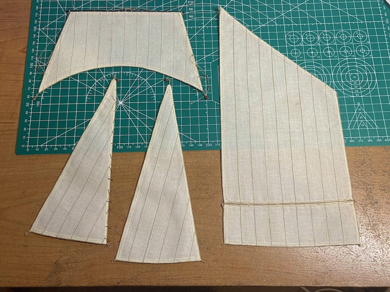
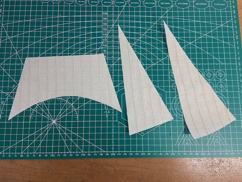
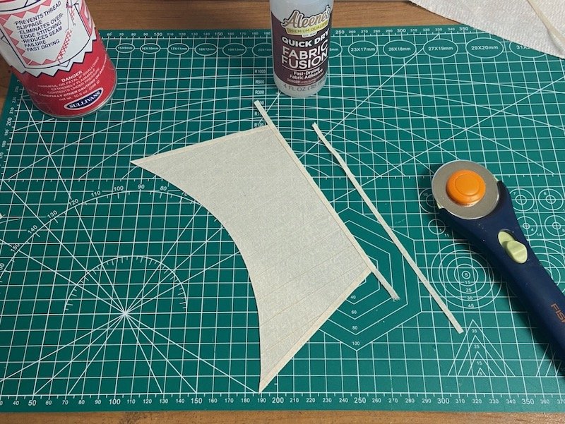
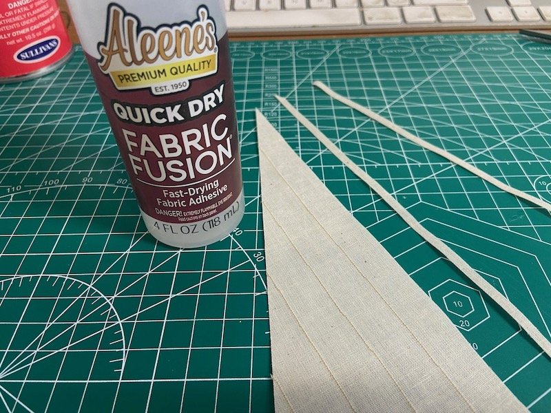
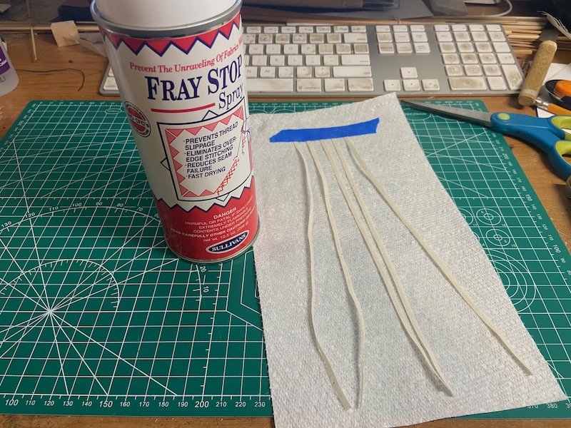
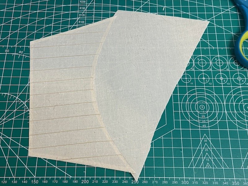
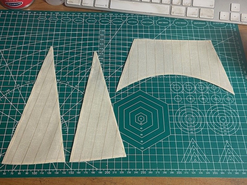
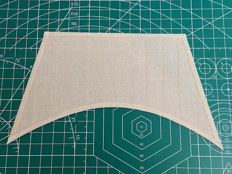
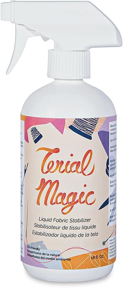
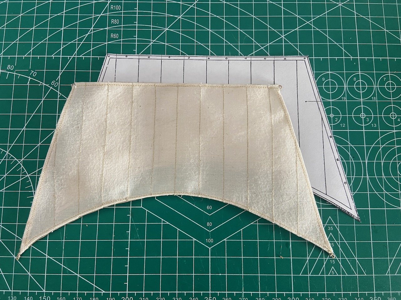
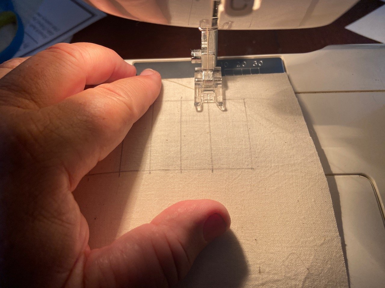
Not much to actually report, except that I've been trying to get these sails done for a couple weeks, and since I switched my sail making technique, I managed to make good progress over two days. I probably mentioned this before, but I'm using unbleached cotton muslin. This was hand washed and then treated with a fabric stabilizer called Terial Magic. This has to soak in for 15 minutes, wrung out, then the material is ironed. The resultant material acts like paper. The stabilizer can be left in or washed out later. Topsail and head sails were initially sewn and cut to shape. I cut some strips of fabric and sprayed them with Fray Stop, which is like the fabric stabilizer, but it doesn't wash out. It smells a lot like lacquer(!). I'm doing this, because I think I'm going to wash the Terial Magic out of the sails later (maybe), and I'm a little concerned that later the edges of these strips might start to fray. I'm gluing the strips using Aleene's Fabric Fusion, which is a clear, permanent fabric glue. I've never used it before. It's possible that my using the Fray Stop may keep the fabric glue from sticking as well. Not really sure about that. I didn't really consider that when I cut and sprayed those strips. We'll just have to see how it goes. I glued the strips into place using Aleene's Fabric Fusion. I'm showing a rotary cutter in the photo below, but I actually ended up using a scalpel with a fresh blade for more of the cutting. The rotary cutter might have worked better if the blade was newer. It was fine really, but the fresh scalpel blade was better. That curved edge of the topsail was the biggest challenge. I matched the cure as best I could in a larger piece of cloth, then glued the whole cloth to the sail. I then just cut the excess away. All tablings glued into place. I considered just leaving the sails in this state, but I wanted to show stitching of the tablings. I also thought that the tablings might hold up better if I end up washing them after I sew them. Finally, here are the first three sails. Just the mainsail to go. The tablings are all secured with one line of machine stitching. That part turned out okay, certainly a lot better than my earlier attempt. I still need to add the bolt ropes. I'm not too worried about that part. I'm just gluing them into place. But, I'll probably add the bolt ropes to these three sails before I make the last sail.
- 82 replies
-
- 7
-
-
-
- Yacht Mary
- Mamoli
- (and 1 more)
-
After making the head sails and the topsail, I can honestly say that I hate how these are turning out. I can sew just fine, but the tablings are too bulky, and they're ruining the appearance of the whole thing. It's hard to get the corners done nicely, and all. I think I'm going back to making the sails in the way that I can do best, which is making them almost the same way others make paper sails. I think the process will also go much faster, which is a good thing, because I'm getting tired of remaking sails. The topsail isn't great, but it's actually okay. Still, if I'm going to change the way I make one sail, I have to change them all. I'd just love to be able to move on. Unfortunately, I probably won't have time to do much until closer to the weekend. But, on the positive side, there are only four sails to make, so we'll see.
- 82 replies
-
- 5
-
-

-
- Yacht Mary
- Mamoli
- (and 1 more)
-
Baker, sorry I didn't reply to your flag printing suggestion before. I think I'm happy enough with the double-sided, plain paper flags, but I may give your idea a try, just to see how it works out. And maybe it will be useful in a future build. Thanks!
- 82 replies
-
- 2
-

-
-
- Yacht Mary
- Mamoli
- (and 1 more)
-
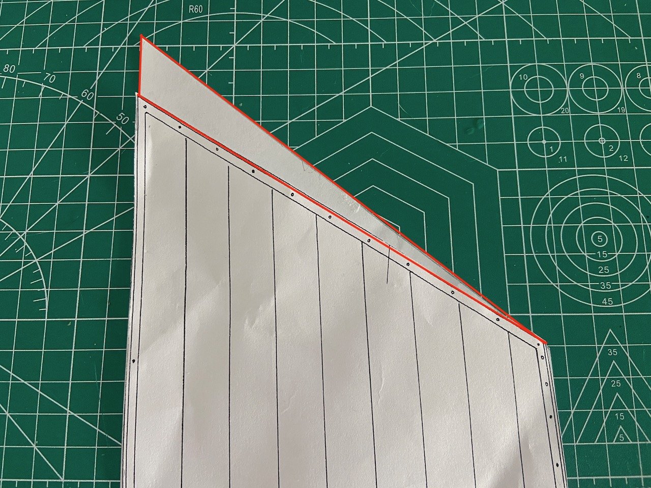
The shrouds are now "rattled down". I didn't get too fancy and just did my usual clove hitches all the way across. It's the way I've always rigged the shrouds, but in the future, I think I will try using cow hitches at the ends as someone suggested. I can see where this could actually make the ratlines easier to do, as well as make them more secure. It's not easy to trim those end knots and for them to stay secure. So, I gave them a strong dose of PVA to hold them. Not perfect, but it's done! I redid a few of the ratlines where I needed to do some adjustments and had a few knot failures. But, it's all secure now. Also, the photo is before I added one more ratline at the bottom end. By the way, for the fun of it, I decided to record myself tying ratlines, and I posted the video on Facebook and Youtube. Nothing fancy, just video... But now, I'm dealing with the sails. My sails usually turn out fine, but I'm never happy with the process. I've done other sails on other models and used fabric stiffners and glued all the tablings and reinforcements, and I'm very happy with how those turned out. In the future, I'll be trying out making silkspan sails. But for this model at this scale, I wanted to follow a more "traditional" process, where I sew all the tablings, and that's slowed me down a lot, mostly because I'm thinking about things too much. The first sail completed with a glued-on boltrope is the topsail. Folding over the fabric at the foot was sure a pain. I wasn't able to do a double fold, so it's not as sharp on the back side as I'd like. And, oops, somehow I managed not to take a photo of that side... 😬 The main issue I have is, of course, the mainsail. I'm not done with it yet, and thinking maybe I'll just get the jib and staysail done first, since they're pretty straight forward. But, here's the first issue with the mainsail... I've constructed my model with higher peak, so I can't use the kit pattern as is. I cut a new pattern with the added area highlighted in red, above. Now, I guess I'd better be off to start working on these remaining sails. Still not sure about the bonnet and reef points, so maybe I will just start with those head sails...

- 82 replies
-
- 5
-
-
- Yacht Mary
- Mamoli
- (and 1 more)
-
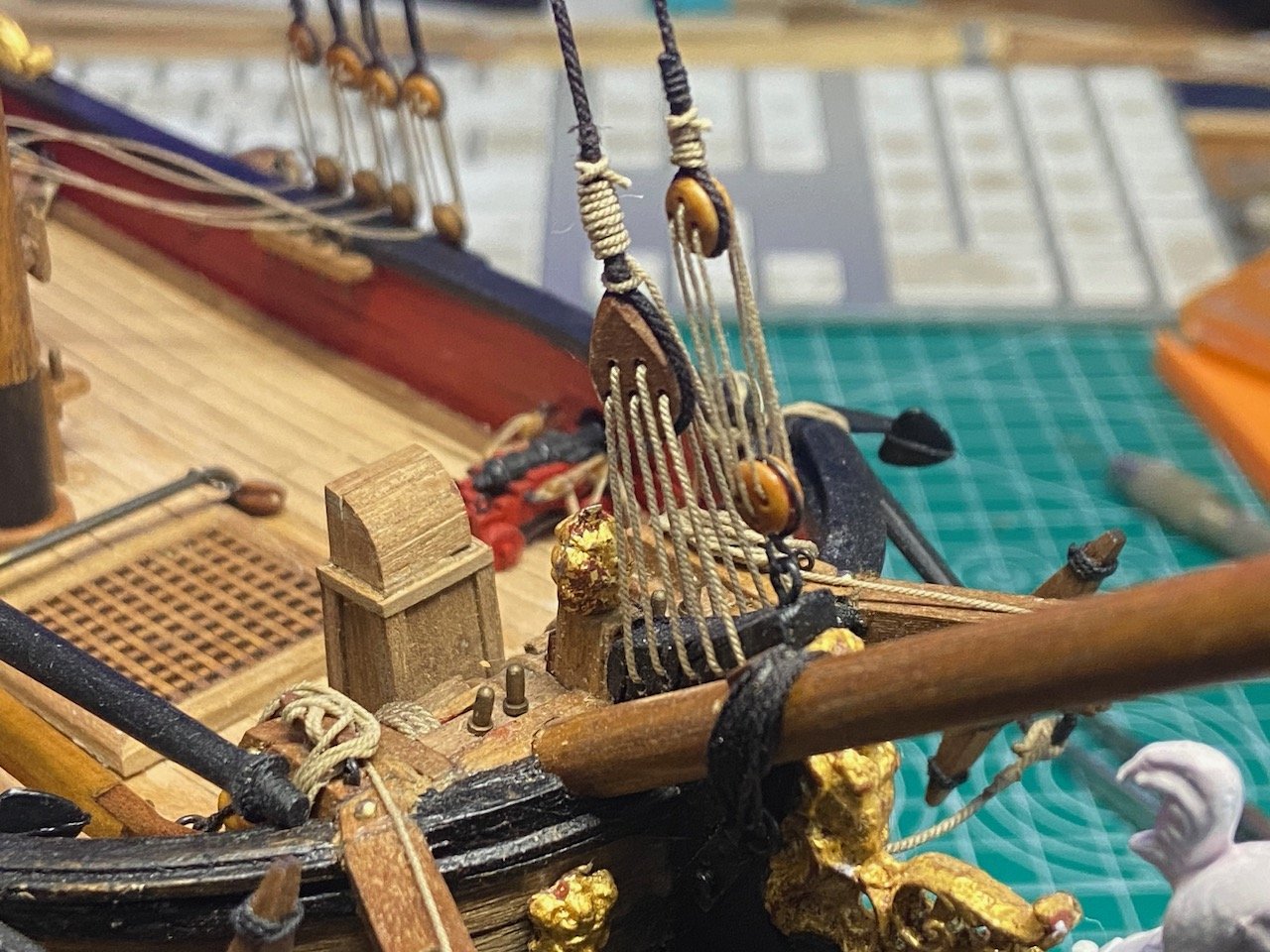
As I recall, the instructions for these Constructo kits are printed on the box.
-
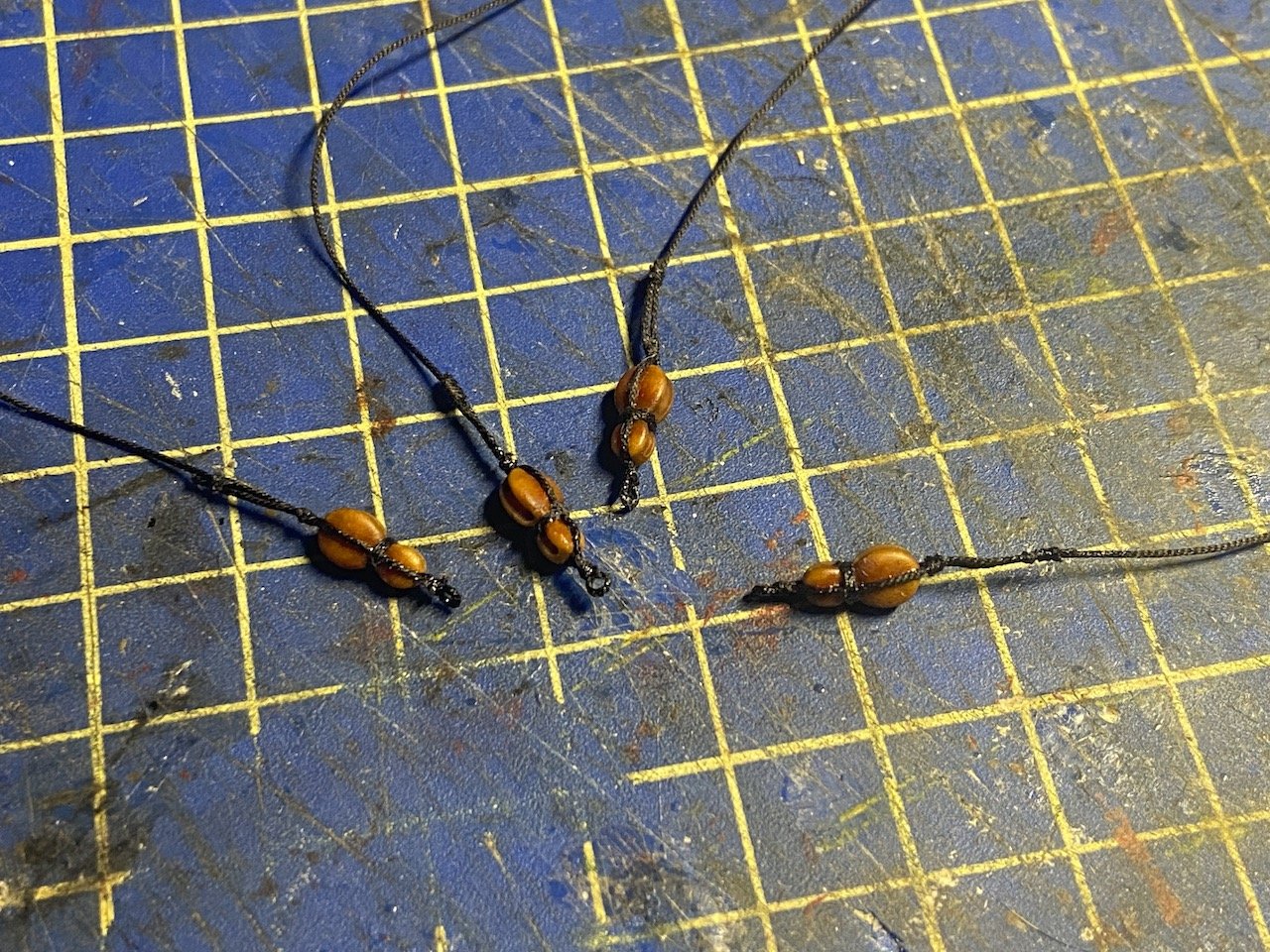
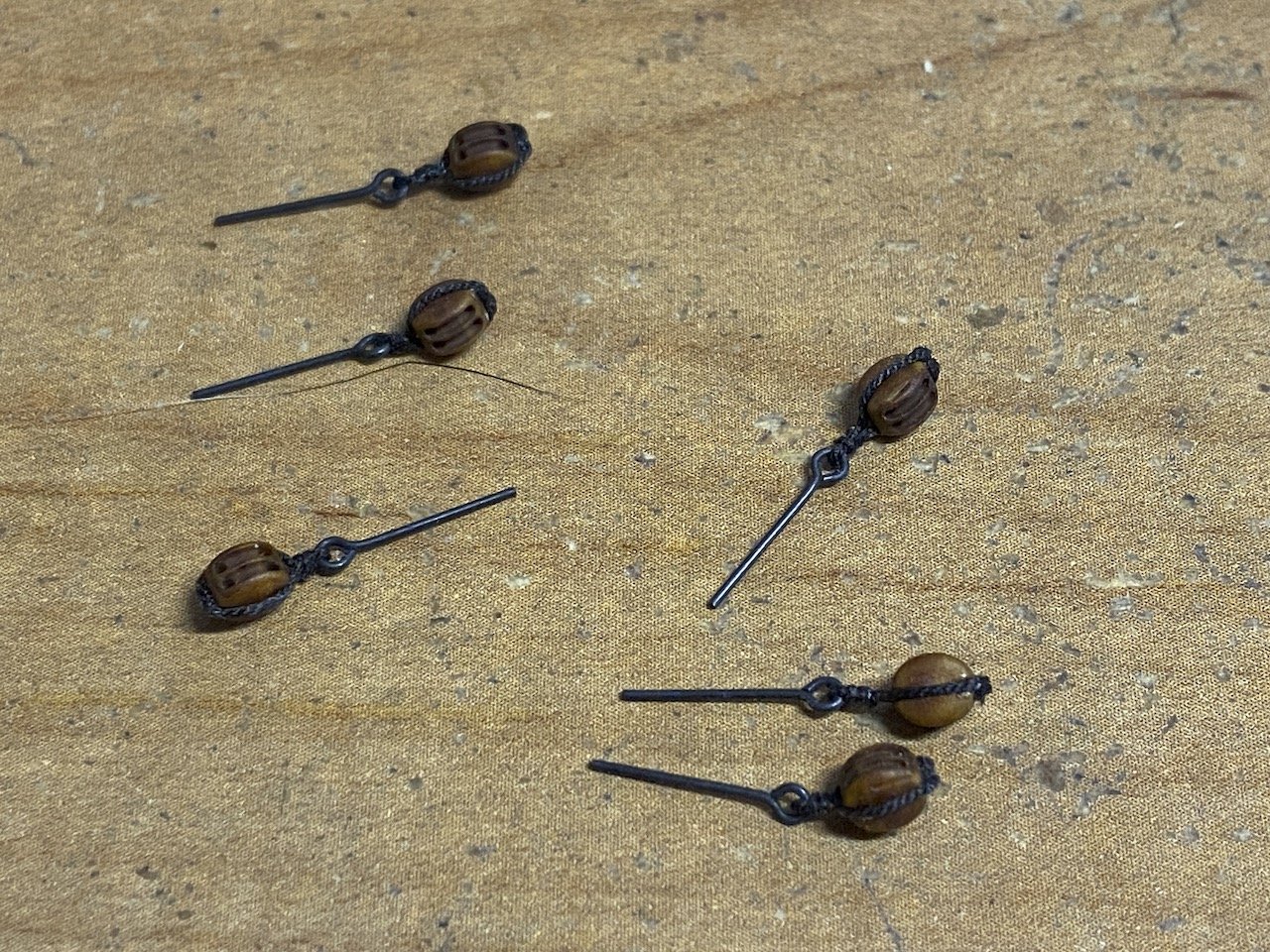
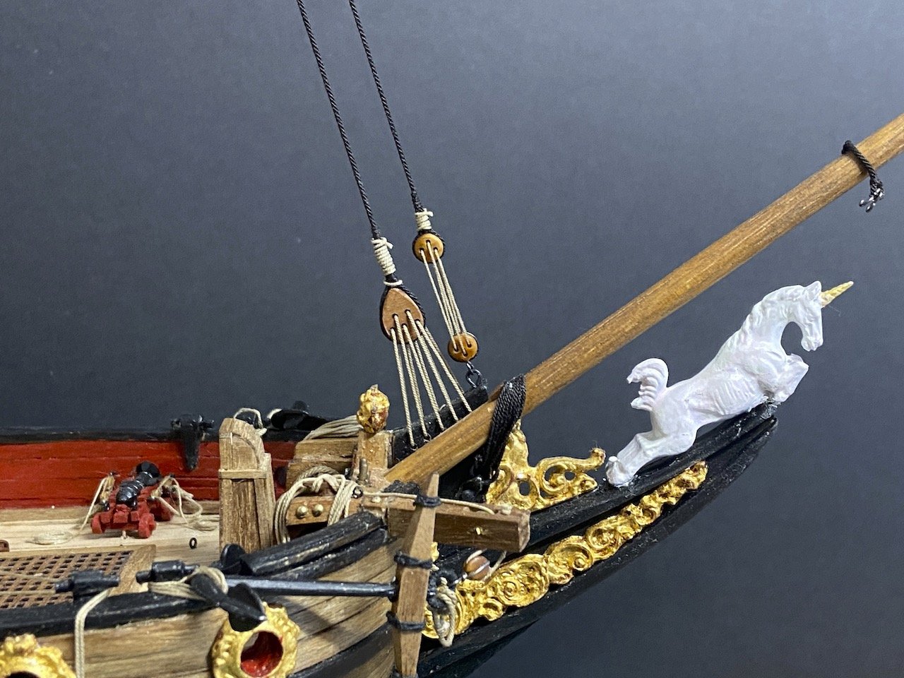
Forward, Back, Cha Cha Cha... That's the kind of dance it's been the past couple days on this project. I made the standing portion of the vangs. Are these pendants? Anyway, made all four of them with 8mm fiddle blocks stropped in their ends. Then, I realized that I didn't rig them with beckets. Had to redo all four... 😖 Today, I fixed the issue, cut away the temporary line I had in place of the vangs, and rigged the vangs. All looks good. They're not permanently in place, since I may have to remove the gaff when I rig the sails. During this last step, the stropping of one of the double blocks (the very last one I was working with, of course) gave way, so I had to remove the eyebolt for that block. It didn't want to come out, but finally did. I destroyed the eyebolt in the process, so had to replace it and re-strop the block to it before finishing up... three-four... cha cha cha... Now, I'm all set to get to work on the sails. They're basically cut and ready to finish up. More on that next time.
- 82 replies
-
- 5
-
-
-
- Yacht Mary
- Mamoli
- (and 1 more)
-
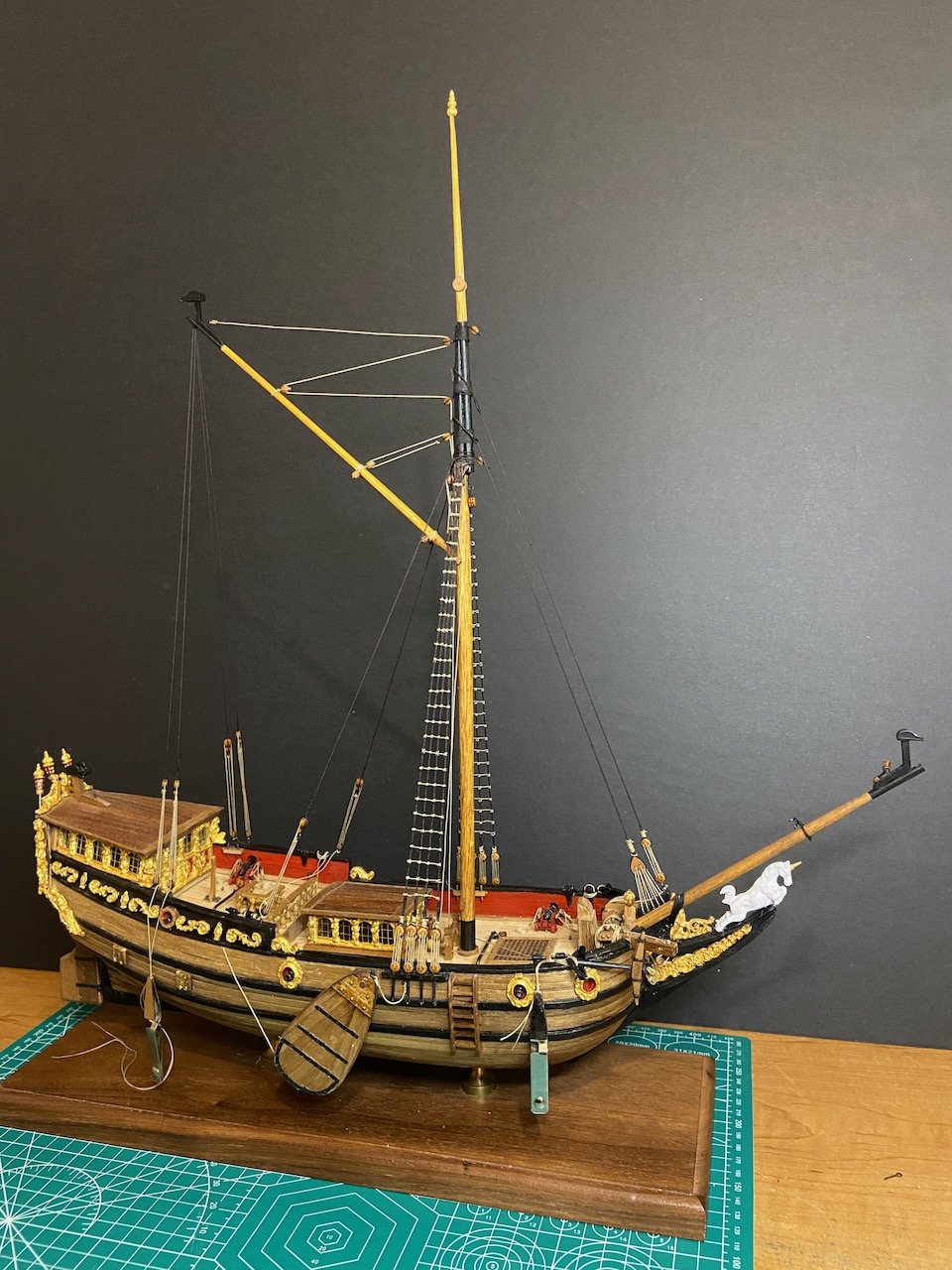
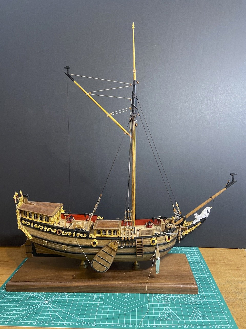
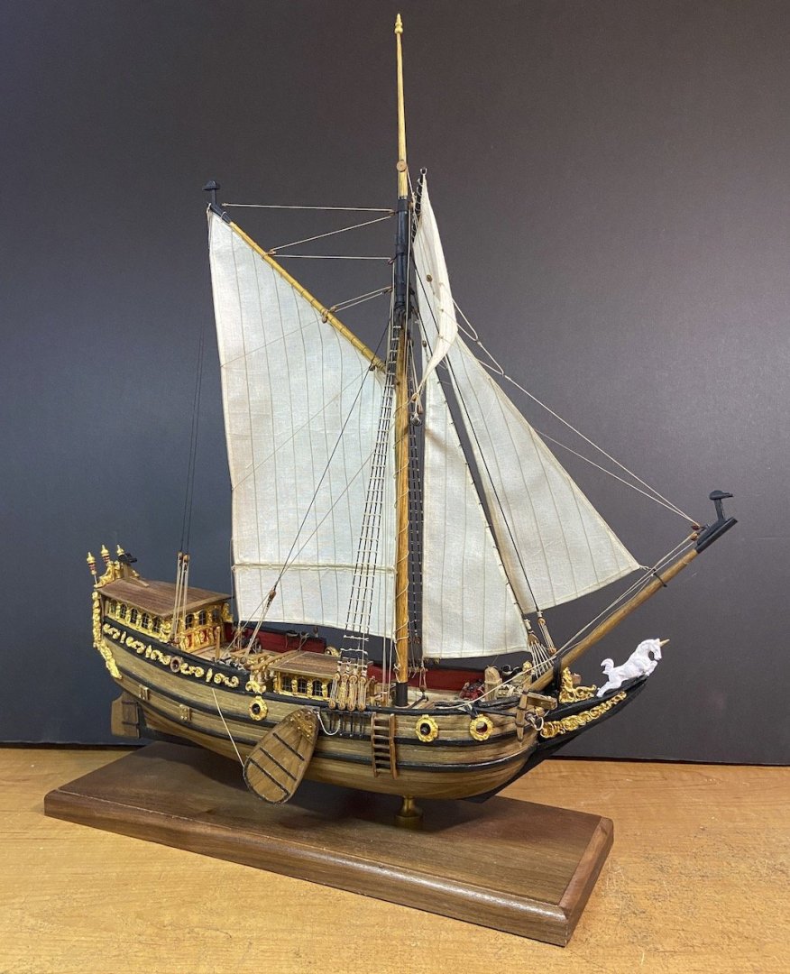
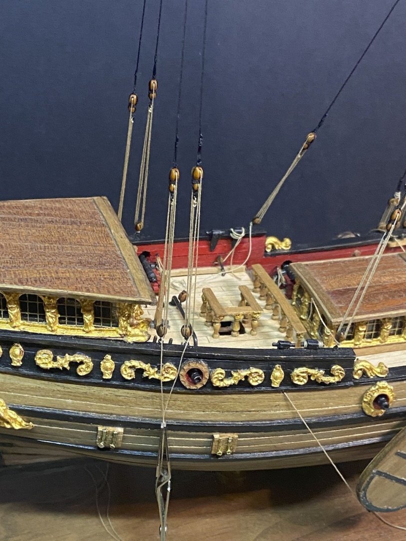
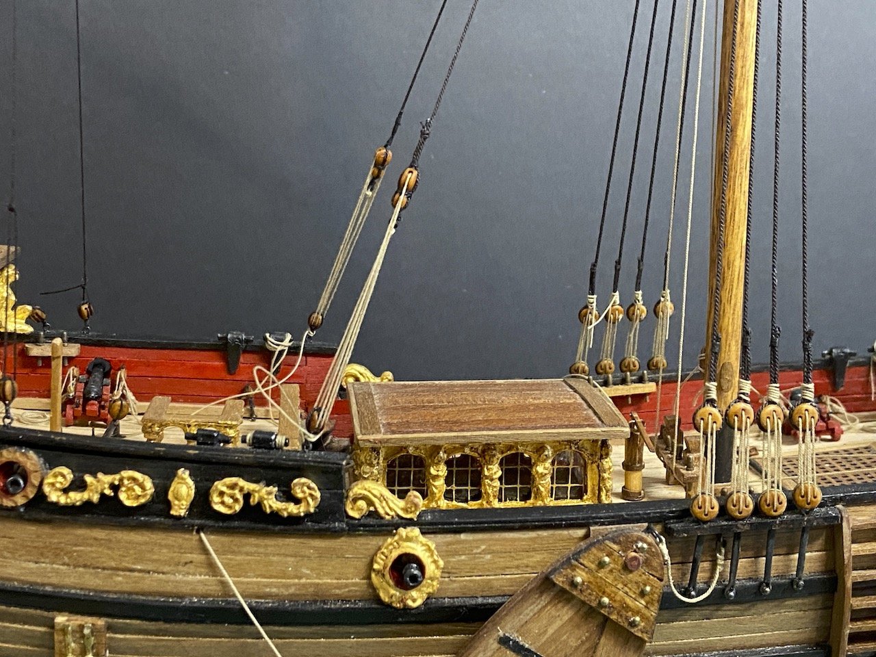
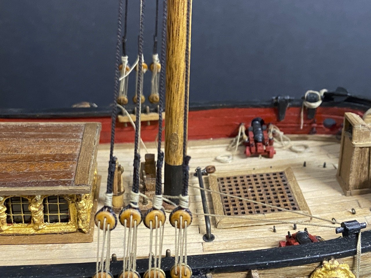
Flag work aside, and with all the main detail work done, I finally made some progress on rigging.

- 82 replies
-
- 10
-
-
-
- Yacht Mary
- Mamoli
- (and 1 more)
-
In my own experience, contact cement has worked fine for attaching wood veneer planking, and I think it will continue to do so. If working with thicker planking, I would use PVA and a little CA glue. But, there is very little hold necessary for veneer planking. It's not like a countertop or shoe that has to stand up to decades of abuse. Never seen contact cement bond fail. But, that's just me.
-
Hi Gregory, for the folds, it's hard for me to describe. It's basically a matter of holding the mounting edge tight, while pulling down on the top edge of the flag. I start closest to the mounting edge. I guess the trick is to fold back and forth, just keeping in mind how gravity keeps pulling down on it, while the wind is trying to push out on it. Because it's plain paper, it keeps its shape pretty well. I haven't decided yet just how windy the conditions are for the ship! On the tissue paper, yes, I taped it to a plain sheet. Did that a couple times. The way my printer, a Canon IX6820, feeds, it doesn't feed it evenly, and I end up with a crumpled mess. I might try again in the future, but for now I'm pretty happy the way the single-thickness plain paper is turning out.
- 82 replies
-
- 3
-
-
- Yacht Mary
- Mamoli
- (and 1 more)
-
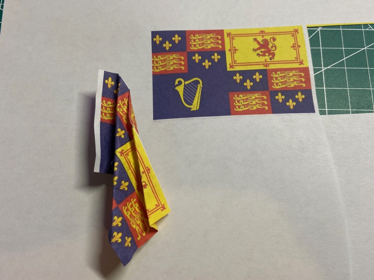
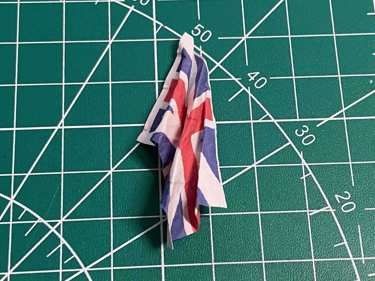
Made my first attempt at printing flags on tissue paper and couldn't get the paper to not jam up in the printer ☹️ I was able to print on regular paper and thought about folding them over, but I know how thick that ends up. Decided to see how good the alignment consistency is on my printer. Turns out, if I'm careful and have the images perfectly centered, I can print one side, flip the paper over, and print on the other, and it's pretty darned close. I have three usable flags done this way now, and just the pendant left. I don't have any artwork for that flag, so I'll have to draw it up from scratch. Pretty basic, so it shouldn't take that long to do. I only folded the flag above. I didn't try to wet it at all. I'm not sure of the colorfastness of this ink. I'm using some cheap third-party ink, so I think I have to spray this with something to keep the colors from running. But, I'm not sure if that's just going to make the whole flag itself waterproof, and prevent me from using water to shape it. It probably doesn't matter, as I think the flags will shape nicely, even without wetting them. The one thing I forgot about is the white edge of the paper. It's just like paper modeling, one needs to color the edge to take off the bright white color. Note that I tried to give the above flag some texture, but I made it a bit too wrinkly. I'll keep that in mind for the final flags.
- 82 replies
-
- 9
-
-
- Yacht Mary
- Mamoli
- (and 1 more)
-
Hi Patrick, thanks for the link! That's exactly what I've been thinking of doing. I hope I can get my flags to look as nice as yours!
- 82 replies
-
- 3
-
-
-
- Yacht Mary
- Mamoli
- (and 1 more)
-
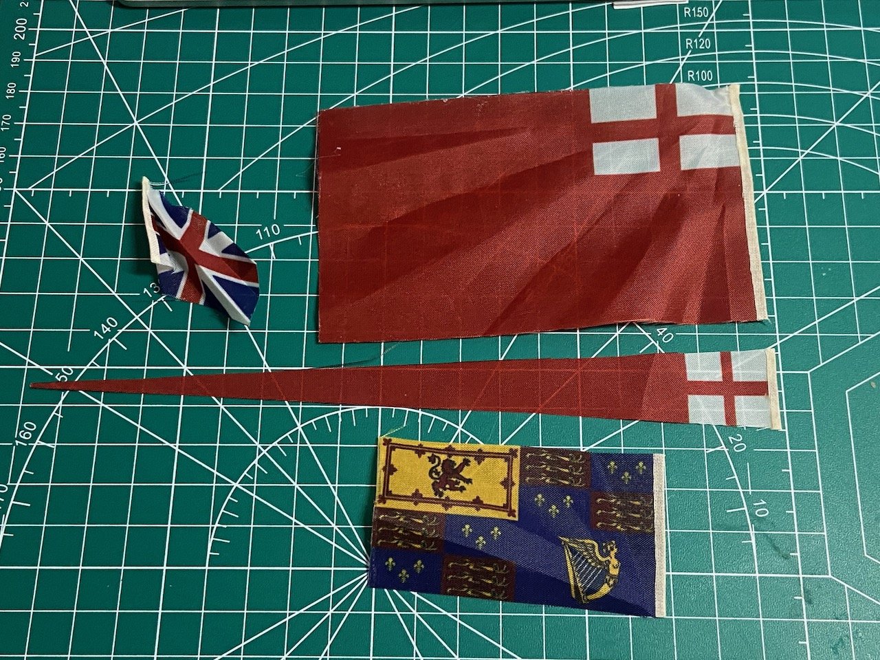
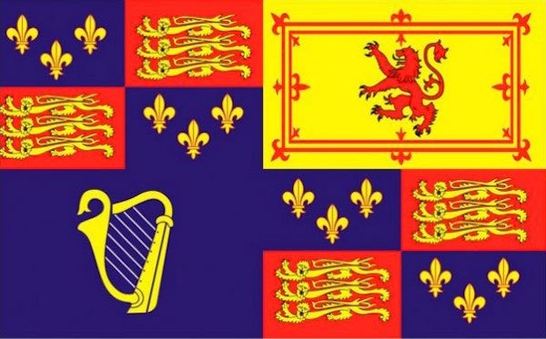
Didn't get any feedback on my questions from my last post, but I'm moving on now. Looking at the flags in this Mamoli/Dusek kit. They appear to be printed nylon. They're not really dissimilar from the flags in the Woody Joe Charles Royal Yacht kit, but those flags could be shaped quite nicely. These don't seem to hold my attempts at shaping. I've found what I think is appropriate artwork on the Internet, so I'm considering printing the flags on my color inkjet printer. I think I want to print both sides of the flag and fold over and glue. I'm considering trying to print on silkspan if I can get that to work. Any suggestions on how to do that successfully? I just don't want them to be look too thick. I just noticed that the first flag is truncated slightly on the left side. I think I can fix that without too much trouble. Alternatively, anyone know of a source for the needed flags?


- 82 replies
-
- 5
-
-
- Yacht Mary
- Mamoli
- (and 1 more)
-
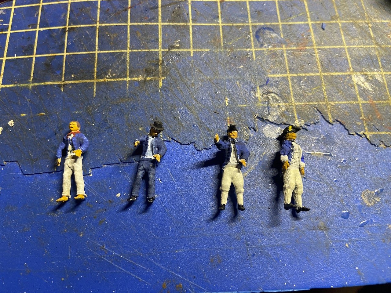
Still working on finishing up my "inherited" Yacht Mary build. It's actually been nice working on wooden ship models for a bit. I'm now waiting for an order I place with Syren Ship Model Company, so I thought I'd pick up a little side task that's related to this HMS Wolf build. Specifically, I've been playing around with my AnyCubic Photon Ultra. This is a dip resin printer, for those that know about these things. I got mine a couple years ago. I don't use it a lot, particularly since I don't really know much in the way of 3D CAD work, but I've acquired some 3D print files for some figures that should go well with HMS Wolf. I printed them out prior to the weekend, and I've been trying to modify them a little and paint some of them. HMS Wolf, being a brig should be commanded by a Lieutenant with a midshipman as an assistant. So, below, I painted what I believe is the correct uniform for a lieutenant, shown on the right side of the photo below. To his left is his midshipman, then petty officer and sailor. Not too happy showing photos of the figures, as they look much better to me by my unaided eyes. It's been a long time since I've done much miniature figure painting, and I did a LOT back in the 80's. So, these are 1/72 scale. Hopefully, these uniforms are right. I'll be painting a handful of sailors as well. Haven't decided how many figures I would put on the model, but I think it will be nice to have a few for scale reference.
-
Beckets on bluejacket double block
catopower replied to Barbara's topic in Masting, rigging and sails
I guess I'm a bit late here. Given the small scale (1/8" scale, correct?), have you considered just "faking" the beckets by using your halliard to strop the block and then continuing it on to run through whatever tackle it's part of? That's what I do when I have a becket block that's too small for a real becket (blocks maybe 1/8" or smaller). Let me know if that makes sense.