catopower
-
Posts
1,900 -
Joined
-
Last visited
Content Type
Profiles
Forums
Gallery
Events
Everything posted by catopower
-
 Patrick, thanks for pointing out the bonnet and reefing on the Utrecht. Also, about the seizing or lack thereof. No seizing certainly makes my work easier!
- 82 replies
-
- 2
-

-

-
- Yacht Mary
- Mamoli
- (and 1 more)
-
Gregory, I wouldn't kick yourself about the reef points on your model. Certainly not due to presence of brails, which served a different purpose than reef points. In fact, there's a passage in Brian Lavery's book Royal Yachts Under Sail, that mentions the later yacht Fubbs, stating "Fubbs was old-fashioned in 1719 in using a "bonnet", an extra strips of canvas fitted under a sail to increase the area, in this case of the jib. But, she also carried the means to reef the mainsail." So, if we are to believe Lavery's work, there would be evidence of both bonnets and reefs on small ships of the era, as pointed out by Patrick in the photos of the Utrecht reconstruction. (Thanks Patrick!)
- 82 replies
-
- 2
-
-
-
- Yacht Mary
- Mamoli
- (and 1 more)
-
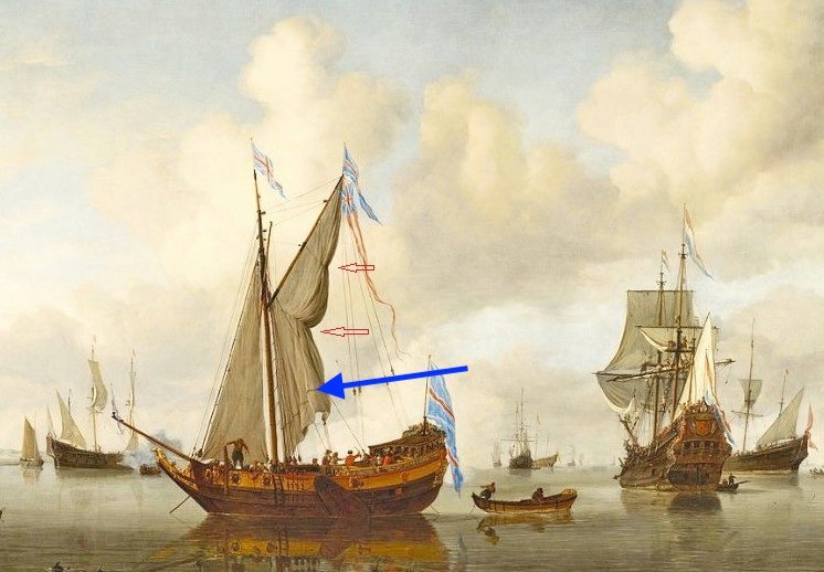
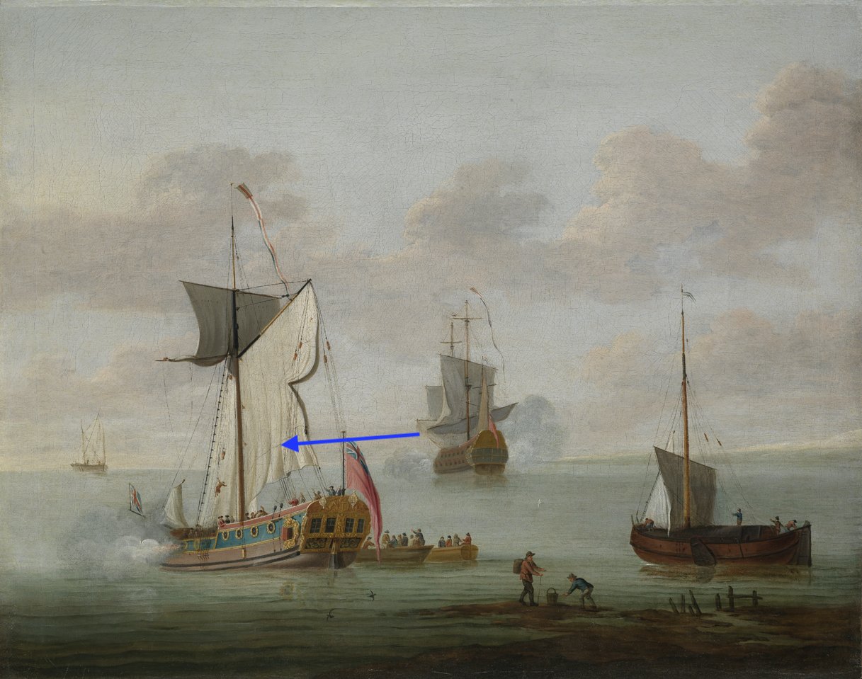
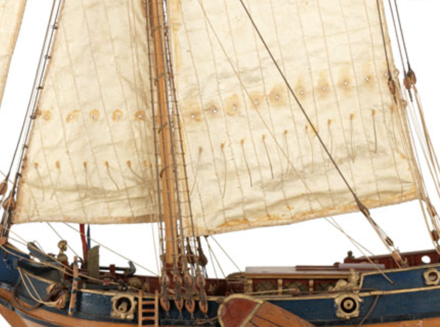
Hi Gregory, those are the brails, and they should be correct. In fact, its been my plan to show the mainsail "brailed up" like in this image. The painting, however, does show the line of what appears to the lacing of a bonnet. I'm reposting your image with a blue arrow pointing to the feature. The following painting by De Man shows something similar, again, I point to with a blue arrow. So, if that's not a bonnet lacing, I don't know what it is. Just a reinforcement seam of some kind?
- 82 replies
-
- 3
-
-
- Yacht Mary
- Mamoli
- (and 1 more)
-
Thank you Druxey. I would gladly make the sails without reef points or bonnets! Any thoughts about the serving of the shrouds or stays?
- 82 replies
-
- 1
-
-
- Yacht Mary
- Mamoli
- (and 1 more)
-
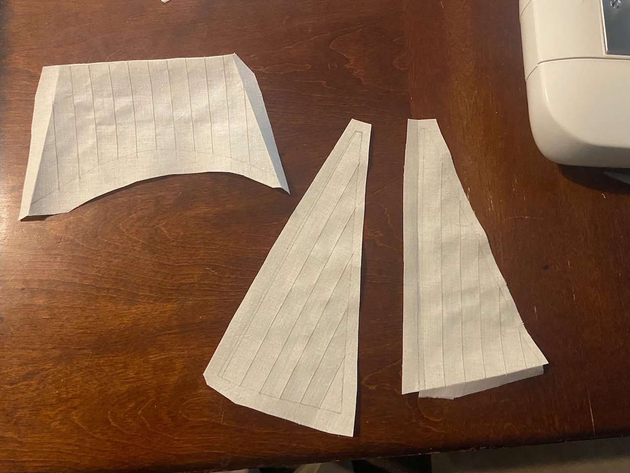
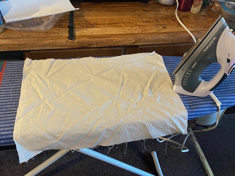
I'm jumping ahead now and working on the sails. At this scale, I'm going to stick with my practice of making cloth sails. I've made many sails from cloth, but still experimenting a little here and there to get the technique to work just the way I'd like. However, the issue here is the make up of the main sail. If you look at the sail pattern, the mainsail shows a row of reefing points. My last Charles Yacht model had a bonnet. Not sure what is correct, but thought I'd put this question out here. The Royal Museums Greenwich website shows a model of the Mary with reefing points in the main and stay sails, no reef bands, and a row of holes in the sails. One for each reef point? Of course, I could just stick with the Mamoli instructions and add these reef points to the main sail, which I might just do, since It's simpler than lacing a bonnet anyway. Just wondering what might be correct? Also, since I'm more accustomed to later period ships, and mostly larger ones, if the forward most shroud and mainstay should be served? Also the eyes of the shrouds around the masthead? Of course, kit instructions never tell you to do this, even if it was actual practice. Here, I'm not so sure about. Seems to me that since there isn't much to chafe against, the foremost shroud would not be served. But, at the mast head? And the main stay? Again, since this is mostly a continuation of the original builder's model, I'm sure he would not have done any serving, so just going by the kit instructions is a safe route. But, I'd like to better understand this.

- 82 replies
-
- 1
-
-
- Yacht Mary
- Mamoli
- (and 1 more)
-
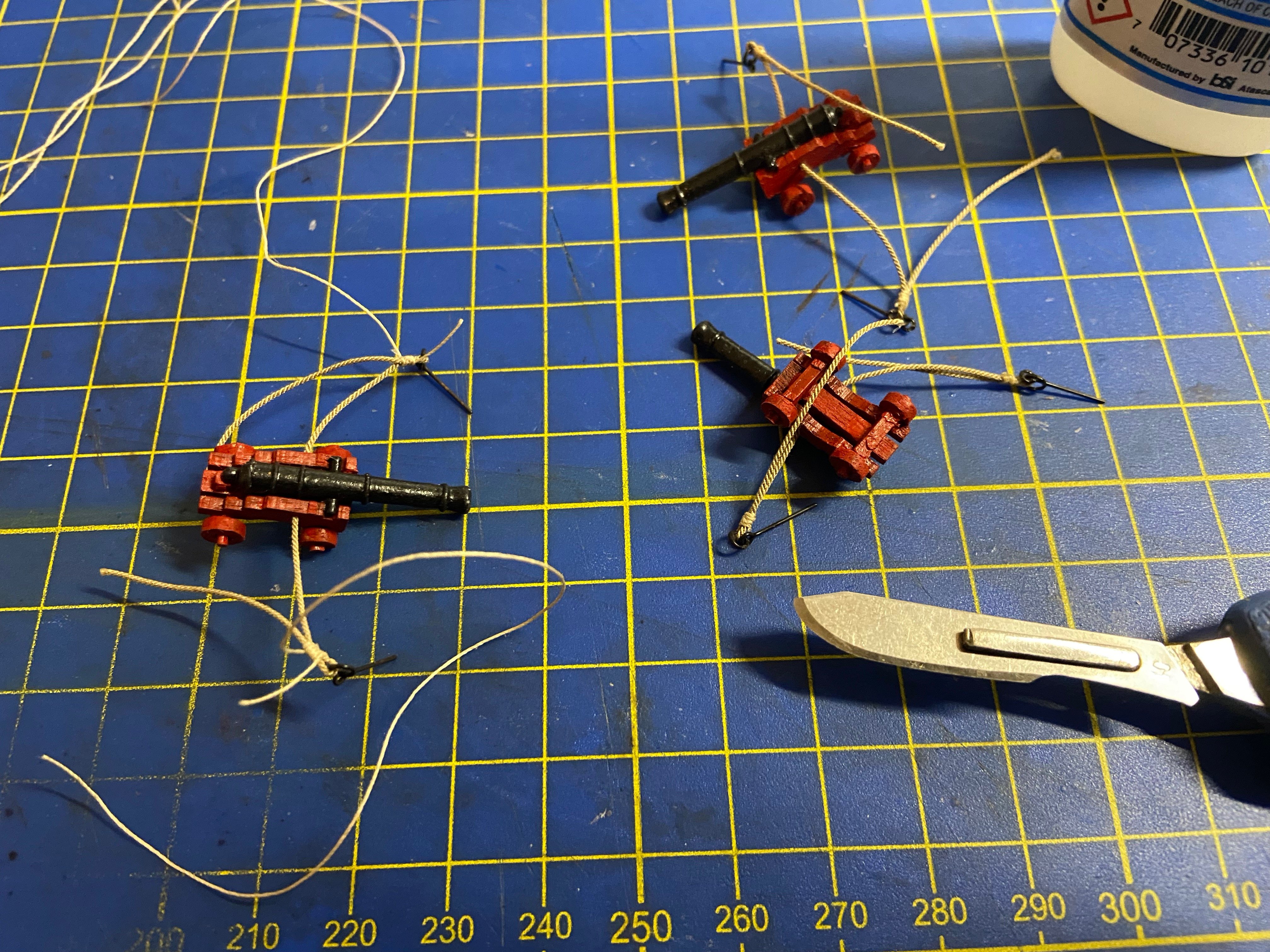
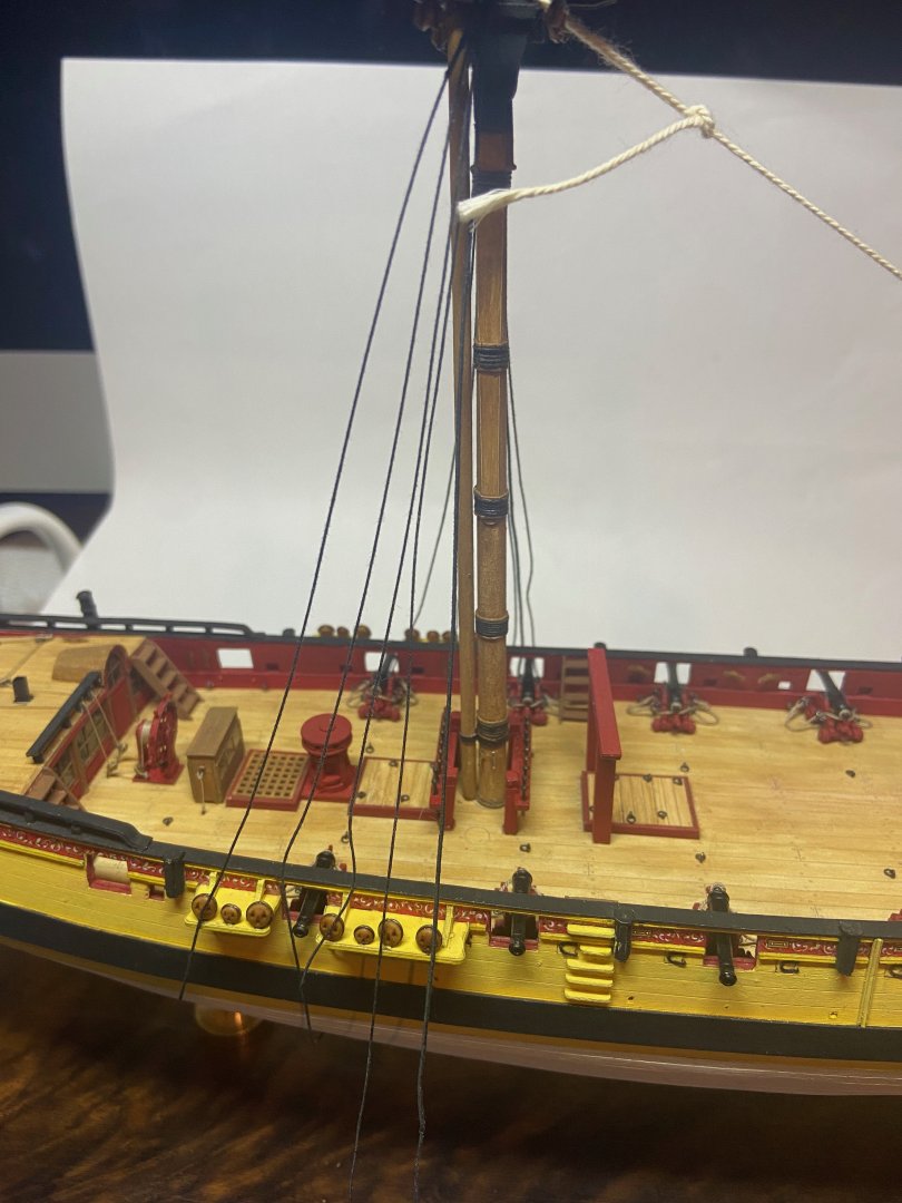
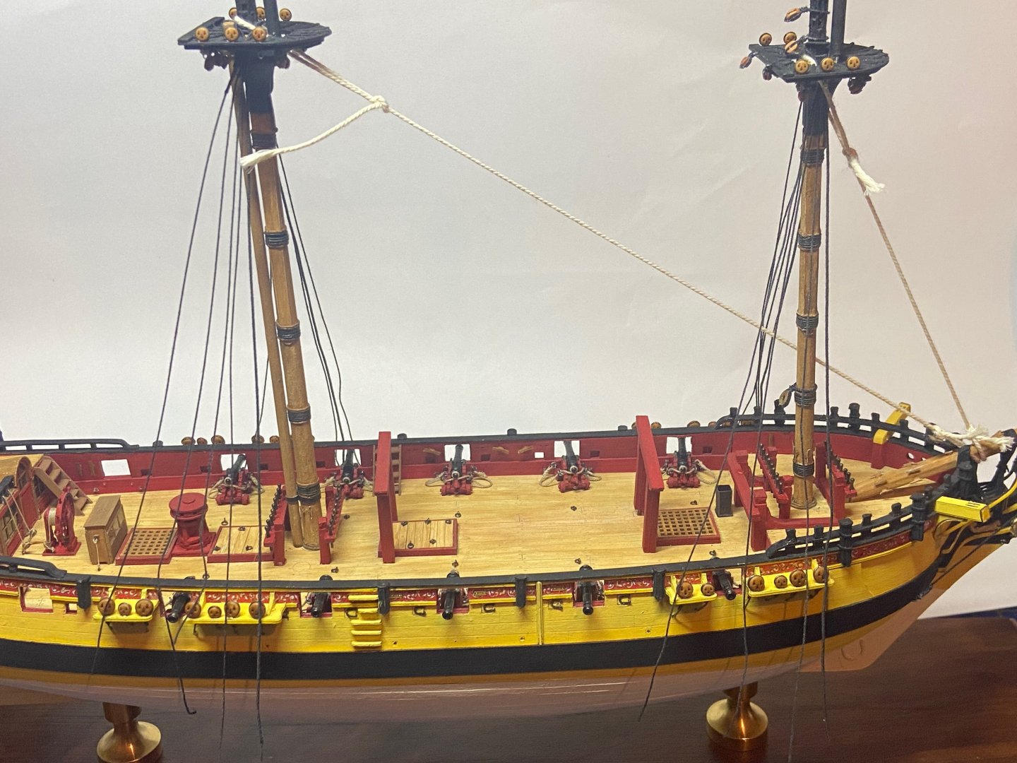
Thanks Patrick, I appreciate the nice comments. I had a bit of a slowdown over the past week, but I think I should be on a more regular ship modeling schedule again. Here's the most recent progress I made on the Yacht Mary. The lee boards were already made, but there was no pivot for it, so I drilled them out, as well as the hull, to fit a small length of dowel. Also assembled the anchors and cleaned up the anchor stocks. I used black thread to wrap the stocks. I think I need better lighting, because I had a hard time seeing that the wrapping wasn't particularly straight. But, I did manage to wrap the rings on the anchors without too much problem, and then added the anchor cables. When I first received the model, it had the hull ladders still intact. But, in the process of going to another ship modeler and then back to me, the ladders got broken. So, I had to remove them completely and rebuild them. I'm not really happy with the new ladders, because of the way they had to curve slightly under the hull. I'm not sure if that's because of the way the hull was built, or if perhaps they're not supposed to actually be flush with the hull as these will be. I suppose they should be straighter, but on this model, they would end up flaring out from the hull at the ladder bottoms, which would seem stranger to me. I didn't do much to the guns and carriages, except to paint them. They carriages were initially natural wood color, and the barrels were painted black, but were chipped. So, I painted the carriages and barrels, and then took a length of line, and threaded them through the carriages for breechings. Note that this is the style of Dutch gun carriages, but the Mary was Dutch built, so this should be correct. Not sure at this point if I'm going to add gun tackle and train tackle. Finally, I added the remainder of the decorative piece at the stern. It was a bit of a challenge to fit these parts, and the work left some notable gaps. But, I think it looks okay. I'm starting to work on cleaning up the already made spars, and fashioning flag staffs. I've also decided to use Chuck's ULTRA rigging line and 3D printed blocks and deadeyes on this one.


- 82 replies
-
- 6
-
-
- Yacht Mary
- Mamoli
- (and 1 more)
-
Gregory, I don't think you're cluttering up this log at all. I'm mostly just sharing about the model I received and how it's getting finished over time. I'm not demonstrating any special techniques or trying to illustrate anything special, other than to show that I'm actually doing something! 😀 Thanks for sharing the link to Lloyd McCaffery's model. Such beautiful work!
- 82 replies
-
- 4
-
-
- Yacht Mary
- Mamoli
- (and 1 more)
-
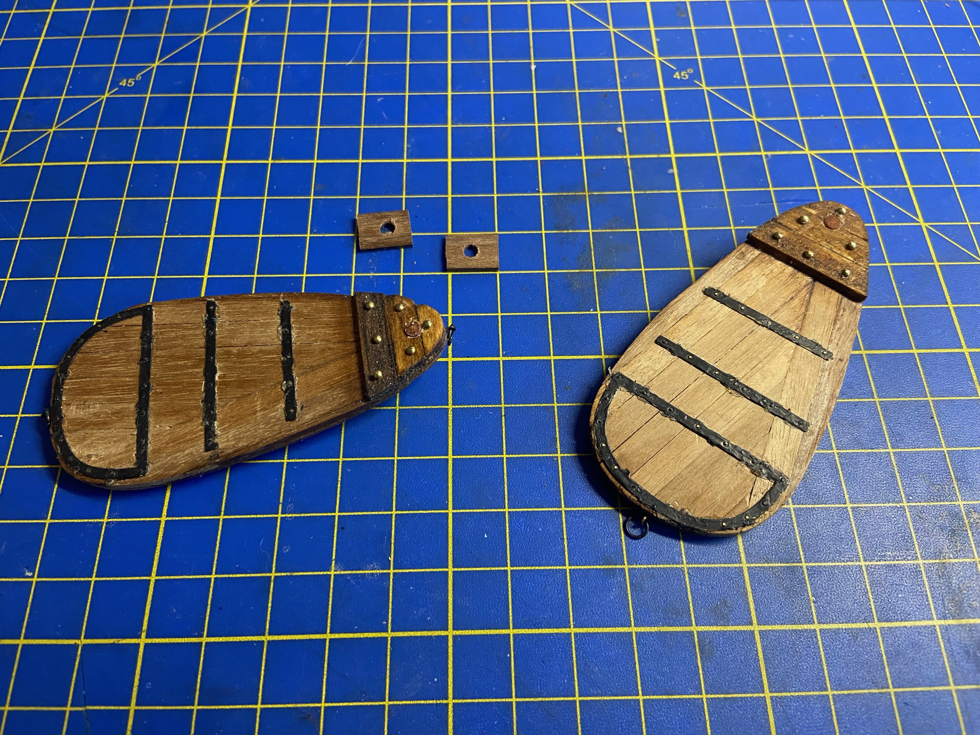
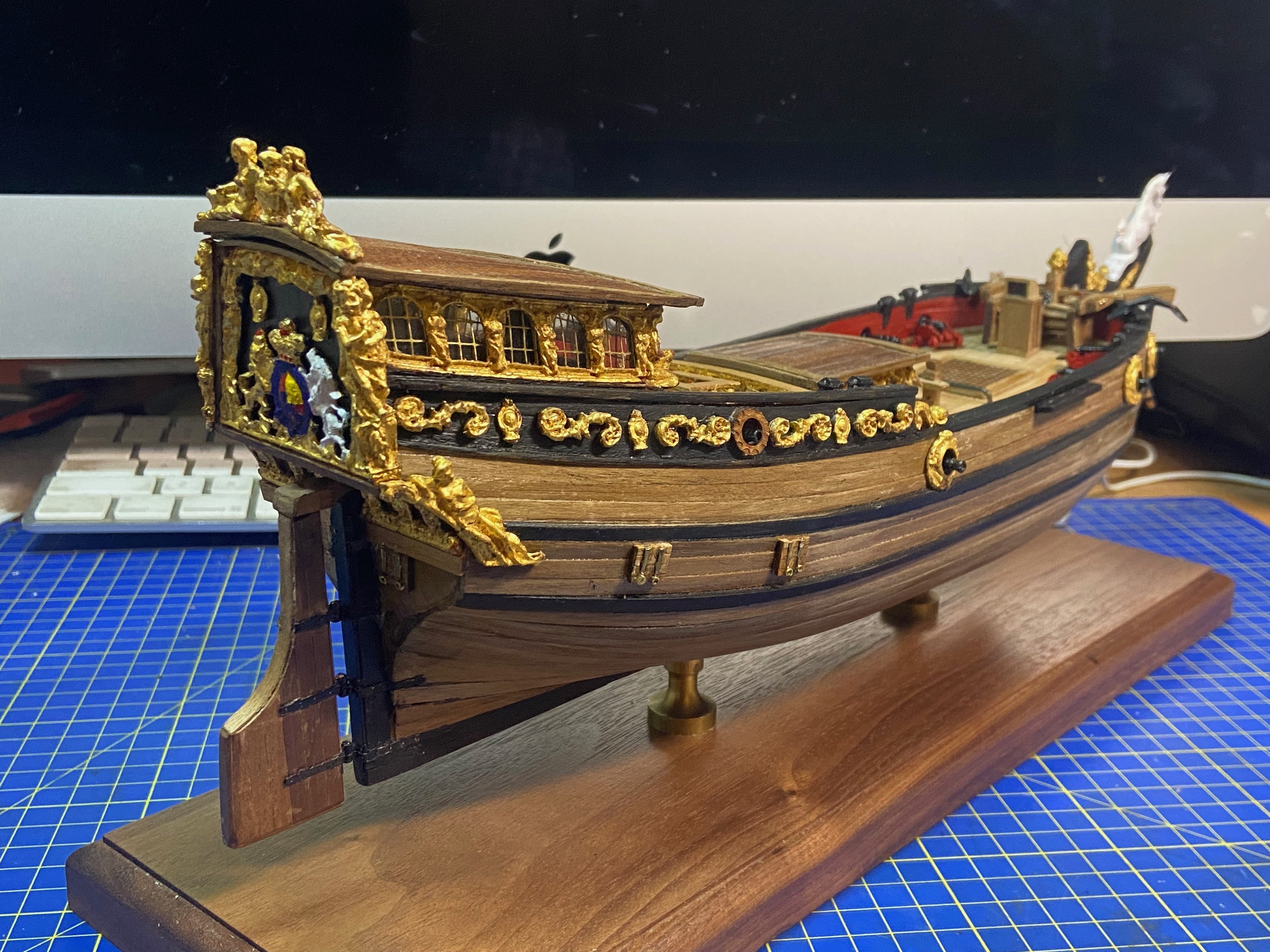
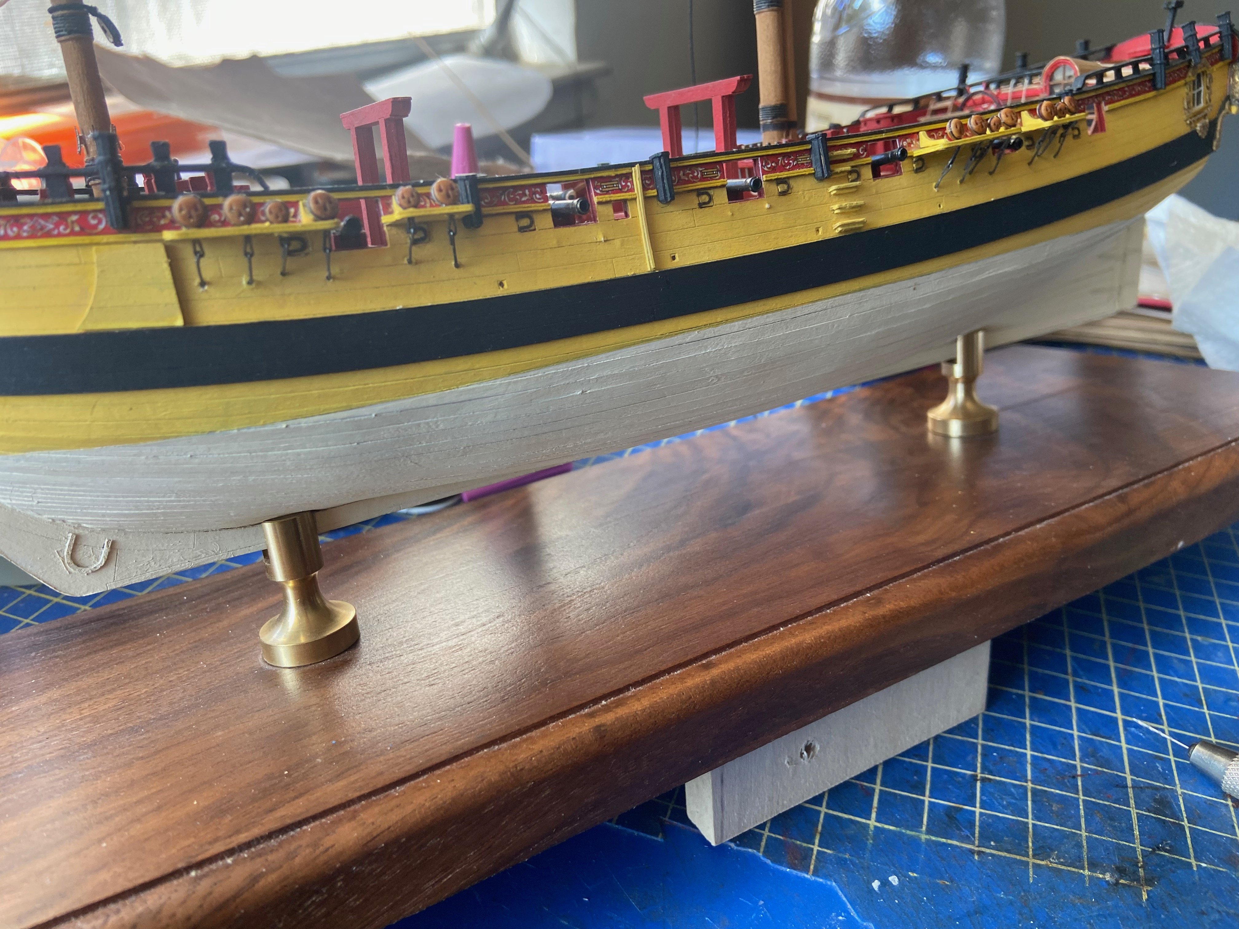
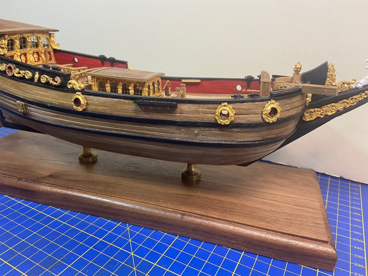
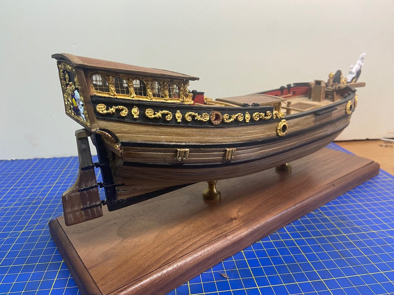
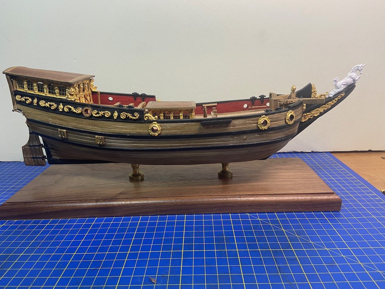
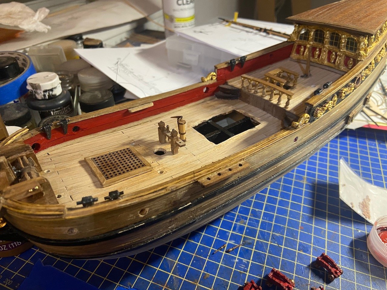
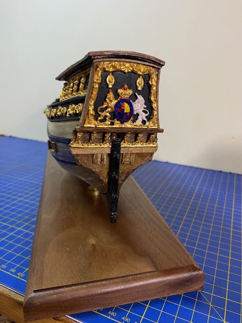
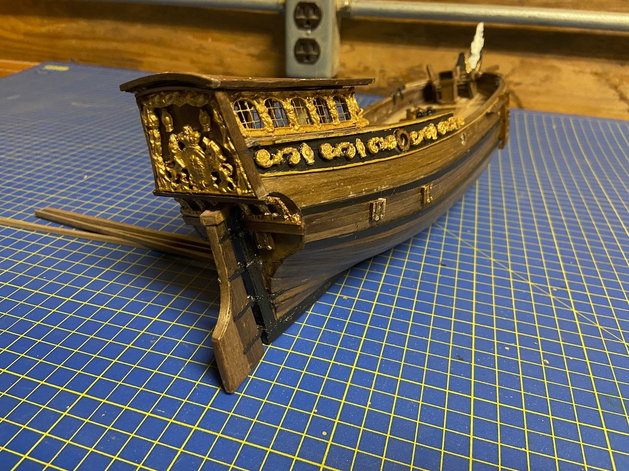
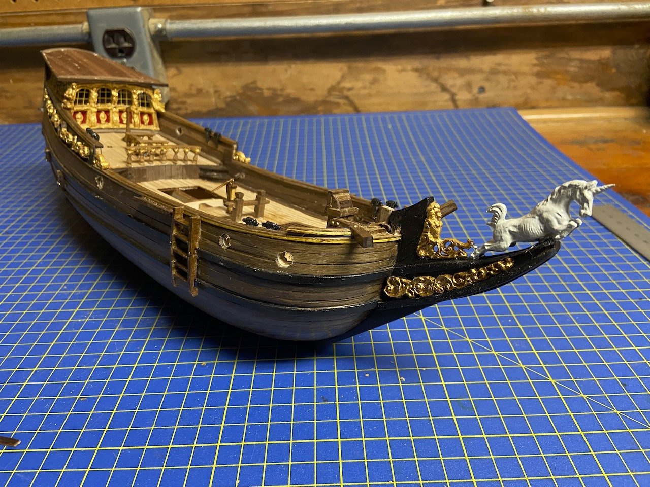
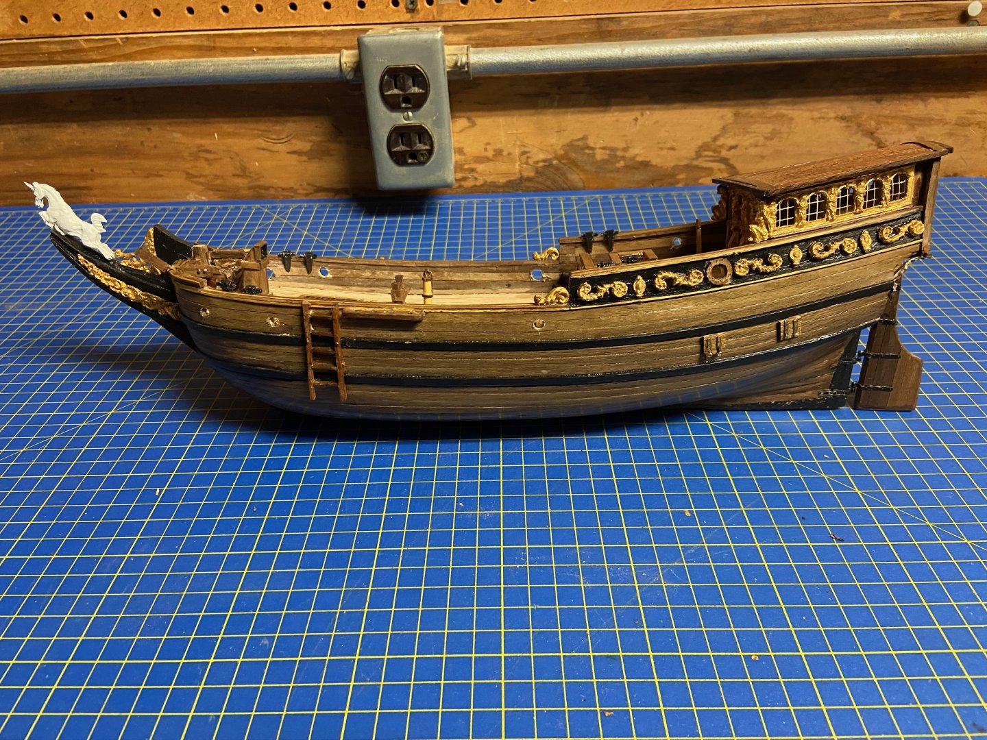
Here's some of the first work I did on the model. I decided to add a little more color to the model, so I painted the bulwarks the same shade of red I used on my Charles royal yacht. I'm doing the same with the gun carriages. Part of the reason is that the bulwarks wood was a bit splintery, and there were issues apparently when the builder was cutting the round gun ports. Also, I didn't like the way that Mamoli had the caprails built up from layers of strip wood. It must have made construction easier, but the visible layers of wood seemed distracting, so I went ahead and painted those as well as the moldings around the decorative section of the bulwarks and the channels. I considered using a strip of light colored wood over the moldings and maybe the edge of the caprail, but decided not to, at least not at this time. I rebuilt the chimney that's just behind the windlass, added the decorative hawse pieces at the bow and drilled the hawse holes. The gun ports were a bit of a challenge, as some of them didn't line up correctly. Another reason I chose to paint the bulwarks, so I could hide any corrections. The round ports on one side had only been started, so they were too small. But, a bit of filing opened them up and adjusted their heights and alignment. Decided that the model was far enough along to safely mount it. I didn't want to use the included stand. Those things are usually too flimsy and don't provide a means to really secure the model to the base. I just used the classic brass pedestals. That little deck structure hasn't been permanently attached yet. I want to add the guns before I permanently fix it to the deck. Oh, and on that and on the stern cabin, I added acetate for the windows, which were left open by the original builder. I think I just used canopy glue to secure them into place. Yes, before you comment on it, that gap between the rudder and stern post is... well, it's too large. After repairing the rudder and the rudder irons, I left it the way it was originally built. If it bothers me too much, I may just clip off the stuff in between, fake the hinges, and pin the rudder to the hull. Just haven't felt the need yet. Lastly, I saw some photos of other Yacht Mary builds and really like the splash of color painted on some of their transoms. So, I went ahead and added some color to this one. I'm not sure if I can handle painting any better detail, but I may try. Just not really ready for it yet. I considered doing more, but I really just wanted it to have a little bit of color. Any more, and I might feel the need to paint too many other details as well. Again, this is not intended to be an "accurized", and I'm trying not to undo too much of what the original builder did. But, as far as kit-built models go. It is started to look rather nice, and I'm happy about that.
- 82 replies
-
- 7
-
-
- Yacht Mary
- Mamoli
- (and 1 more)
-
Gregory, thanks for that link, some beautiful photos of that model there. I wish I knew more about the small details of Dutch ships. I know there are various resources to draw from, but it seems you really have to dig around and research. A little more involved than I want for finishing this model. I'll hang onto my unstated Yacht Mary kit for now (though I'm trying to thin out my model kit stash), and maybe someday I'll work on my own model from the start and incorporate those details.
- 82 replies
-
- 3
-
-
- Yacht Mary
- Mamoli
- (and 1 more)
-
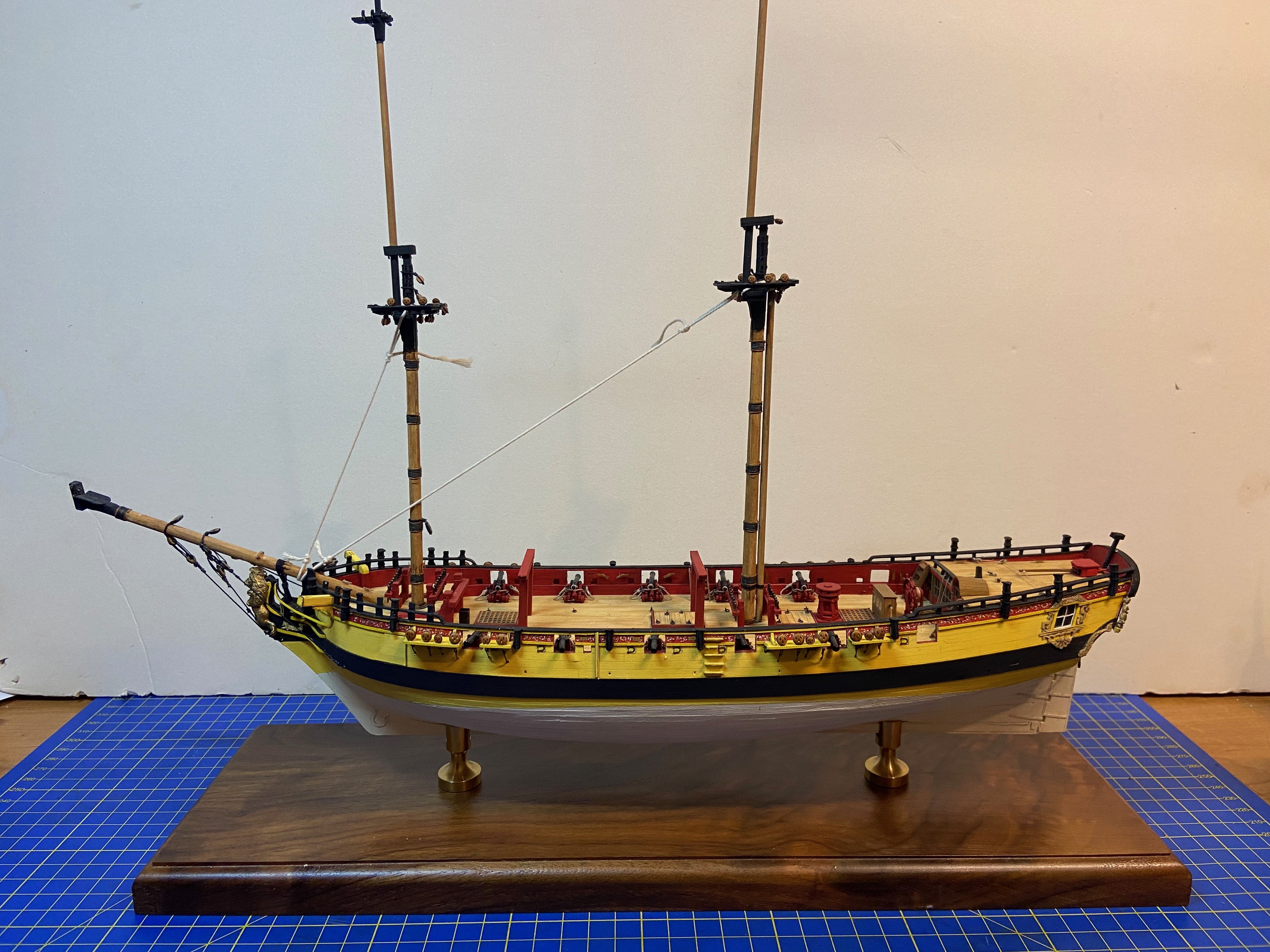
Hey everyone. My apologies for the extended break. I ended up with plans to finish up a model that was started by a ship modeler who passed away a couple years. It's the Yacht Mary, and with the completion of my Charles Royal Yacht, I figured I could wrap this one up pretty quickly. It's come along pretty well, and I'm hoping to finish it in the next month or two. It's my intention to begin resuming my HMS Wolf build immediately after that, or even a bit before the Mary is done. It won't be that long, as I'm just starting work on the Mary's sails now: Back soon!
-
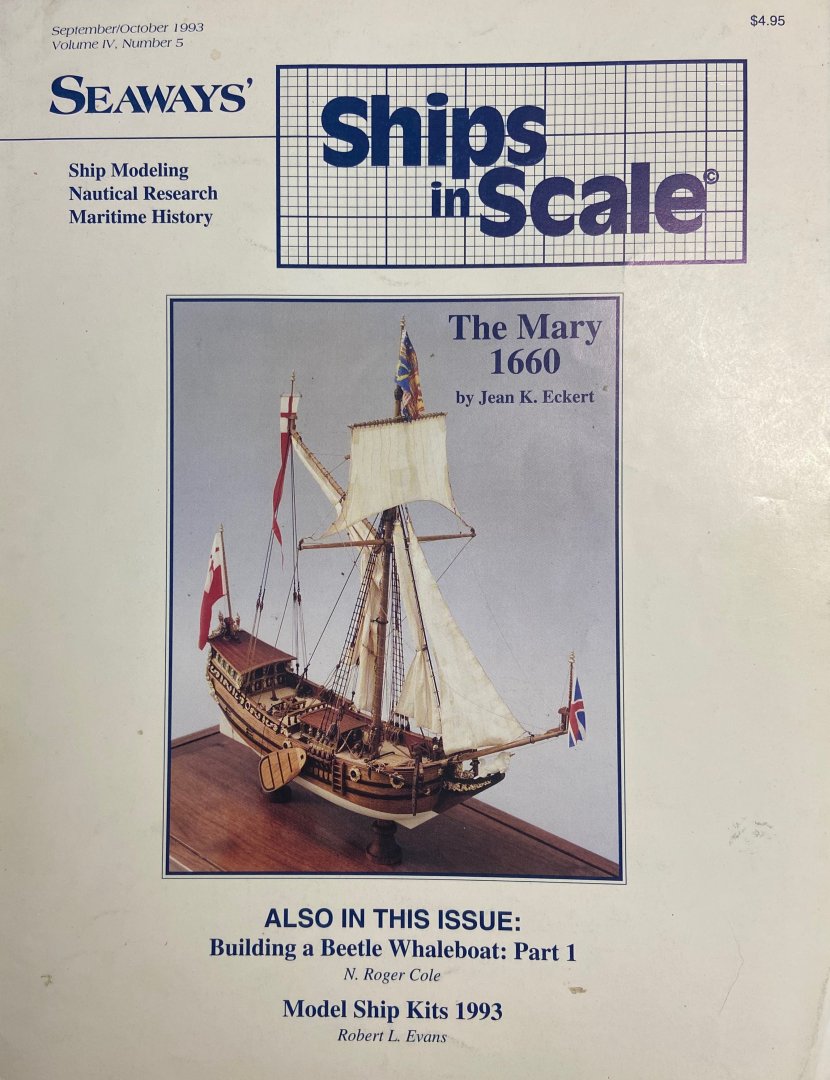
Those following my HMS Wolf card model build may be wondering where I disappeared to. So this is what I've been doing for the past couple months. A couple years ago, I bought a Mantua/Sergal Sovereign of the Seas kit, unstarted, at an estate sale. I guess the sellers were so happy to move the kit that they threw in a partially started Amati Prince (yes, the rare, and huge Amati Prince in the wooden box), and this partially completed Yacht Mary. Having recently completed Woody Joe's Charles Royal Yacht, and having so enjoying modeling a royal yacht, I was interested in working on this new acquisition. But, the model left my possession for another modeler to work on. But, over time, I thought about how the original builder, a Mr. Richard Fletcher who lived up near Placerville, CA, was building this as a wedding present. I didn't know the man or the details of who it was supposed to be fore, but I didn't know that the builder's widow really wanted to know that her late husband's models were being continued. Later on, finding out that the modeler I had passed this onto was turning into some random fantasy ship, I decided to try to rescue it, with the intent of finishing the model and presenting it back to the Mr. Fletcher's widow. So, with my new plans, I managed to get the model back, and start working on it. My intent is not to make a perfect model of the Mary, nor a perfect model of a Dutch yacht. Rather, it's to essentially take Richard Fletcher's work and to continue the model to completion without changing too much. That's not to say I would avoid ANY "corrections" to the build, but mostly to avoid changing the nature of the model more than I need to. While I don't have any photos of the model after it came back into my possession, I did have to clean up some alterations that were done to it, such as the removal of a "poop deck" railing that was installed for the fantasy model, and a couple other minor things that had been broken since I saw it last. Aside from that, I noticed the original builder had some trouble with a few things and left a big gap just between the transom and the gallery windows casting. So, I did a few small modifications to make the model look better. By the way, I've always been interested in modeling the Yacht Mary, and even have an unstarted, original Mamoli kit, which gave me access to the original, full-sized kit plans, which I found helpful. I think my interest in the model dates back to seeing the late Jean Eckert's build in the old Seaways' Ships in Scale magazine. She, by the way, started and ran the South Bay Model Shipwrights club that I'm a member of still today. I'll post a series of photos later to show the progress to date. I'm hoping to complete the model by June. So, this will not be a long and detailed build log. Mostly just wanted to be able to share about the work. Note: I will be getting back to my HMS Wolf build shortly!
- 82 replies
-
- 11
-
-
- Yacht Mary
- Mamoli
- (and 1 more)
-
Does anybody know when gun port wriggles appeared? These are the wooden drip diverters that kept water from running down the hull into the gunports. I occurred to me today that I've only ever seen them on HMS Victory and models of her. Anybody know?
-
The only thing in that example is that they planked the inside of the bulwarks INSTEAD of adding the timberheads. I would agree with Snug Harbor Johnny's recommendation, but as RossR says, make sure your cap rail is wide enough to cover the planks and the timberheads.
-
I will say that I do like the idea of the gallery banner showing just one image from an album. I often feel like when I post a bunch of photos, right after another builder has posted theirs, that I'm kind of unintentionally blasting them off the banner before others may get a chance to notice their work. But, I'm not sure if that's a feasible function. As for videos and links, I too am not particularly fond of them and find them boring. I would go so far as to say that I avoid build videos like the plague. But, that's just me. I know many people love build videos.
-
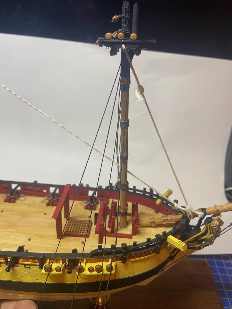
Thanks Druxey! Actually those stays are just temporary to hold the masts steady while I work on the shrouds. They'll come off and be replaced with real stays, which is why these are white. In earlier photos, you can see the hearts that you're talking about that the forestay will later get rigged to. As for the mainstay, I don't know how accurate it is, but I'll be following the provided plans, which have it running to a heart that you can see located on the foremast. I'm glad you're keeping an eye on my work!
-
Today, I finished serving the shrouds. Boy, it's been a long time since I've done this kind of work. I felt like I was having to re-learn a lot, and they took me a while to finish.

-
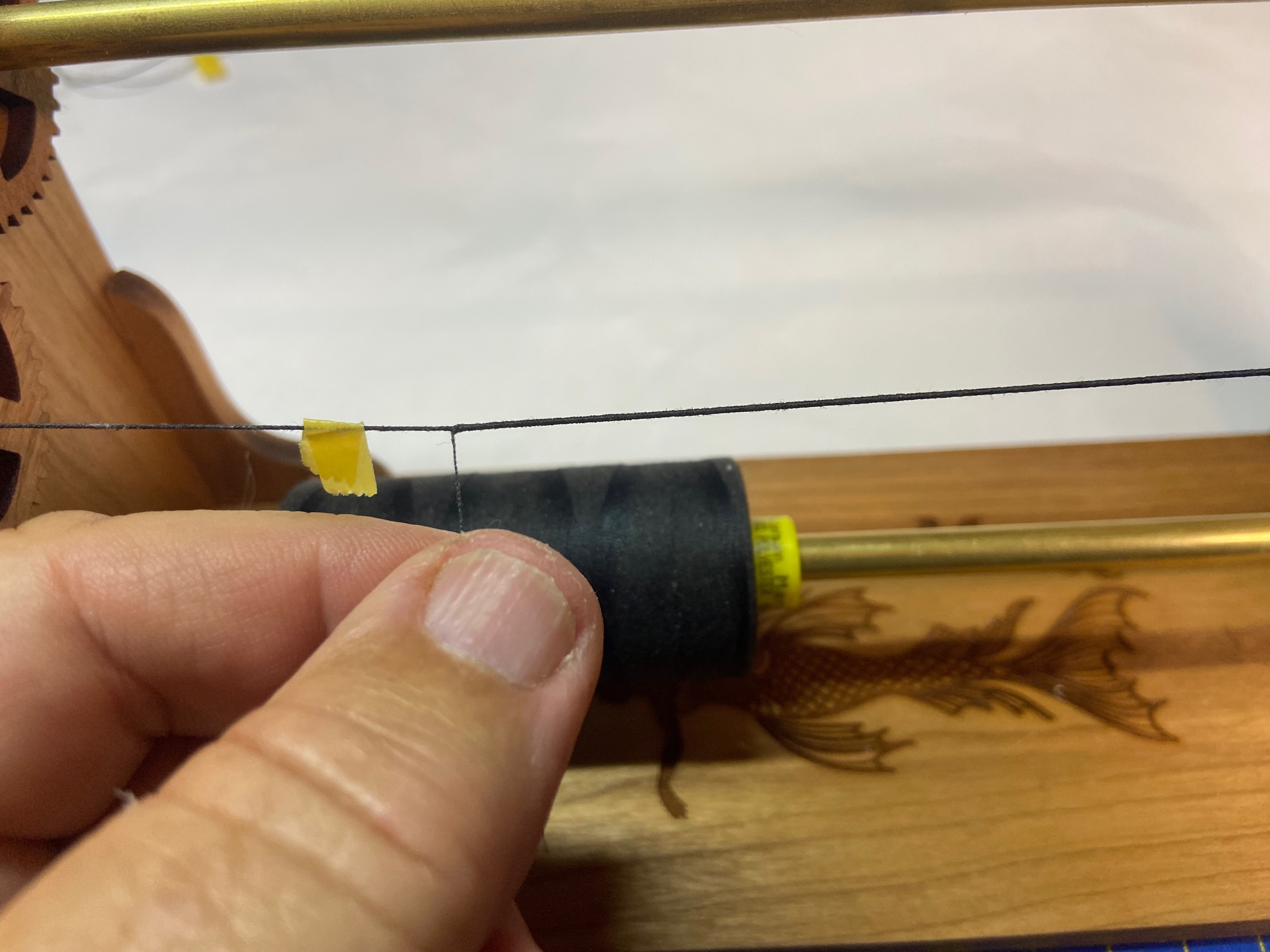
Hi Chris, your Brig Phoenix is looking great. Too bad the MK kits are pretty well gone at the moment. It would make a nice companion to HMS Wolf, being similar size and the same scale. I have to say, I'm rather enjoying working at 1/72 scale. Jeff, it's for the new optional "Serve-Writer" attachment. Unfortunately, I'm having trouble getting it to interface with my Mac. Must be a PC-only thing... 😁 brunnels, thanks for the nice comments. It requires a lighter touch. But, it's also a lot sturdier than most people think. Still, the whole reason I've been "upgrading" the chainplates is so I don't tear the channels off the model while trying to rig it. I've built two other single-masted paper sailing ship models without any rigging problems. This is the first with two masts. Will I be successful? Stay tuned!
-
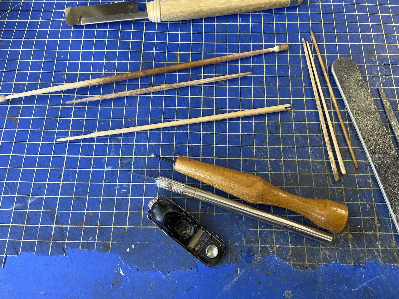
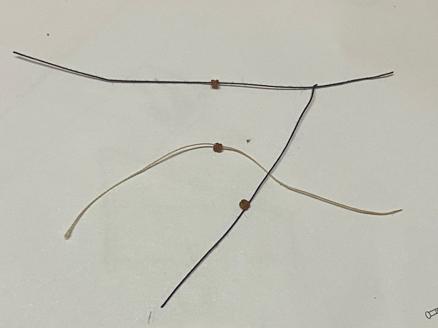
No real progress yet. Been working too much. But, I did manage to try threading those 2mm blocks. Worked out fine using 0.1mm Amati tan rigging line, as well as some of BenD's (RopesOfScale) 0.25mm black cotton line. Of course, in all cases, I had to use a dab of thin CA and trimmed the end to a point to thread it through. Clearly, I didn't wax any line here. Also managed to complete assembly of my Syren Serv-O-Matic. I can start working on the shrouds and stays now!

- 108 replies
-
- 10
-
-
I have to agree that the un-even holes are hardly noticeable on a model, at least when viewed by others. But, at the same time, when I put them on my models, I as the builder notice, and that matters a lot to me. Those mass produced wooden ones are pretty standard. It's really hard to find ones that are proper, with evenly spaced holes. I'd be very curious as to the production process. Anyway, the most perfect deadeyes are Chuck's and BlueJacket's pewter ones. BlueJacket even has them with grooves for all the holes except the one where the knot goes. So they're upper deadeyes are different from the lower ones. But, I'm very happy with the 3D printed ones I received from Chuck recently. Not just the holes, but overall appearance and shape.
-
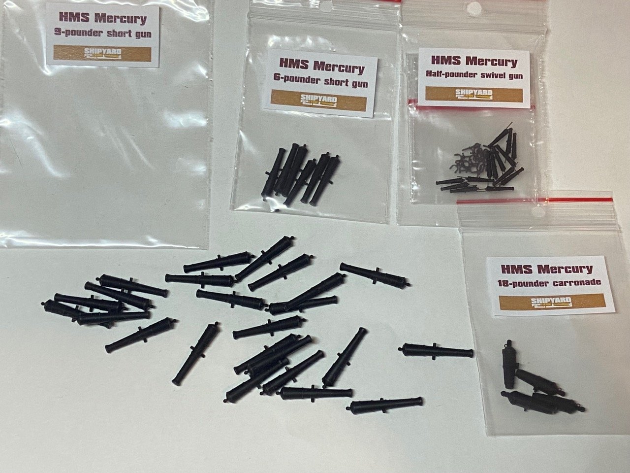
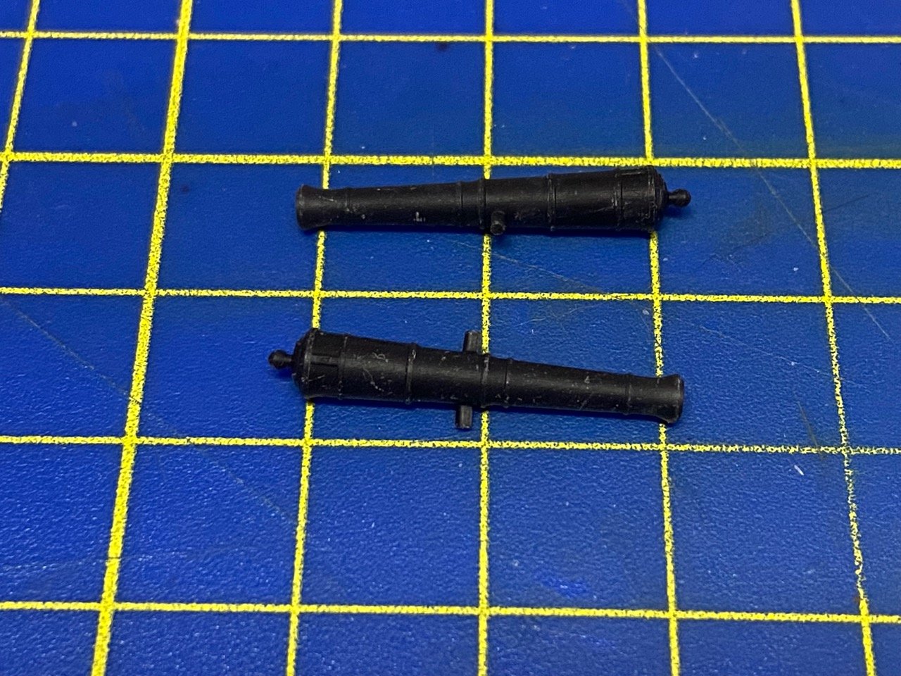
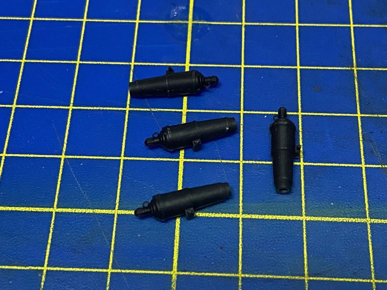
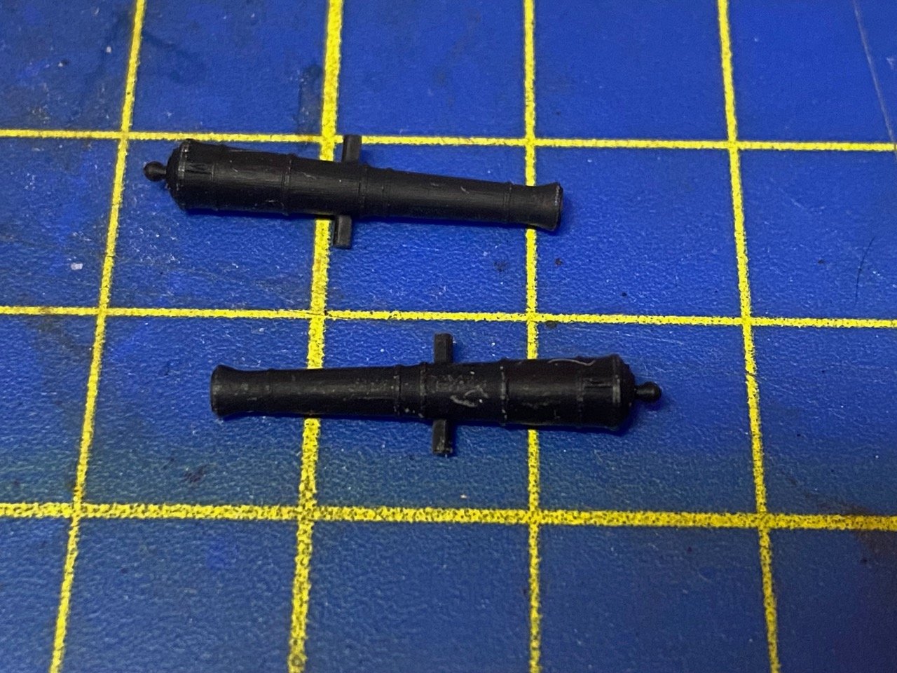
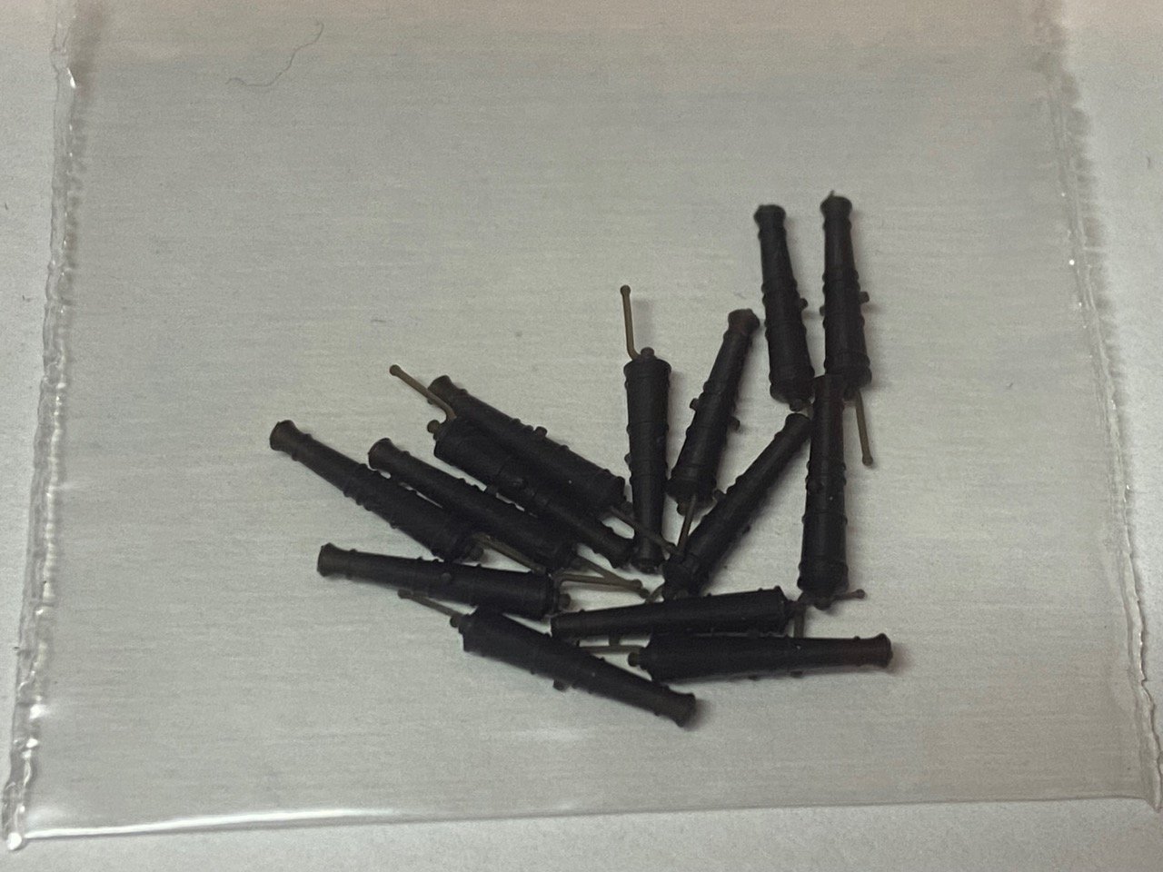
Anyone who has been following this log shouldn't get their hopes up that I'm resurrecting this project... at least not yet. However, just in case, and also to help rate a new product from Shipyard, I got myself their new 3D printed cannon barrels set for HMS Mercury. The set, which should be identical to includes 24x 9pdr short guns, 6x 6pdr short guns, 4x 18pdr carronades, and 14x 1/2pdr swivels. Here they are in the same order... I'm amazed at how fine those handles and yokes are on the swivel guns, and that they're not broken (yet)! The only issue I've run across is that the trunion on one side of one of the 6pdr guns was broken off. The piece was still in the bag. Might be too tiny to hang onto to make the repair. Other than that, the guns looked good. Anyway, I thought someone building this or one of the other Shipyard 1/96 scale frigate models, or their HMS Victory model, might be interested. I'll definitely use these if I do end up continuing with this model. And, I do have reasons to try picking it up again, so who knows?
-
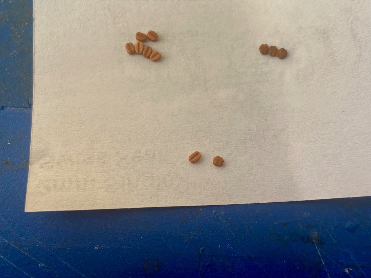
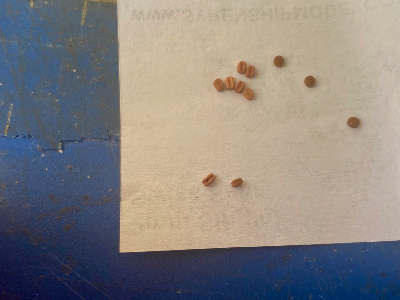
Managed to finish these preliminary chainplates yesterday. Hopefully, this will make the rigging of the shrouds easier, which is coming soon. Meanwhile, I just recieved some of Chuck's 2mm 3D printed blocks to use for the gun tackles. Wow, are these things tiny! I have some of Chuck's original 2mm pear wood blocks, and the size difference is more than I'd expected, at least visually. Wooden blocks on the left, 3D printed on the right. I measured the wooden blocks and they come out to 2.13mm long, the 3D printed ones are 1.92mm. So, they really are very close. The 3D printed ones are a little shorter and noticeably narrow, so they SEEM so much tinier. I guess the test will be to see what a gun tackle and train tackle look like, rigged. This assumes, of course, that I can actually add them to already placed cannons... 🤔


- 108 replies
-
- 11
-
-
With yesterdays meetings behind me, I'm turning my energies back to HMS Wolf. The new deadeyes are all stropped now, and I'm trying to rig up "faux" chainplates, which I'm expecting I will cover with some kit provided paper parts that LOOK like chainplates, but have no strength to them. What I'm installing are chainplates that don't look right, but should add strength to support the shrouds. After these are all done, I'll face them with the kit pieces. And, if that doesn't look right, I may try to come up with something that makes these pieces LOOK like they're bolted to the hull. Not perfect, but at least it's progress! I'll add that the amount of support these provide are pretty limited on this model, as many of the wires can only penetrate into the hull a very short distance, as they'll are above deck level. Getting the length right for these short wire pieces is somewhat painstaking work. Were this wood, I could apply a lot more pressure in forming these links.
-
Hi Jeff, Vallejo isn't the greatest location, but I think it's better than it was when I first moved to the area in 2000. The museum, however, has been very accommodating, and works out very well for us. Yesterday, we returned to the museum for the first time in... maybe 7 years(!). It worked out very nicely and they even have a bigger table now, which was great, as it gave us more room to spread out and share our model progress (or lack!). We're going to try to alternate our meetings between the museum and the Mare Island Brewing Company's Coal Shed taproom, which is a great location for beer and bar food. I think I mentioned before that one of our members has done some model work for one of the owners, so we're appreciated there as well. We were kind of hoping the Park Service would stick to their timetable and move the historic ships from Hyde Street Pier at SF's Fisherman's Wharf, to there, where they're supposed to be docked while the pier is being rebuilt.
-
Thanks for the encouragement, Jeff! I have to admit, I tend to have purist leanings, but with card models, I'm not good enough to stick to them. Anyway, these laser cut Shipyard kits provide wood for the spars, acetate for the windows, resin for the figurehead and some decorations, cloth for the sails, and turned brass barrels for the cannons and swivel guns. So, it's not really a purist's kit anyway. Plus, these deadeyes from Chuck look so darned good! I just received the 4mm deadeyes and, like all blocks and deadeyes I get, one size seems too big, and another seems too small. But, measured against the plans, the 4mm deadeyes are a good match, so I guess that's the way I'll go. I'll get to stropping now and post pics afterwards. In the meantime, I decided to upgrade my serving tools with a new Siren Serve-O-Matic (my Christmas present to me). I'm just now cleaning up the wood parts and assembling it now. I'll make use of this with the Wolf's shrouds and stays. Been a long time since I've done rope serving. I skipped it on some of my more recent builds. Progress on the Wolf is slowed up right now, as I'm trying to get some other things ready for a ship model meeting of the Mare Island Ship Modelers at the Vallejo Naval and Historical Museum next week. This marks the resurrection of the group and its official return to the museum. However, I did start to get started on the foot ropes. I know some modelers just use wire for the stirrups, but I think they tend to look too perfect. So, I prefer making them from rigging line. More after the meeting next weekend...
.jpeg.decac556476ddcb56a00b08fe636adae.jpeg)
- 108 replies
-
- 11
-