Glenn-UK
-
Posts
3,175 -
Joined
-
Last visited
Content Type
Profiles
Forums
Gallery
Events
Everything posted by Glenn-UK
-
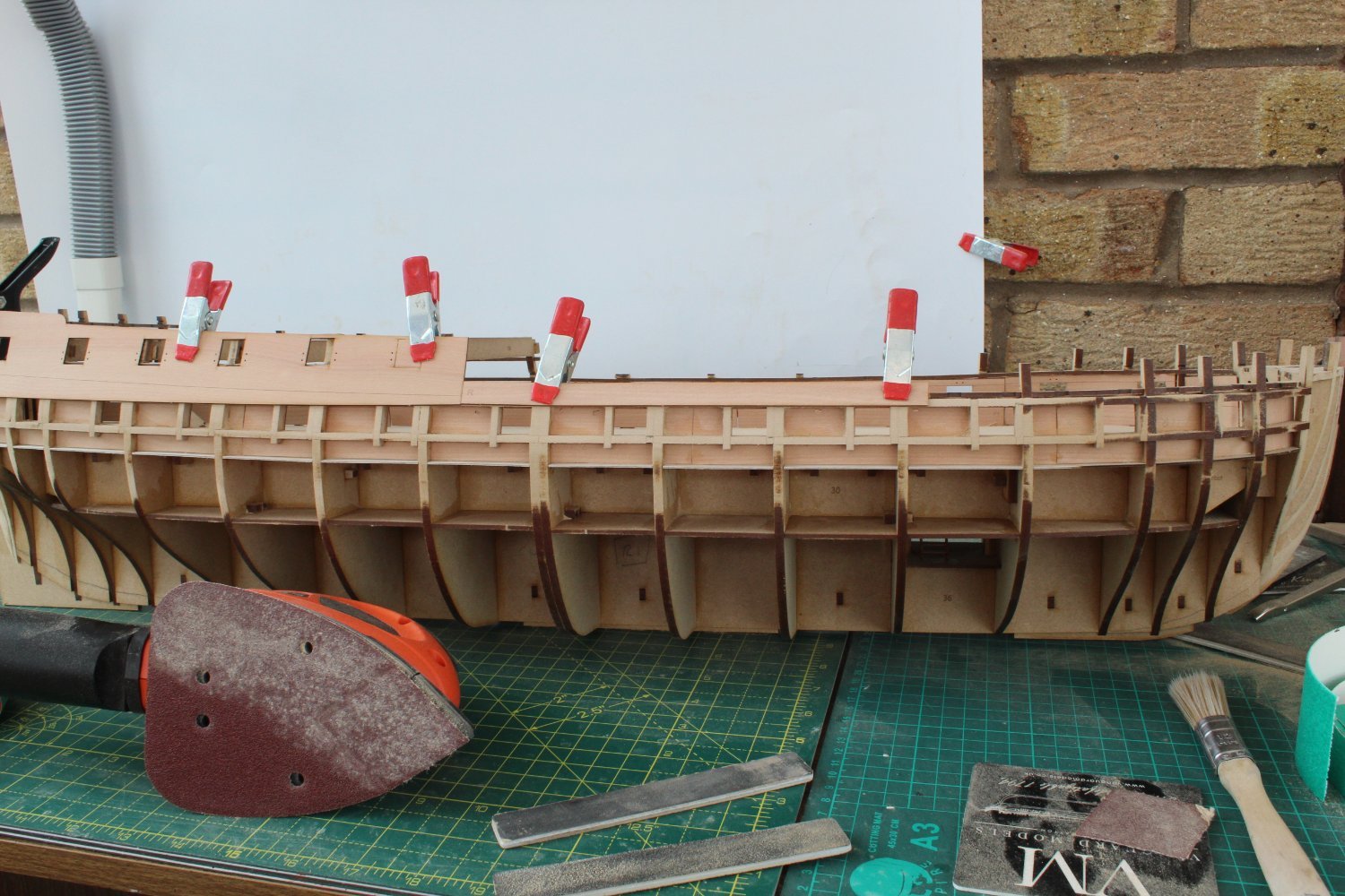
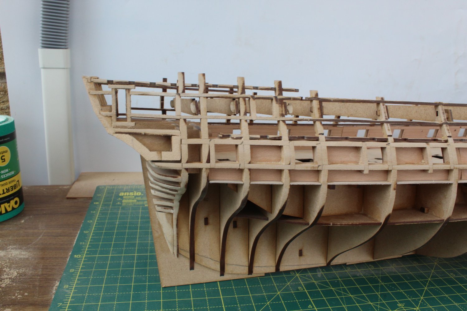
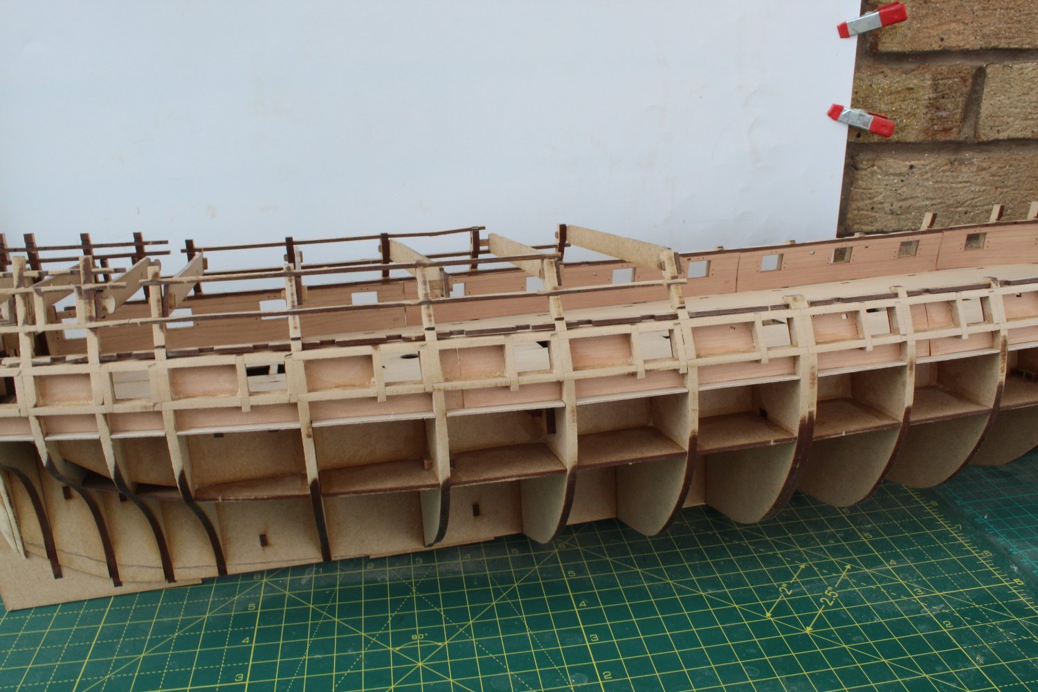
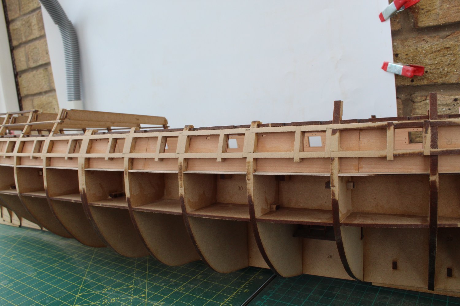
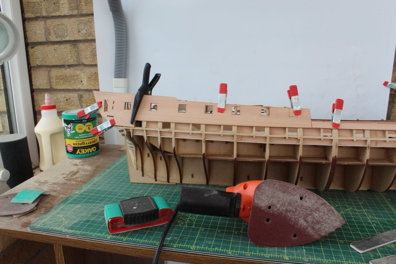
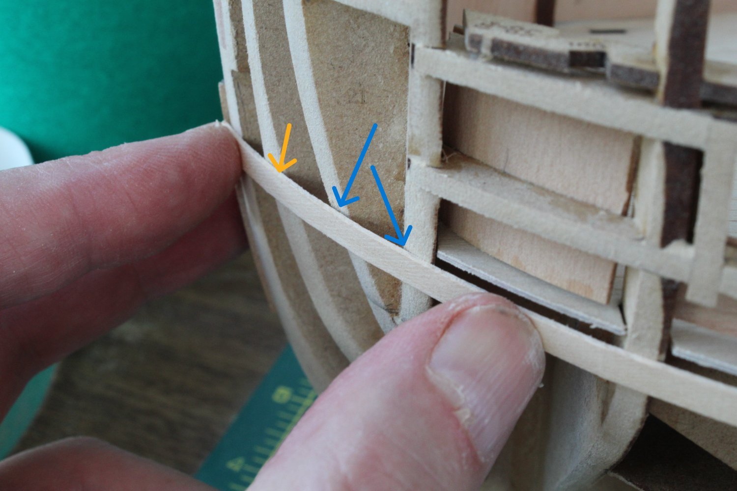
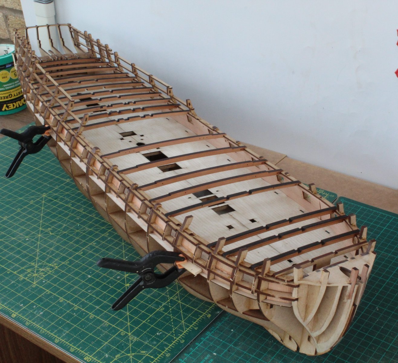
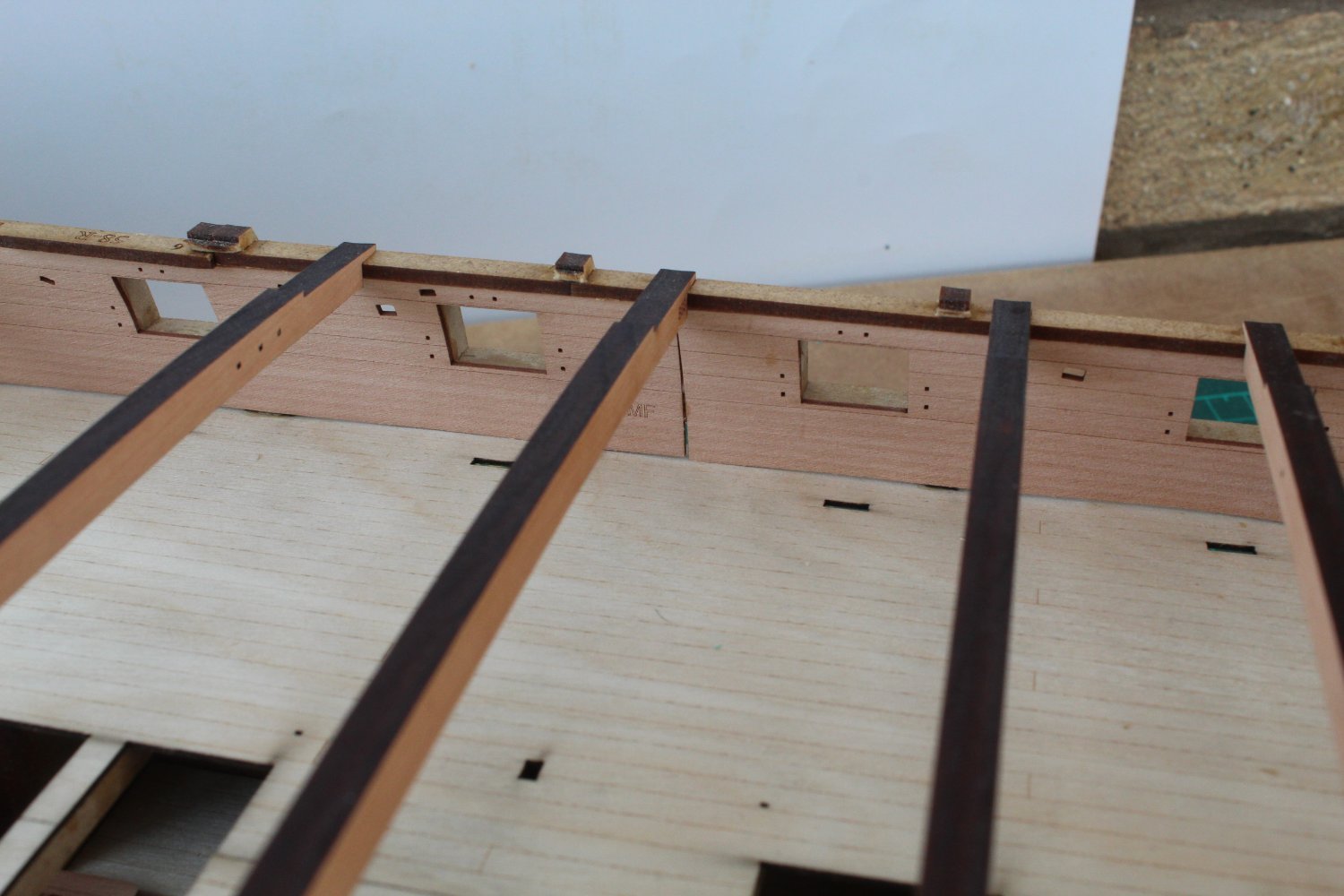
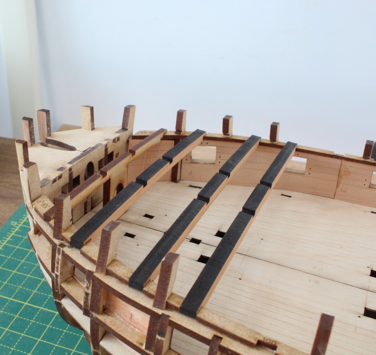
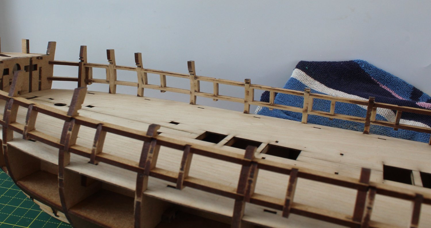
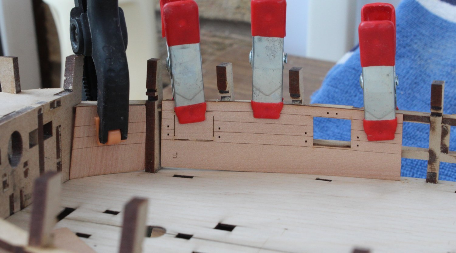
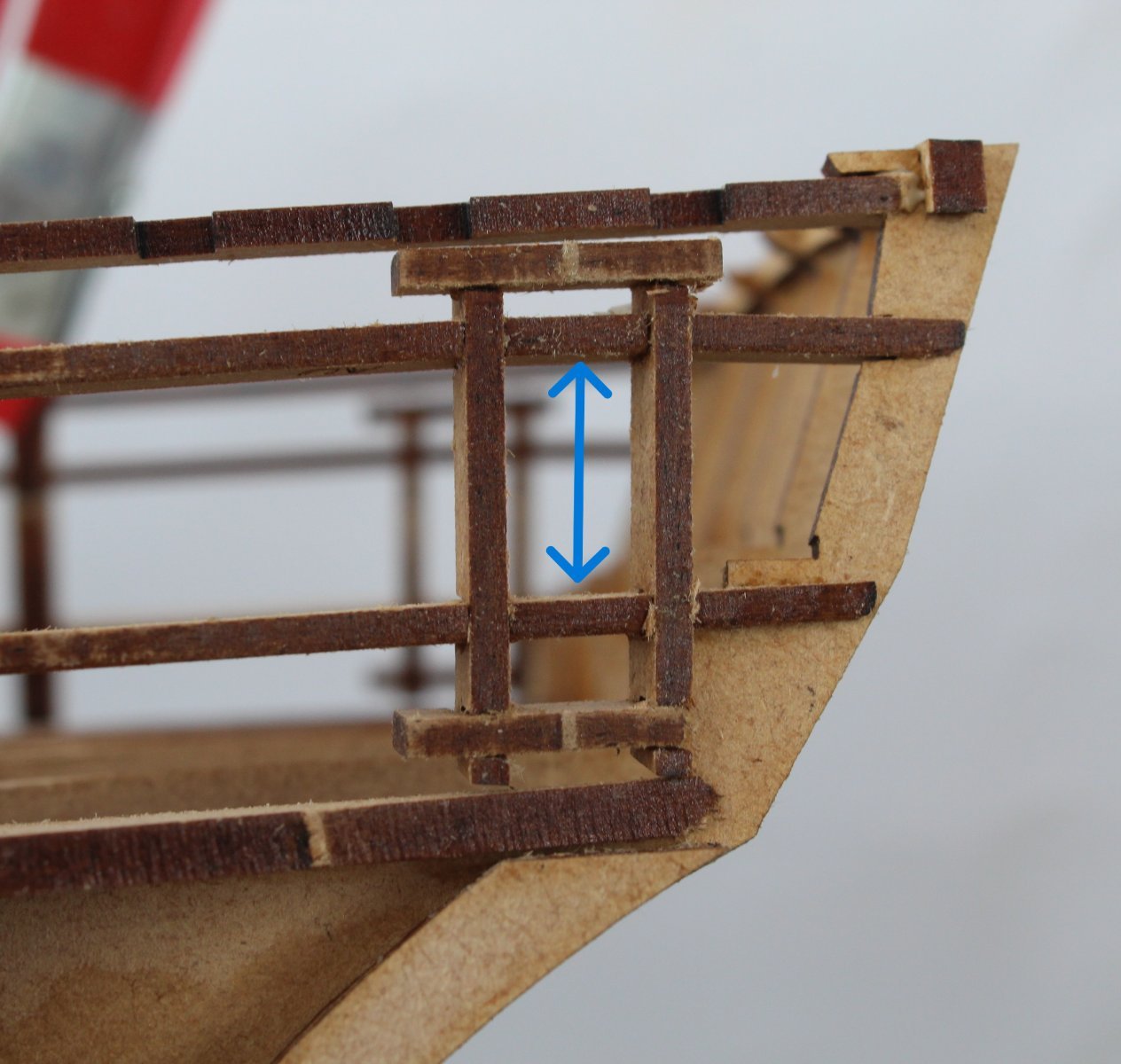
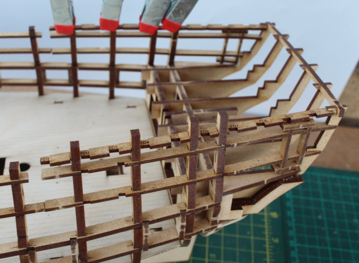
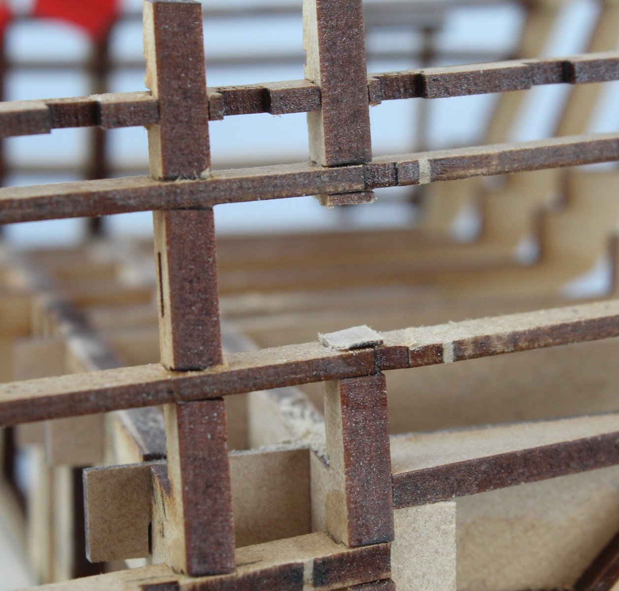
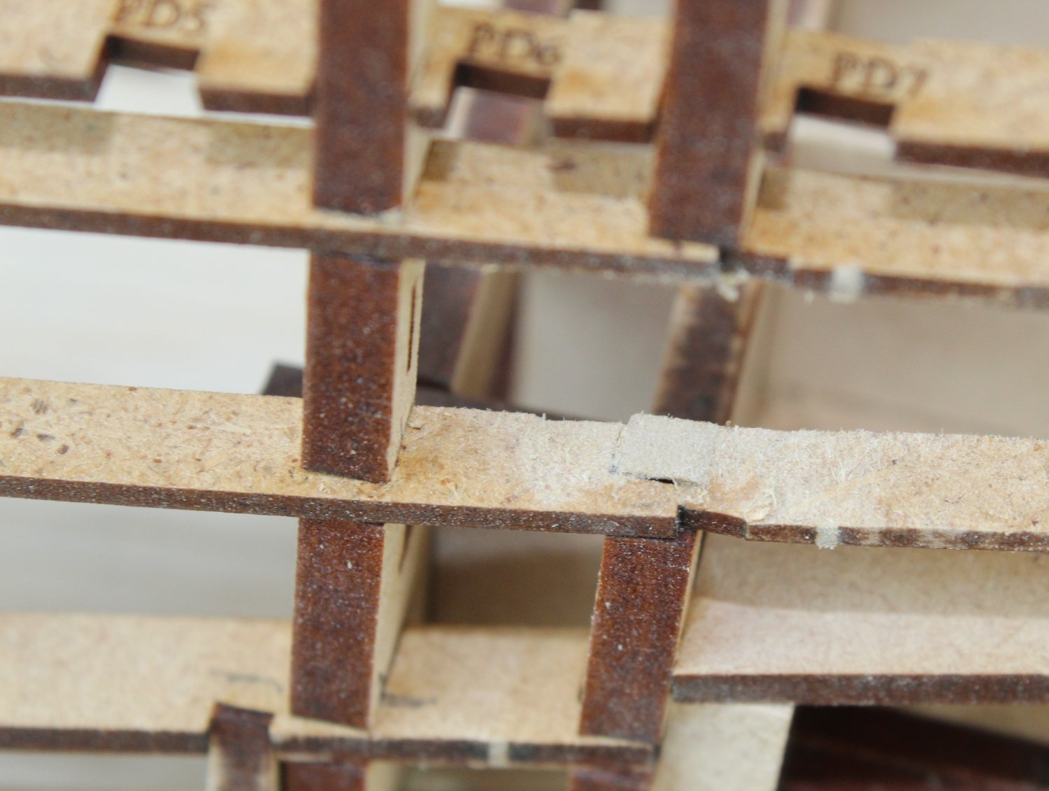
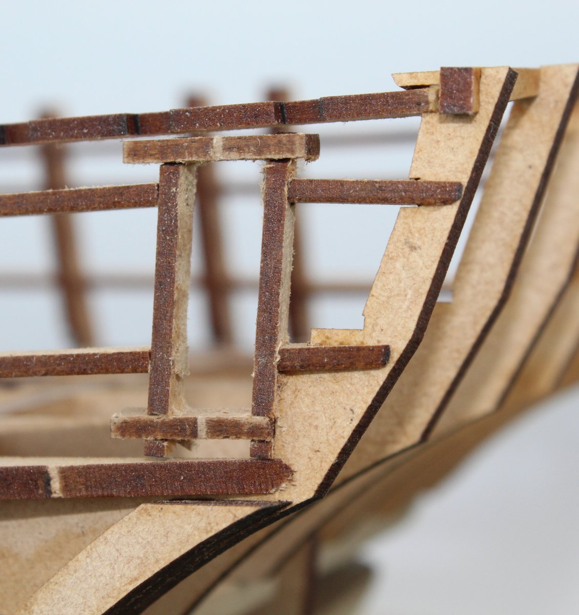
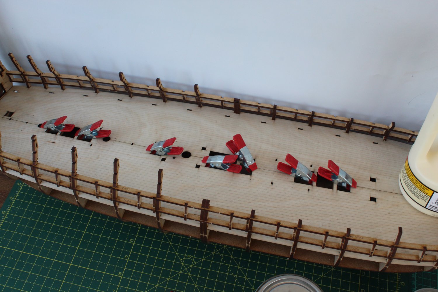
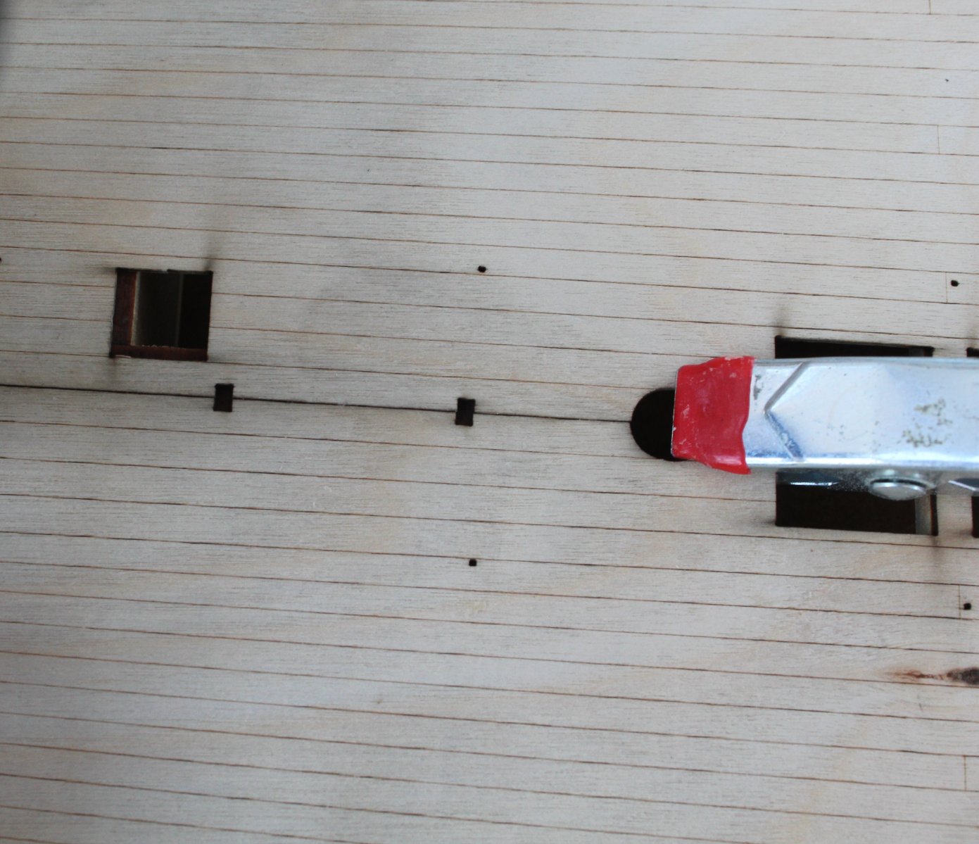
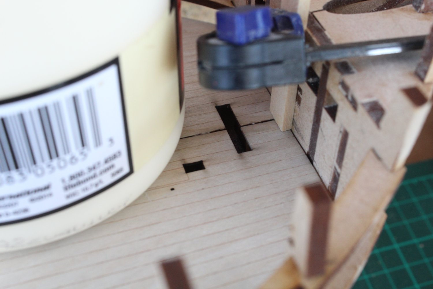
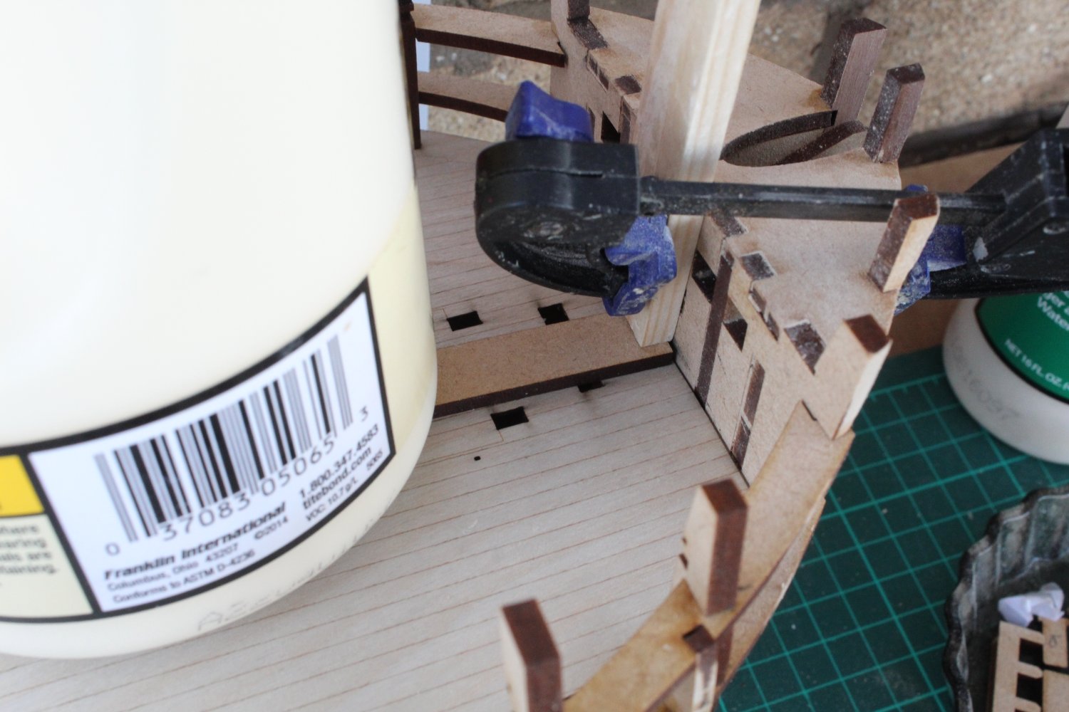
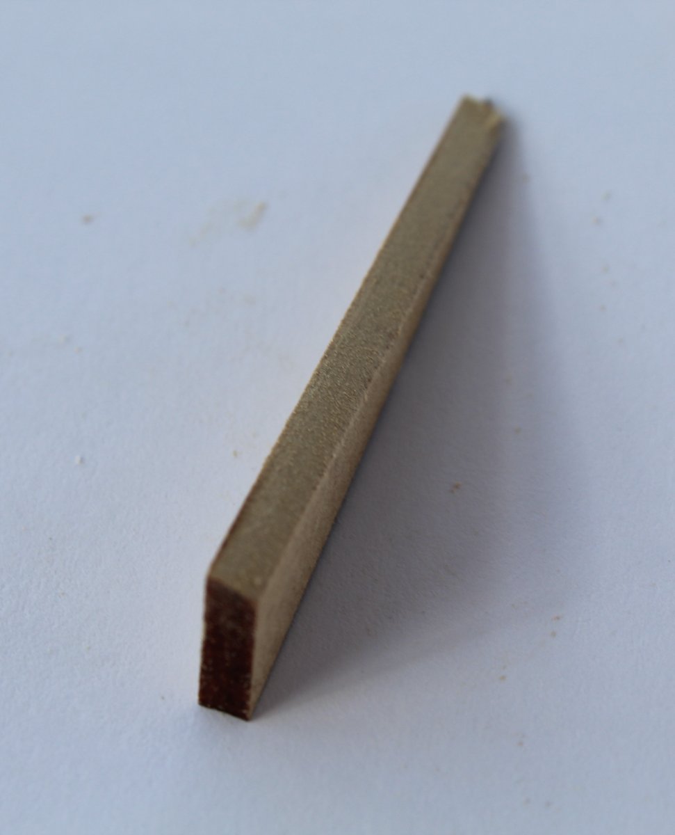
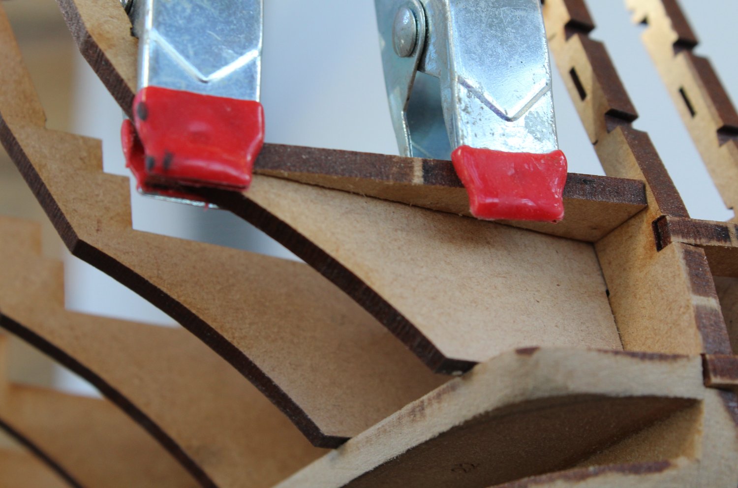
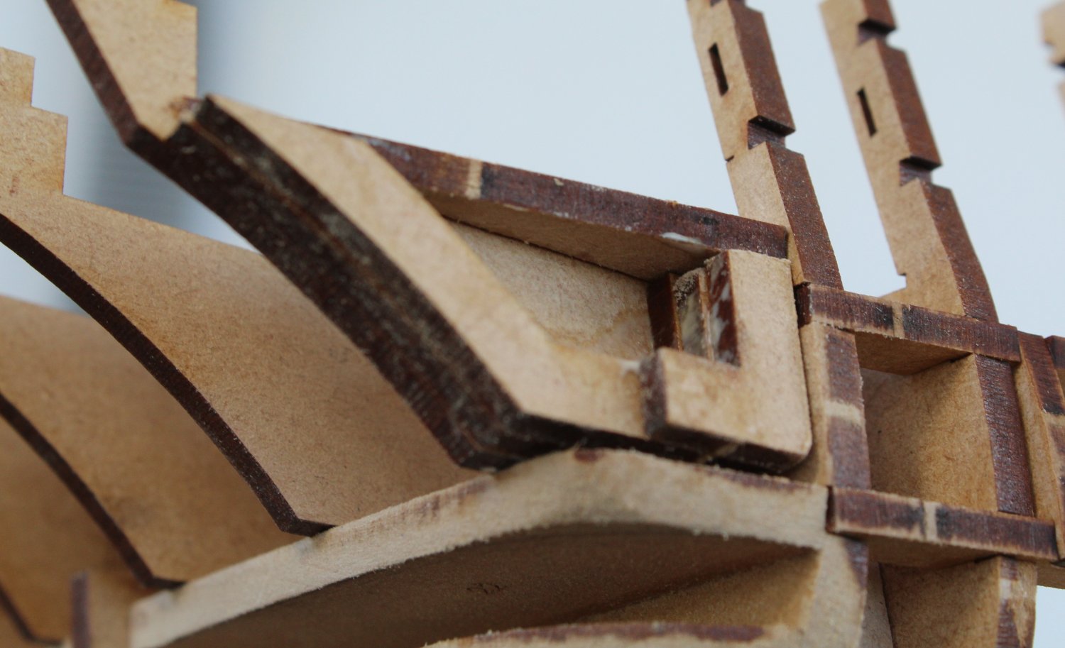
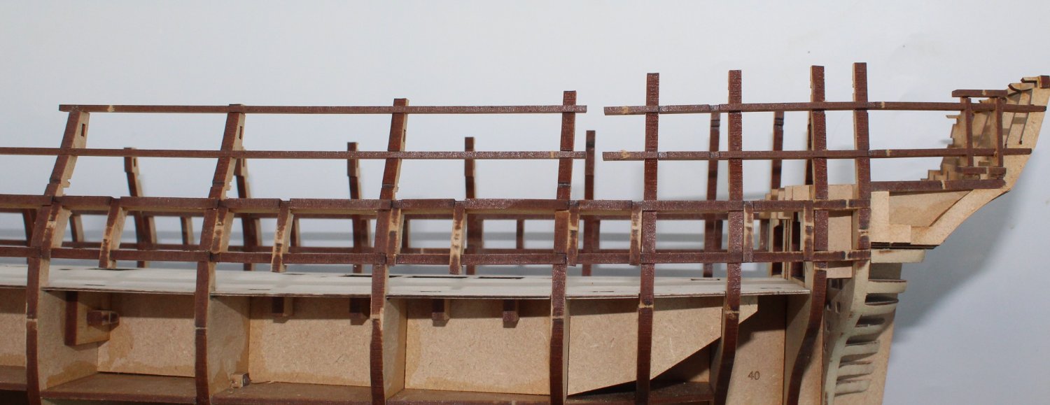
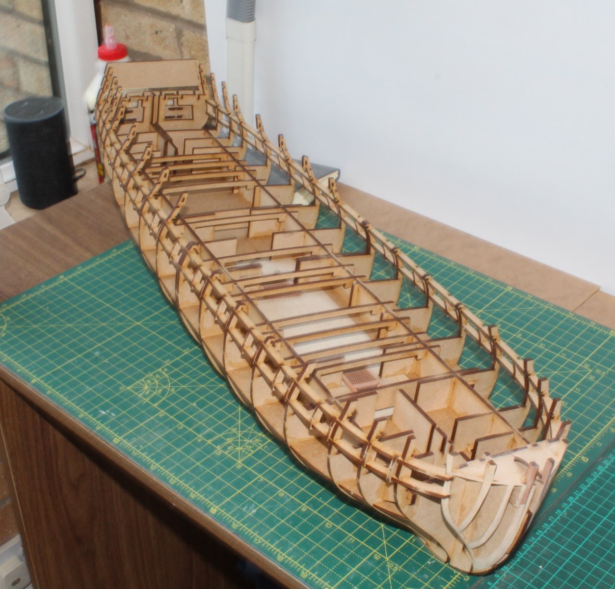
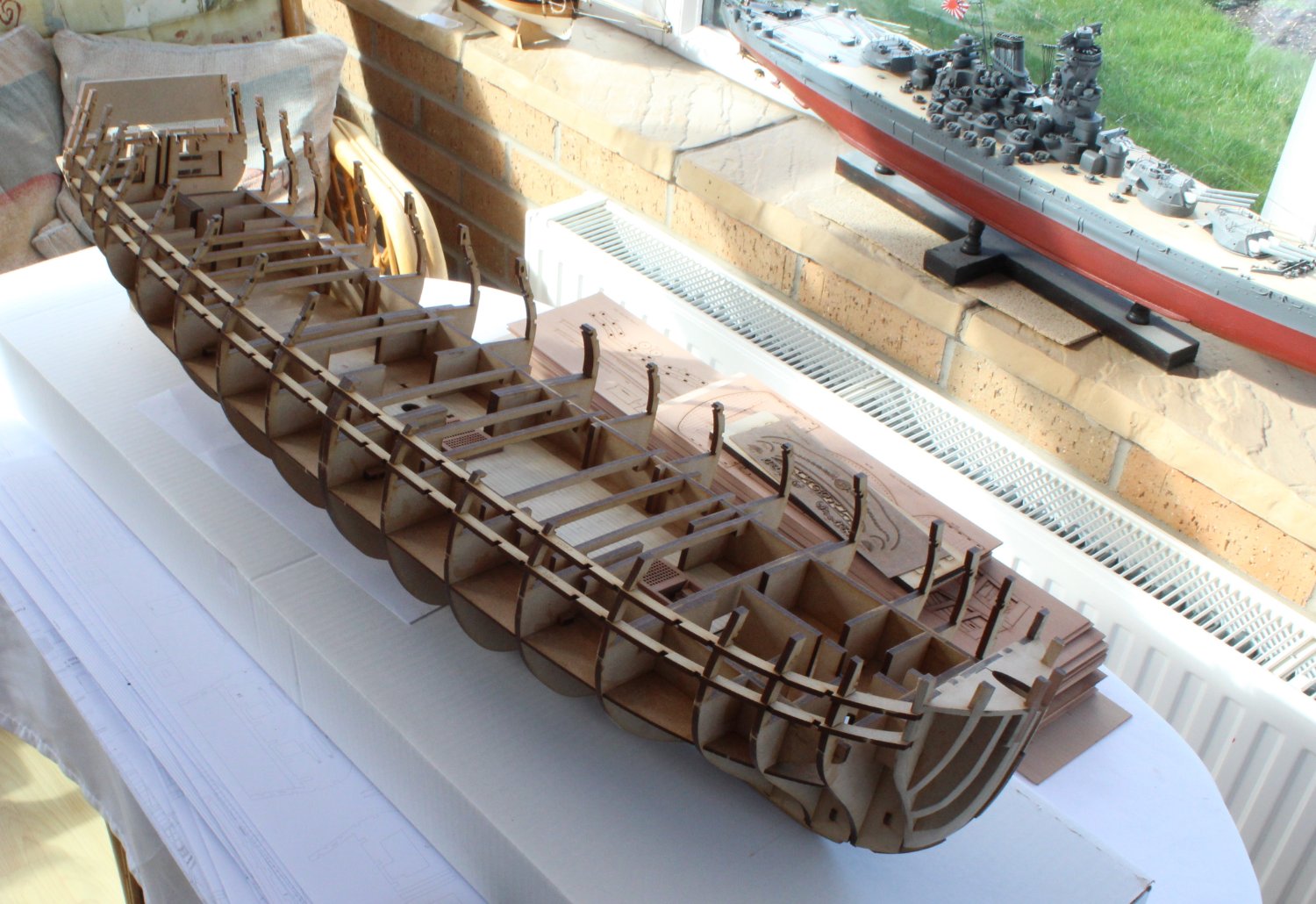
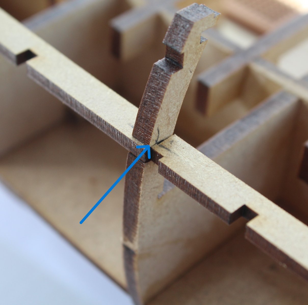
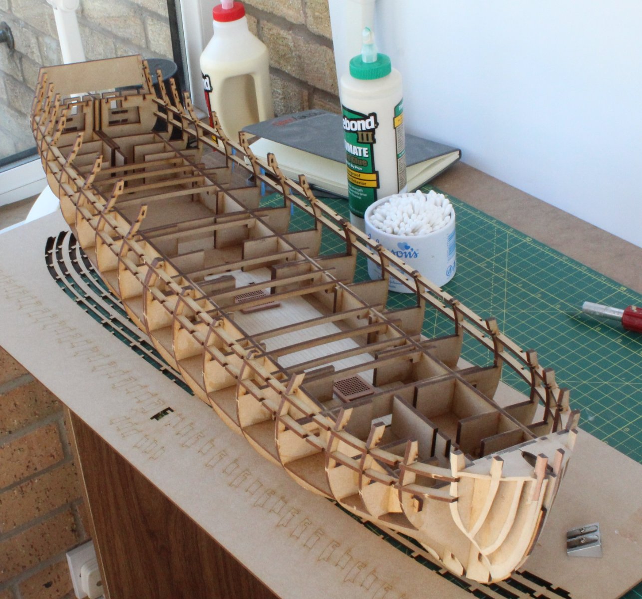
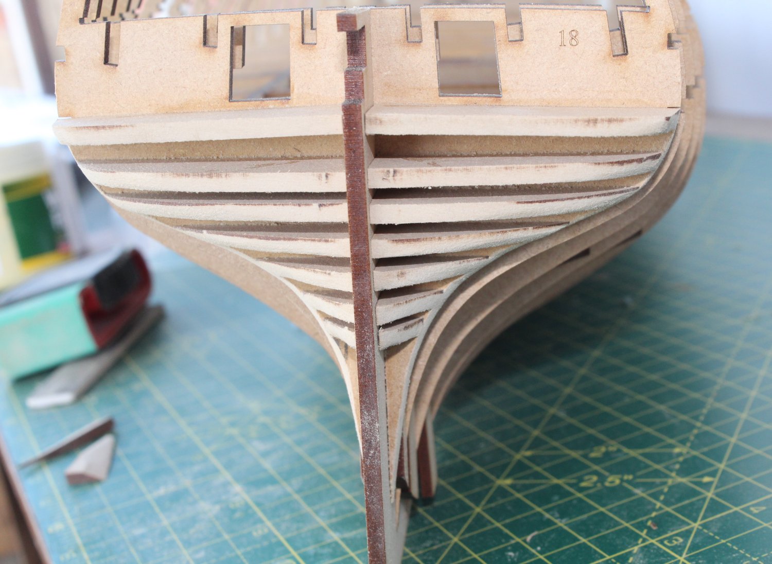
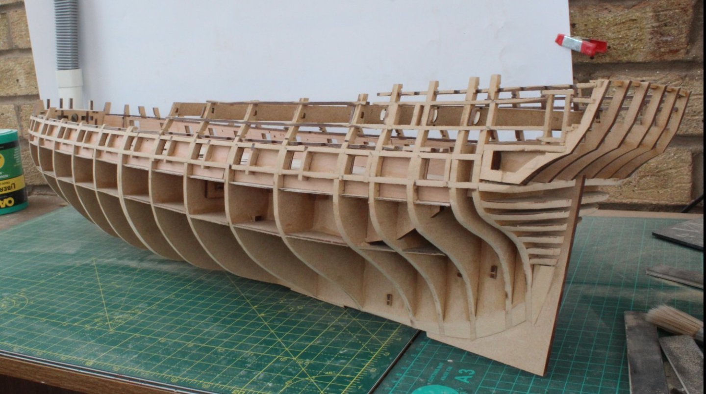
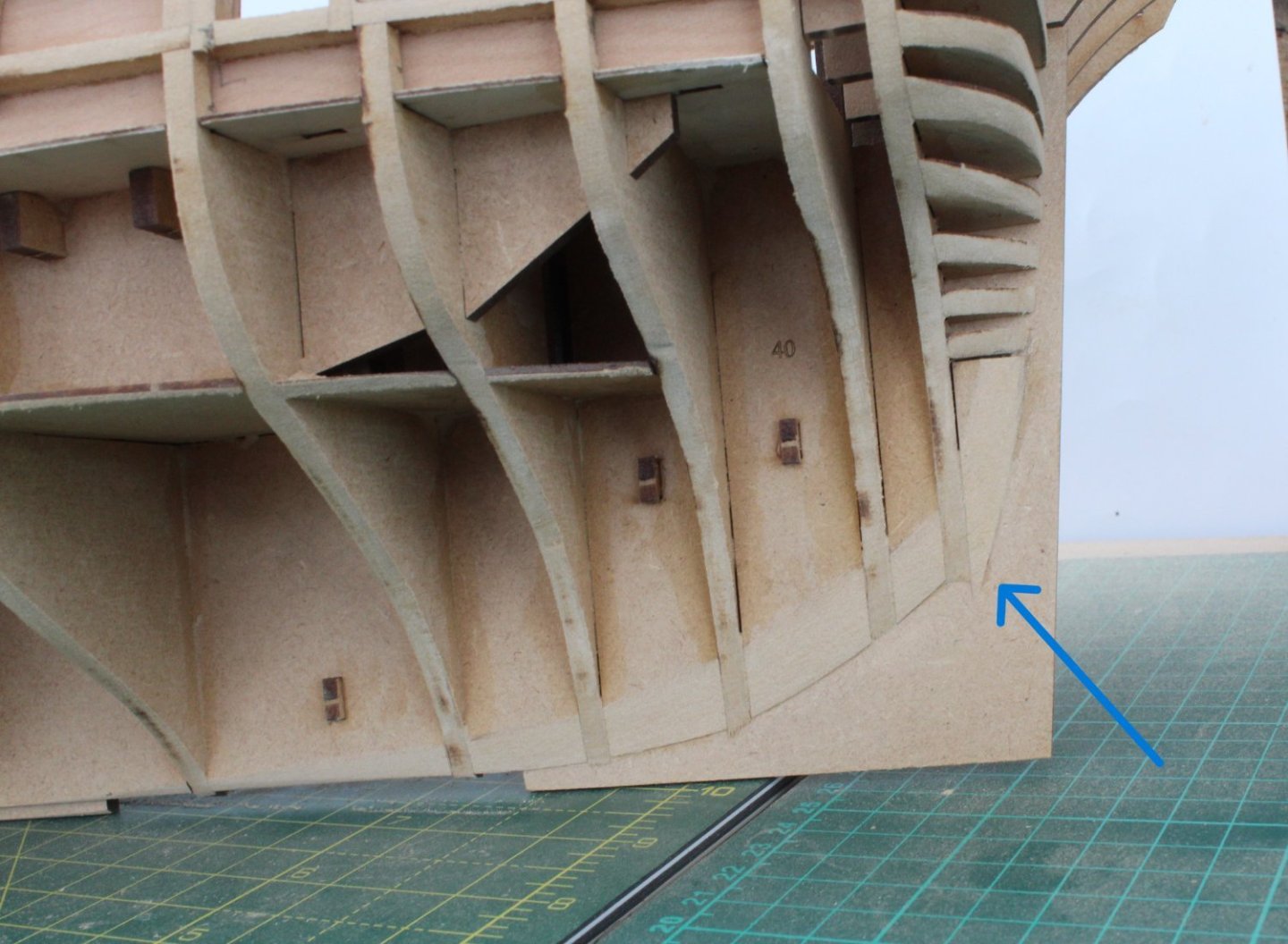
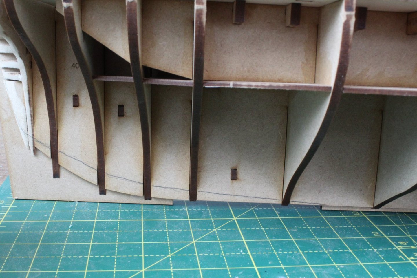
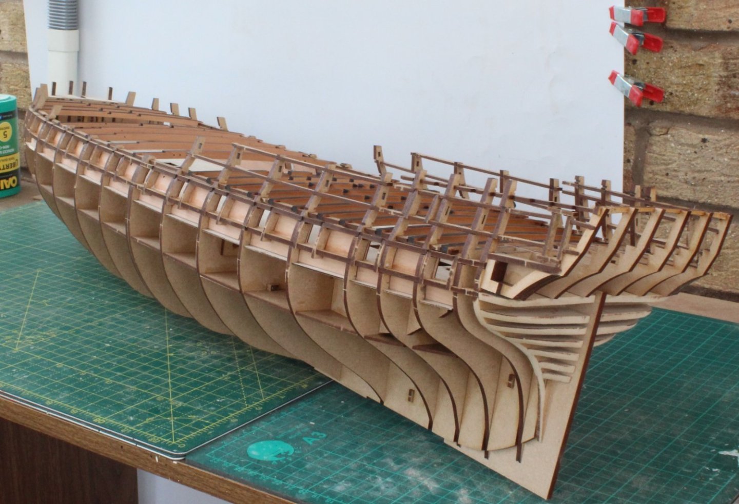
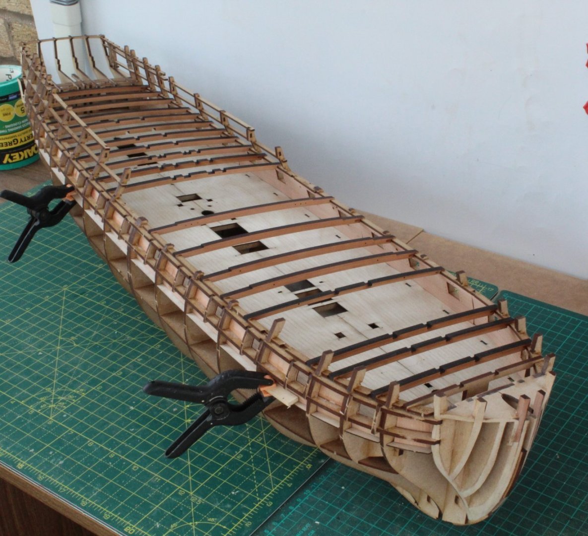
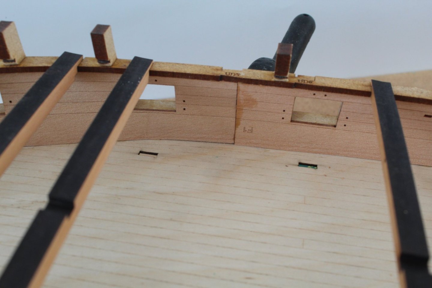
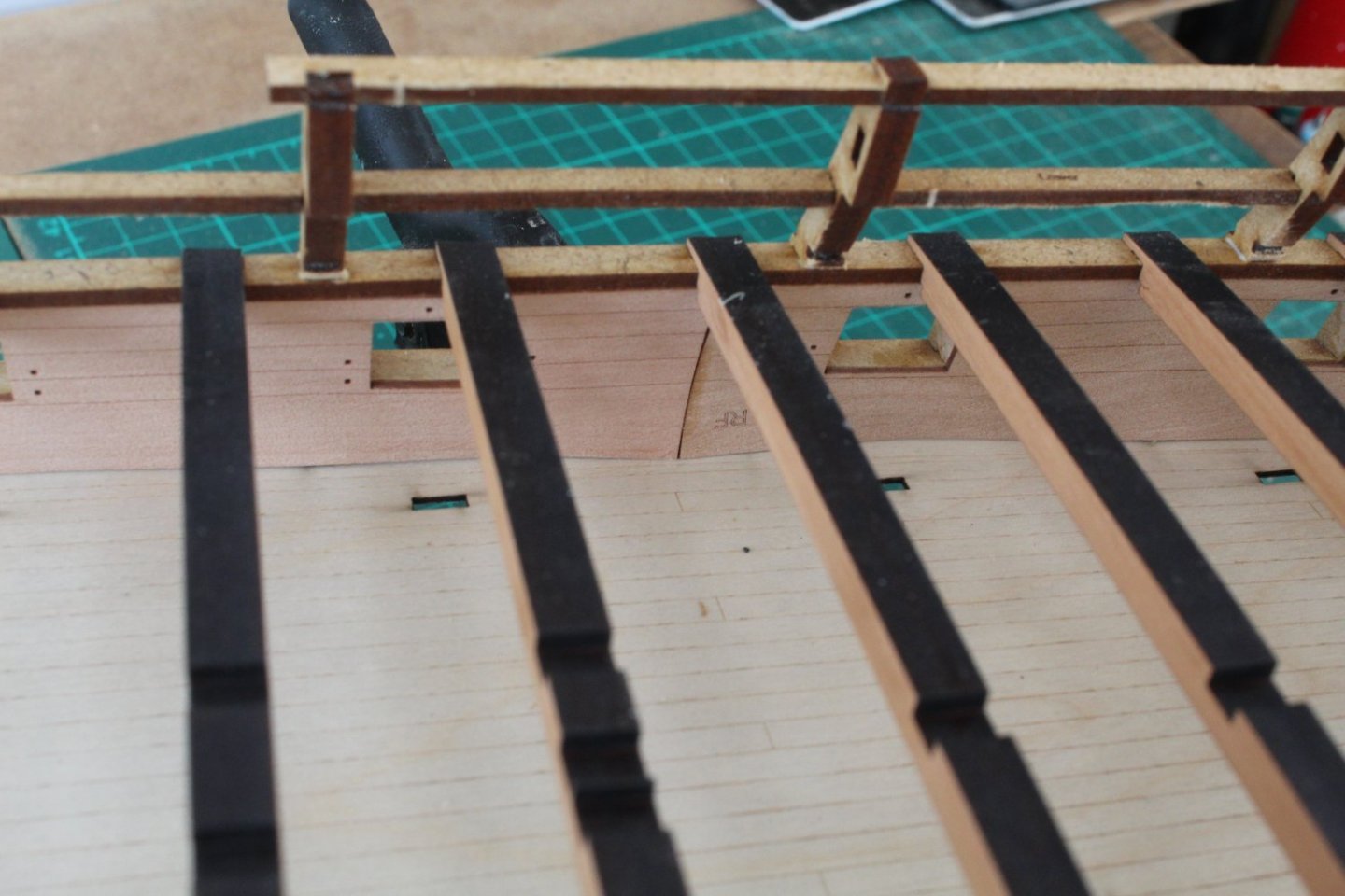
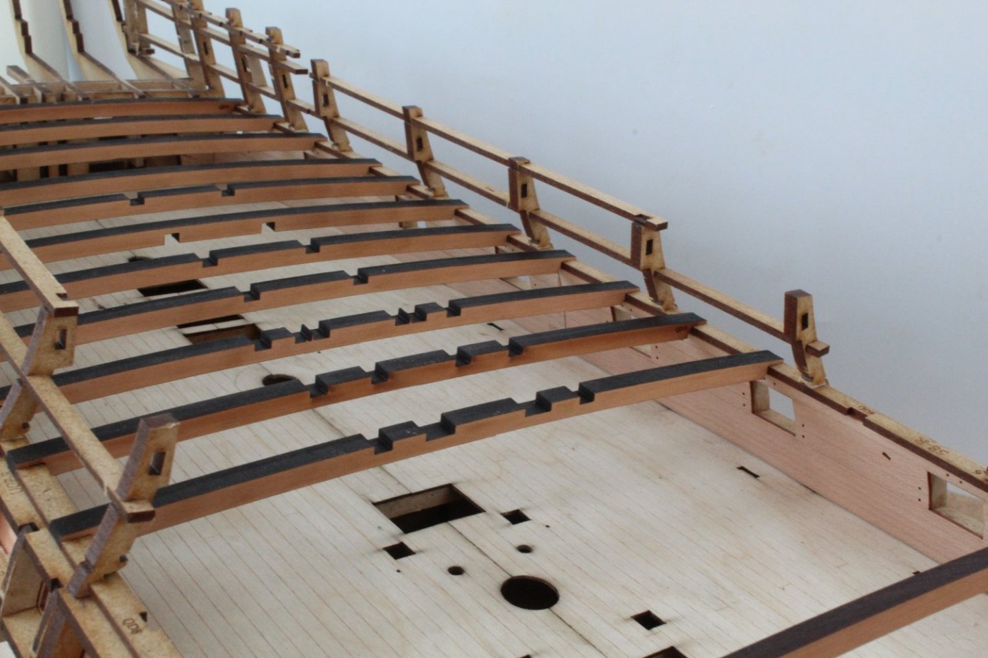
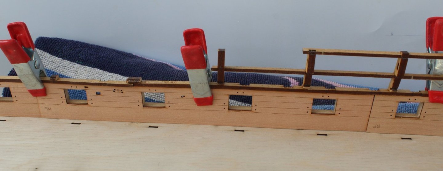
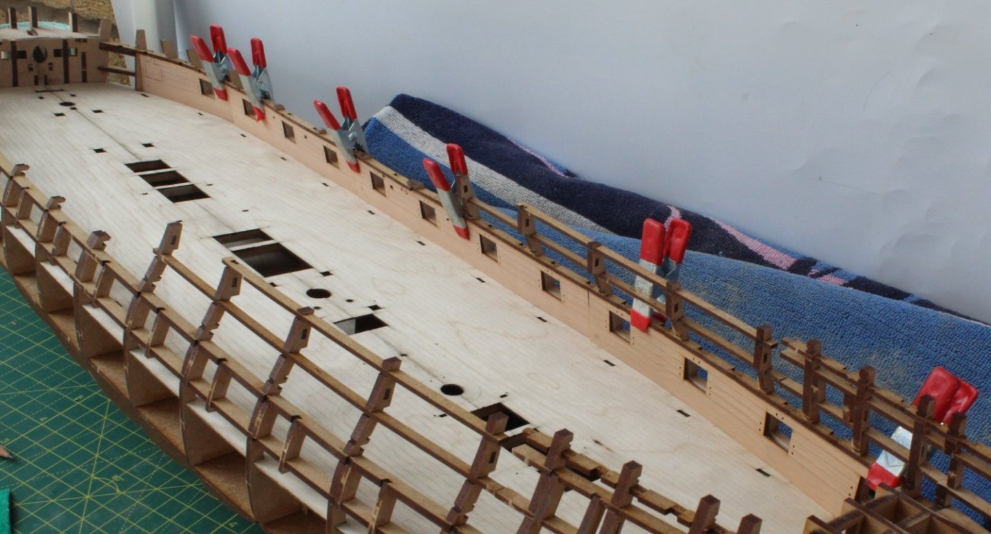
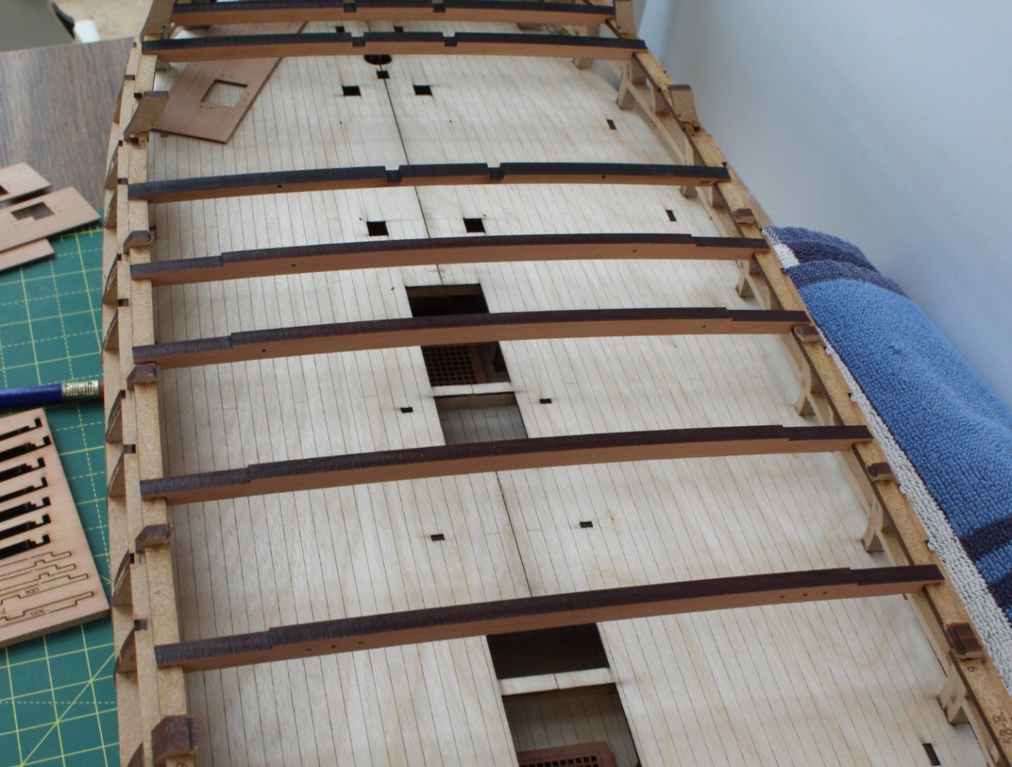
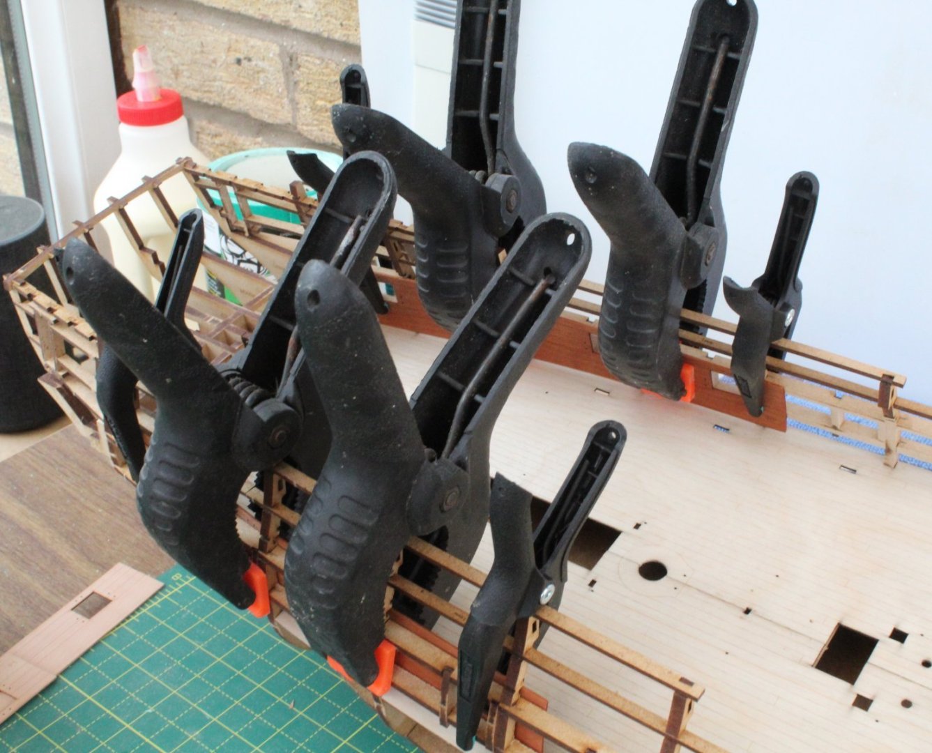
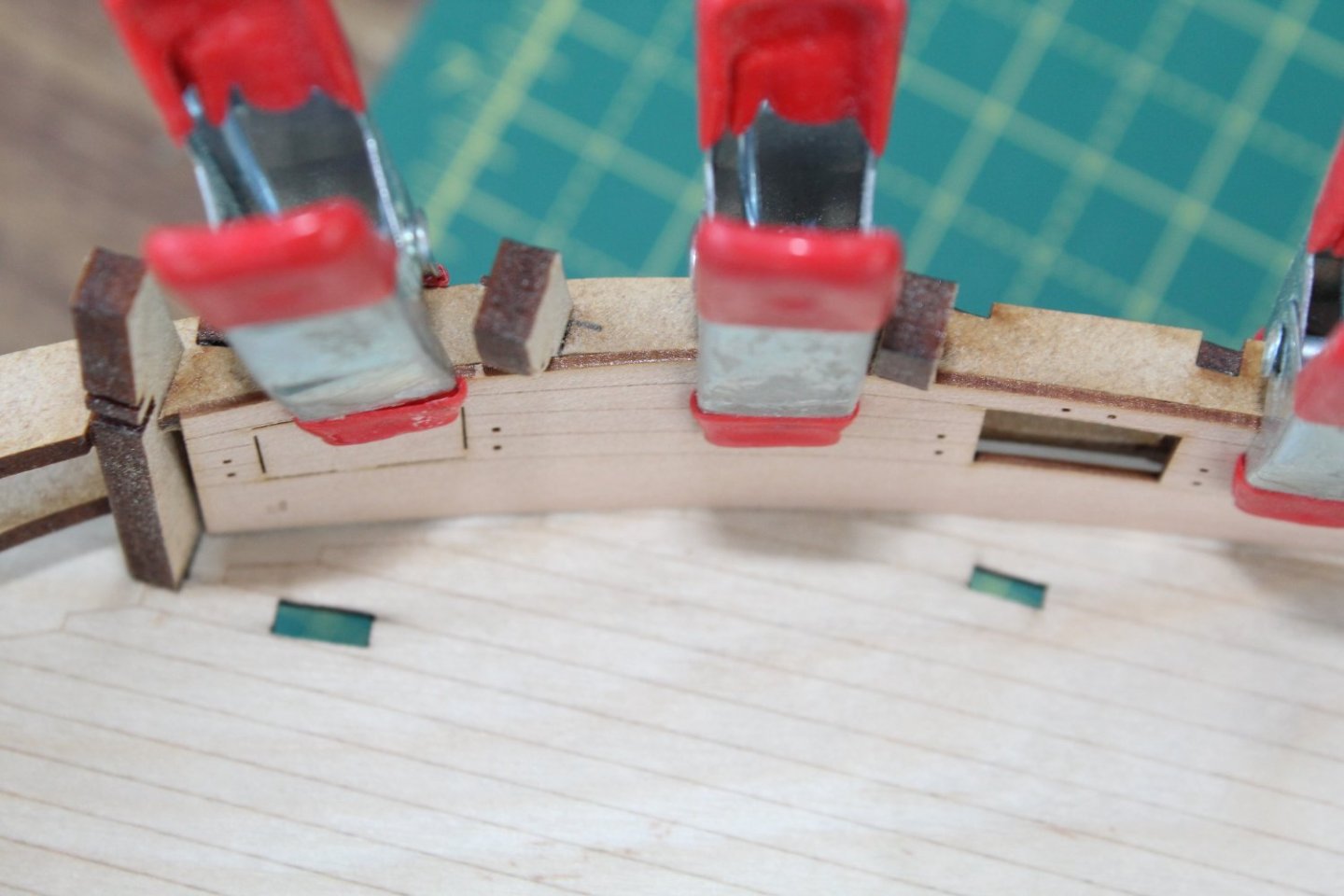
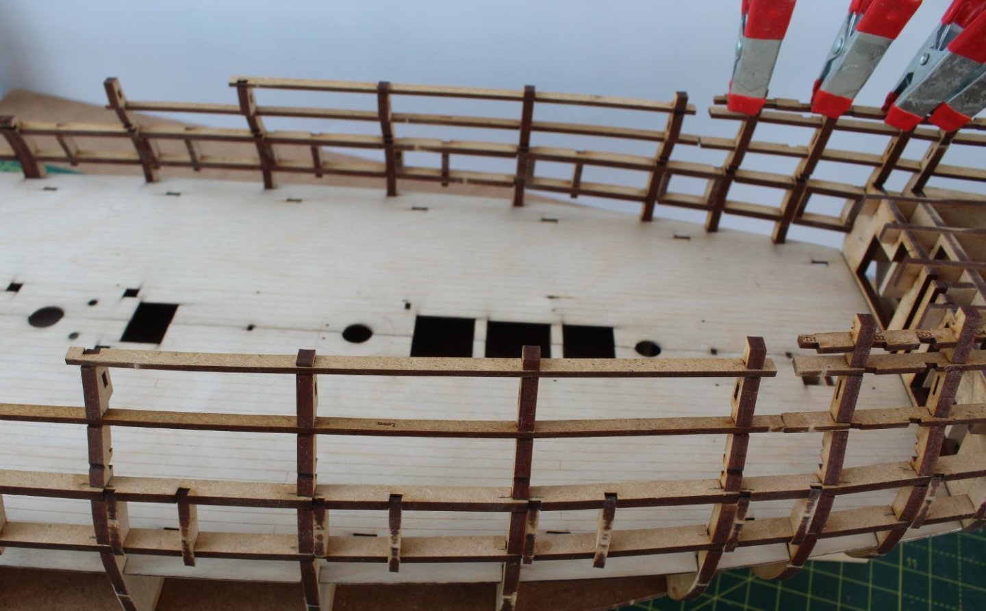
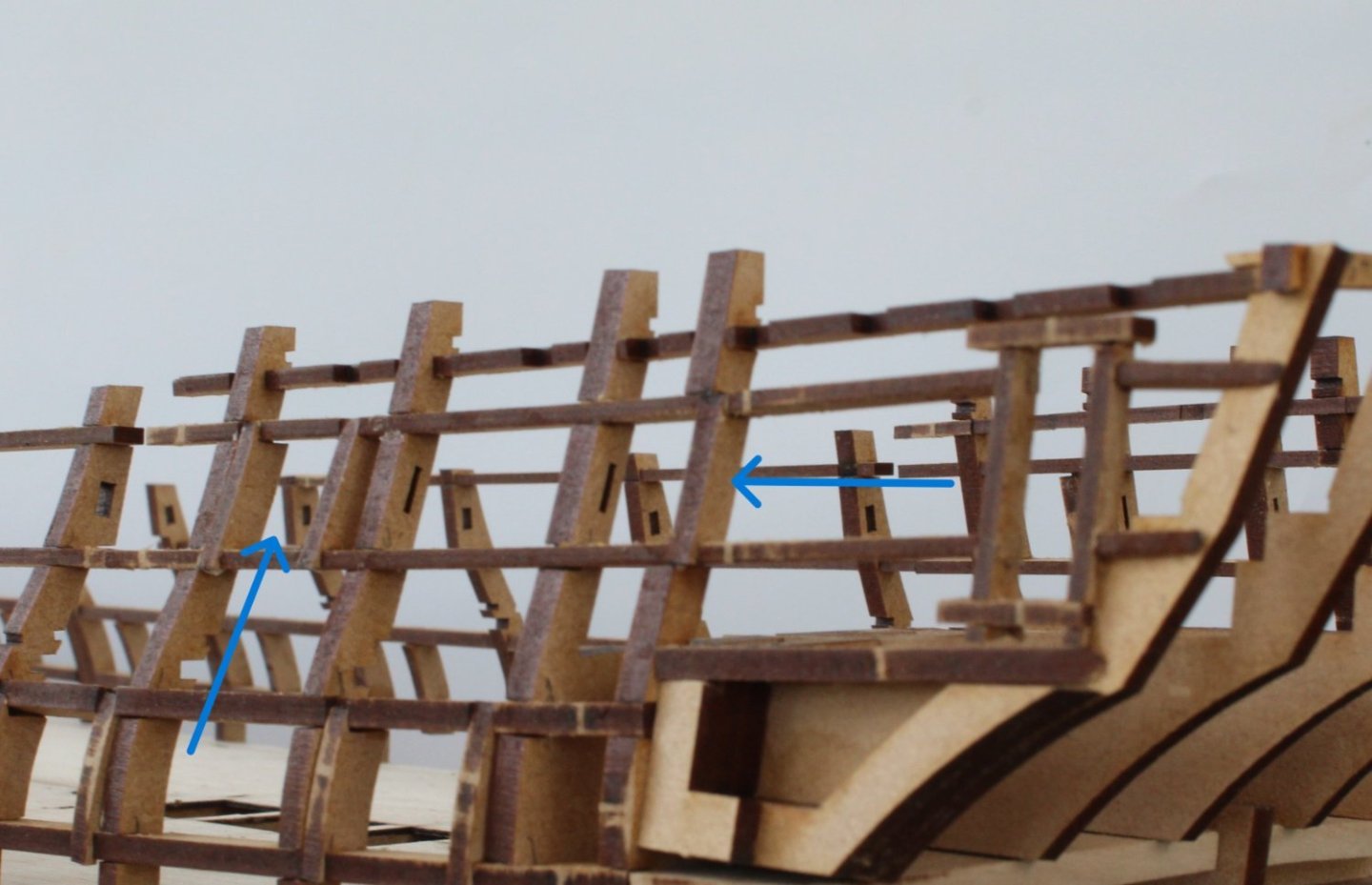
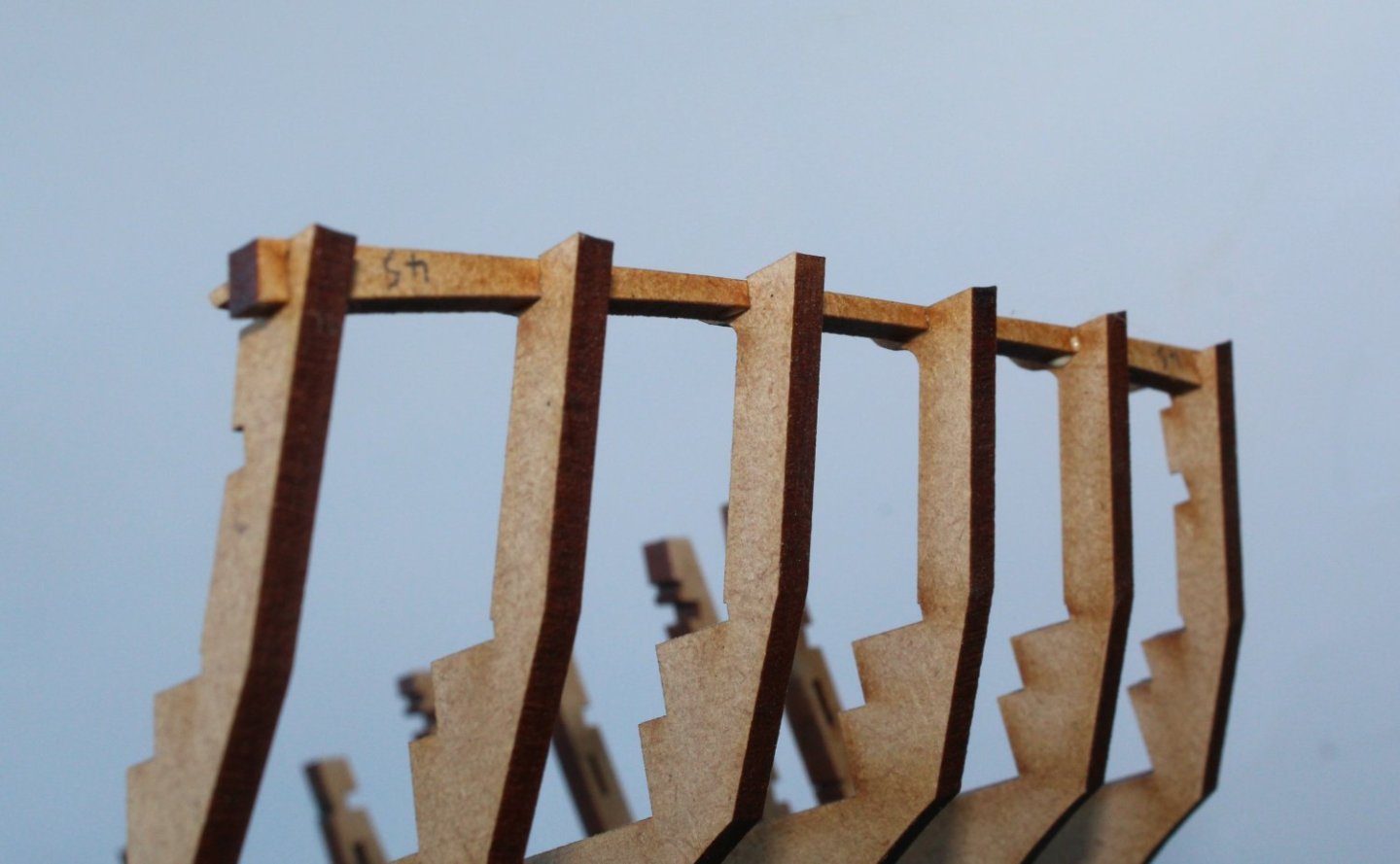
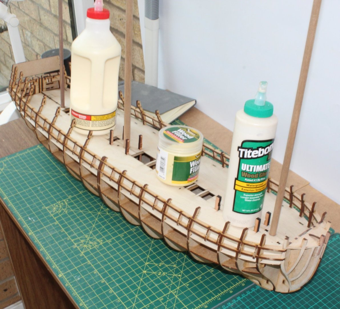
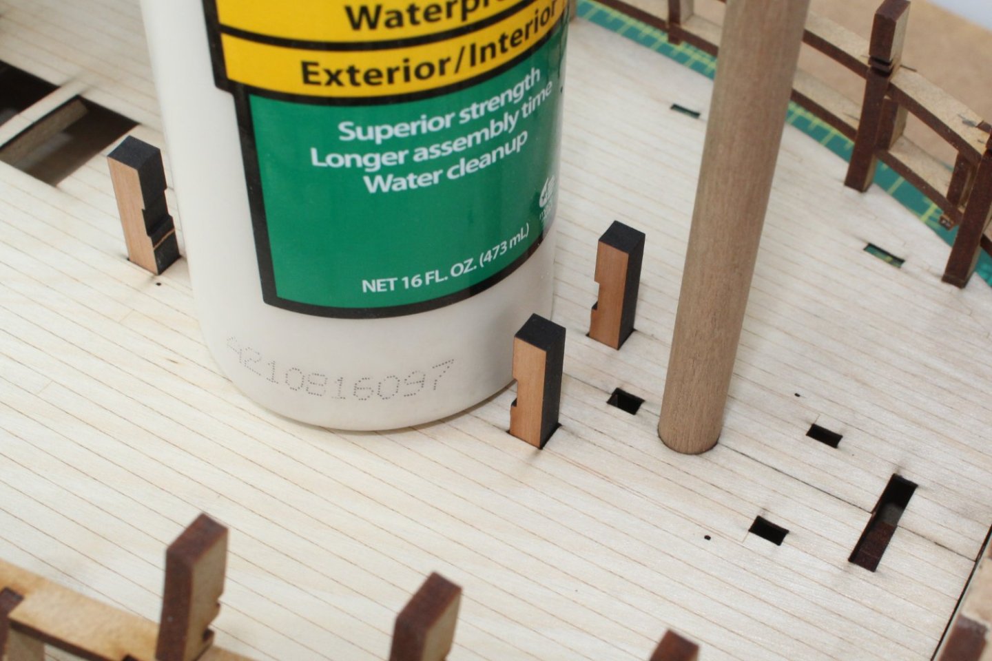
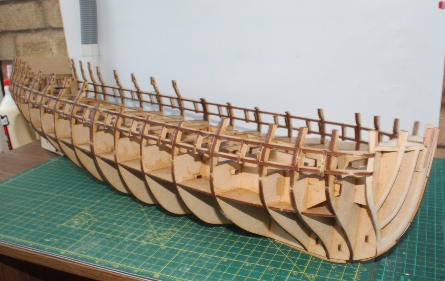
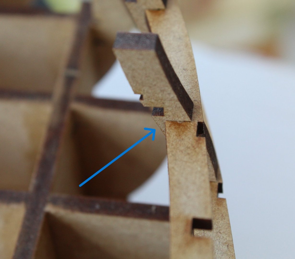
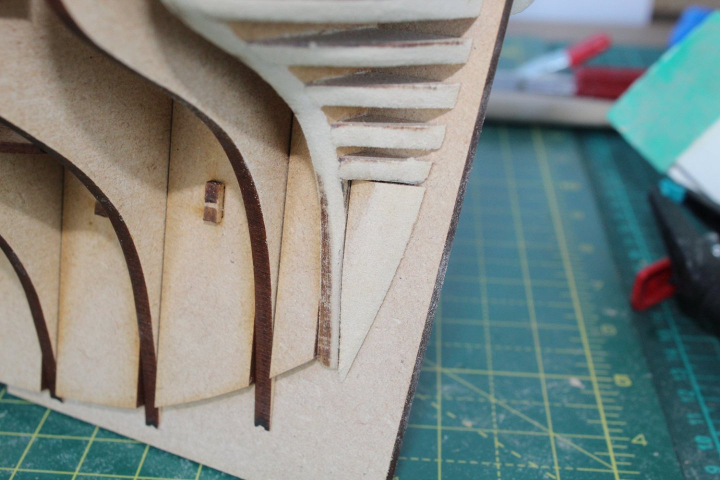
 Fairing The Hull - WIP The hull fairing process is progressing well, albeit slowly. I am finding it better to do this is short stints due to the amount of sawdust that is being generated. The task has been made much easier with the aid of a palm sander which I am using in conjunction with my Amati sanding block (A7140) both fitted with 80-grit sandpaper. I am also using sandpaper and sanding sticks primarily to remove the laser char from the bulkhead ears. After a few hours work yesterday I finally completed the fairing of the left-hand side, but I know there are a couple of areas which may need a bit more work before I start adding the first planking layer as can be seen with the blue arrow in the second photo. I am pleased with how the left side quarter gallery upper finishing canopy and quarterdeck outer bulwark patterns are looking when I did a dry fit. The forecastle bulwark pattern will need to be soaked and clamped which will done once hull fairing process is complete. I have now started fairing the right-hand side. I am finding it easier, for this side, to work from stern to bow. I have completed fairing the upper section where the quarter gallery upper finishing canopy and quarterdeck outer bulwark patterns will fit. Some of the essential fairing tools can be seen in the previous two photos. I will continue to fair the upper section around the bow before moving down to the lower hull sections. My shipyard time will be limited as I have tickets for one of tomorrow's FA cup games which wipes out Sunday and I will be watching the six nations rugby matches this afternoon and evening.


- 587 replies
-
- 16
-

-
- Indefatigable
- Vanguard Models
- (and 1 more)
-
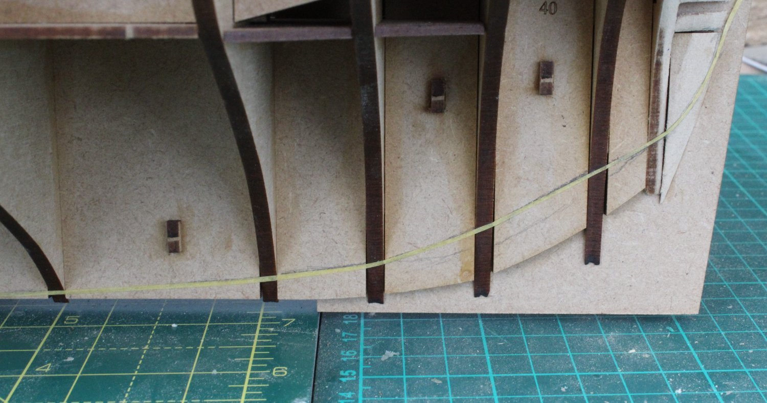
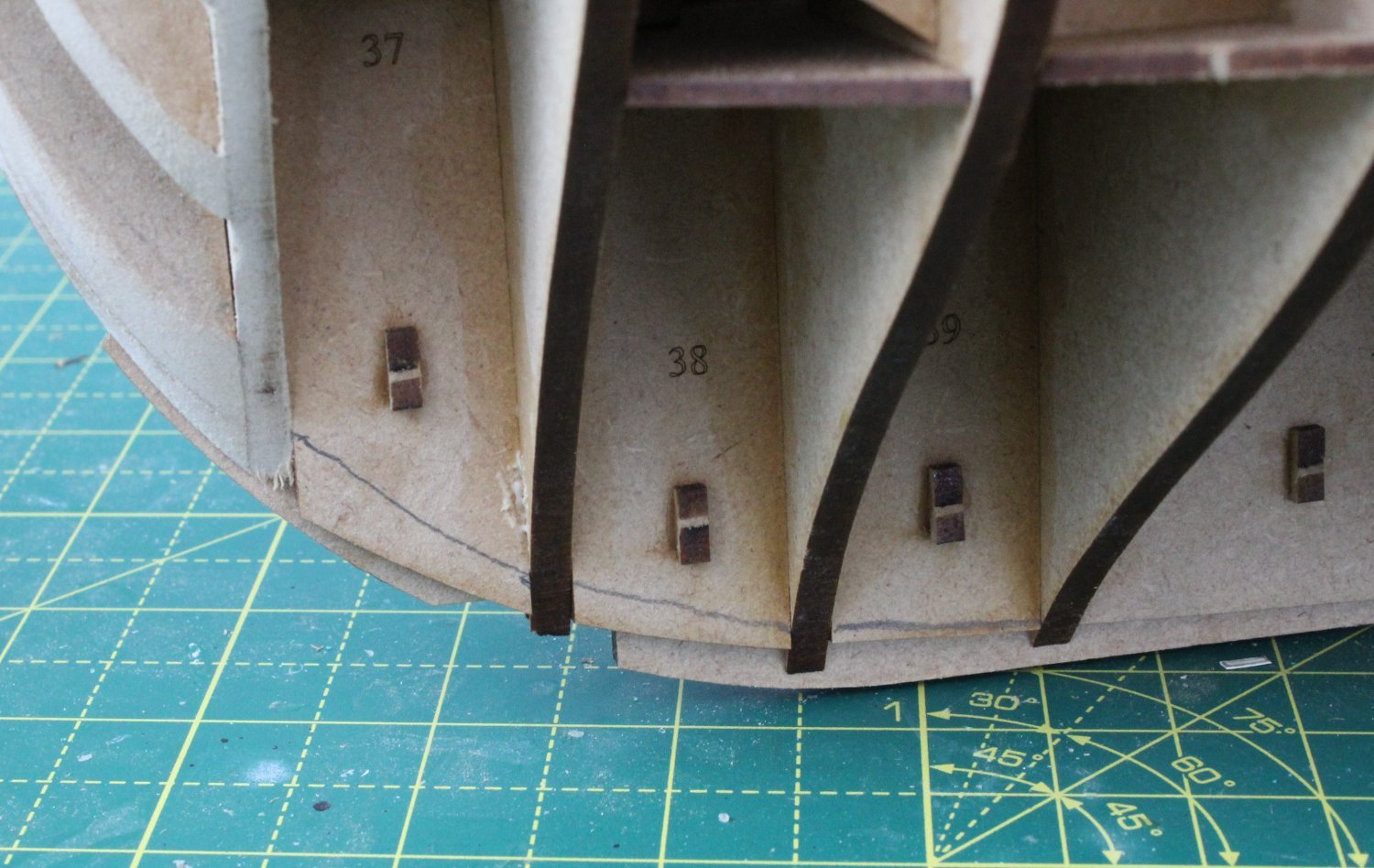
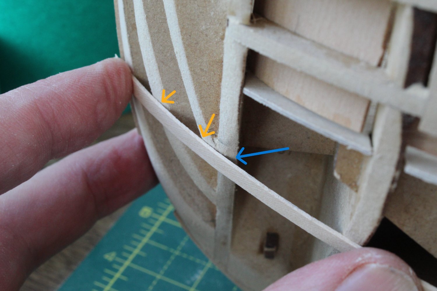
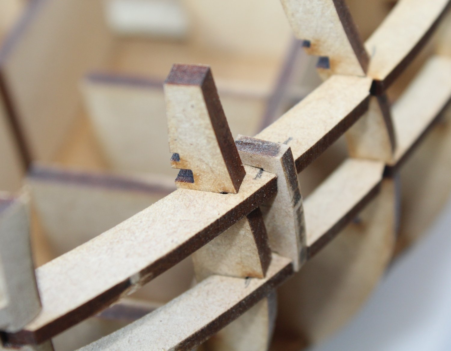
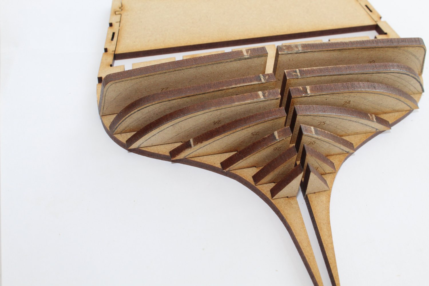
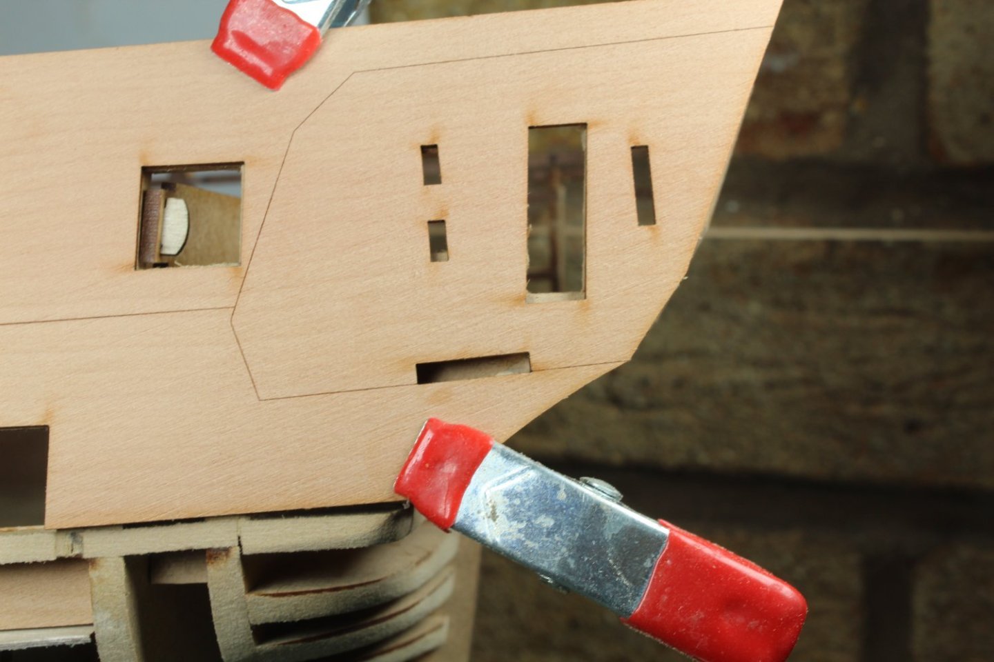
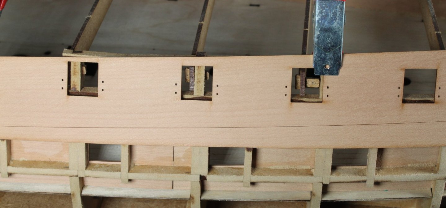
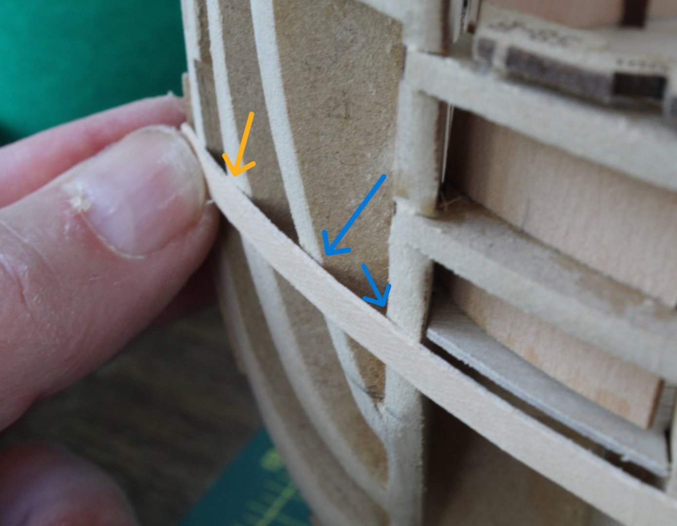
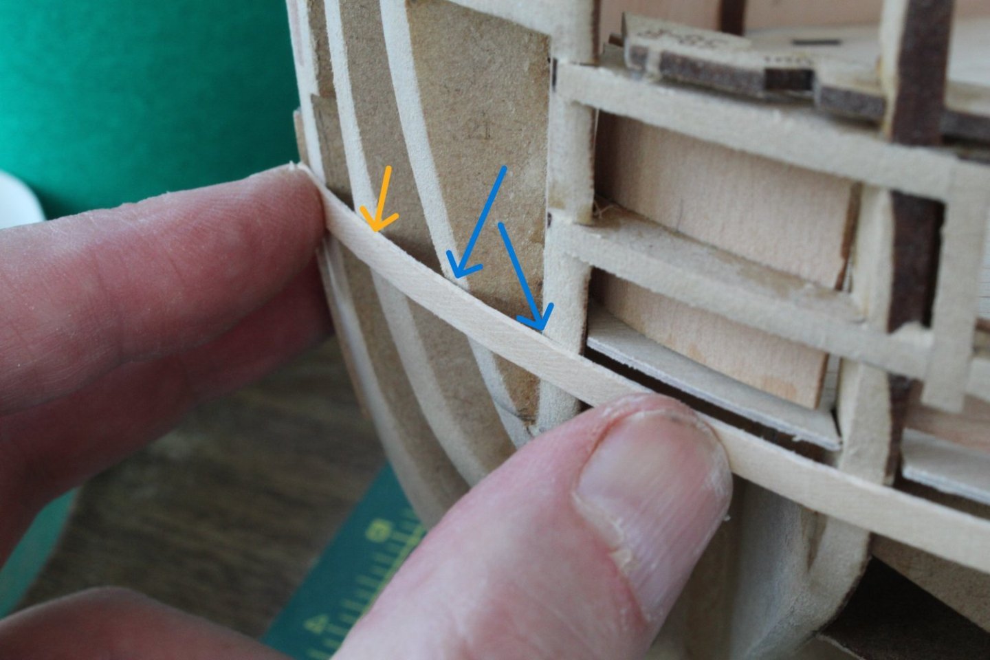
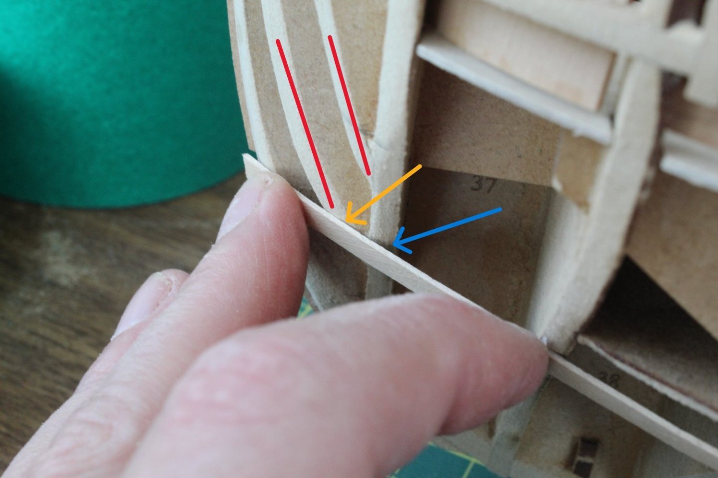
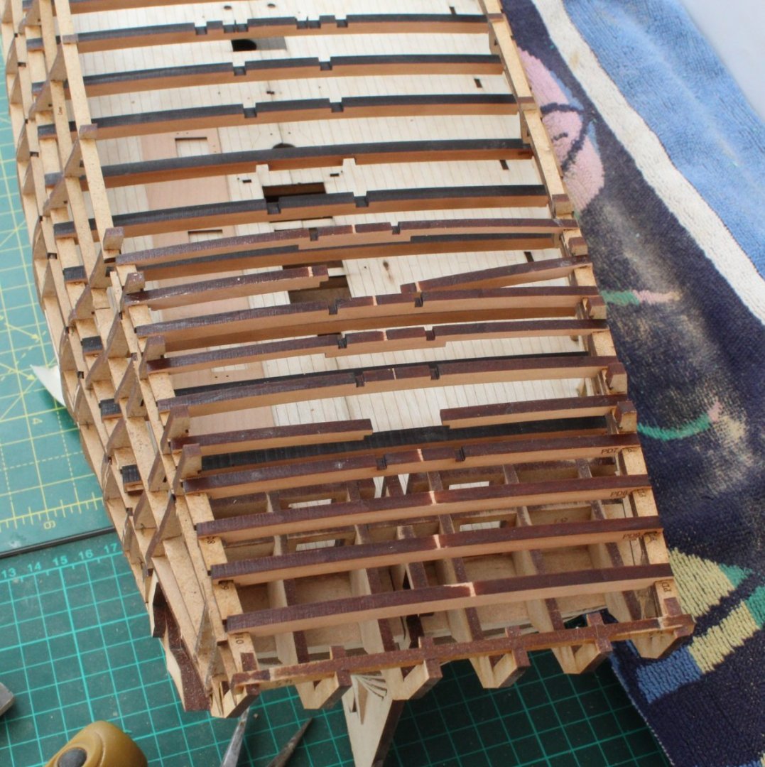
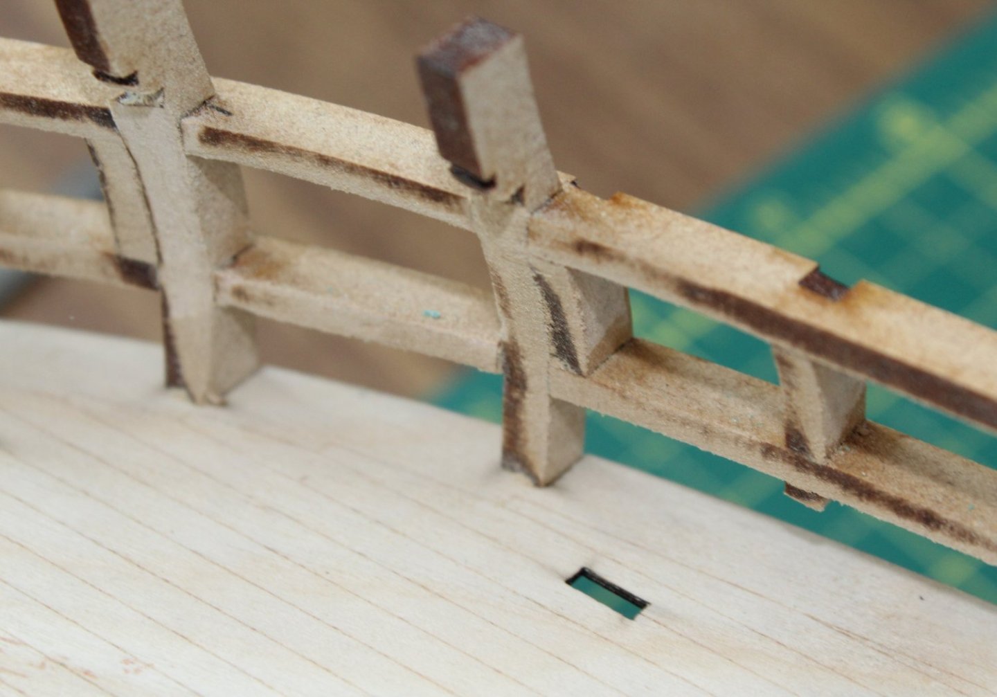
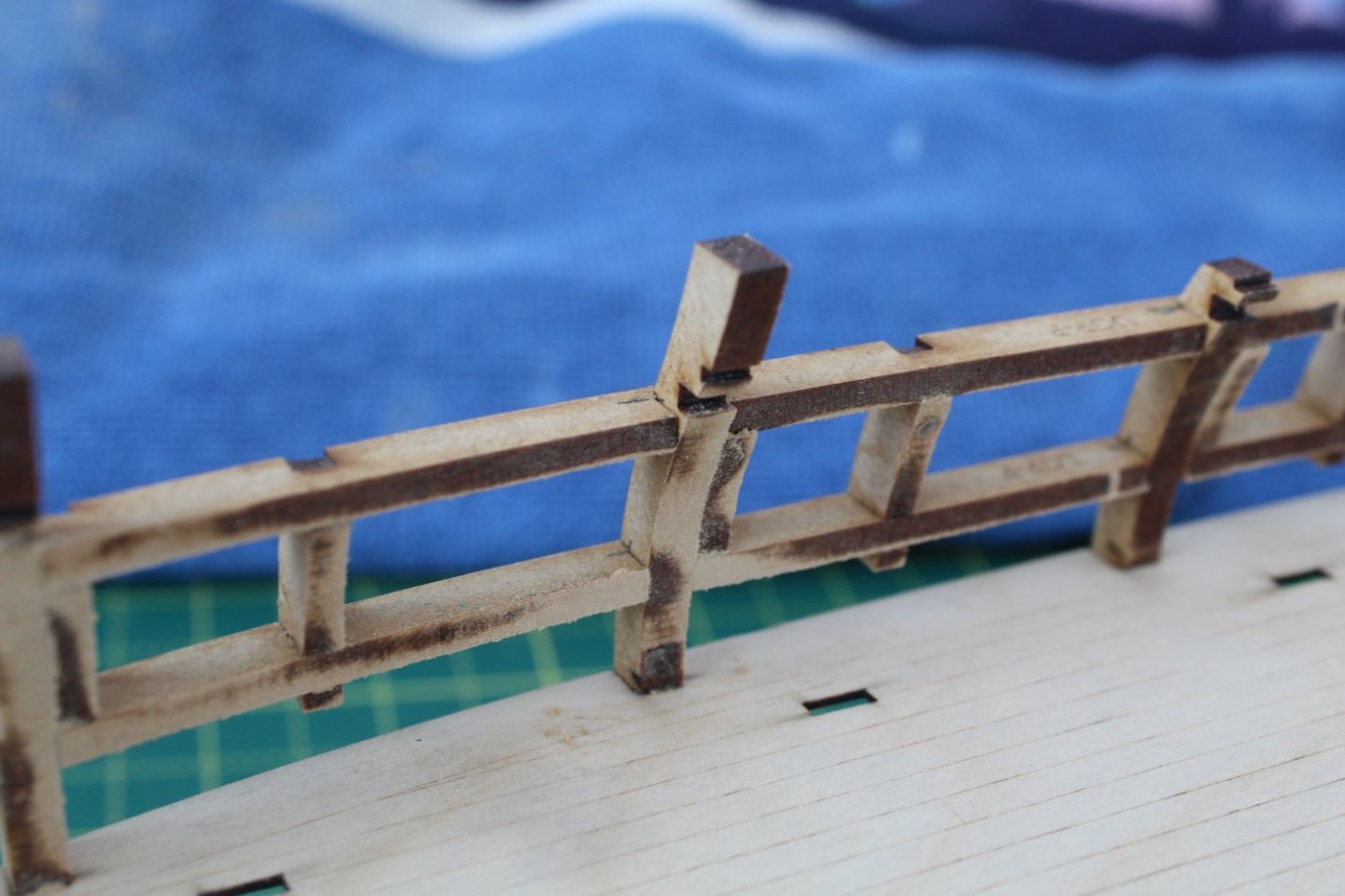
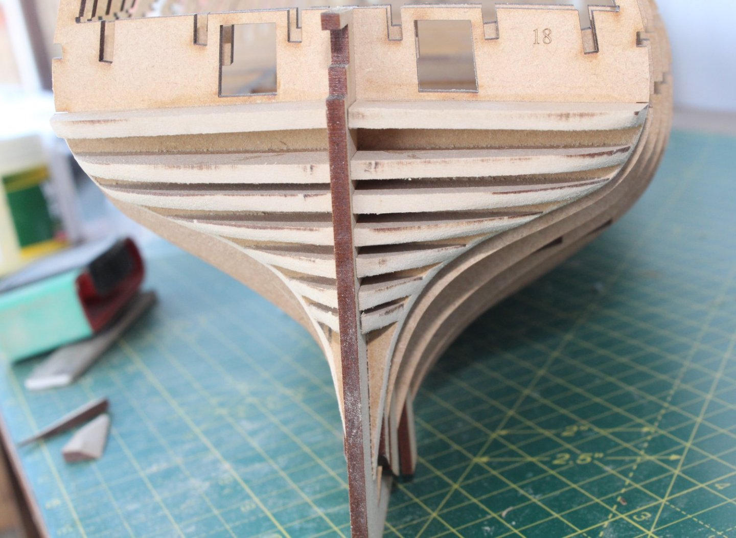
Fairing The Hull When I first started modelling and built AL’s Scottish Maid and then Caldercraft’s HMS Victory I followed the method detailed in the simple hull planking techniques document and drew a beading line and then tapered the keel to the edge to account for the additional thickness when the 1st and 2nd planking had been completed. Since then, I have followed the method shown in several of Jim’s build logs which is to terminate the 1st planking at around the stern’s beading line area thus removing the need to taper the keel. The first task was to draw on some sanding guide lines for the stern and bow fillers. You will note in one of the attached photo’s I used some 1mm masking tape to check the position of the beading line. With my new palm sander raring to go I have started to fair the hull and I am working from the bow toward the stern, currently at the midpoint along the left-hand side of the hull and for the most part everything looks good. This is task that cannot be rushed and I am checking to see how the planks are laying over the bulkheads, particularly looking for good and full contact around the curved bow area at the moment. The bow area still needs more attention as I’ve detailed in the attached series of photo’s where I am moving a plank down the bow to check for contact. I have added yellow arrows to indicate where I think I need to fair more so that planks will lay flat. The blue arrows indicate where the planks are not fully flush with the bulkhead(s). In the final photo I have indicated, with the red lines, where I think more fairing is needed. I would welcome any advice to ensure I get this aspect right especially if you think I am wrong with what needs to be done to enable the planks to sit flush.


- 587 replies
-
- 14
-
-
- Indefatigable
- Vanguard Models
- (and 1 more)
-
Hello Kevin I have just noticed, when looking at your build log, that you do not seem to have added the two stern filler parts 29 to either side of the keel under bulkhead 18, as per build steps 82 and 83. Glenn-UK
- 443 replies
-
- 4
-
-
- Indefatigable
- Vanguard Models
- (and 1 more)
-
Thanks, just preparing to start fairing the hull.
- 587 replies
-
- 2
-
-
- Indefatigable
- Vanguard Models
- (and 1 more)
-
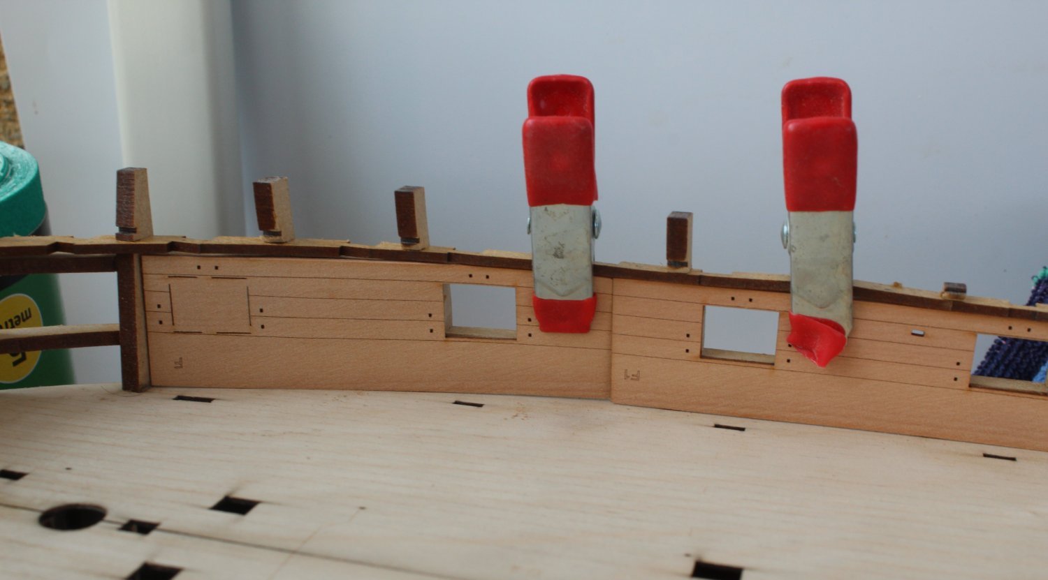
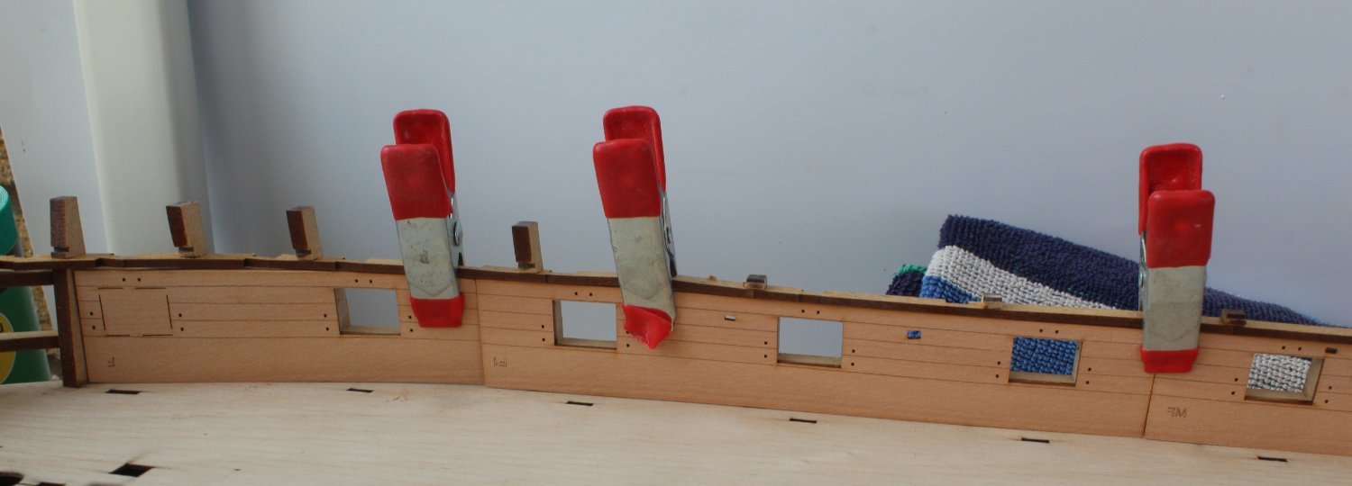
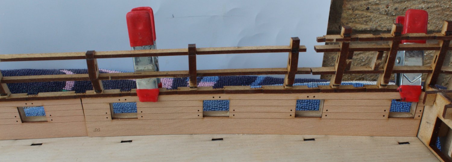
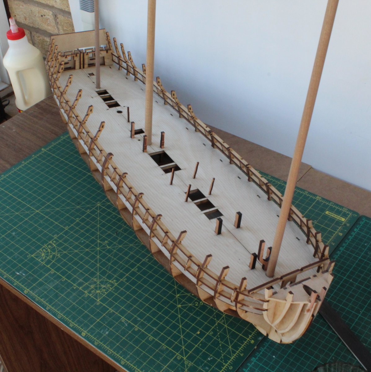
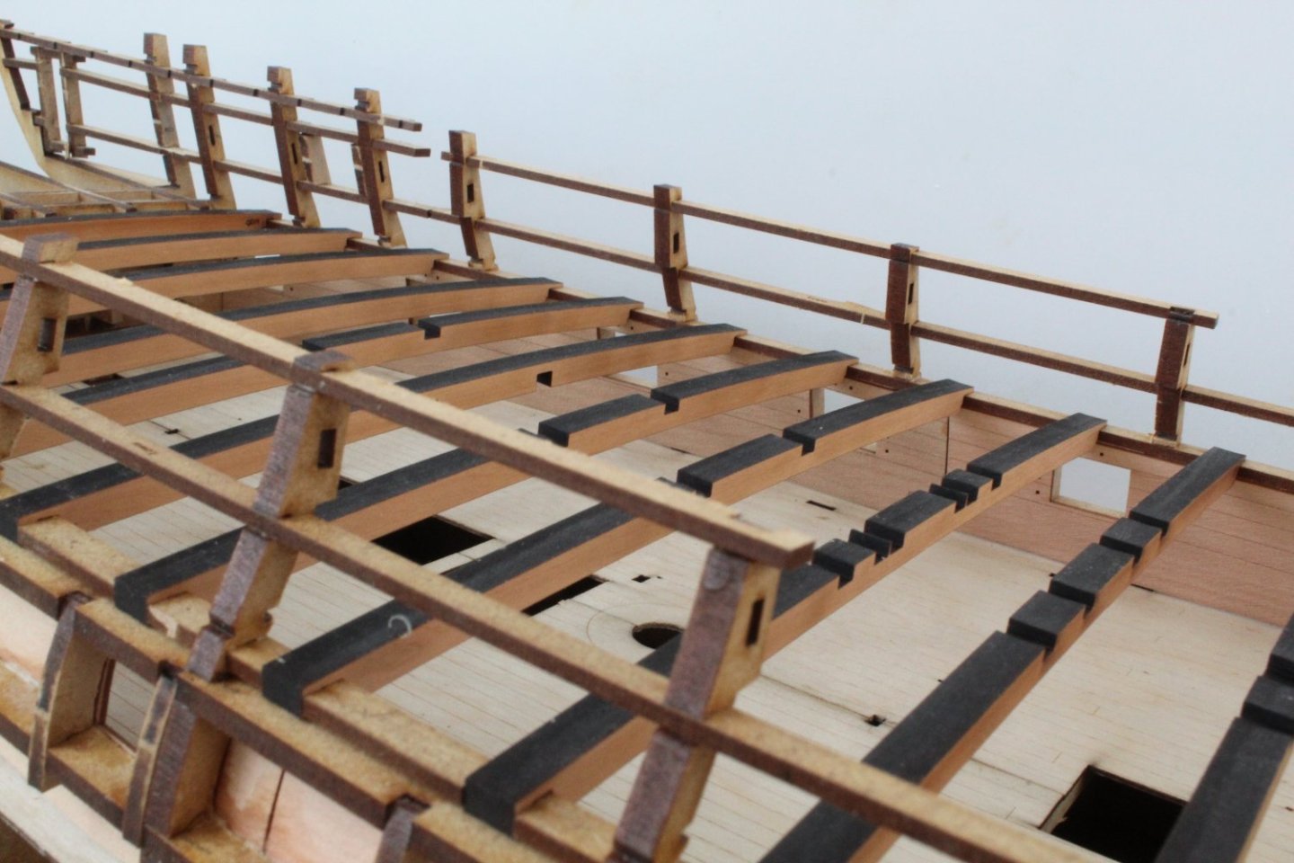
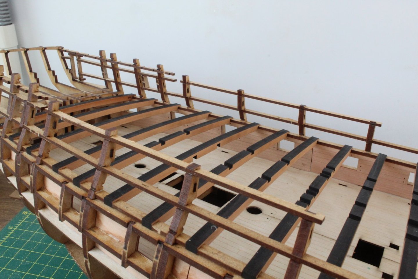
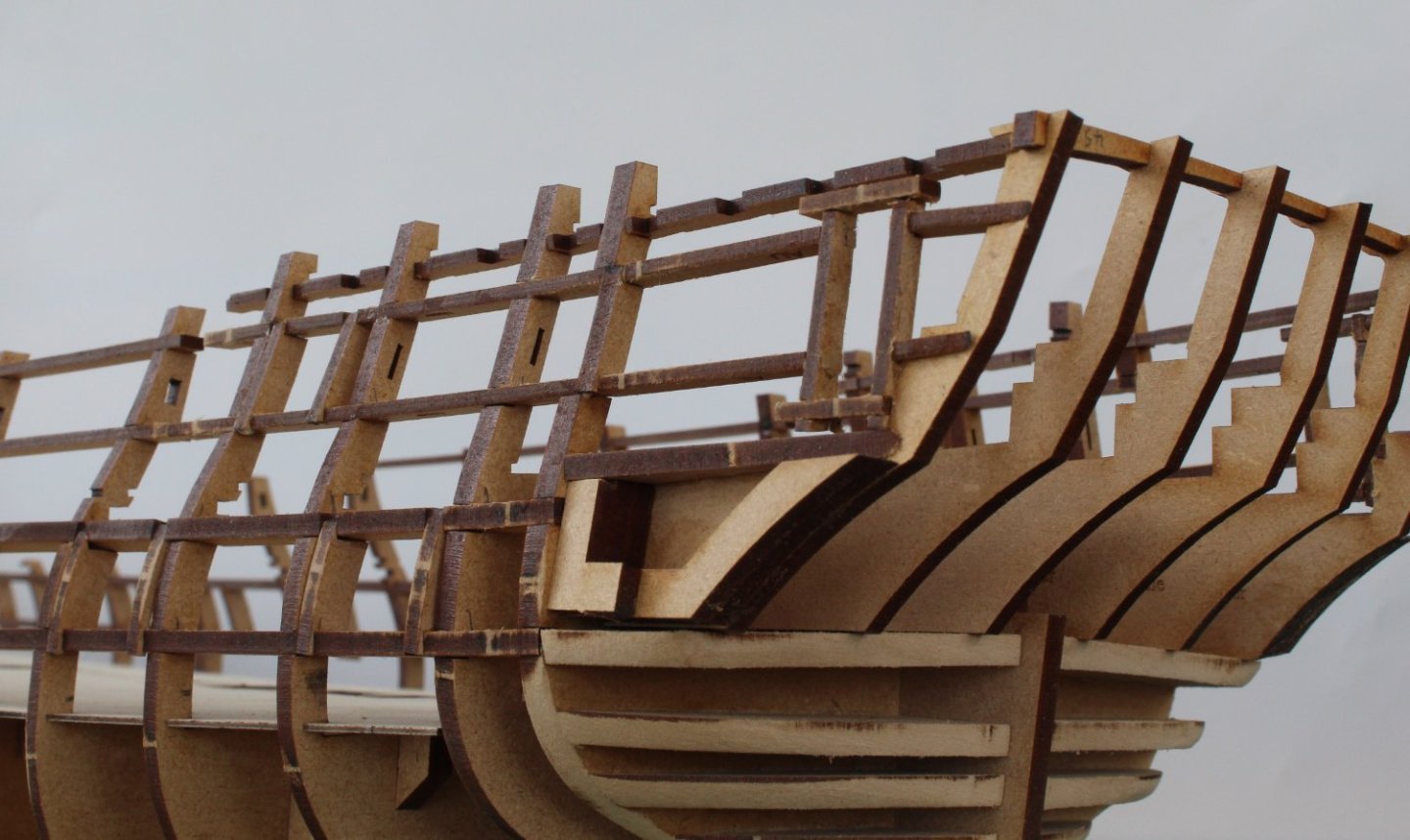
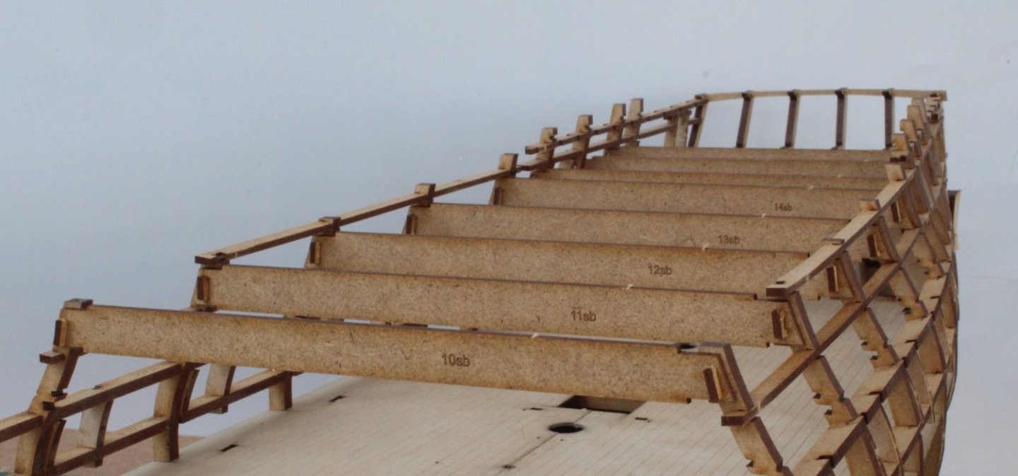
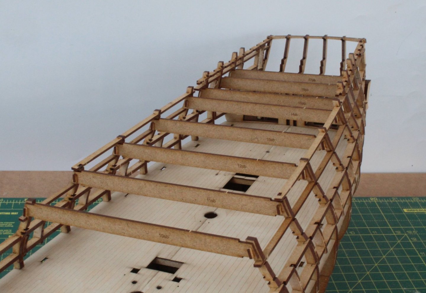
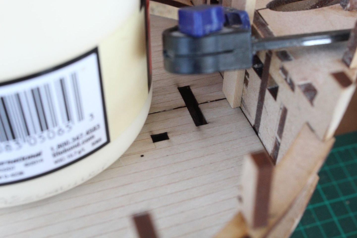
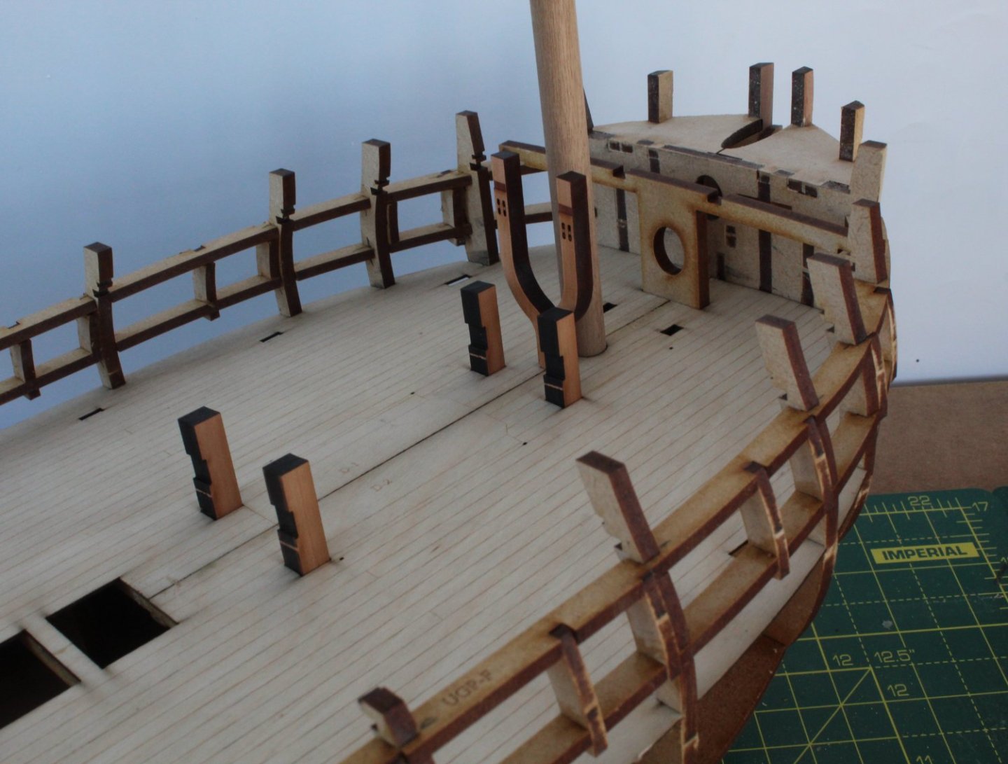
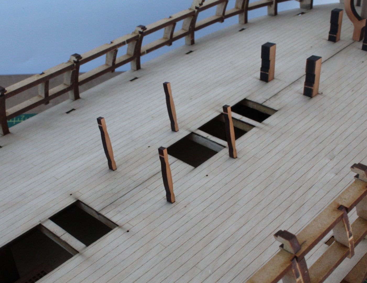
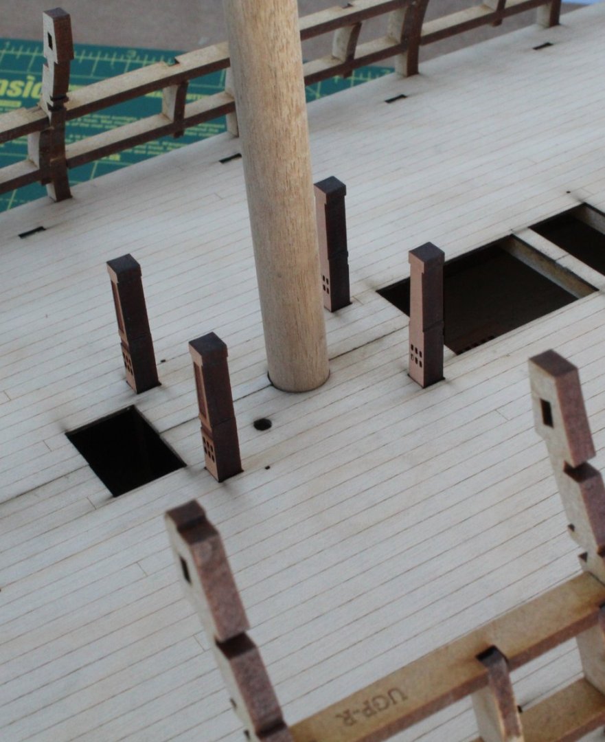
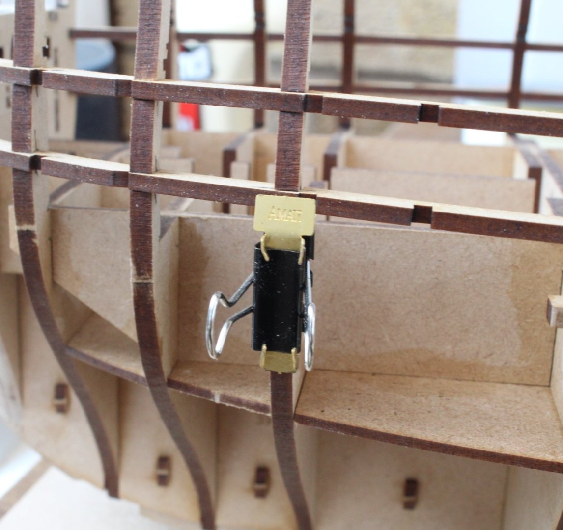
Inner Bulwark Patterns & Upper Deck Beam Ledges – Completed The various inner bulwark patterns were soaked in hot water for approx. 30 minutes and then clamped to the hull and allowed to dry for over 12 hours. The upper deck beam ledges were then dry fitted to make sure (once again) the bulwark patterns would locate without any fouling. Once I was happy with how everything was looking the ledges were removed and glue was applied to the framework. The various bulwark patterns were carefully positioned and clamped to the framework. I did also brush some diluted glue into the joints (from the outboard side) for good measure. Once the glue had been given time to cure the clamps were removed and the fore and aft upper deck beam ledges were refitted. The alignment of the ledge patterns was then checked by fitting the various deck beams. With the deck beams in place diluted glue was brushed into all the deck beam ledge / bulkhead joints. I was not totally happy with a couple of the bulwark pattern joints I clamped some wooden shims to readjust. The joints look much better The next few pictures show the upper deck beam ledges with deck beams in place, noting the deck beams are only dry fitted at this stage of the build. Next up will be fairing of the hull. I trip to B&Q will be required to acquire a new palm sander. I can’t decide between the corded or cordless black and decker palm sander.


- 587 replies
-
- 14
-
-
- Indefatigable
- Vanguard Models
- (and 1 more)
-
Sanding Inner Bulwark Frames – Completed With the hull on its side, protected with a folded towel, the sanding of the inner bulwark framework on the starboard side was completed. I took my time, with plenty of breaks, as I suffer with a bad back, following a lower disc prolapse several years ago which occurred when bending over to examine some engineering drawings. It didn't help my back either when I played lead guitar in a semi pro band for several years and eventually had to retire from gigging. For areas which required a lot of sanding I used 80-grit sandpaper initially and then used 120-grit. To finish off I used a 400-grit sanding stick. I found it tricky to sand, especially at the rear section but after a few hours of careful work the task was completed to my satisfaction. Before moving on to port side I decided a dry fit of all the bulwark patterns would be a good idea with the upper deck beam ledges (front and rear) in place. I did find it necessary to remove the laser char from the top and bottom edges of the bulwark patterns so they would fit under the deck beam ledge patterns. I started with fitting the bulwark aft pattern, and once I was happy with the gunport alignment the next pattern was added. All the gunport opening seem to be aligned with the bulwark patterns. After a few more hours work the port side bulwarks frames were also sanded smooth. After another dry fit with the deck beam ledges in place the port side bulwark patterns looked to be a good fit also. With the deck beam ledge patterns still in place I then tested fitted the forecastle, quarterdeck and poop deck beams. I was very pleased to note that all the deck beams fitted perfectly. The aft and bow bulwark patterns after being soaked in hot water for 30 mins were to clamped to the hull. I have done this so the patterns will take the shape of the hull’s lateral curvature. These parts will now be left overnight to dry out. I will then repeat the process for the two middle parts.


- 587 replies
-
- 20
-
-
- Indefatigable
- Vanguard Models
- (and 1 more)
-
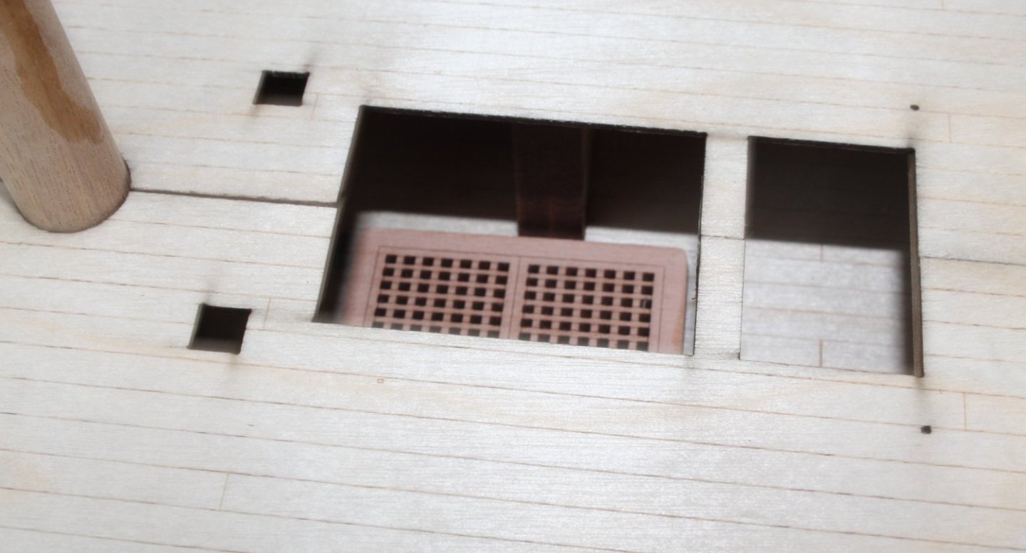
I need a new palm sander also. I have noticed that you have not removed the upper and lower gunport strips from the quarterdeck doorway. Is there any reason for this? The fairing looks good, so the planking should not be a problem for you.
- 443 replies
-
- 7
-
-
- Indefatigable
- Vanguard Models
- (and 1 more)
-
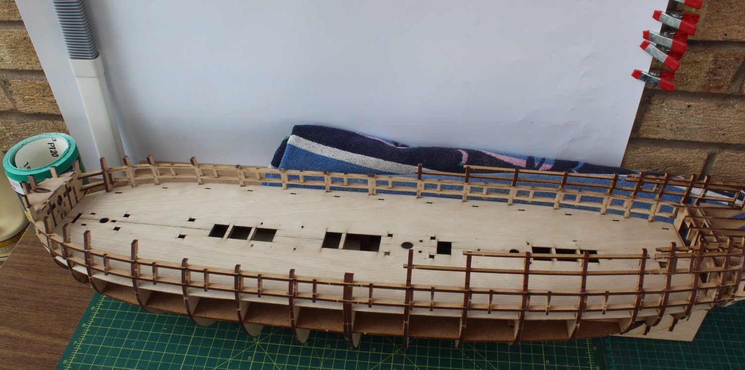
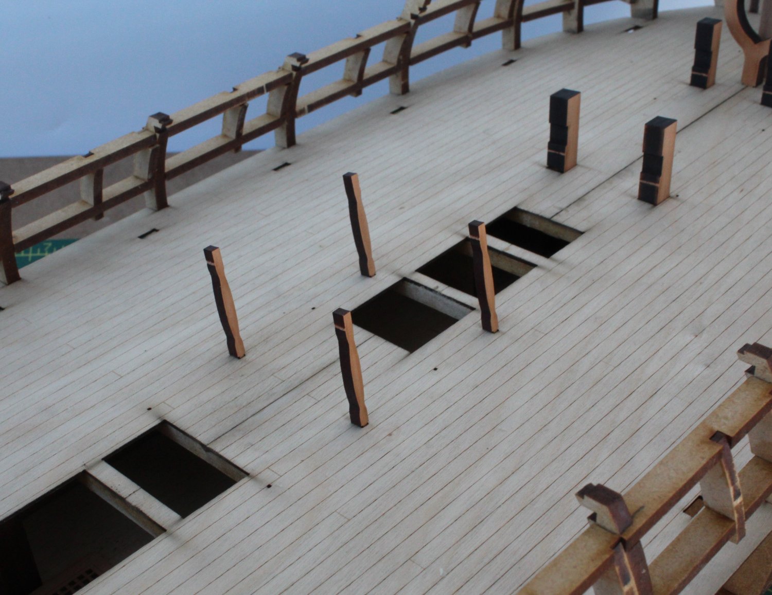
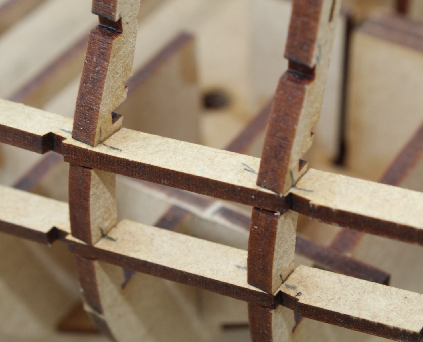
Sanding Inner Bulwark Frames I have started to sand the inner framework ready for the inner bulwark patterns. This needs to be done correctly so there is a good smooth contact surface for the patterns. This task will not be rushed and I know it is going to take me quite a bit of time and effort to complete. With reference to the first photo there are some areas that will require quite a bit of sanding to get a smooth transition between the bulkhead and gunport pattern. The first photo shows the work in progress where the first starboard bulwark pattern will be located. There is still a little bit more sanding required. As can be seen in the next photo there is still more sanding required on the bulkhead where the top longitudinal gunport pattern is connected. I am using a mixture of sanding sticks and sandpaper and my progress is slow but steady. I need to replenish my stock of sandpaper, so I heading off to my local DIY store. I am also checking the fit of the bulwark patterns, so far so good.


- 587 replies
-
- 12
-
-
- Indefatigable
- Vanguard Models
- (and 1 more)
-
Thanks Gary Dalby is very scenic, but I do enjoy the weekly parkruns, well not so much the run but the after run refreshments.These days my running is much slower so I can take in the vista as I gasp for gulps of air.
- 587 replies
-
- 2
-
-
- Indefatigable
- Vanguard Models
- (and 1 more)
-
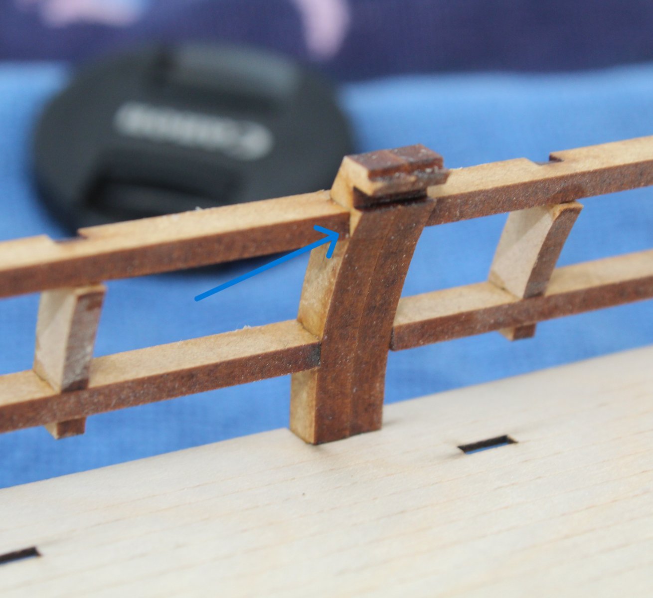
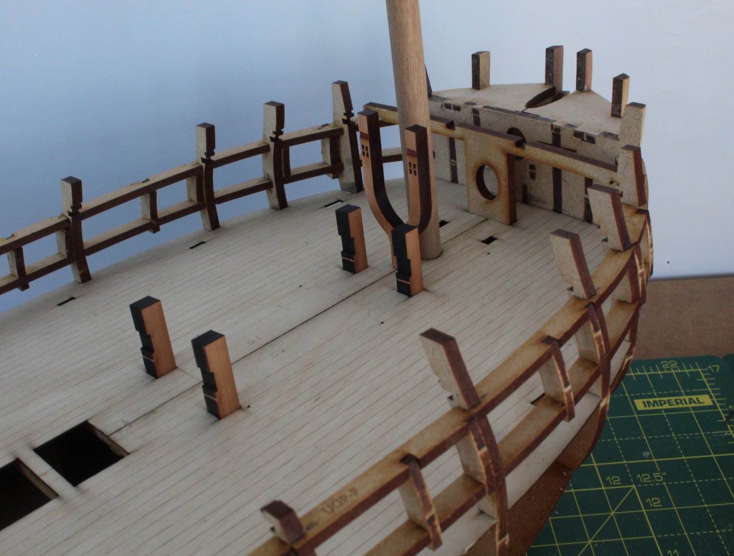
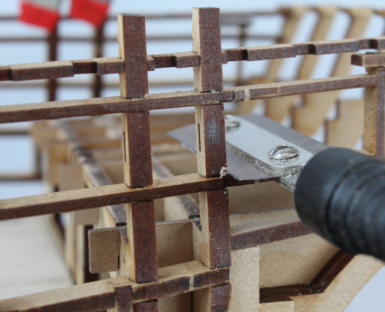
Not a good start to the day. My usual parkrun (Dalby Forest) had already been cancelled yesterday due to the icy conditions. Not to worry, having checked before setting off this morning, the North Yorkshire Water Park parkrun was still on. As I entered the car park I was informed, that due to the icy conditions, they had just decided to cancel for safety reasons. Rather than having my normal Saturday morning 5k parkrun and post run refreshments with some friends I was at a loose end. With a heavy heart I headed home. I eventually found solace in the shipyard. Fitting Aft Patterns There are several aft patterns to fit, which are identified as: Quarterdeck gun port strips (lower and upper) Quarterdeck bulwark strip (lower and upper) Quarterdeck door frame Poop deck beam ledge Quarterdeck gun port frames After a dry fit I used a cocktail stick to apply some titebond 3 to all the slots in the lower quarterdeck gun port and bulwark strips before they were added to the hull framework. This was followed with adding the upper quarterdeck gun port and bulwark strips. Once the glue had some time to grab and cure the quarterdeck door frame patterns were added. The two quarterdeck gun port sections, indicated by the blue arrow, which pass through the door frame will be removed once the glue has had time to dry. The poop deck beam ledge patterns were dry fitted. After making a few minor adjustments glue was added to the slots and the patterns added. The next photo shows the upper and lower quarterdeck bulwark strips in place. Before the quarterdeck gun port frames can be fitted it is necessary to remove a small section of bulkhead 18. I used a small razor saw to make the cuts. Once the small section has been removed the edges were sanded smooth with a small needle file. As indicated earlier in this post the quarterdeck gun port strips that pass through the quarterdeck door way also needs to be removed. This was easily done with a small razer saw and then I used a file to smooth the cut edges. Next the quarterdeck gun port frames were added, as indicated by the blue arrow. Before starting to sand the inner bulwark frames so they are smooth and ready for the inner bulwark patterns to be added I did a test fit of the temporary beams for bulkheads 15 to 18 which, when in place, will create a rigid structure for fairing. I know I will have to be careful with protecting the bulkhead ears during the sanding process therefore I will follow the excellent advise given in Jim’s prototype build log: “you're best rolling the hull onto its side on a towel, and applying pressure downwards when sanding. This is done until everything is nice and even.”


- 587 replies
-
- 15
-
-
- Indefatigable
- Vanguard Models
- (and 1 more)
-
I'm really looking forward to seeing plenty of photos of the sanded hull. I trust all goes well with the hull fairing.
- 443 replies
-
- 4
-
-
- Indefatigable
- Vanguard Models
- (and 1 more)
-
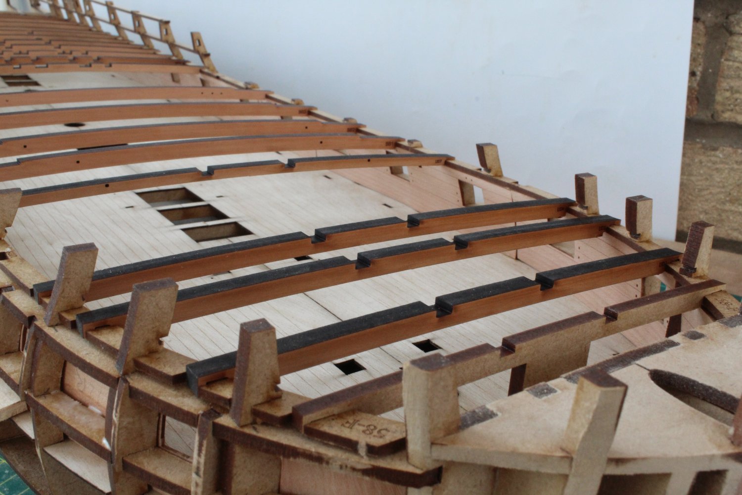
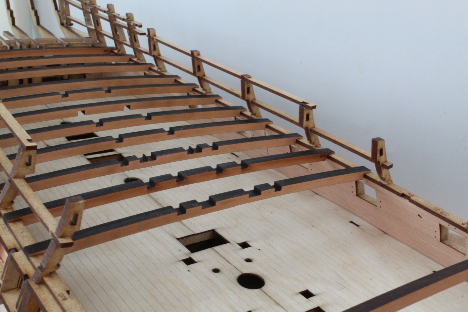
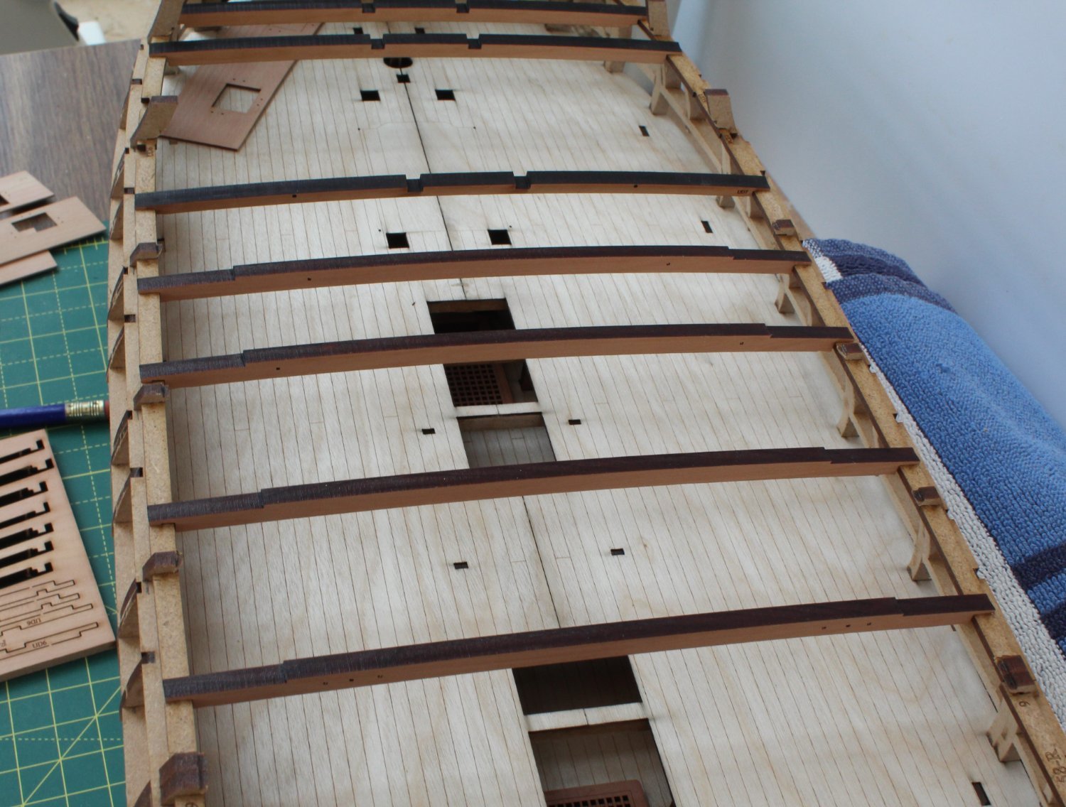
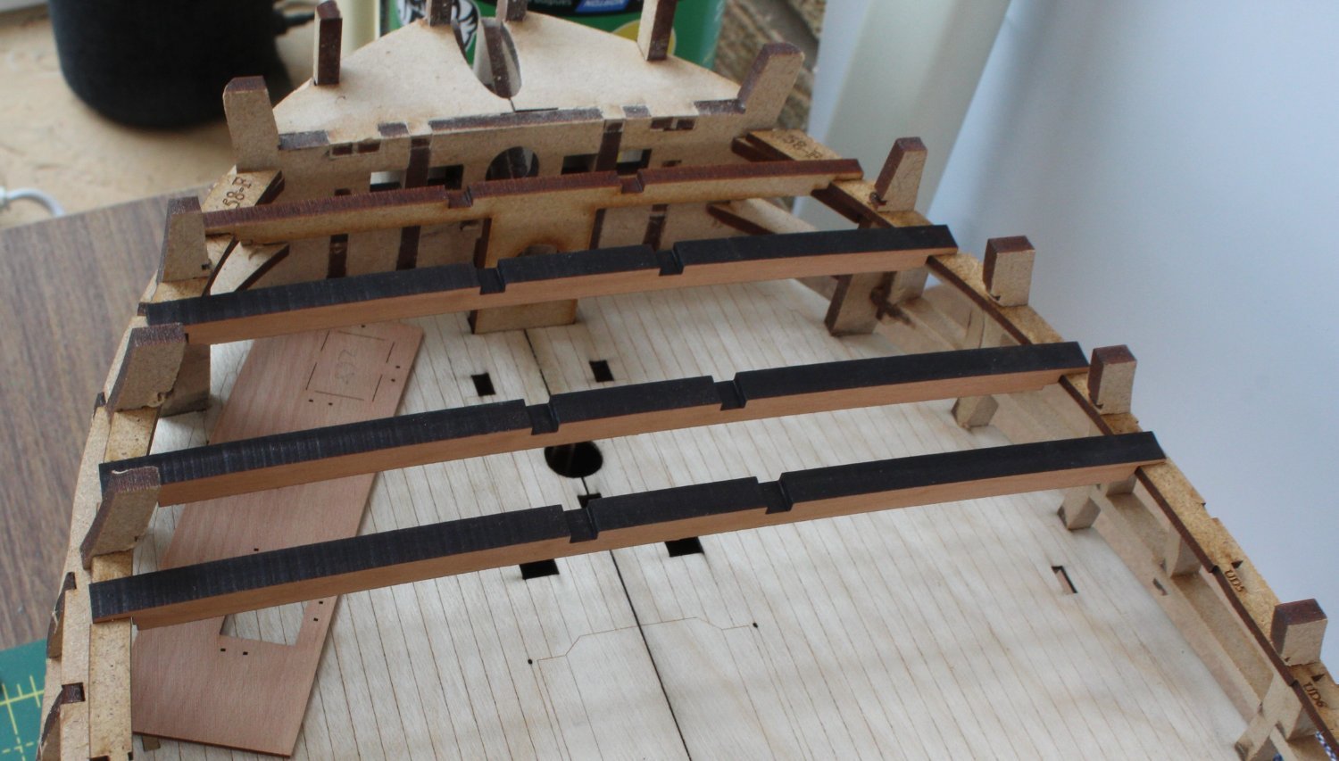
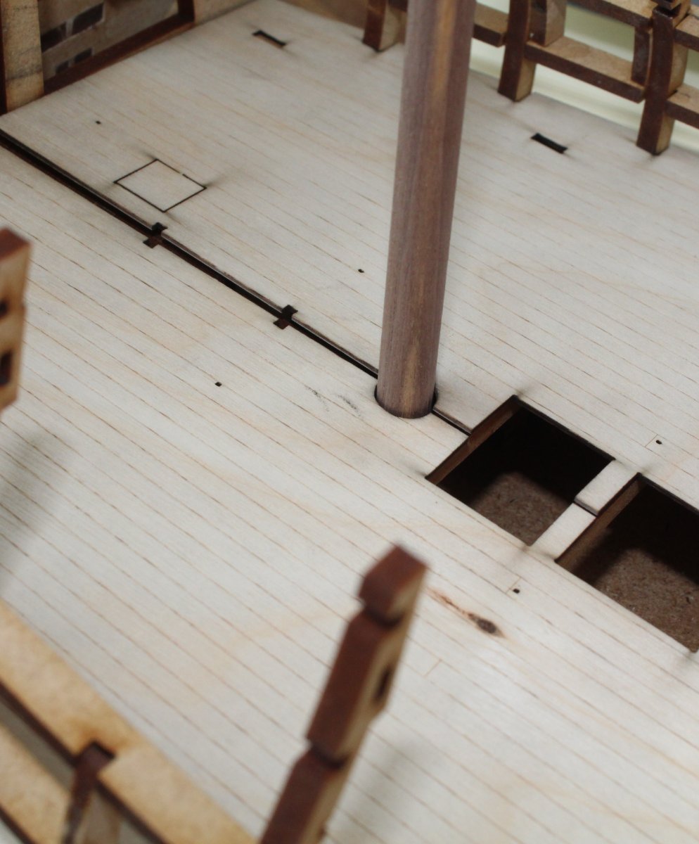
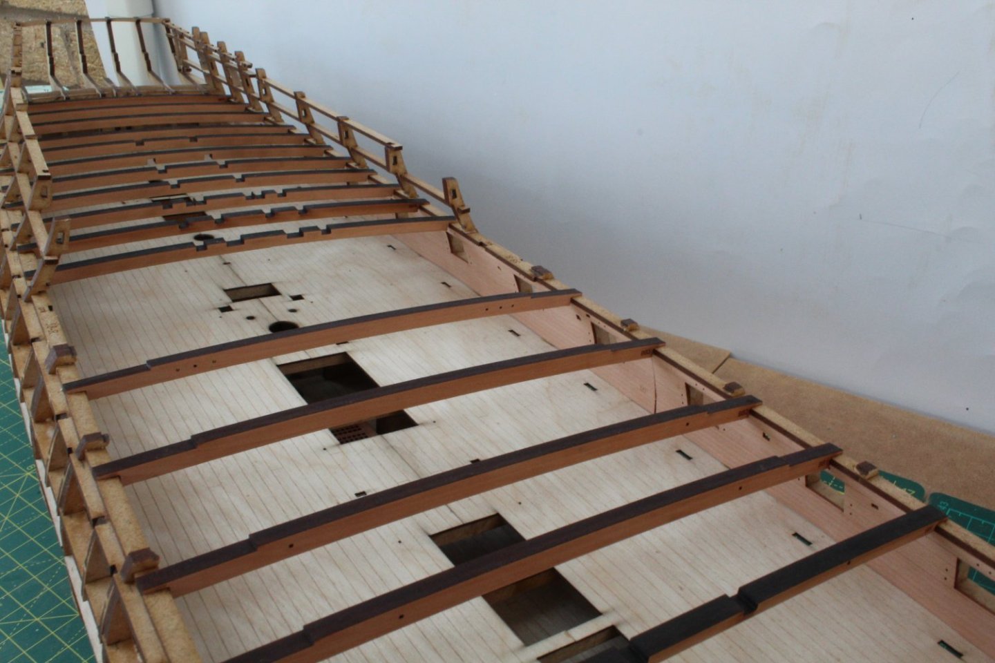
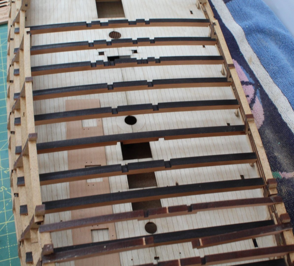
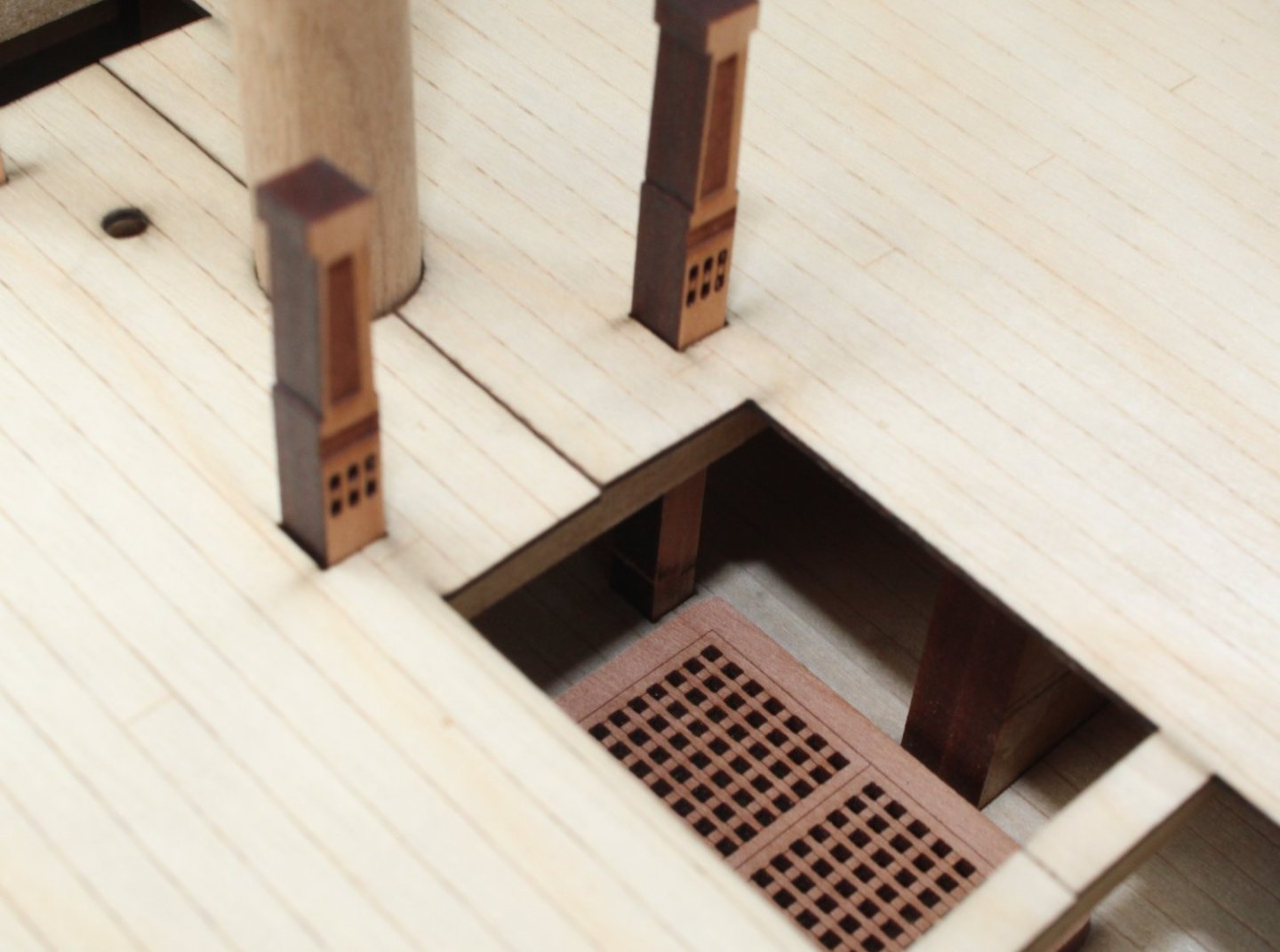
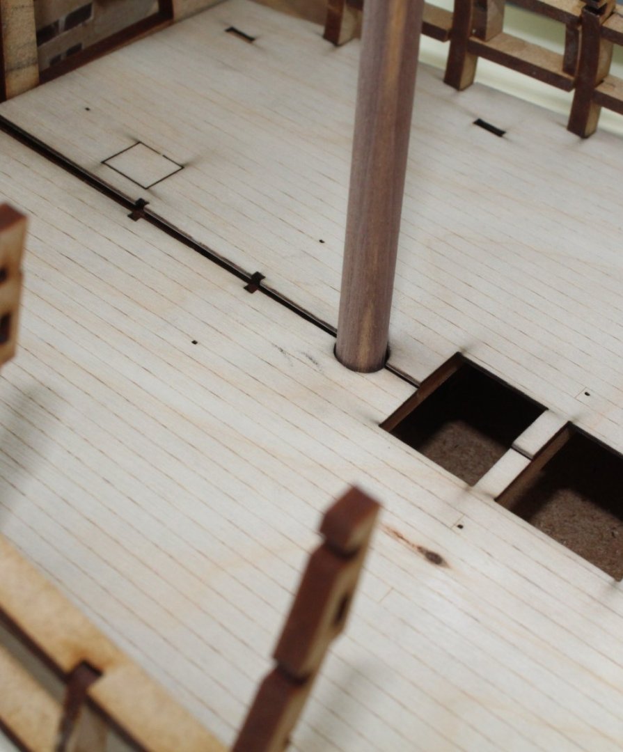
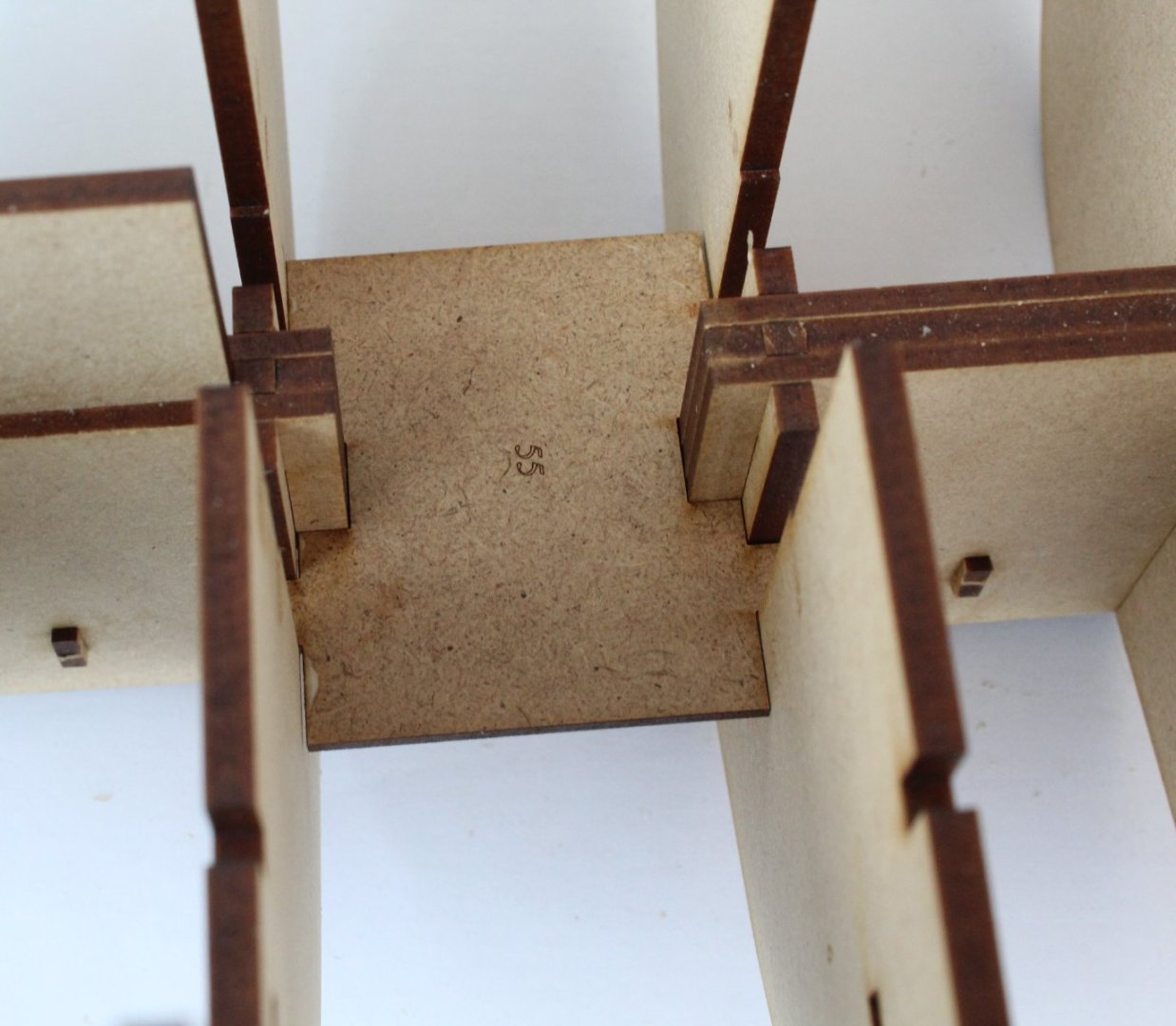
This post will detail the work I undertook to install the gundeck plywood patterns and stern counter frame patterns. There a a lot of photos to look at. Gun Deck Plywood Pattern – Installation After another dry run I went ahead and glued the plywood gundeck patterns in place. Once the gundeck was in place I could feel there was full contact between the gundeck beams and the deck along the outer edges. A series of clamps were used to hold the central section in place as the glue cures. Although not shown in the photo below I did also place some weighted objects on the deck. As can be seen in the next photo the cut-outs between the two gundeck pattern are nicely aligned. The only area where the deck did not seem to sit flat was at the bow end. I tried a heavy weight and then a simple clamping arrangement as shown below. I was not totally happy that the decks were totally flat so ended up using a modified version, as shown below, which was successful. Once the glue had cured it was time, once again, to test fit some of the deck items, particularly those items which locate in slots on the lower deck. Fitting Stern Counter Frame Patterns There are 3 stern counter frame patterns per side, inner, middle and outer. Before fitting I removed the laser char from the stern frame pattern slots which locate over bulkheads 18 and 17. Once the laser char had been removed each pattern was fitted with out any problem. Next the stern frame connecting beam was added. Before the stern frame filler pattern (deck level) can be fitted the top edge requires bevelling. It is not a great photo of the bevel edge. After bevelling the stern frame filler pattern (deck level) it was glued in place. I used a couple of clamps to hold the pattern in place. Three additional stern filler patterns were then added. To finish off today’s work I dry fitted the aft quarter strips and door frame patterns. These were all a good fit.


- 587 replies
-
- 17
-
-
- Indefatigable
- Vanguard Models
- (and 1 more)
-
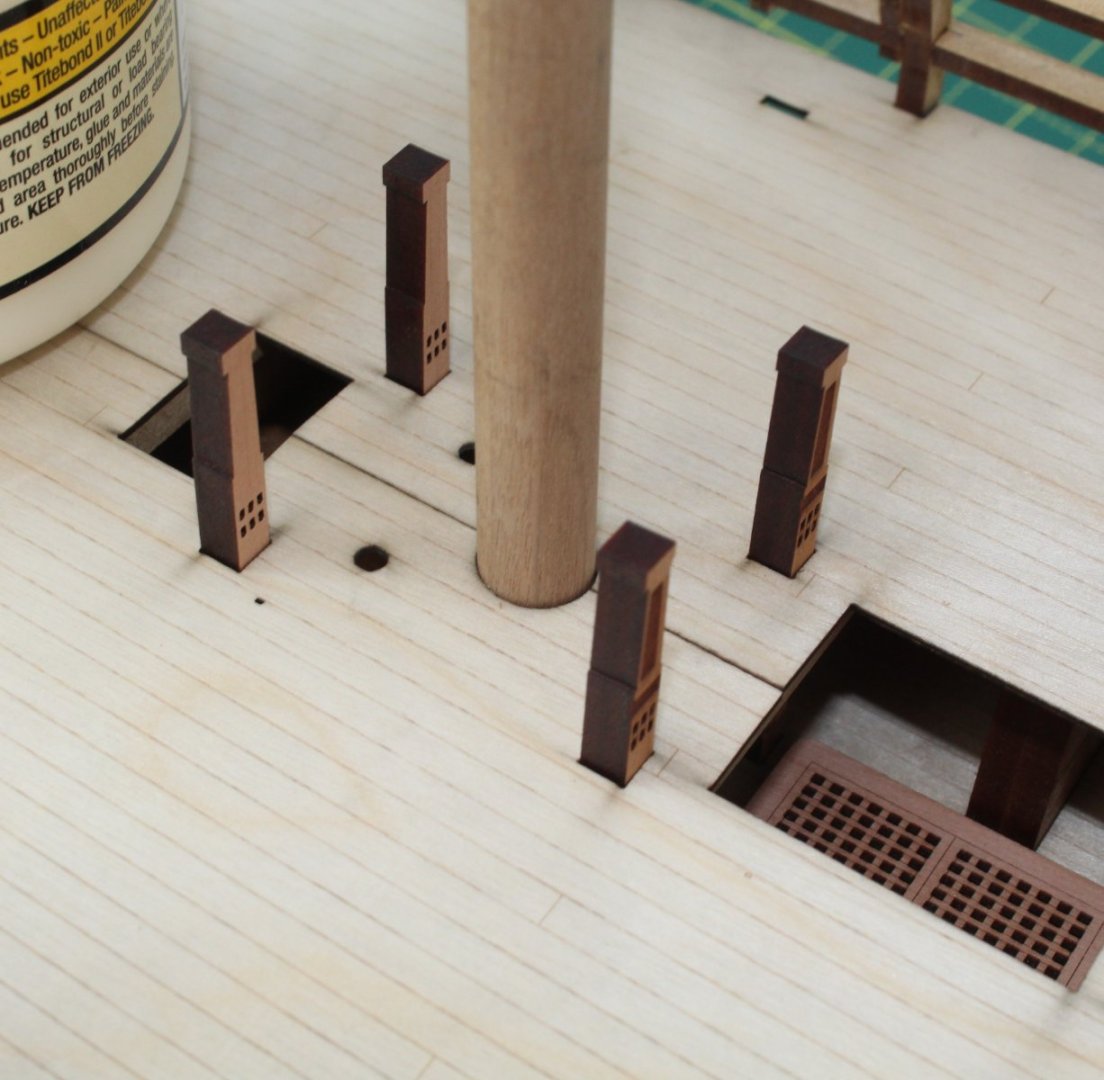
Gun Deck Plywood Pattern – Preparation Work With our youngest grandson having his afternoon nap I was able to grab 90 minutes in the shipyard. I decided to have a look at fitting the gundeck. The plywood gundeck base comprises 2 plywood patterns, a left-hand and a right-hand side. To ensure the two patterns are correctly aligned the manual does detail taping the two sections together before installation which will act as a hinge to aid the installation. The build manual also recommends doing a couple of dry runs before the gundeck is glued to the gun beams. It is important to make sure the deck assembly slots fully into the bulkhead notches thus holding the outer edges of the gun deck in place. For my first dry run I tried to fit the left-hand side pattern. I was unable to get the pattern to engage with some of the notches, between bulkheads 5 to 15. After a close visual inspection of each bulkhead notch with a high intensity light I could see no apparent reason for this. I then used a piece of scrap material taken from the gundeck’s plywood sheet and checked it would locate in the bulkhead notches. No problems were detected. Being a little perplexed I decided to see if I could fit the right-hand gundeck pattern. With the Indy turned around on my workbench I was able to fit the right-hand side pattern without any problems. With the right-hand deck still in place I tried once again to fit the left-hand pattern and eventually it slotted into place. With a slight bit of adjustment of the gundeck patterns, the central gundeck cut-outs were almost aligned. With both gundeck patterns removed, using a 400-grit sanding stick, I removed the laser char from the sides of the bulkhead alignment slots on both patterns. The gundeck patterns were then refitted, the cut-outs were nicely aligned. With some heavy object to hold the deck sections in place I did a test fit of some of the deck items to ensure would pass though and locate in the slots provided on the lower deck. I am pleased to report the various bitts and mast dowels were perfectly aligned with the lower deck. With the two gundeck sections removed tape was applied to the underside and then refitted. Everything is now looking good. I might be able to get a little bit of time in the shipyard in the morning before more babysitting duties with a couple of our grandsons. I am planning one more gundeck test fit and then, assuming there are no problems, the gundeck patterns can then be glued in place. My progress is slow but I happy taking my time and double / triple check things before committing to gluing.
- 587 replies
-
- 12
-
-
- Indefatigable
- Vanguard Models
- (and 1 more)
-
Gun Port Patterns – Installation Following on from my last post where I detailed the preparation work with regards to the upper and lower gun port longitudinal frame patterns I have now glued patterns in place. I brushed glue in both the pattern and bulkhead slots. After each pattern had been glued in place a wetted paint brush was used to remove the excess glue, with some of the excess diluted glue being brushed into the joints. The pencil lines do match up so I know the patterns are fully engaged in the bulkhead slots. The patterns, when glued, stayed in place without the need to use clamps for the most part. There were a couple of bulkheads where it was necessary to hold them in place. Before removing the vertical gun port patterns from the MDF sheet, I did add a part reference in pencil. I then dry fitted all these vertical gun port patterns all to make sure there was no installation issues. Next each vertical gun port pattern was removed in turn and the pencil marks were removed with an eraser. Glue was added to both the pattern and bulkhead slots and the pattern was then refitted. The excess glue brushed away with a wetted paint brush, with some of the excess diluted glue being brushed into the joints. It did not take too long to glue all the patterns in place. Next task should be the fitting of the gun deck sections and stern counter frame patterns. I will have limited time in the shipyard over the next few days due to grandparent duties so not sure when this will be done.


- 587 replies
-
- 19
-
-
- Indefatigable
- Vanguard Models
- (and 1 more)
-
It makes more work with the planking, otherwise you will need to modify the cannons to remove the locating tab. Have fun deciding. Your planking does look good.
- 443 replies
-
- 5
-
-
- Indefatigable
- Vanguard Models
- (and 1 more)
-
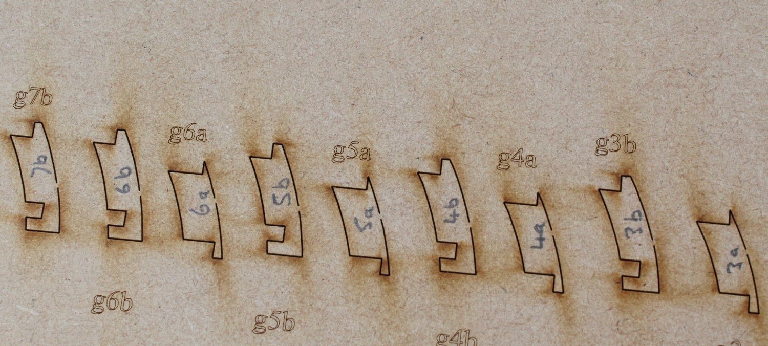
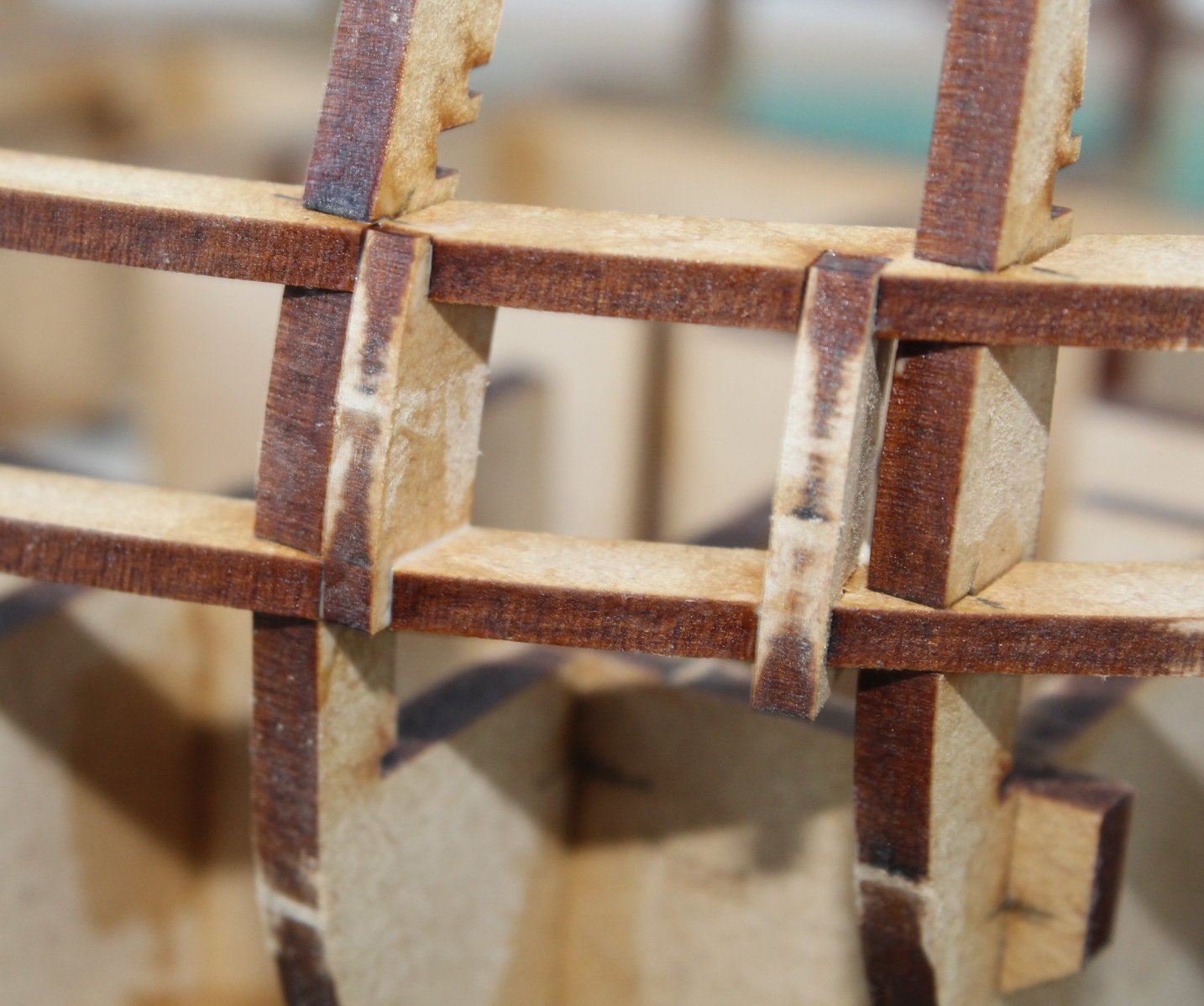
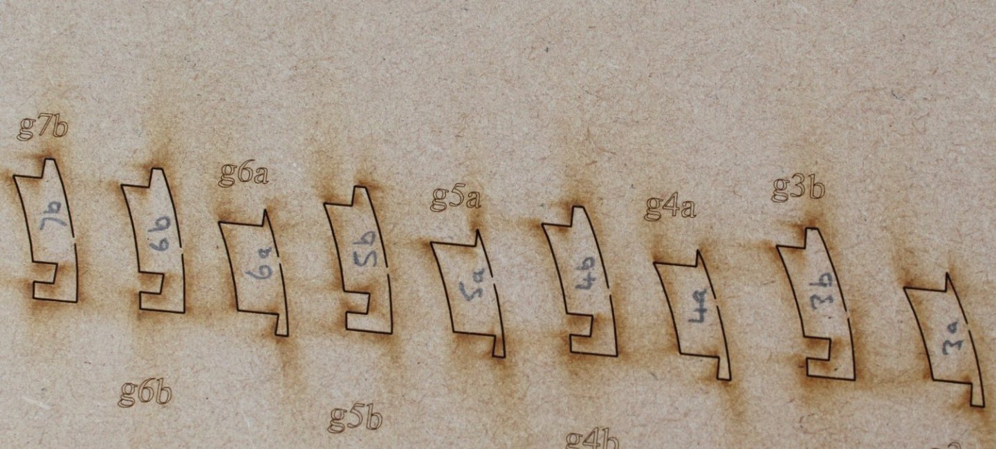
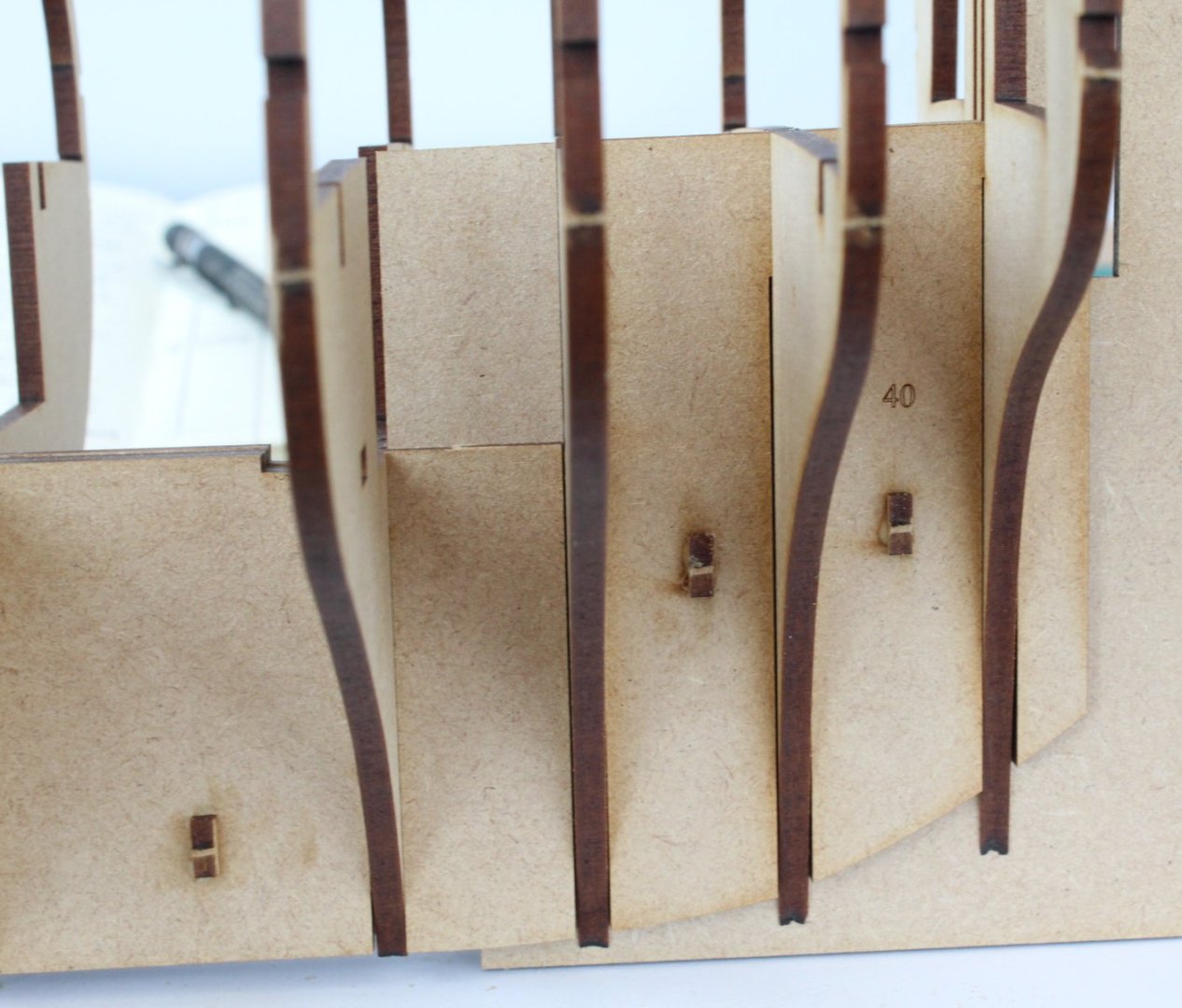
Gun Port Patterns – Preparation Work There are 4 off gun port longitudinal frame patterns per side to fit, 2 for the lower framework (front and rear) and 2 for the upper framework (front and rear). Care must be taken with handling these patterns as they are fragile. I did very gently remove some laser char from the frame pattern bulkhead slots on these patterns using a 600-grit sanding stick. I have dry fitted the front lower and upper patterns to the right-hand side. Some of the excess material will be removed when sanding the inner framework smooth for the bulwark patterns and when fairing the hull ready for the first planking. I have already noted (as shown in the build manual picture with build step 144 for example) that some bulkhead material around the gun port 1 was not removed during the fairing process with the prototype build. The big guns from the IJN Yamato are slowing turning towards the Indy. The forward edge of the fore bulwark patterns terminates next to the rear edge of bulkhead 2, as shown by the blue arrow. There is a small bulwark pattern option which can be fitted between bulkheads 1 and 2. I have now added some pencil marks on all the bulkheads and patterns joints. These marks will match when the gun port longitudinal frame patterns are fully engaged in their respective bulkhead slots. It is a belt and braces approach but, given the some of the edges are not flush when the patterns are fitted, I know the patterns will be correctly installed when they are glued in place. The next picture shows the Indy with all the gun port longitudinal frame patterns dry fitted. Before gluing the longitudinal frame patterns to the bulkheads, I decided to dry fit a random selection of the main deck gun port vertical frame patterns. I am using pencil marks to ensure the patterns are fully engaged. The dry fit check has already paid dividends as in the photo below the first vertical frame pattern is upside down. Thankfully, with my enhanced checking procedures, I soon realised my mistake. With the vertical gun port frame fitted the right way up it can be seen that the pencil marks match up indicating the pattern is fully engaged.


- 587 replies
-
- 16
-
-

-
- Indefatigable
- Vanguard Models
- (and 1 more)
-
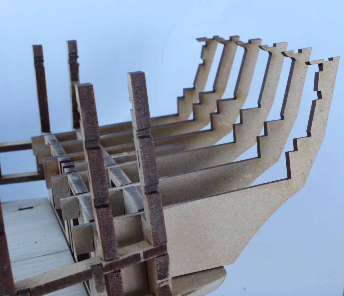
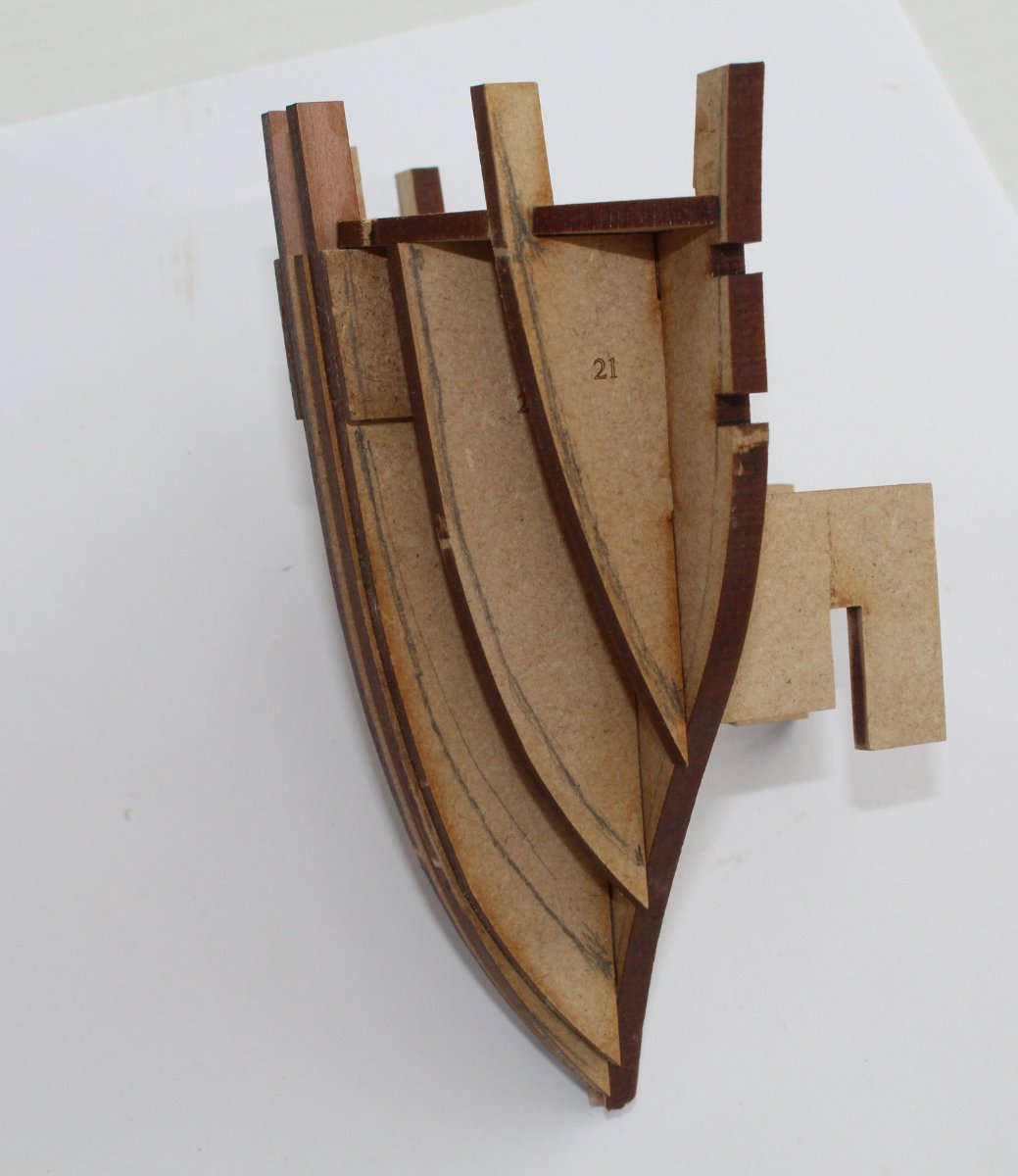
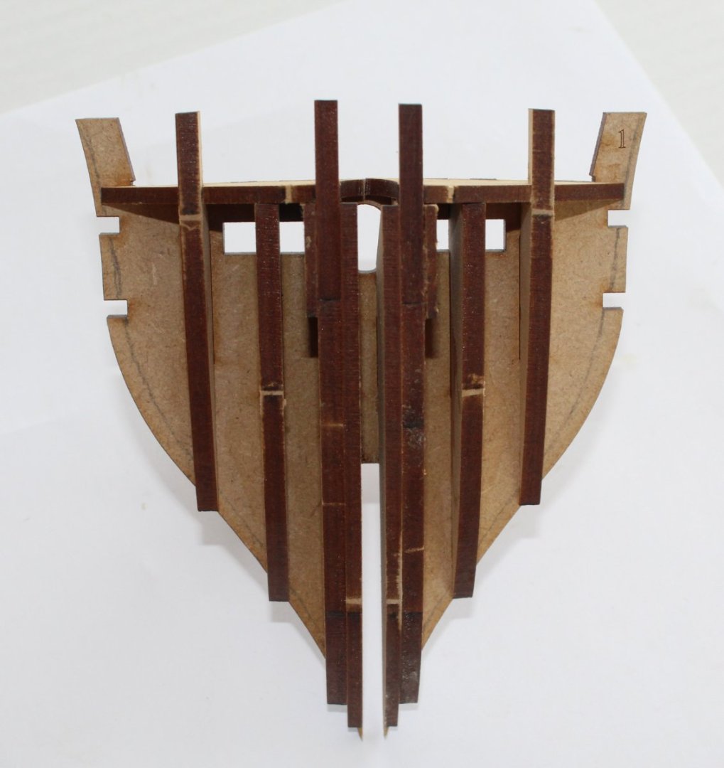
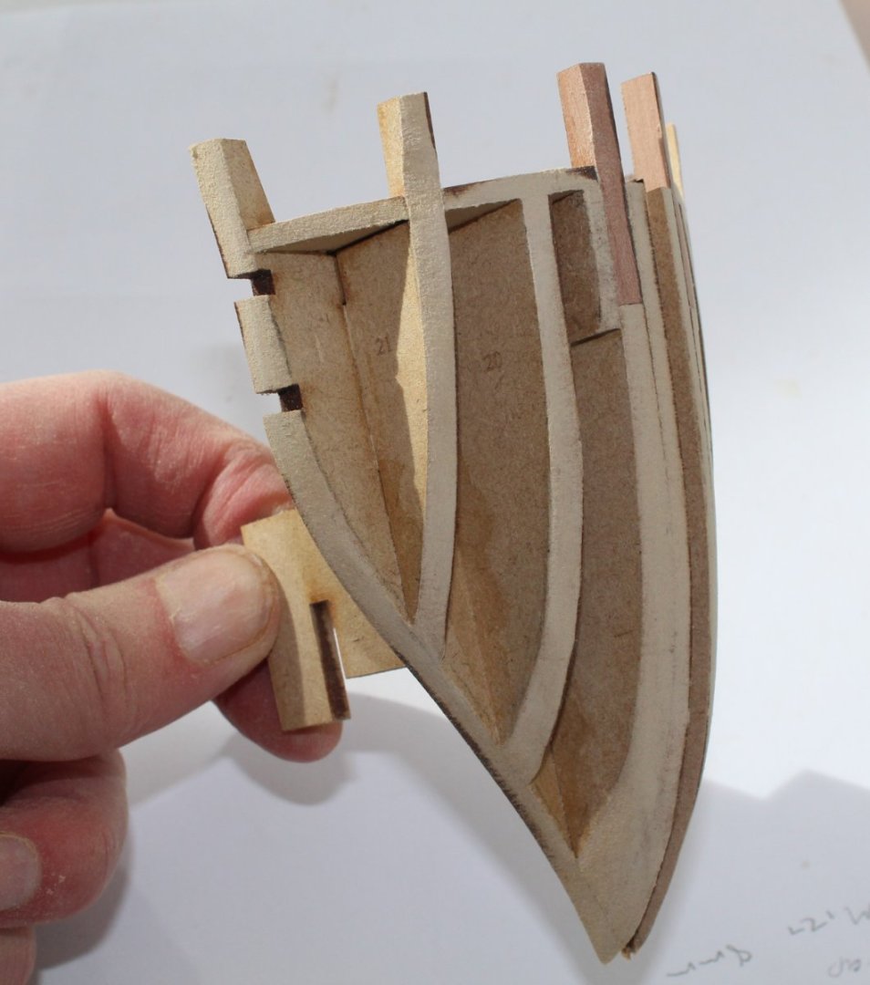
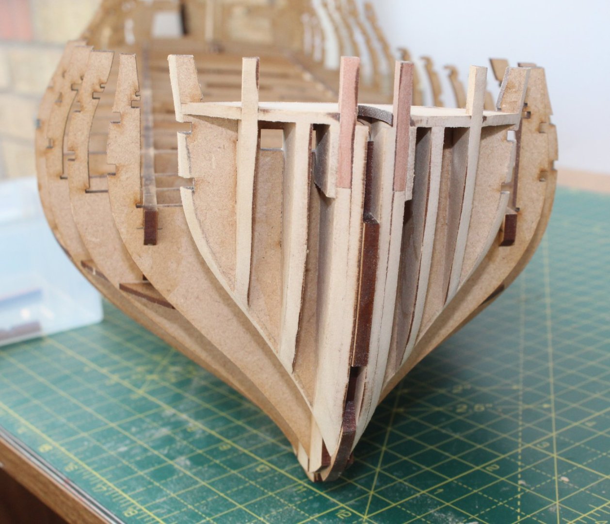
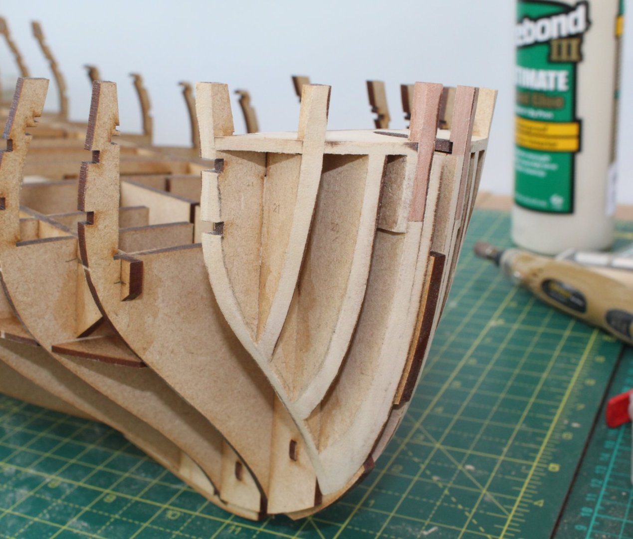
Fitting Bulkhead 1 The various bow filler parts were dry fitted to the bulkhead and a test hull fit was undertaken. Next some guidelines were drawn on the bulkhead in readiness for the pre-fairing, as can seen in the first photo below, using the photo in the build manual as a reference. Fairing guidelines were also drawn on the filler patterns. Using a combination of a Ginour rotary tool, sanding sticks and sanding blocks the pre-fairing of the bulkhead was completed. The completed bulkhead assembly was then added to the keel. Fitting Bulkhead 18 The various stern filler parts were dry fitted to bulkhead and I started to add some guidelines. After the filler patterns had been glued in place the pre-fairing of the bulkhead assembly was completed. I generally find the pre-fair of this type of bulkhead assembly much tricker than the bow assembly. I took my time and stopped to check the progress at regular intervals, and also compared with the photos in the build manual. The final task was to take the 2 off stern patterns, shape and fit. There is quite of bit of sanding required to shape these patterns, I have left of bit of excess material on these patterns which can be removed during the final hull fairing later in the build process. The pattern has not, as yet, been glued to the keel in the photo below.


- 587 replies
-
- 15
-
-
- Indefatigable
- Vanguard Models
- (and 1 more)
-
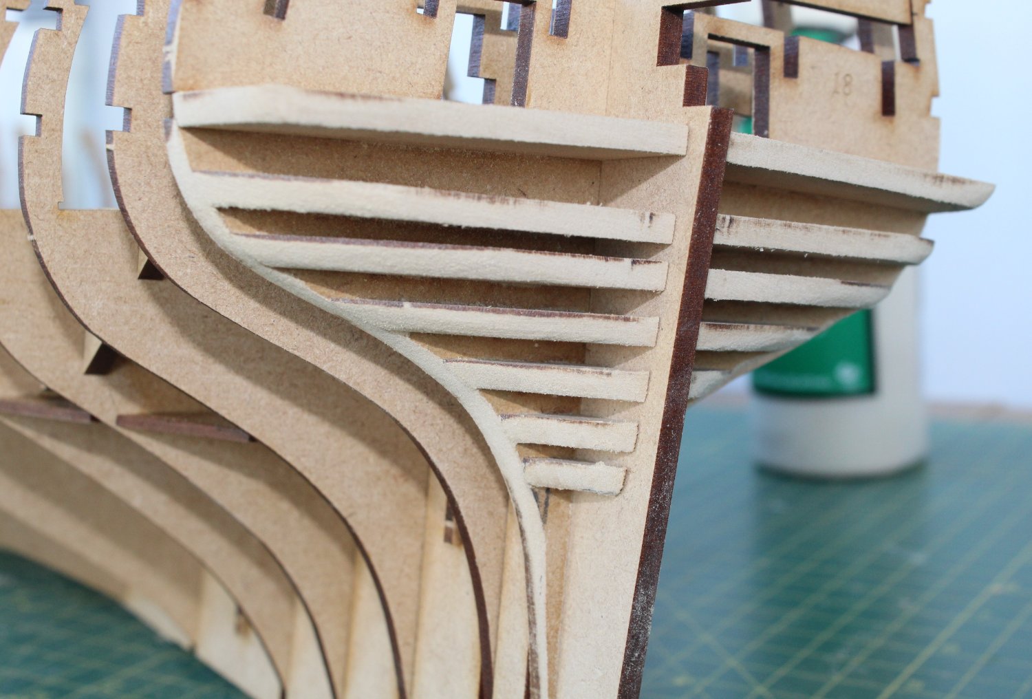
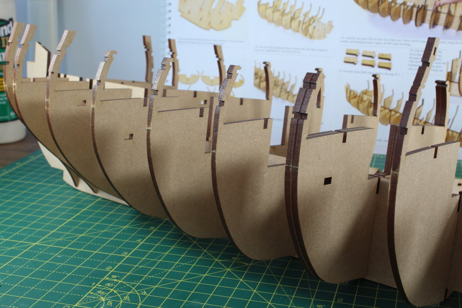
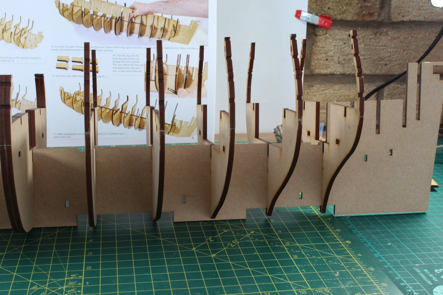
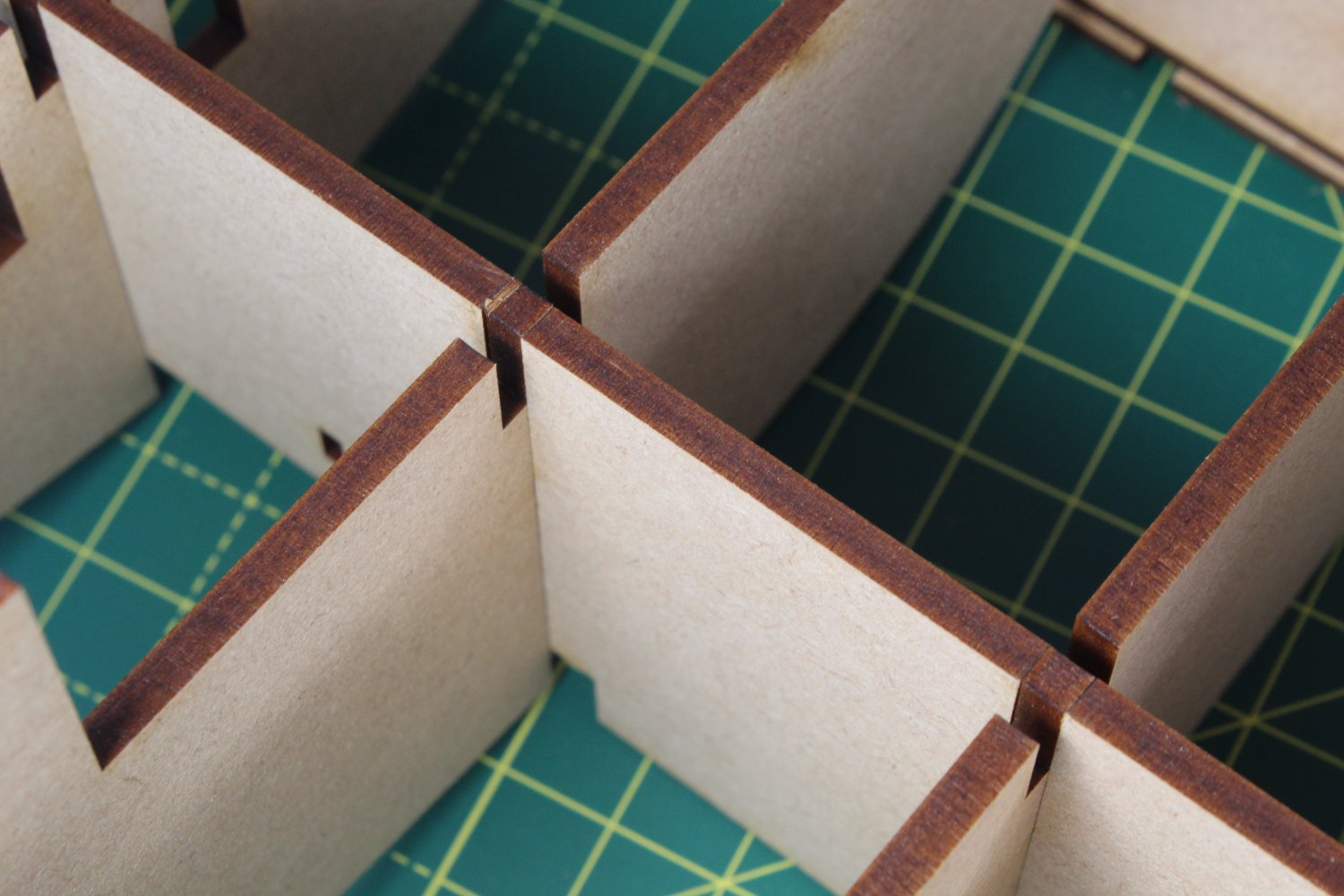
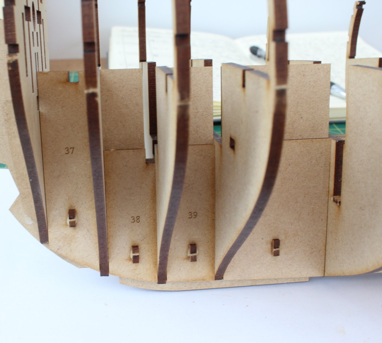
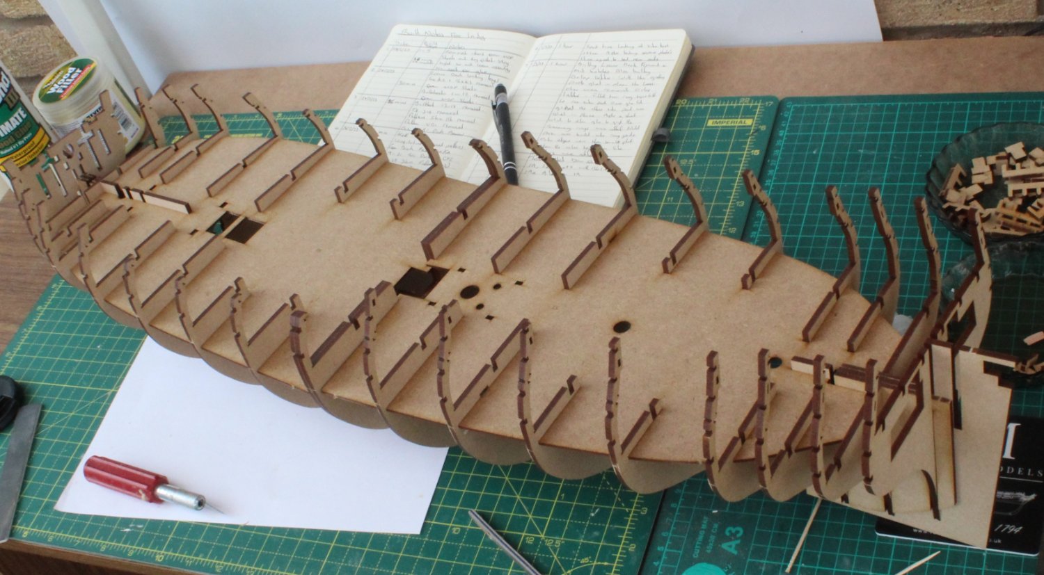
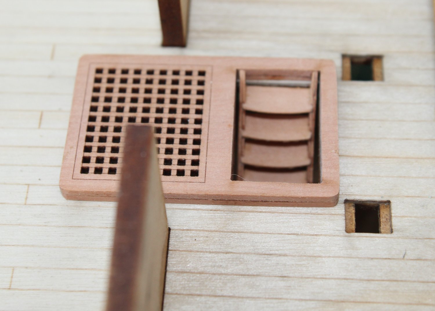
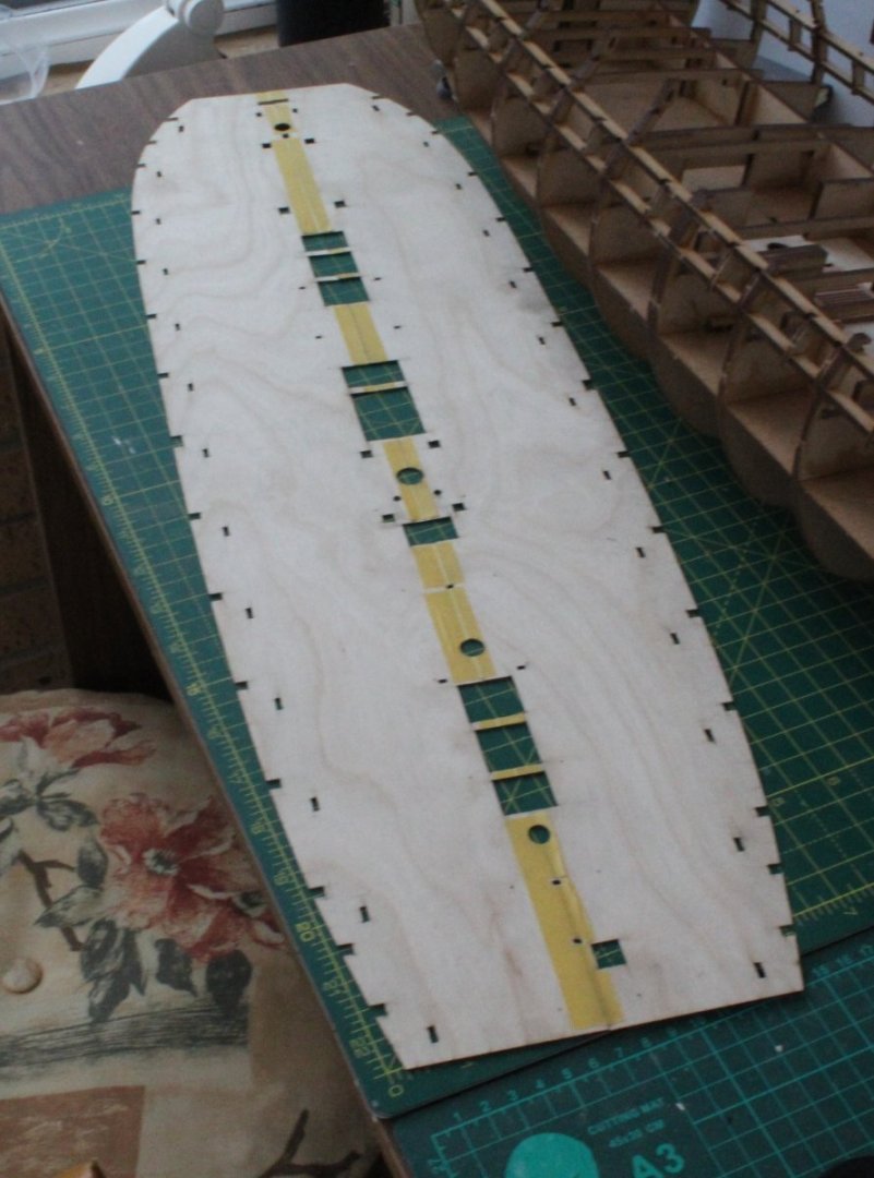
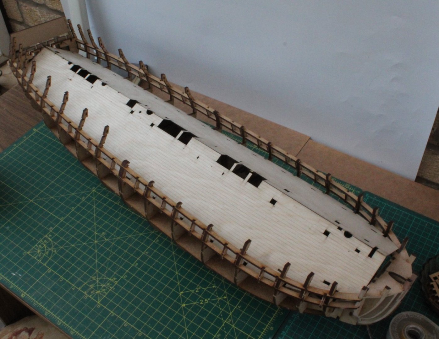
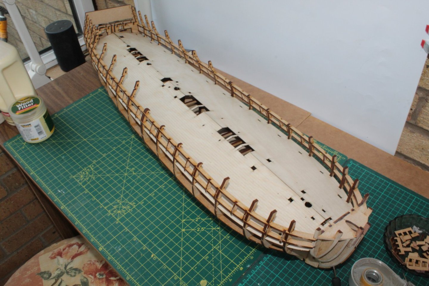
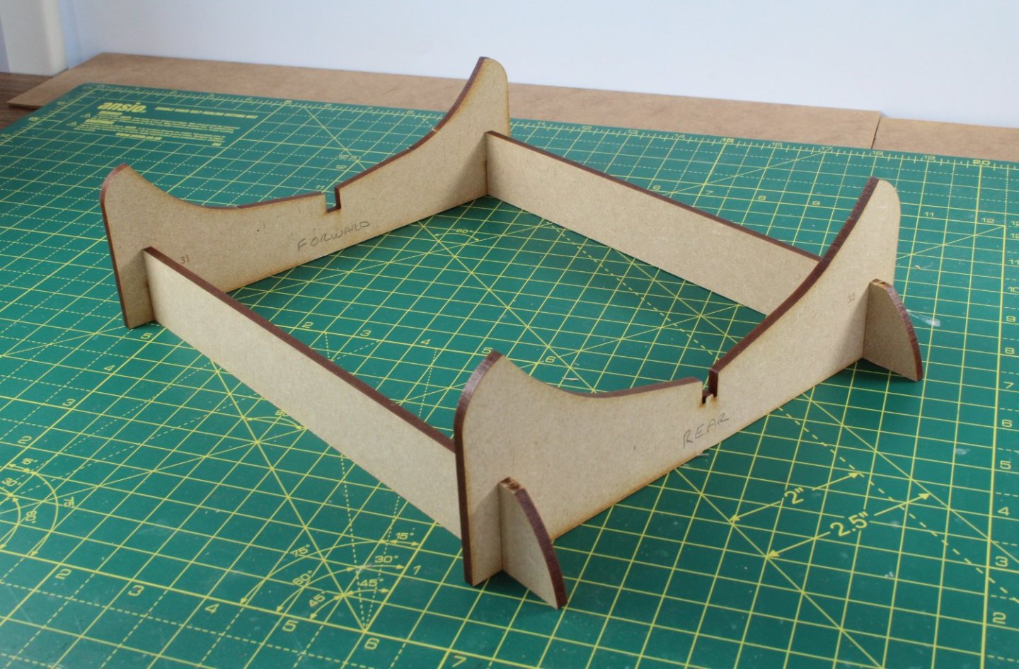
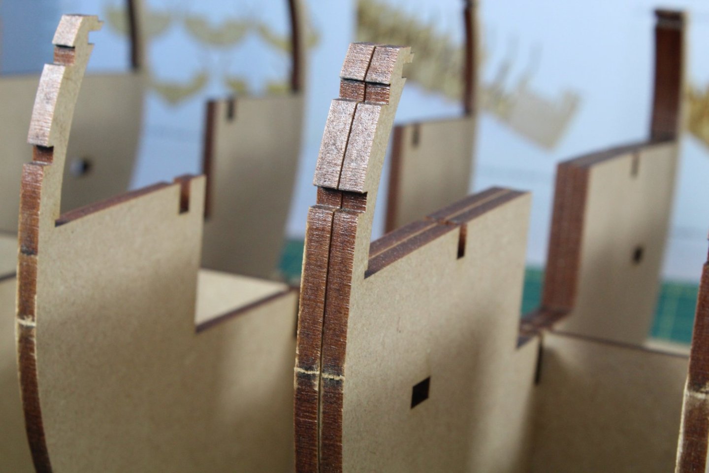
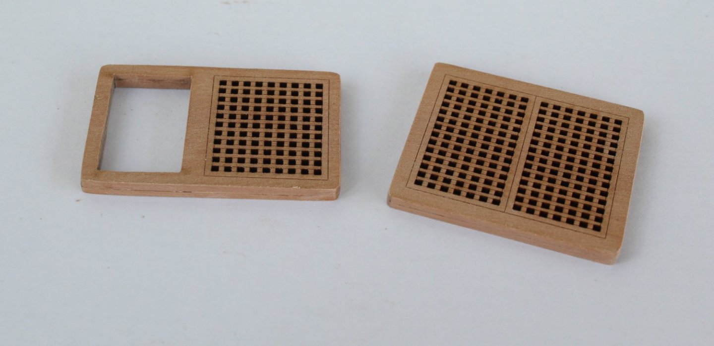
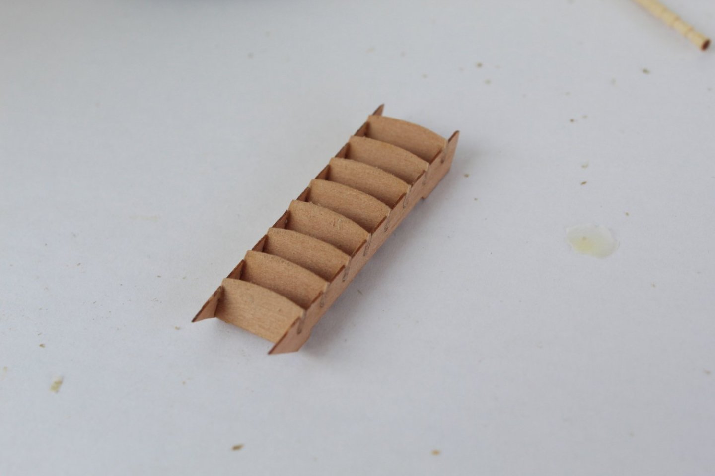
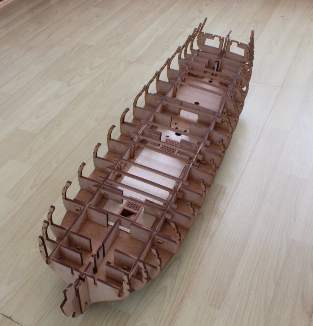
When I started my last Indy build log I realised that I should have included some earlier build photos. Rather than post them out of sequence (OCD or what) I decided to delete and start again, sorry for the confusion. You will also note I have changed my user name to Glenn–UK. Please find attached my first set of photos which represents what I achieved during week 1 of the build process. Photo 1 - The temporary build cradle Photow 2 & 3- Fitting bulkheads to keel Photos 4 and 5 - Taken to check the bulkheads are correctly fitted You will note there are 2 x bulkhead 9's which will aid the planking process later on in the build process. Photo 6 & 7 - Fitting side keel patterns These keel side patterns are held in place with locating keys. This ensures these parts are correctly positioned when fitted. Photo 8 - Orlop Deck Photo 9 & 10 - Lower deck hatches and ladder. The ladder photo was taken before the ladder side decorative patterns were fitted. Laser char was removed from the visible edges. Photo 11 - Test fit of lower deck There are two sections fore and aft. Locating keys will be pushed through some of the bulkheads to ensure the lower deck sections are held in position. Photo 12 & 13 - Lower deck hatches and ladder fitted after deck pattern fitted Photo 14 - Gun deck beams installed


- 587 replies
-
- 19
-
-
- Indefatigable
- Vanguard Models
- (and 1 more)
-
Stunning workmanship, you must be very proud of your achievement
- 345 replies
-
- 4
-
-
-
- Duchess Of Kingston
- Vanguard Models
- (and 1 more)