

tarbrush
-
Posts
437 -
Joined
-
Last visited
Reputation Activity
-

 tarbrush reacted to Michiel in Prins Willem 1650 by Michiel - 1:50 - POB Zeeland ship from own plans
I finally placed the last gun port lids...
now I see one of the inner rings is missing ...
Best,
Michiel
-
 tarbrush got a reaction from Captain Slog in PVC as material for turning
Hi all,
I needed to machine the top to the boiler on the steam launch I am building and stumbled onto a perfect material to use.
I used an old PVC cap and was really pleased with how easy it was to turn in my Unimat lathe. It's soft and easy to machine but holds nice detail. Just thought I would pass it on.
-
 tarbrush got a reaction from tasmanian in PVC as material for turning
Hi all,
I needed to machine the top to the boiler on the steam launch I am building and stumbled onto a perfect material to use.
I used an old PVC cap and was really pleased with how easy it was to turn in my Unimat lathe. It's soft and easy to machine but holds nice detail. Just thought I would pass it on.
-
 tarbrush got a reaction from Bill Hime in Narrowing down the field for first ship model
Hi Bill,
for my two cents I would go with Confederacy. I like Model Shipways kits best, and of the three kits you listed it is the largest scale. For me, working in less than 1:72 scale is too tiny. I do agree with Andy though, for your first build I would take on a less expensive model, Syren would be an excellent choice. But if Confederacy is the one calling to you. go for it. The most important thing is that you love the vessel you are building.
-
(1).thumb.jpg.57c0e00bf78a9afe89f1982f1d25516c.jpg) tarbrush got a reaction from Sasha131 in Why not paint your ship?
tarbrush got a reaction from Sasha131 in Why not paint your ship?
BassicBill, sorry about the slow response, my internet has been out since yesterday. I just went and snapped a couple of pictures of the old girl, she got knocked around pretty good on my cross country move and I have repaired her yet. shame on me. but here a couple of pics.
-
 tarbrush got a reaction from Auvergne in Bireme Greek Warship 480 B.C. by John E. - Auvergne - Amati - Scale 1:35
Hi John,
your bireme is looking good! I am looking forward to following your build!
-
tarbrush reacted to Auvergne in Bireme Greek Warship 480 B.C. by John E. - Auvergne - Amati - Scale 1:35
Greek Bireme 3
Yesterday was a very productive day on this Greek Bireme Warship. I succeeded at some of the interior decking though have yet to complete. I should have executed this portion prior to the topside decking but have had no real significant problems.
The carpentry on the topside was relatively easily accomplished. Once dry, I simply cut away any excess lumber with surgical curved scissors which work beautifully then filed even with a small file, though an X-Acto knife did just as well.
Completed the decking (or covering), on the oar shams and am ready today to continue boxing in the shams (topside & below), as well as my wales.
I have yet to complete the interior decking and bottom side of the hull but anticipate a good day today!
Hope everyone enjoys and have a great day of model shipbuilding.
John E
I am however having difficulty resizing these photos. I'll have to repost later the good shots I had after resizing, again.
-
tarbrush reacted to Albuk in Bracera (Brazzera) by Albuk
Finally, the second layer planking is over. I stained the planks with blue stain and although I like it, plywood didn't go as well. The layers are visible on stronger light. I'm still thinking whether to leave it as is, or paint.
Next, I will paint the hull below the water line with white matte color but before that, I have to do some metal work, for which I got my hands on a 0.3mm brass plate. The copper sheet that came with the kit is very, very thin... more suited for coppering.
-
tarbrush reacted to rwiederrich in Young America 1853 by EdT - FINISHED - extreme clipper
Oh...my Donald McKay will be modeled similar to this image of the Flying Cloud....probably a bit rougher seas..but similarly short sailed and heeled over, breaking wave crests..etc.
Rob
-
 tarbrush got a reaction from SuperSylvester in Dutch Two-decker by SuperSylvester - 1/50 scale - from plans of Heinrich Winter's Hohenzollern model
Hi Jack,
your work is amazingly beautiful, I love the colors you have used. Can't wait to see more!
-
tarbrush reacted to druxey in Dutch Two-decker by SuperSylvester - 1/50 scale - from plans of Heinrich Winter's Hohenzollern model
Leaded glass windows are difficult to imitate. My solution was to take thin acrylic sheet and score it with a sharp knife for the lead cames. I then rubbed dark grey acrylic paint into the scores. The result is shown here.
-
tarbrush reacted to SuperSylvester in Dutch Two-decker by SuperSylvester - 1/50 scale - from plans of Heinrich Winter's Hohenzollern model
Thanks Matti.
The Captains room (Kajuit)
Tjerk ordered himself a package from a well known 17th century furniture shop, that will keep him busy for a few hours:
I'm proud of him, he even used all of the screws.... (or they ended up at the bottom of the sea )
Jack
-
tarbrush reacted to SuperSylvester in Dutch Two-decker by SuperSylvester - 1/50 scale - from plans of Heinrich Winter's Hohenzollern model
Hello everyone.
Hereby I will restart my build of the Hohenzollern model by the plans/book of Heinrich Winter.
The project was started late 2009 based upon the plans of the Mamoli-Friesland kit but I changed
over to Winter's one.
Jack is the name, The Netherlands my homecountry.
I will not post updates from the past, I start with new pics the way she is now.
(for those interested in the start of the project I can give a link to a Dutch forum if you like)
The latest update from the stern, not the easiest part
Jack
-
tarbrush reacted to shipmodel in Queen Anne's Revenge 1710 by shipmodel - FINISHED - 1/36 scale
Hi all –
Thanks for your comments and suggestions. I plan to incorporate them into the second iteration of the boat which will be built when the hardwood strips arrive from the supplier.
When we left the shipyard the hull of the boat had been fully planked with the shutter planks fitted on both sides. The hull had been marked out in pencil for the rib locations in preparation for the nails which would have fastened the planks to the ribs. Here you can see the lines for all of the ribs that sit square to the keel as well as for the two cant ribs, drawn on the port side of the hull.
For the fasteners I had to find a way to make them look right without devoting an excessive amount of time to the task. Since there are 11 planks on each side, 25 rib or transom/stem lines that the planks cross, and two fasteners per crossing, the math says that there have to be 1100 fasteners for the exterior of each boat. Add in some more for the interior work and you can see the magnitude of the problem.
The original boat probably had the planks nailed to the ribs, with the ends peened over to clinch them. I experimented with a plank/rib mockup and could never get the holes in the planks to come through the ribs in the proper places. Instead, I decided to drill the holes through only the planks and worry about indicating the nails on the inside of the ribs later.
I first drilled all the holes. Here you can see how there are two in each plank in an offset pattern. I used a 0.012” drill, which scales up to 1/2”, which would be about right.
At first I tried inserting pieces of annealed iron wire into the holes, clipping them short, painting them with glue, then filing the tops flush with the face of the planks. This was incredibly time consuming and fiddly. I then decided to try the technique of leaving the holes empty, sanding the planks to fill the holes with sawdust, then painting on a finish to hold in the sawdust. This looked good and I don’t believe that anyone can tell the difference with this short cut.
* * *
Aarrrgh, scalawag that ye are! Ye’ll not be taking any modern short cuts with me boats. I be Dread Pirate Peter, and I’ll have yer guts fer garters if ye dinna do a manly and proper piece of work.
No, no, it will be OK. Really it will. Here, this is what the nail holes look like after filling and staining. I have had several critical people, including my wife, compare them to the ones with the iron nails in them and no one could tell the difference. In fact, the slightly spread discoloration of the wood grain closely mimics the way old wood stains when a nail rusts into it.
* * *
Tis all very well and comely, but rest ye not on yer laurels, lest ye rest on yer ****. I be watching ye. . .
* * *
Soooo, with that out of the way, I turned to fitting out the interior. First the missing ribs were bent and fitted into the interior. These were the two cant ribs at the bow and the aftmost rib at Station 21 that had been left off to make planking easier.
The first interior piece to be installed was the tapered central plank of the flooring. It strengthens the keel and is the location for the lifting rings and mast step.
To each side the rest of the floor planks were installed. They are not tapered but fit against the tapered center plank due to the curvature of the hull. They are held in place while the glue dries by inexpensive hair clips from the cosmetics section of the drug store. They initially look like the one at the lower left, but are easily bent by hand to the shape in the lower right. This now allows them to reach around the hull to apply pressure at the tips.
Next to be installed are the sheets, the planked platforms at the bow and stern. They will appear in later photos, but I did not take pictures as they were being built. Construction is straightforward. Planks were glued to a pair of battens underneath to make a flat sheet larger than needed. A paper pattern is cut to fit the space and the wood sheet is cut to that shape. The edges are bevelled to match the curve of the hull and it is glued in place to the ribs.
Now the thwart stringers are installed. I first bent one piece of stripwood to shape and glued it in on the starboard side at the height indicated on the plans. The matching strip was bent and trimmed for the port side and held in place temporarily while I balanced pieces of stripwood across from side to side and set perpendicular to the keel. These are known in woodworking as ‘winding sticks’ although I don’t know why. Looking across their tops you can easily see any variation from side to side and any tipping compared to the centerline and the edge of the sheets. Once I was satisfied with the levels, the port stringer was glued in place.
The plans show square section wood pieces running side to side just under the thwart stringers near the bow and stern. They have a short section in the center that has a round cross section. I do not know what they were for, but perhaps the rounded section would have a halyard led around it when the sail was raised, sort of a non-turning sheave. Whatever they are they were shaped, fitted and glued in.
The lifting rings and mast step were located and attached to the central floor plank. I also drilled the nail holes for the floors and sheets as I did for the hull planks. My one regret is that I did not do this for the ribs at this point when they were exposed. It turned out to be too crowded later – a detail that will be corrected on the next boats.
The thwarts were cut from 1mm thick stock, with the middle one being wider in the center and having added knees. It holds and supports the metalwork that acts as the mast partner. This fitting is made from brass strip which is chemically blackened, then glued and pinned with wire nails to the edge of the thwart. A decorative beading was scribed into the edges of the thwarts, then they were installed on top of the stringers with spacers between them.
Unfortunately, once the thwarts were installed it was clear that they were sitting too high in the boat. No rowers could have sat on them and had their feet reach the floor for leverage. Here the flexibility of the Lineco glue came to my rescue. With the tip of a #10 blade I was able to pry up the thwarts from the stringers and then remove the stringers without any damage to the hull or ribs.
The stringers were lowered 6 scale inches and reinstalled, followed by the thwarts, which looked much better after the adjustment. I went back to the plans and determined that the problem was there and not in my measuring or building. Just one of those problems that had to be built to be discovered.
Fitting out the rest of the interior is self-explanatory. Working up from the thwarts the stern seats were planked up over battens. They sit on top of the thwart stringers and the aftmost thwart. The foremost thwart has a pair of knees set on top.
Square section stringers were fitted and glued to the inner sides of the sheer strake so their tops matched, and were strengthened at the bow by a breasthook and at the stern by two transom knees. Thole blocks were set on top of the sheer strakes and stringers and will be drilled for the thole pins to be added later. The locations of several of these had to be adjusted from the plans, which did not have them at a consistent distance from the associated thwart.
The only difficult woodworking came at the bow where the curved and carved fairleads on either side of the stem were joined with a double-dovetailed cross-support.
With the boat all but complete the rudder was fashioned to match the plans. Two planks were fitted and tapered, then cut to the proper profile. The pintle straps were made from brass strip, pinned through with iron wire and chemically blackened. The tiller is brass bar that was tapered and blackened, with an epoxy bulb at its tip.
Top and bottom gudgeons were fashioned from blackened brass strip. The upper one simply slipped into a hole drilled into the aft face of the sternpost, while the lower one had to be bent in several directions before being pinned against the sides of the sternpost. It only remained for the thole pins to be installed and the boat was complete.
* * *
So ye think ye be quite clever, do ye? Quite the boat builder? I be the judge of that. I also bring me great-great-great grandson Peter who says he has worked with ye before. He be a great galoot of a puppy, but he be useful to judge yer work. He set up this temporary mast and I grant ye that said boat be mightily even side to side.
He sits well in the stern and nothing pulls my eye to say that he could not reach and steer the tiller, should he take it into his head to do some work, the lazy lout that he be.
It shivers me innards to grudge ye my approval, but i’ faith I canna find much to dislike. But be warned that I will no be put off with such minor success. Ye must do as well or better, or feel me wrath fall upon ye like to the Trump of Doom.
Well, there you have it. The second boat will be made from hardwoods now that most of the construction problems have been identified, although I am sure that new ones will appear and demand solutions. Those may be harder to find while looking over my shoulder all the time; Dread Pirate Peter seems to have very high standards, and a very short temper.
Till then, be well.
Dan
-
tarbrush reacted to NAZGÛL in Wasan 1628 by Nazgul - FINISHED - Billing Boats Vasa 1:75
Hey all!
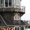
Working more slowly, but I have done a little progress on the towers. I have also redone the angles of the pinacles of the top towers.
/Matti
-
tarbrush reacted to marktiedens in Vasa by marktiedens - FINISHED - Sergal - scale 1:60
Starboard hand rails done!also added some nice black nails to the wales - seems to add a little character to the hull to me.
-
tarbrush reacted to shipmodel in Queen Anne's Revenge 1710 by shipmodel - FINISHED - 1/36 scale
Hello to all -
Those of you who followed my building of the Swan 42 racing yacht may experience some temporal whiplash as the Wayback Machine moves the shipyard some 300 years into the past. Even though the scale will be about the same, the materials, methods, and style will have little or nothing in common with the last project. We leave the clean lines and millimeter accuracy of a rich man's toy for the rough outlines and incomplete draughts of a pre-Colonial pirate ship.
Queen Anne's Revenge was the flagship of the notorious pirate Edward Thatch (incorrectly called Teach), known as Blackbeard. In barely more than a year and a half, from the summer of 1717 to November 22, 1818, he and two other pirate leaders put together a large fleet that took numerous merchant ships, looting them and holding any worthwhile captives for ransom while taking any willing sailors into his piratical crew. He was hardly the most notorious or bloodthirsty pirate, but he captured the popular imagination with his large fierce black beard and his habit of placing lit rope matches for his weapons into his hair during a battle.
The origins of the ship herself are not definitively known. It is thought that she was built in about 1710 as a small frigate of about 300 tons known as La Concorde, with her first cruise as a French privateer during Queen Anne's War in 1711. When the war ended in 1713 with the Treaty of Utrecht her owners sent her into the slave trade. She made two profitable cruises between 1713 and 1717, taking slaves from West Africa to the French colonies in the Carribean and capturing prizes on the return leg back to France. On November 28, 1717, during her third slaving cruise, she fell afoul of Blackbeard with two armed sloops. Her crew was sick and many of the cannon had been removed to make more room for slaves so she was captured easily. Below is a drawing of a similar light frigate from the early 1700s.
After renaming her Queen Anne's Revenge and adding significantly more cannon, she became Blackbeard's flagship and was used to capture numerous ships and even to blockade the port of Charleston for a week. Turning north from there in company with several smaller pirate ships on June 10, 1718 they tried to enter a shallow anchorage known as Topsail Inlet (or Old Topsail Inlet), now called Beaufort Inlet in North Carolina. Although several other ships entered safely, the larger Queen Anne's Revenge grounded on the sand bar at the entrance, as did another ship that came to her aid. After removing the valuables she was abandoned and left to the cruel mercies of the sea. Blackbeard himself lasted barely another six months until his death in November of 1718 during a battle with the Royal Navy.
The ship was rediscovered in 1996 and is now being excavated underwater in project managed by the North Carolina Department of Cultural Affairs and the North Carolina Maritime Museum, part of East Carolina University. Numerous artifacts, including several cannon, coins, navigational equipment, and hundreds of everyday items have been recovered and are being conserved. You can see photographs of the artifacts, view interactive maps of the ship's history and the wreck site, and read the archaeologists' and researchers' detailed reports if you go to the Queen Anne's Revenge website at http://www.qaronline.org/Home.aspx It is a little gem of a site and well worth looking into.
I have been asked to build two display models of the QAR for the Maritime Museum. They will be at the large scale of 1:36, yielding a model of some 48" LOA from the tip of the jib boom to the ensign staff at the stern. It will rise some 44" from the keel to the main truck with a main yard of some 22" with stunsail booms rigged but not extended. The hull is to be solid below the gun deck but open and fully detailed above. She is to have a full suit of sails with all sail handling lines, although several will be furled so the deck can be more easily viewed.
There are no plans or illustrations of the ship, so her apearance is a bit conjectural. As a basis for the model I have been given two sets of plans. The first is a simple, one-page rendering of the lines and profile of a similar small French frigate which was captured by HMS Advice and which is known therefore as Advice Prize.
I am also working from a set of drawings done by Jean Budriot of yet another light French frigate of the period known as Le Mercure. He has written a monograph that is illustrated with numerous detailed drawings of all of the bits and pieces of the ship including several profiles, cross-sections and longitudinal sections, and sail and rigging plans. However, as is his custom, there is no station lines plan from which to derive the hull shape.
These two sets of plans have to be reconciled, not only with each other, but with the known historic facts. For example, it was reported in contemporary accounts and court-martial testimony that the Queen Anne's Revenge had 20 large cannon on board when she went down. Le Mercure is pierced for 10 guns on each side, but the Advice Prize has only 9. The Mercure drawings have the channels for the fore and main shrouds set below the gunports, while the Advice Prize has them above. Le Mercure is shown with a square, open beakhead bulkhead, while the plans for the Advice Prize shows a closed in forecastle. At the stern Le Mercure has a large quarter gallery, rather than the small quarter badge of the Advice Prize. But that quarter badge is set very high, with an indication that the Advice Prize had a poop deck above the quarterdeck. These and many other details, large and small, will have to be reconciled as construction continues.
To begin with, a tenth gunport was added to the Advice Prize and their spacing was adjusted accordingly. The quarter badge was lowered and it is this resulting profile that will be used to build the models.
On this plan you can see a horizontal red line. This is my line of demarcation between the solid hull below and the open gundeck above. It is set at the level of the gundeck for the forward four ports. A tapered piece will be added at the rear half of the ship to account for the sheer rise of the gundeck towards the stern. But this line is also used as my registration plane for setting up the templates for the hull shape at the various stations shown on the plans.
As I was working out the hull construction the first of what will surely be many problems arose. In the scale that is required, the maximum breadth of the model works out to just over 9 inches and the station lines work out to, mostly, 3 inches separation. To work from the centerline I would need wood of at least 4.5 inches wide and 3 inches thick. However, wood of that size is not easily or inexpensively acquired. Instead, I found basswood planks 4 inches wide and up to 2 inches thick. I decided therefore to piece together the hull.
As you can see in the wood blocking plan below, I started with a vertical central piece 3/8" thick to match the width of the keel. This was sandwiched on each side by a vertical lift 1/2 inch thick, then by the side pieces whch would be cut to the profiles of the appropriate station lines from the plans.
As usual with vertical station line lifts, they were cut to the profile of the appropriate station line. For each three inch station segment a two inch lift and a one inch lift were used. I also decided that the hull should be partially hollow, not only to reduce weight, but to give the stresses somewhere to go other than outward when the wood swelled with changing humidity. My solution was to take each lift and cut out the center, leaving a crescent of wood about 1 inch thick. Construction began with the gunport deck piece cut to shape and the three vertical central pieces glued to it using carpenters' squares for alignment. Then the station line lift crescents were glued in place and secured with dowels. Here you can see the first three segments glued and pinned, with the fourth made ready for installation.
This was continued from the center out to the bow and stern, with the final lifts left solid and clamped to the growing hull block. The completed hull block was left to dry for a week before the bamboo dowels were trimmed off.
Now the carving and shaping had to begin to reduce the stepped shape of the lifts. The model is so large that the usual woodworking tools were inadequate in any reasonable time frame. I therefore purchased an angle grinder and set it up with coarse 50 grit sanding discs. This was followed by a random orbit sander, also with coarse grit paper.
As you can imagine, this makes a hellish racket and leaves a hellish mess, Eye, ear and respiration protection are a must, and if you are not going to do all of it outside, you need three other things - an empty room in the basement; a big shop vacuum; and most importantly, an understanding wife. I am glad to say that I have the first two and am blessed with the third.
In this photo you can see how far the shaping has progressed. From here there still has to be a lot of hand work that is checked and rechecked as usual with station line templates. The next segment will take us through that process.
Be well
Dan
-
tarbrush reacted to shipmodel in Queen Anne's Revenge 1710 by shipmodel - FINISHED - 1/36 scale
Good day to all -
This segment will be a bit of a detour from where I left the hull construction last time. The sheer size of the model means that I have to work on it in the basement of the family’s weekend house near Albany, NY. There is no way that I can fit it into the shipyard in the Brooklyn apartment, which is a converted walk-in closet. I haven’t been up to the house in several weeks, so I am working on smaller pieces here in the city that can be added later. The first of these are the ship’s boats. As always, there are half a dozen good ways to get the job done. Here is mine. The recitation is quite long, so I have broken it up into two parts. The first will cover the shaping and planking of the hull, and the second will finish with the fitting out of the interior.
The Mercure drawings that I am working from include plans and schematics for two boats, a large launch (boat 7) and a sleek pinnace (boat 6). Here I will be building the launch. The drawings had been sent to me as .tif files, so it was easy to drop them into Photoshop and start manipulating them.
First I used the rule stick in the hand of the little gnome dancing on the page to scale the drawing to the size of the model. I cropped and copied the forward and aft station lines portions of the plans and moved them to a new blank image. Identical square outlines were superimposed around the two drawings to give them the same registration planes and centerlines.
Once I was happy that everything was square and aligned correctly they were copied repeatedly to fill a page sized image and printed out several times to get one image for each of the 21 stations shown on the profile and cross section plans. These were cut apart and glued with spray mount to squares of 1/8” wood sheet.
The outline at each station was cut out with a notch for the keel and shoulders at the sheer. The three in the upper right are standing up because they have already had spacers glued to their back sides like the one in the upper left. These are used with the building board, which is marked out for the centerline and each numbered station.
The station formers are glued to the board and to each other one at a time with a top spacer used to keep them at the proper distance and an engineer’s square to see that they are perfectly vertical.
While the glue was drying on the developing stack of formers the two strongbacks (stem-keel-sternpost) were cut out. It is somewhat weaker to do it this way, as you end up with cross-grain on the stem and sternpost, but it is faster, and this boat is something of a test bed for techniques. For the same reason, the wood used is almost exclusively basswood. It is easy to work, glues well, and when stained correctly is almost impossible to distinguish from a close-grained hardwood.
The portion of the plans showing the longitudinal cross section was mounted on an 1/8” wood sheet which was then glued to a second sheet, with the glue placed only where the wood would be chucked. The outline of the strongback was cut out on the band saw, leaving a glued central piece to be cut last. This yielded two identical pieces that came apart as soon as the last cut was completed.
Here is the completed stack of formers on the building board with one of the strongbacks temporarily set up in the notch for the keel. It goes without saying that once the stack was fully glued it was shaped and faired with sanding rods to get smooth curves from bow to stern.
The strongback is held vertically with small blocks at the bow and stern that sandwich the tops at the centerline. Two transom pieces were taken from the plans, laid out and cut as before, and each was test fit into the notch cut for it at the base of the sternpost. The location of the forward edge of the plank rabbet was determined and marked out on the strongback, then the small extensions that had been left above the stem and sternpost were trimmed until it snuggled down into the keel notch at the proper level.
The strongback was removed and the rabbet was carved along the line with rotary bitts, then finished with files and rifflers. The transom was planked on the outside and glued in place against the sternpost.
Now I fit the ribs to the station formers. It was a happy fact that Budriot drew the boat with a rib at each station line and a station line at each rib. To make room for them I had cut out the station formers a little inside the line, and the sanding and fairing had further reduced the breadth of the stack. The ribs were fairly thin in any case, made from wood strips milled to 1mm x 2mm (about 1.5” x 3” in scale”). These were soaked in water to soften, then bent around each former and wired in place. No glue was used.
All of the ribs were wired in place except the aftmost one at Station 21. Leaving it off gave me a little more flexibility in fairing the planks to the transom. The strongback was replaced in the keel notch of the formers and the initial two planks were shaped.
The first was the sheer strake. From the plans it measured out to exactly ¼” in width and was left full width its entire length. A strip of basswood that width and 1/16” thick was soaked for a few minutes, then shaped first at the bow, where the tip was cut and angled to fit into the rabbet. The forward few inches were steam bent using an Amati plank bender (the one that looks like a soldering iron with a nautiloid shaped head). It is 25 years old and still works a treat. Using the shoulders cut into the formers at the sheer the plank was edge bent to match the curve before being clamped and glued to each rib and the transom.
The garboard strake against the keel was similarly fitted and glued. However, when I tried to impose the required twists into a basswood plank it repeatedly splintered. I therefore used pau marfim, a California hardwood. It is also ¼” wide for most of its length but flares to about twice that at the sternpost. To accommodate this, a tapered plank was pieced in from Station 15 to the sternpost. When I was happy with the look of the shape it was clamped and glued to the ribs. Here is what they looked like with most of the clamps removed.
A word here about stains and glues. Before any piece was installed it was given a staining with a mixture of ½ clear Minwax wood stain which they call Natural, ¼ Early American and ¼ Cherry. I find this combination the best to reduce any splotchiness in the basswood and makes basswood resemble boxwood or one of the lighter cherry varieties, a look that I like a lot. However, the stain is a bit oily, so the wood has to be well wiped and has to dry for a while before normal PVA glues will hold well.
As for glue, I use a pH neutral white glue made by Lineco which I used to get from an art conservation supply house. It sets up fast and holds well, yet is still flexible for an extended time, which will come in handy later. Now I get it through Amazon where it is competitively priced with carpenters’ wood glues.
This process was repeated for the second sheer plank and the first broad strake against the garboard, but these had to be tapered to fit at the bow. I knew from test fittings with strips of paper that there was almost exactly half the space between the garboard and sheer strake at the bow than there was between these planks amidships. Therefore the next two planks were tapered for their forward three inches to that dimension. Holding the plank to the formers and letting it find its own best fit, it was evident that the tapering on the second sheer strake should come off the edge that mated with the sheer strake, while the broad strake should taper on the garboard side.
After the bulk of the wood was removed the edge was sanded to a fair curve. This spiling was all done by eye, with the curve examined from every angle and refined as needed on this and every successive plank.
Once acceptably shaped the planks were stained, then caulking was indicated by coloring the uncut edge of the plank with an indelible black marker. The planks were bent to final shape, fitted, glued and clamped in place.
With two strakes at the keel and two at the sheer, the cage of ribs had a good deal of strength and rigidity. Now all of the wires were pulled out and the developing hull was removed from the formers. I must have done a clean job with the glue because I didn’t have to pry it loose at any point.
Subsequent strakes were processed in a similar way. For clamps I used bulldog clips that had a handle piece from a second clip fitted into the top of the clip. A modified clip was used on every other former to hold the plank to the ribs as the glue dried.
Here is what the hull looked like with 8 of the 11 strakes in place. At this point the remaining space was divided into thirds as you can see from the pencil marks on the ribs. This would be filled with two standard width planks and one custom fit ‘shutter plank’ that closed in the hull.
Here is one completed side. The shutter plank location was selected to lie just under the curve of the chine of the hull, making it less visible than any other spot. It is the fourth from the keel. It is slightly wider than the other planks and flares at the stern to fill the larger space.
While it was on the formers the location of each rib was penciled onto the planks in preparation for the ‘nails’ holding the planks to the ribs.
Once the other side was closed up the hull was removed from the formers. I think the method worked quite well and resulted in a hull that is strong, symmetric, and gives a convincing appearance of an actual boat structure. The white plastic figure in the corner is useful to judge scale appearance and will appear again.
Spiling the planking by eye in this way is an acquired skill, but not difficult if each plank is critically examined and adjusted as needed. The final hull has a nice run of planking that tapers smoothly to the stem and matches, port to starboard, and even has the little variations in width that a real boat does.
In the next installment I use the penciled lines to drill the nail holes for the more than 1100 fasteners used for the hull planks. Then I fit out the interior and finish the boat.
As always, critical review by the eyes of my peers is requested. This is even more so in this case since the boat is the first generation attempt and, despite the work and time invested, may not make the final cut.
Looking forward to hearing from all.
Dan
-
 tarbrush got a reaction from NenadM in Cutty Sark by NenadM
welcome to MSW Nenad! Cutty Sark is such a beautiful ship, definitely on my list to do one day. It looks like you are off to a good start and it like it might be quite a large model. What scale are you building to? I would love to build a really big model Cutty Sark. I will pull up a chair and watch.
-
 tarbrush got a reaction from Script in Lackawanna by Script - FINISHED - BlueJacket Shipcrafters -1/8" to 1'
Congratulations Jim, she came out soooo good. I love the outdoor photos of her!
-
tarbrush reacted to EdT in Young America 1853 by EdT - FINISHED - extreme clipper
Young America - extreme clipper 1853
Part 6 – Keel Rabbet and Waterstops
The keel rabbet provided a seat for the garboard strakes – the strakes of bottom planking next to the keel. These strakes were 9” thick and were bolted through the outside edge into the keel as well as into the frames. The v-notch of the rabbet on these ships was slightly different than the 60 degree triangle of 18C RN ships. It was less sharp and deep.
(Note: Having just finished an 18th Century Royal Navy vessel and knowing there is a large following for these types on the forum, I will try to point out differences in structural design that may be of interest. To do this I will use the abbreviation "18C RN" for the earlier types.)
To form the rabbet, I used a scraper cut from a piece of stainless plate. I have a lot of these small pieces lying around and they have been useful for this. The first picture shows the scraper being roughed out with a jeweler’s saw.
The picture below shows the final filed out shape of the scraper. The cutting edge is left square - but with sharp cutting corners on both faces.
The scraper is dimensioned to ride along the bottom of the keel. The cut is finished when the scraper bottoms on the side. Both these rubbing surfaces were rounded over and smoothed to avoid marring the sides and bottom of the keel.
The next picture shows one of the first passes on the keel
The next picture shows the keel with the finished rabbet. Actually, I did not go all the way to the sharp edge at this stage. I can use this cutter later, after the frames are set to finish the rabbet – when that sharp upper corner is more protected.
I may have mentioned earlier, that these ships had no rising wood (or hogg) over the keel. Generally the frames were bolted directly to the keel with long through bolts. Because of this, waterstops were needed to prevent leakage through the joints in the keel into the hull. The rising wood effectively blocked this path in the earlier ships. Although the garboard strakes would be caulked along the rabbet, this did not seal off the keel itself. To eliminate this leakage, holes were bored through the keel at the inside of the rabbet and plugged with long fir dowels, effectively sealing off the top lip of the scarph. I decide to install these.
The first picture shows the keel being drilled through the rabbet to accept a three inch waterstop cylinder.
The next picture shows a drawn 3" dowel being test fit.
These were actually driven in with a touch of wood glue. The excess was then clipped off and the V of the rabbet formed at the ends with a razor blade.
The last picture is one of those close-ups that make me cringe, showing a scarph joint, the central wedge and the waterstop under the upper lip. This picture also shows the joint line left using the dark glue.
The slightly flat edge, left – for now - at the top of the rabbet can be seen in this picture. The picture also gives a pretty good idea of the finish left by the scraper. The rabbet has not been sanded – nor should it be – to avoid rounding over the corners.
These waterstops are a nice little detail. Of course no one will ever see them without having very good eyesight and knowing where to look. they went rather quickly, however, so the cost was small.
I guess the next work will be either the stem or the stern post.
Ed
-
tarbrush reacted to NAZGÛL in Wasan 1628 by Nazgul - FINISHED - Billing Boats Vasa 1:75
Michael, thanks for the tip. I hadnt decided on using nails, but man you got so much of her look through them!
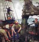
Ok, here are the most interesting pictures I managed to take. I tried to get pics that I missed looing for reference. Its really hard to get good pictures at the museum. Almost no light and the ship being so dark makes it difficult. I have worked with the pics contrast and brightness alot in photoshop, so dont take the colors as gospel.
First are hull and planking pics. The weather deck and some other details.
/Matti
-
tarbrush reacted to Script in Lackawanna by Script - FINISHED - BlueJacket Shipcrafters -1/8" to 1'
Augie,
Thanks, appreciate your comments......
But............................................................................................................................
Why did you have to reveal the old pie plate trick?????
Truth be told, that penny was extra small.....it shrank from the heat....... :huh:
Randy,
Thanks for stopping by! Appreciate your comments!
I believe I used a #72 bit....but it was so small I'm guessing....
Sjors,
Thanks! Always enjoy your comments and enthusiasm....
My laundry list has the Marseille by Mamoli, a couple railroad engines, a Sopwith Camel and the Confederacy(already got the brass cannons and figurehead from Chuck's company) but will wait for Augie to finish his before even opening the box!
I'm going to put a couple finish pics here as well...
Thanks to all who looked in and commented or 'liked' my little tugboat!
-
tarbrush reacted to marktiedens in Vasa by marktiedens - FINISHED - Sergal - scale 1:60
Finally got the port side gallerys done.
Mark
-
 tarbrush got a reaction from FrankWouts in HMS Prince 1670 by Spiderpig - FINISHED - Constructo - Scale 1:61
Beautiful work Adam! Prince is such a gorgeous ship, I look forward to following your progress.