


RMC
-
Posts
933 -
Joined
-
Last visited
Content Type
Profiles
Forums
Gallery
Events
Posts posted by RMC
-
-
Aaah! I hadn't yet looked at the other blocks. Thanks Jose. Back to the drawing board

-
Thanks for the warning Arthur. Having earlier drilled out a couple of blocks on site, it's something I don't wish to repeat. With the block, I think I'll go for the larger one as it seems to me more likely that the label is wrong than the drawing.
-
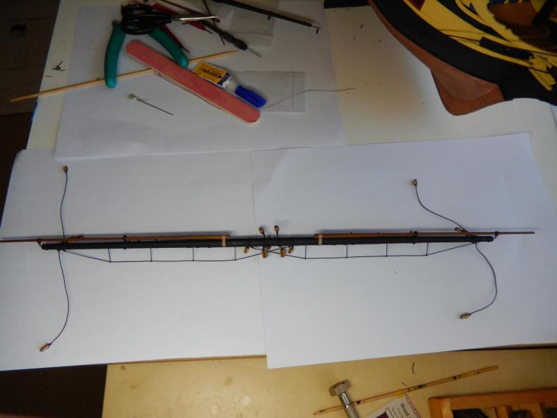
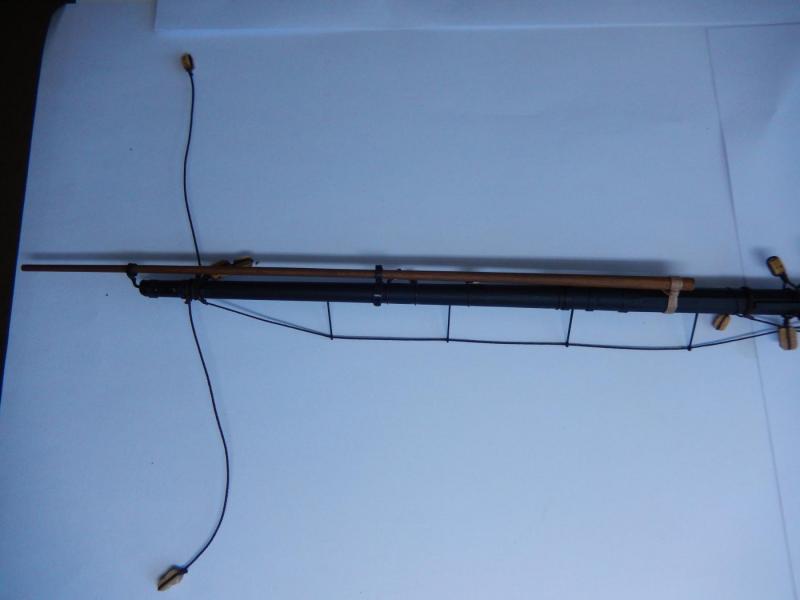
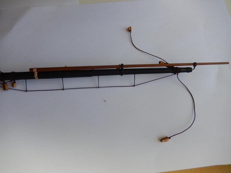
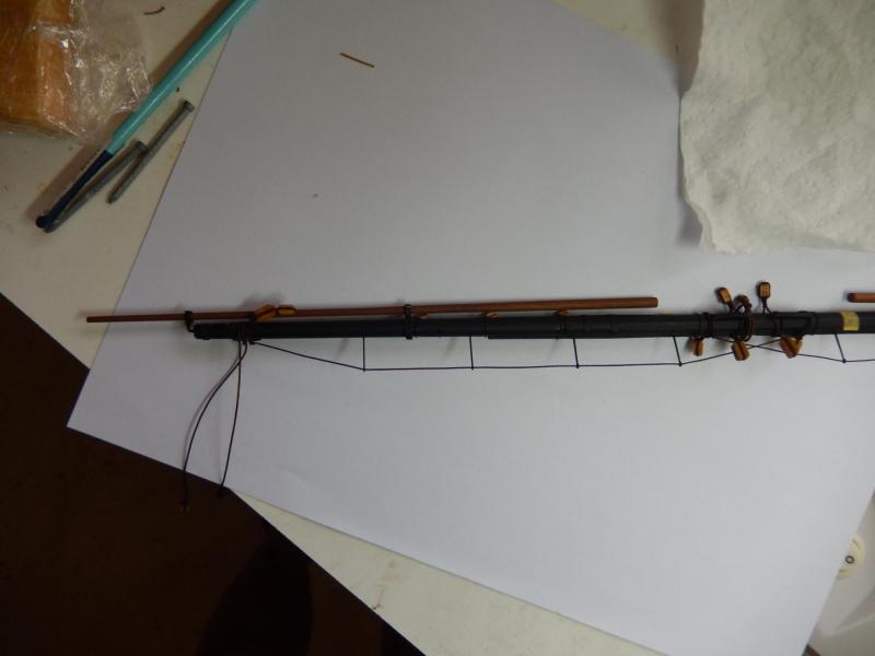
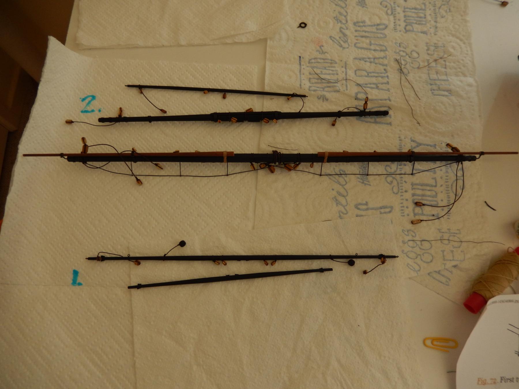
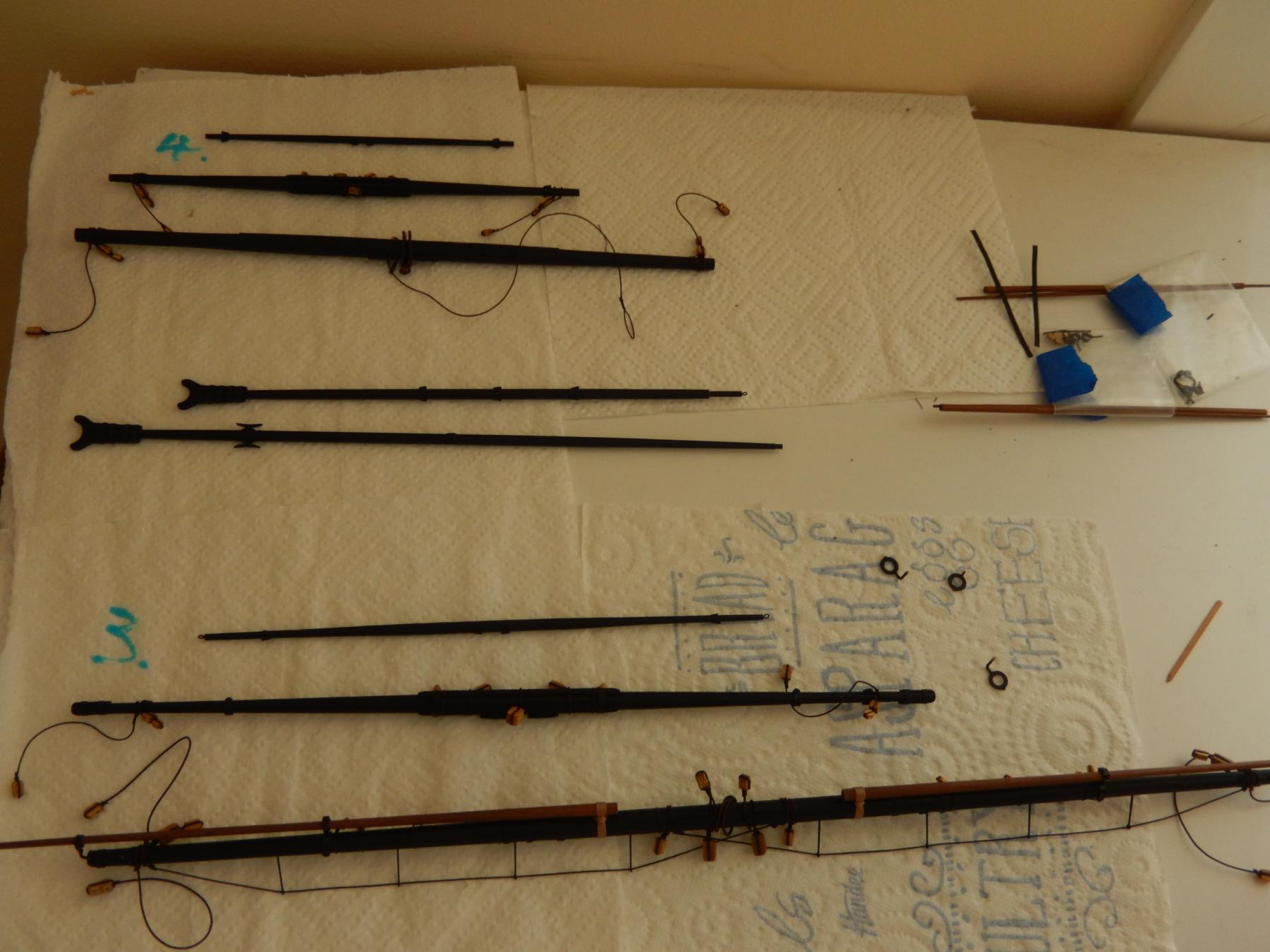
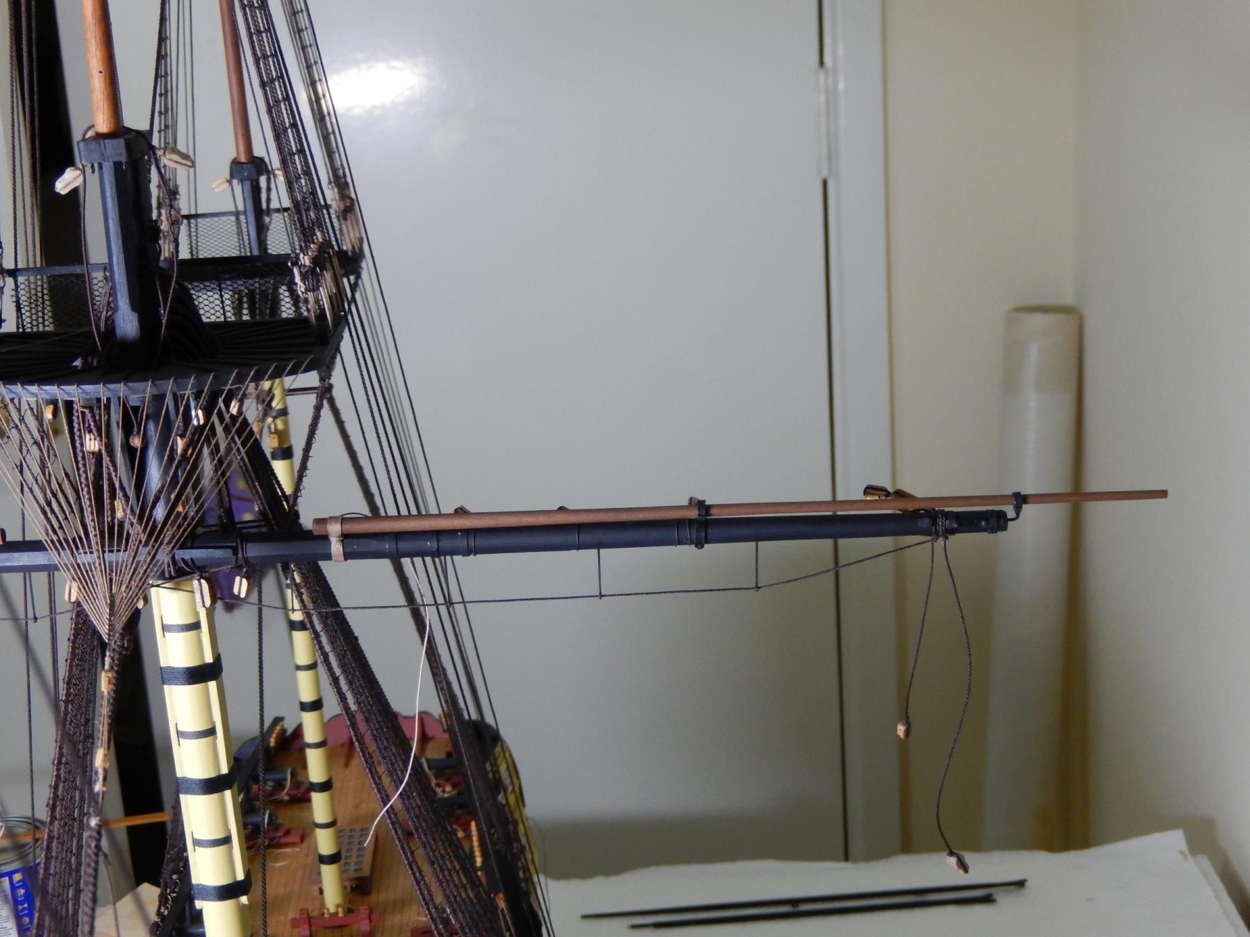
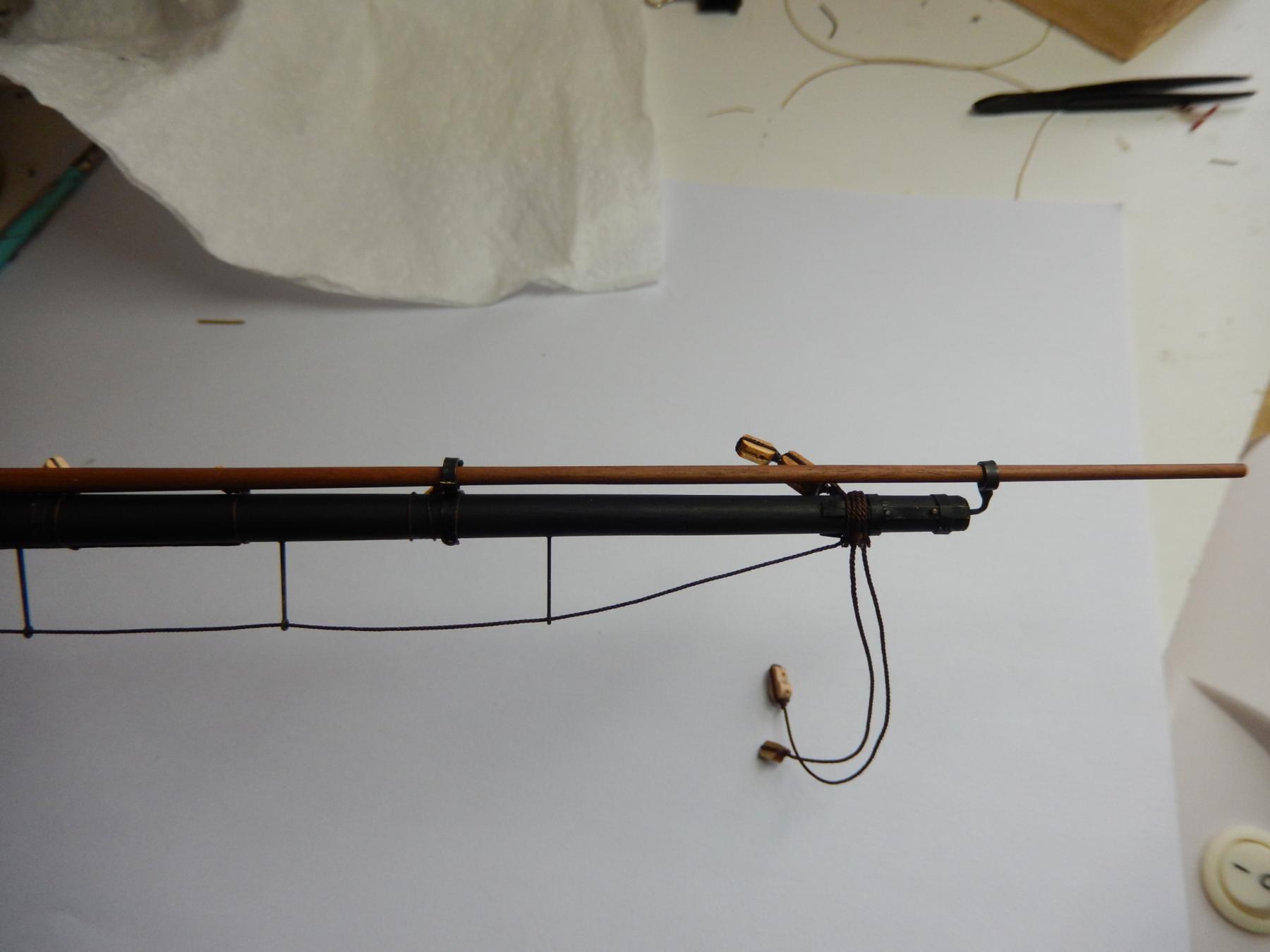
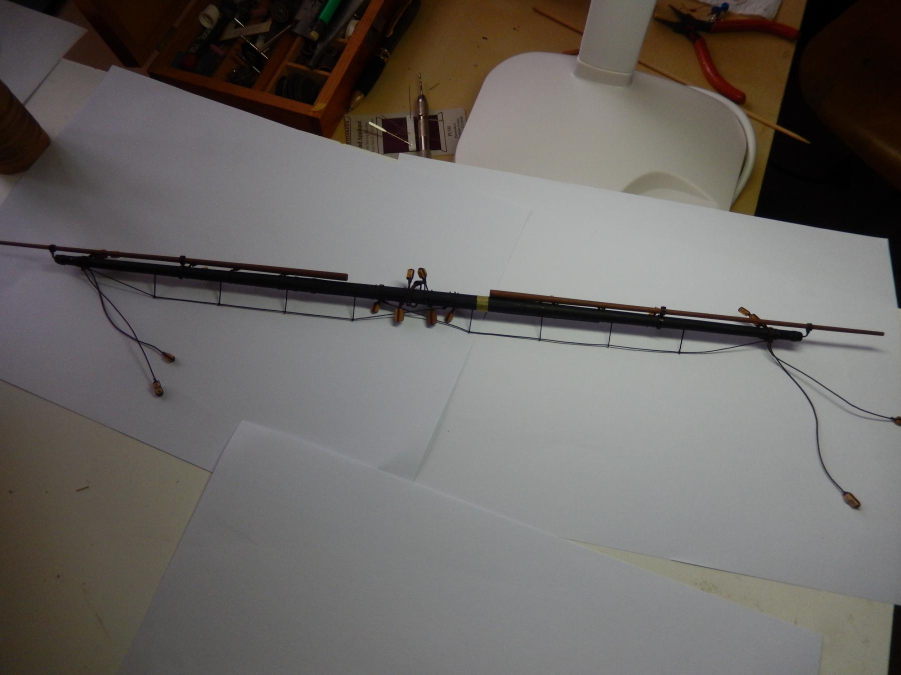
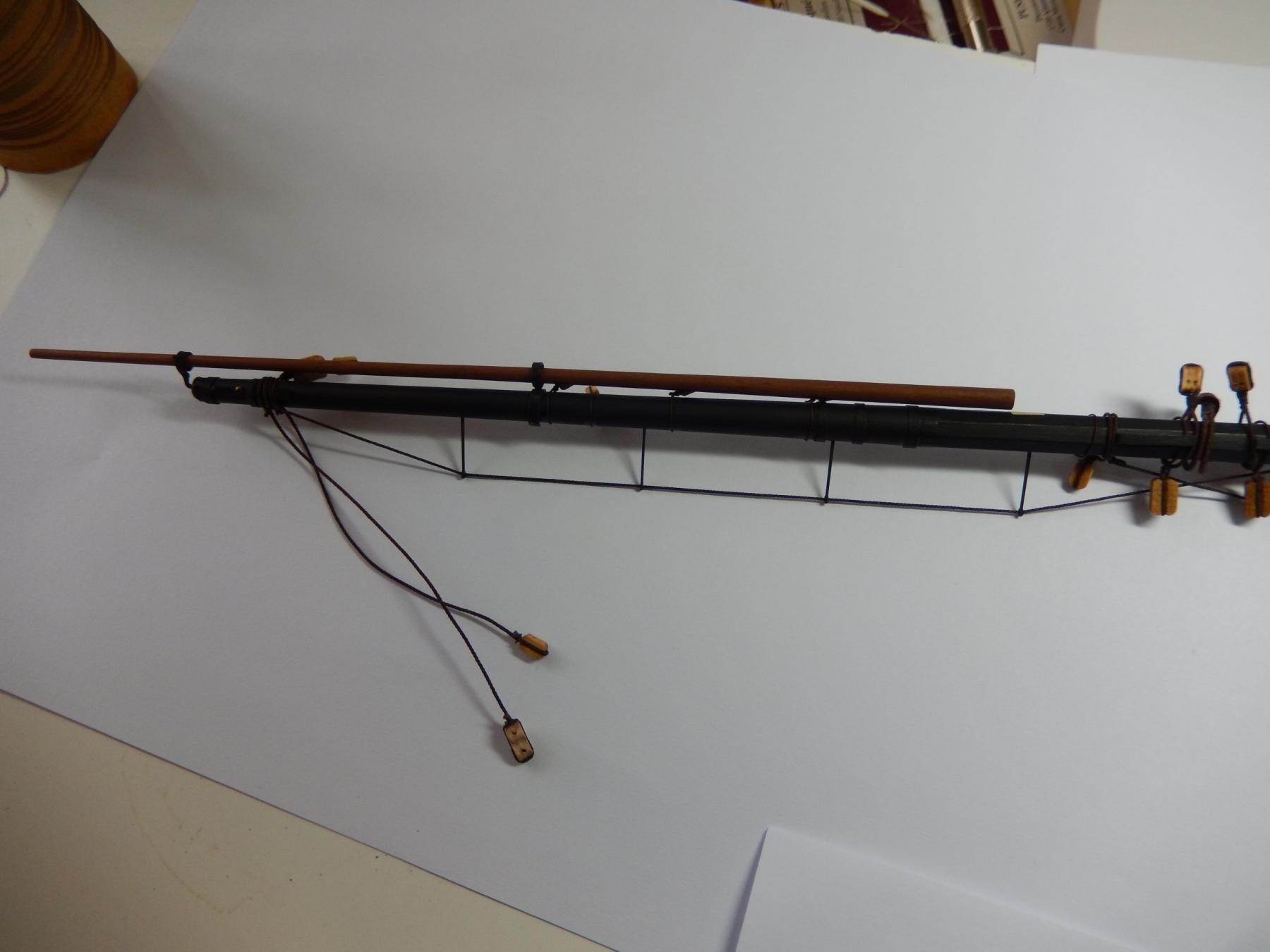
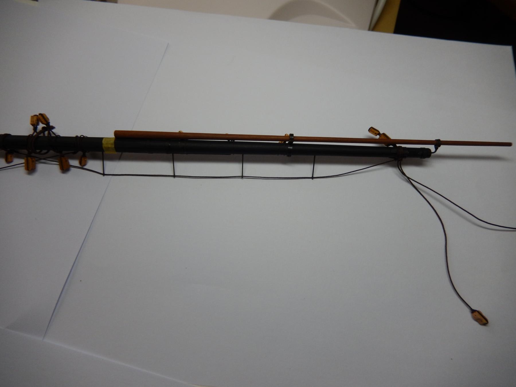
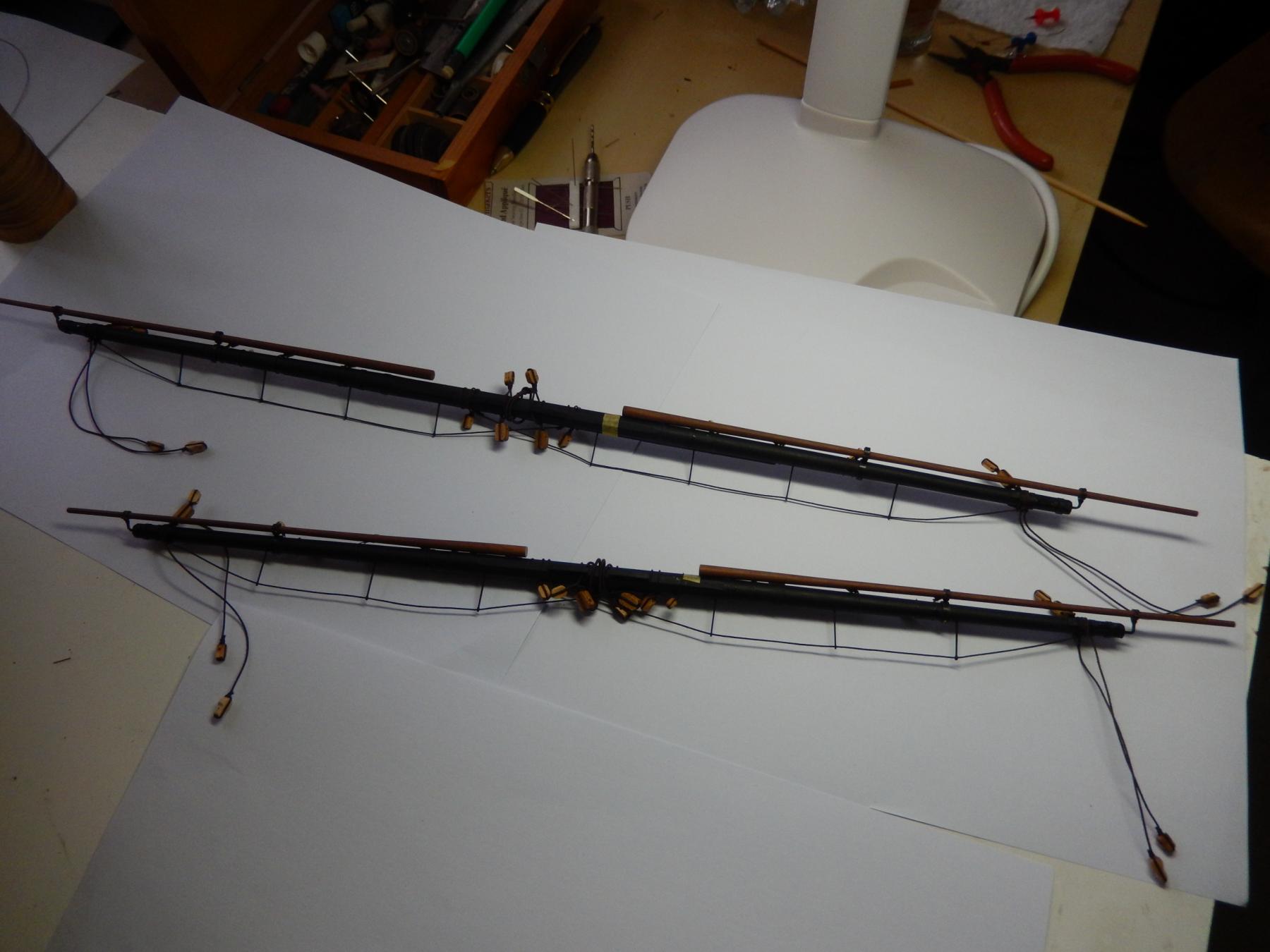
Here are photos of the yards as they are now. Almost all have their blocks etc attached. The holes for the footrope stirrups are drilled, ready for the foot ropes - I will put these on last as they are quite fragile.
The two yards labelled 1. are for the sprit sails, and 2. the foremast yards.
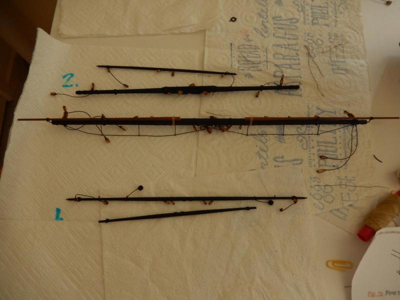
3. the main yards. 4. the driver gaffs and the mizzen yards.

I didn't make as much progress as I'd hoped as there were other things to do.
The last couple of years I have photographed Pigeon House mountain (named by Captain Cook) on the eve of the summer solstice. Missed out the year, but here are two taken on Christmas eve.

This is one of the many Green Islands on our east coast. (I must to something about the rotten power pole. Perhaps termites are the answer. )

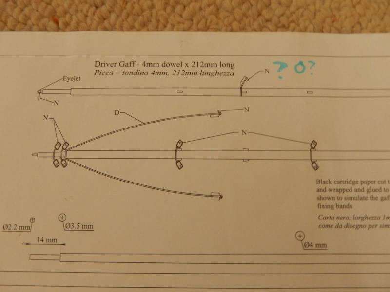
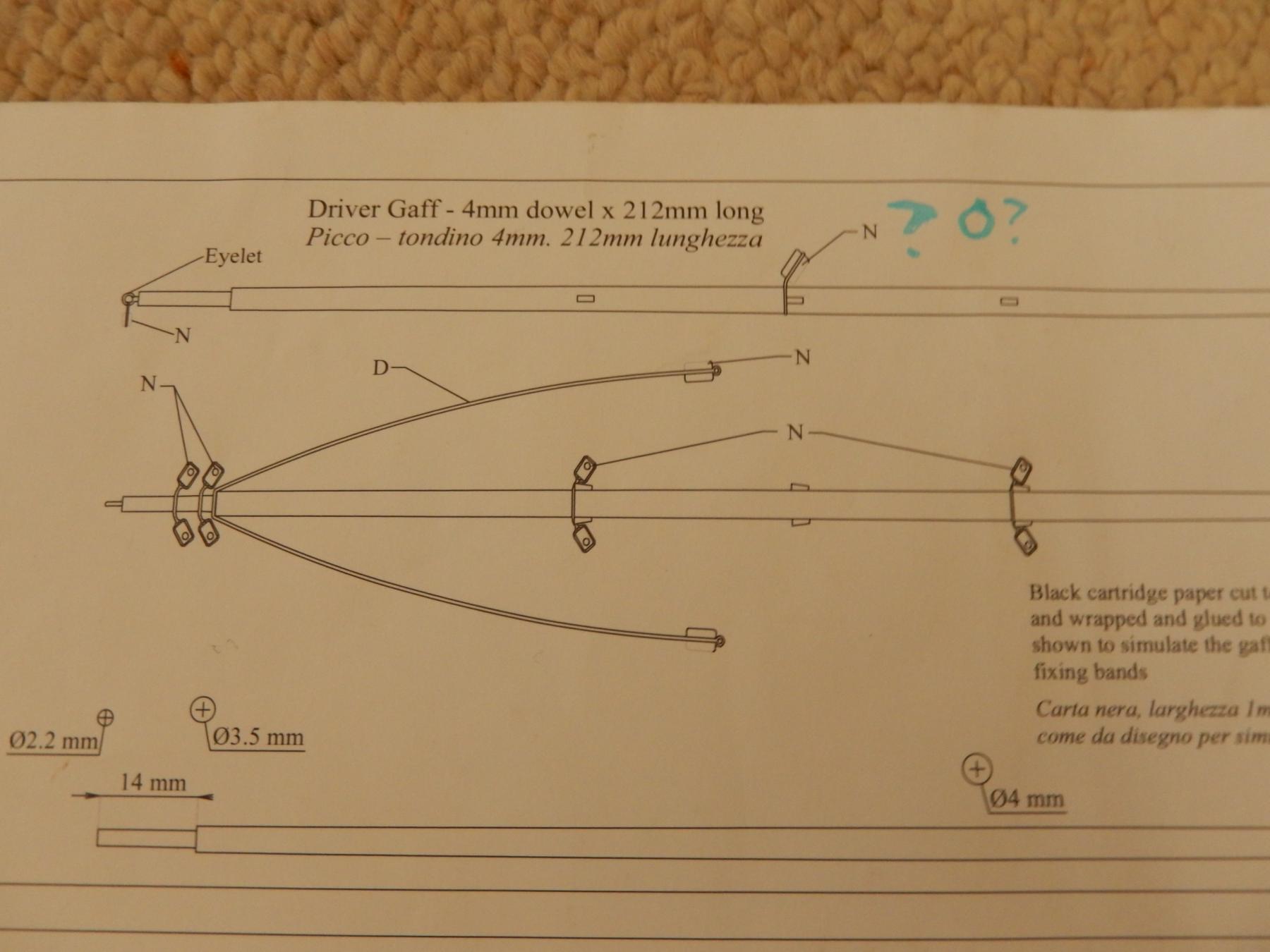
I forgot about the possible errors in the plan. Now I can only find one. For the driver gaff, the plan specifies a 3mm block (N). Drawn on the plan is a 5mm block (O). Does it matter?
Happy New year to all.
-
Sorry for my delay in replying Jose. Thanks for the information. There are a couple of other possible mistakes in the plans' rigging specifications that I have come across. I would be grateful for your views. I have a few photos of those and of the progress I have made on the yards. I will load them when I get a chance. Doing something about an out-of-control garden has precedence. At least now the various blocks etc are attached and the yards are now all but complete. I am rather sick of tying knots
-
Thank you Jose. All the best to you and your family.
-
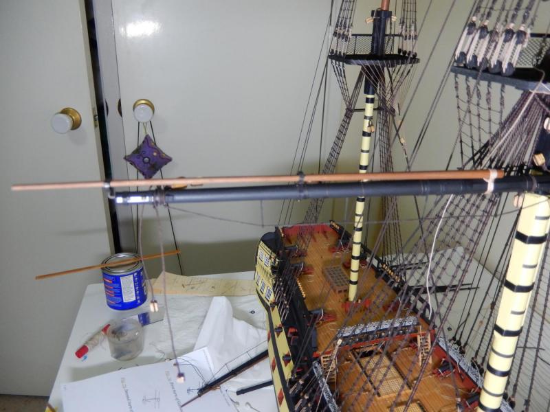
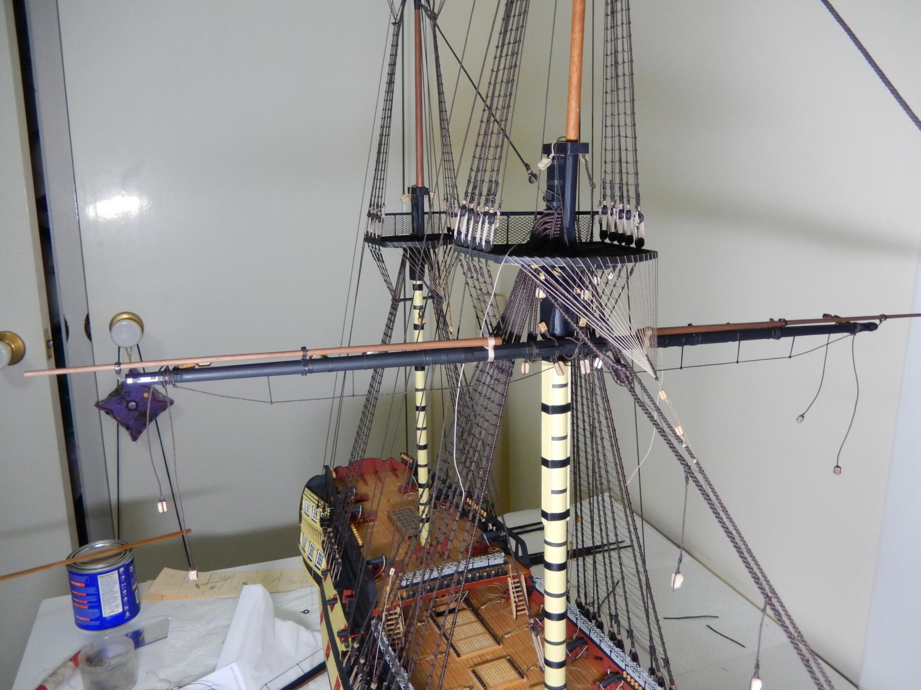
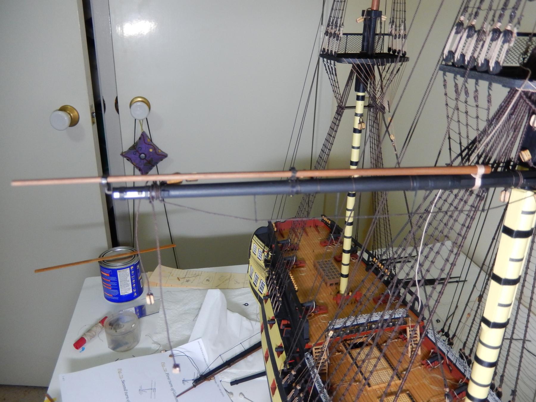
The main yard is finished - finally. The stunsail booms are mounted, and I hope all the blocks are in the right places. Out of curiosity I mounted the yard onto the main mast to see how it looks. A brass pin in the yard stuck into a hole in the yard does the job. To my very pleasant surprise (what with all the bits and pieces hanging on it) it was perfectly balanced. Fancy that.
Here it is on the model.

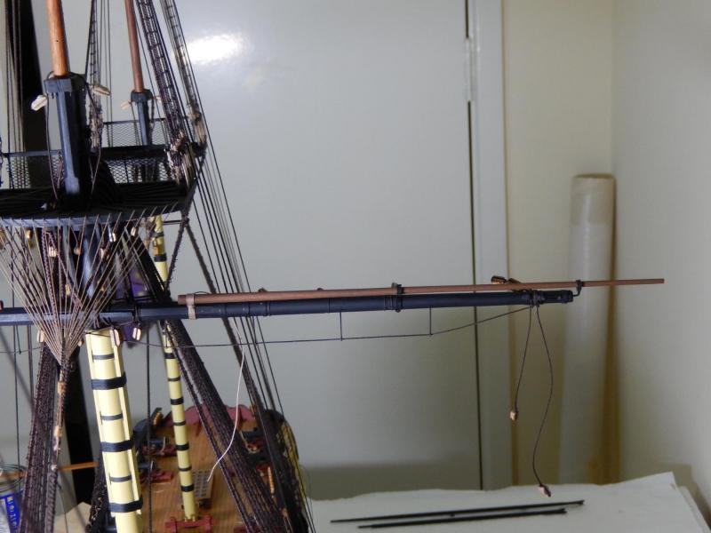
and off the model.
We are off to the coast south of Sydney on Friday for Christmas and New Year - back in mid-January. I hope I may finish another yard or two while away - among other things. I would like to thank members for the kind comments, the help, the 'likes' and the encouragement given me during the year. I had thought to mention names, but I would be sure to miss someone, but I'm sure you know who you are.
Have a happy Christmas and a happy, healthy and prosperous New Year.
Bob
- Beef Wellington, kier, russ and 4 others
-
 7
7
-
-
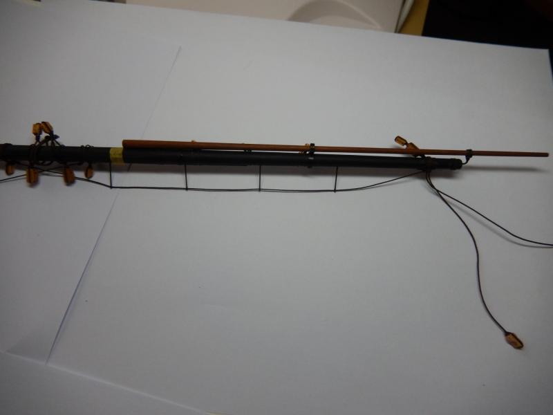
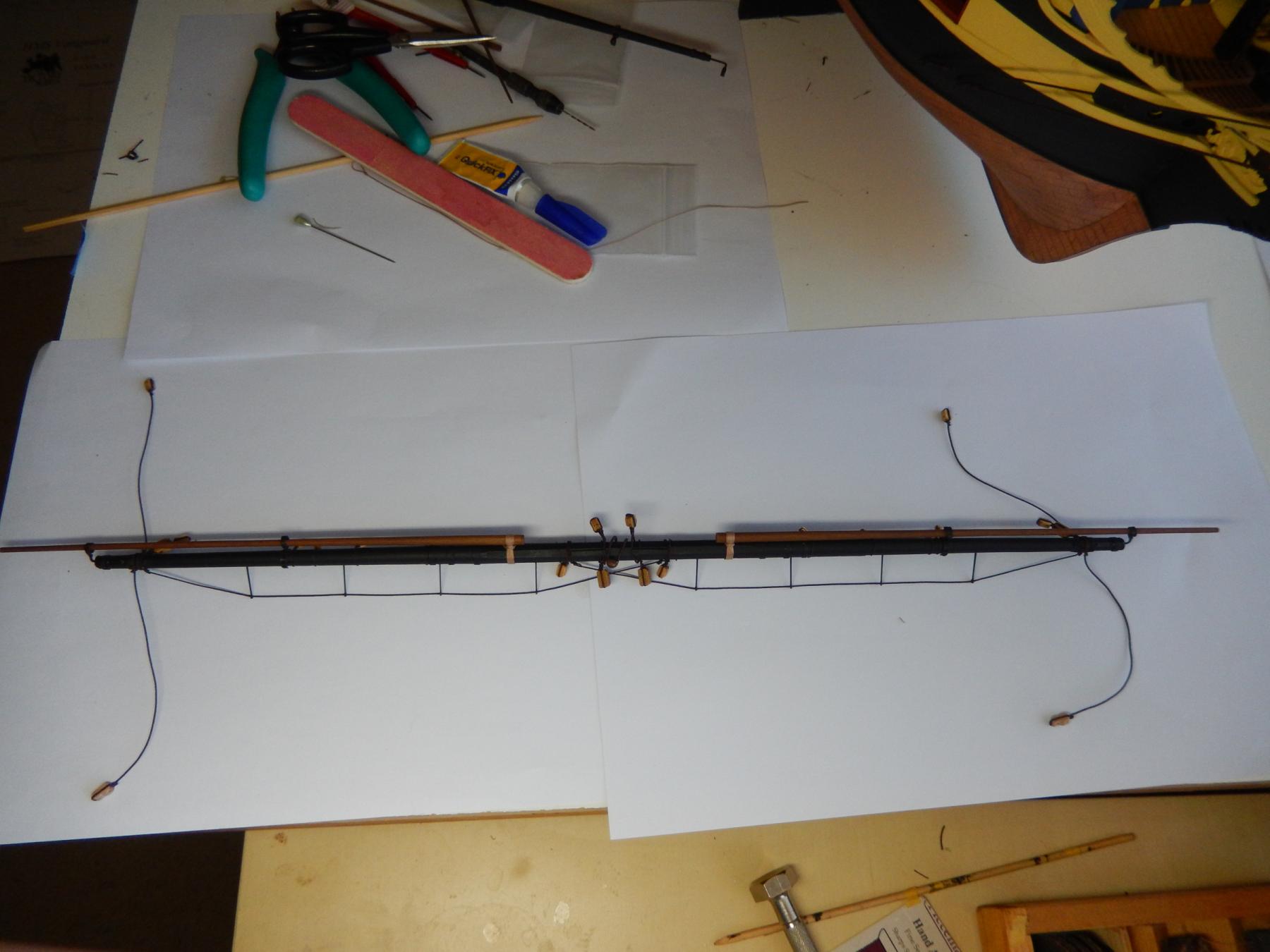
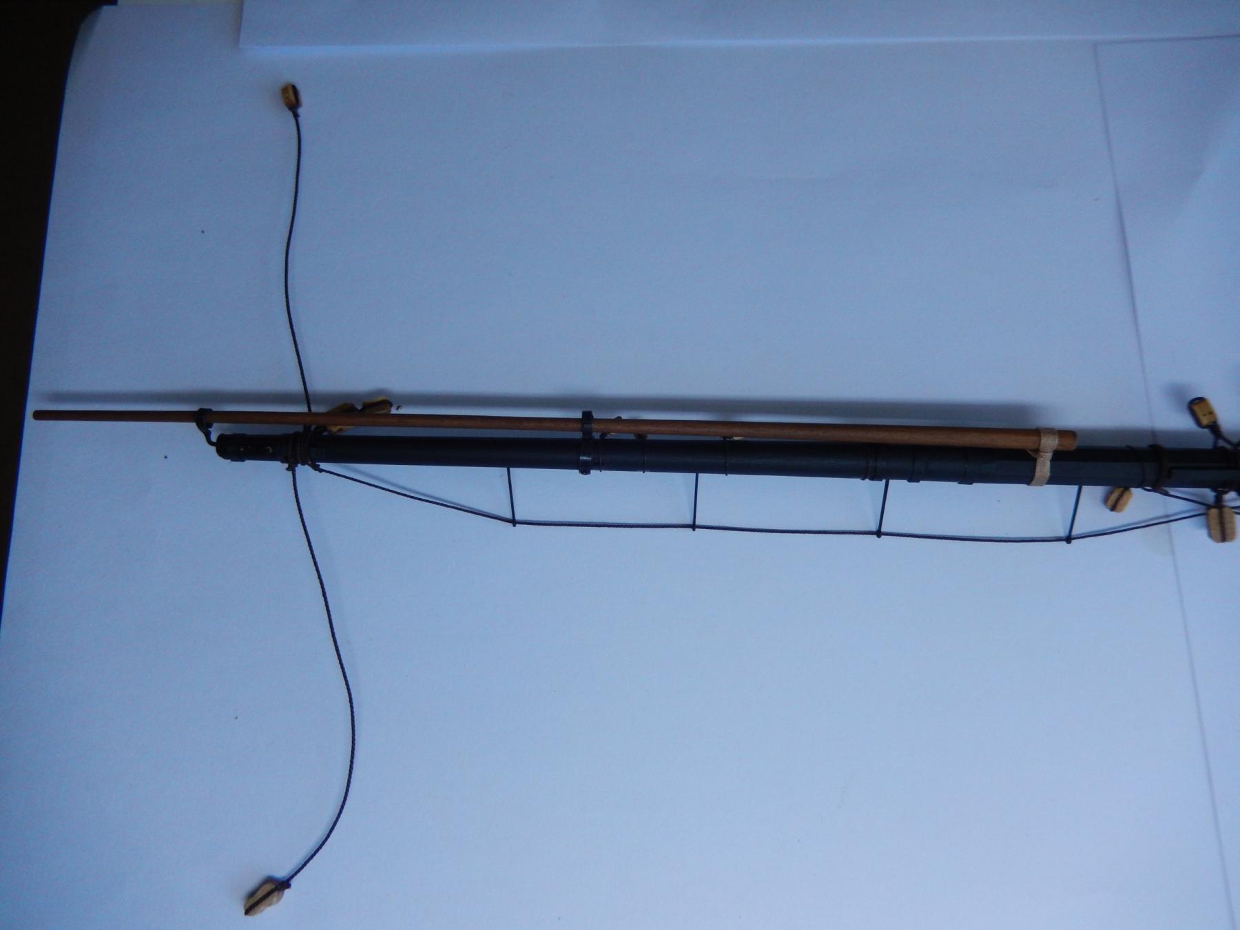
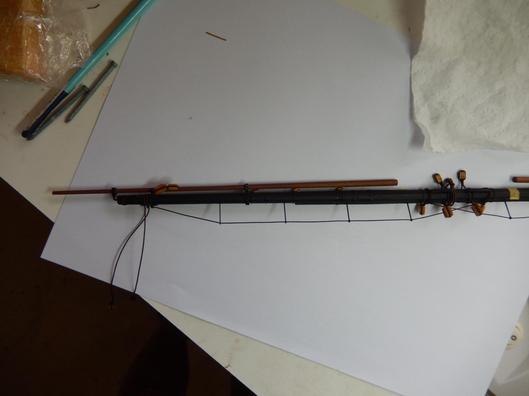
The fore and main yards are now more or less finished. The stunsail booms are to be finally fixed (to do later next week) , but all the rest of the bits and pieces are complete. I have tried to show as much detail as possible in the following photos. I took them a few days ago, and now realise I didn't label them, so I'm not sure which is which - anyway, it's the principle that is important.
 I've certainly learned a few things in doing these two yards. For those who may find my experience useful I suggest:
*first, drill the holes ready for the footrope stirrups;
*second, fit the stunsail boom rings; (I have not used the kit fittings which are quite poor. I show how I made replacements earlier in this log.)
*third dry-fit the booms; and
*last, fit the various blocks having made sure the dry-fitted booms do not foul them. (Something I wish I had foreseen.)
Hindsight is a wonderful thing.
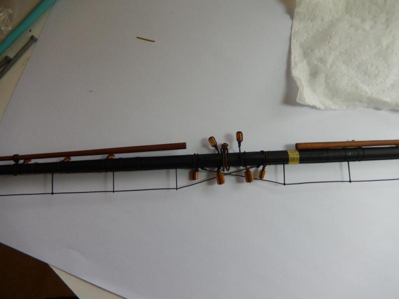

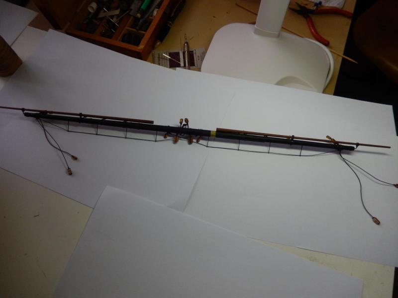

Here are both the yards.
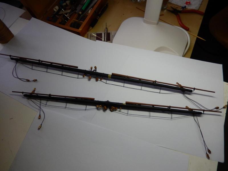
I just noticed a couple of the foot ropes look as if they are a little tight. In fact they hang quite nicely. A little dilute PVA glue does the trick.
- Beef Wellington, mort stoll, russ and 4 others
-
7
-
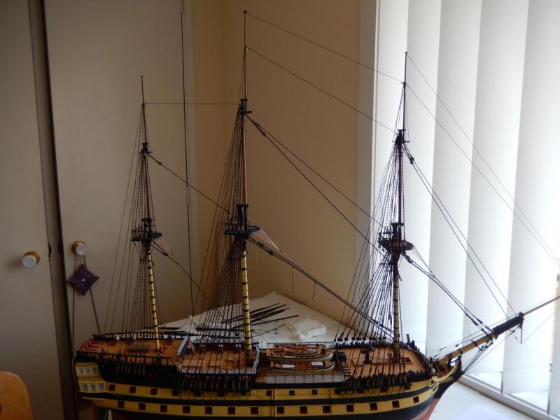
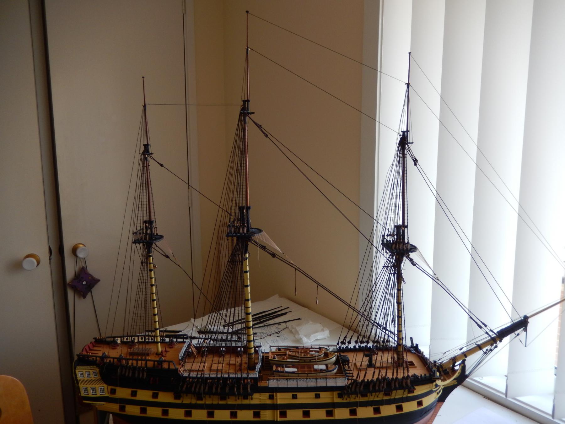
The running rigging is now all but complete. Royal back stays are to come. It's not urgent, and I'm not sure whether I have enough Syren thread for them and some of other things I need to do. If necessary I will order some more thread, but Christmas/holiday time is not the time to do it.
This is how things look at the moment.
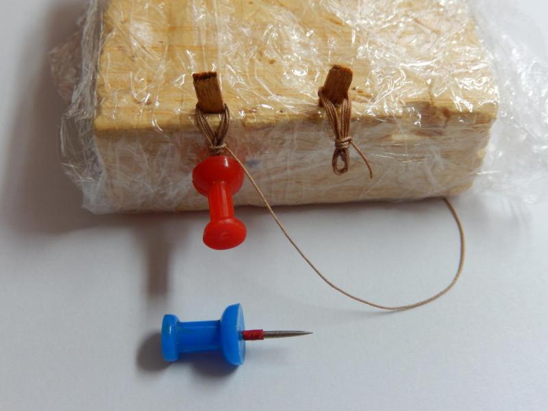
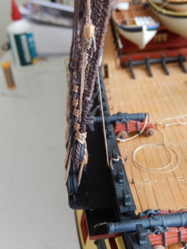
I am now finishing off the main and fore yards (photos later), and while doing that, unfortunately my thoughts have turned to rope coils. After quite a few experiments, this is the method I have used for the coils for the timber heads.
I have wrapped a piece of balsa in cling wrap (preventing the thread from sticking). Having measured the required length of the coil, I have simply stuck a drawing pin into the balsa at the correct height for the drop. The bit of wood at the top is about the same size as the timberheads and is simply a piece of scrap, sharpened at the bottom and stuck into the balsa.
To enlarge the lower part of the coil, and to prevent the thread from sticking I have put a small (red) piece of electrical insulation over the pin. I would have preferred something a bit thicker to make a larger lower coil, but I guess you can't have everything.
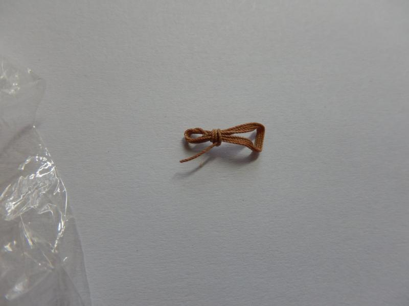
This gives an idea of how they will look on the model.

-
Thank you zappto. A bit of inspiration is good for us all.
-
Thanks very much for the encouragement Nigel. At the moment I'm getting rather tired of rigging.
Jason: in looking at the pins I agree with you. I hadn't really noticed before. Problem: the pins on the other bitts are well and truly glued - so in a manner of speaking, I'm stuck.

-
-
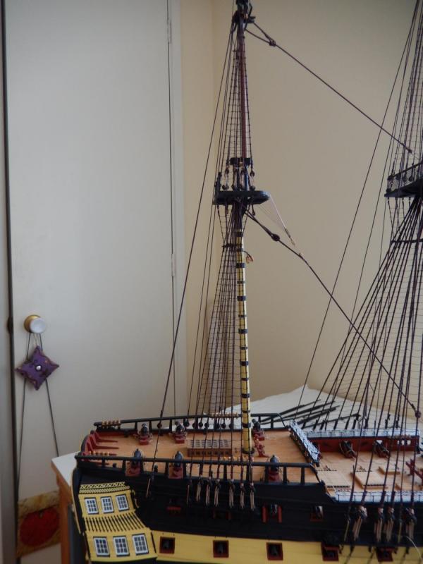
The fore and mizzen top gallant back stays are now finished and the main, almost.
Here is the foremast. The backstays are not finally made off, and the last two, at the far left of the photo will be left as is for the time being. They are the ones most likely to get in the way of later rigging and may be easily moved if necessary.

Here is the mizzen. Ditto the preceding remarks.
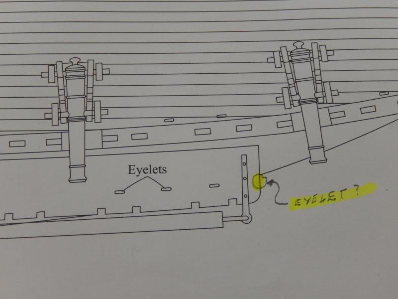
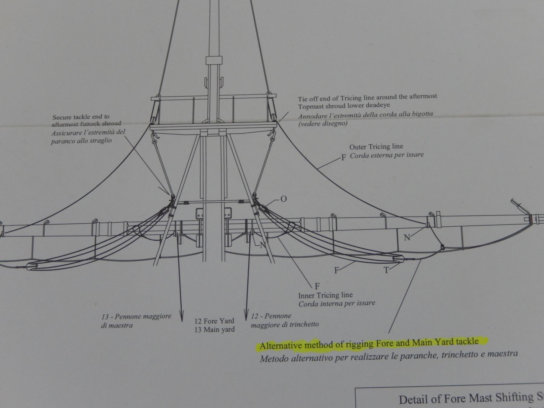
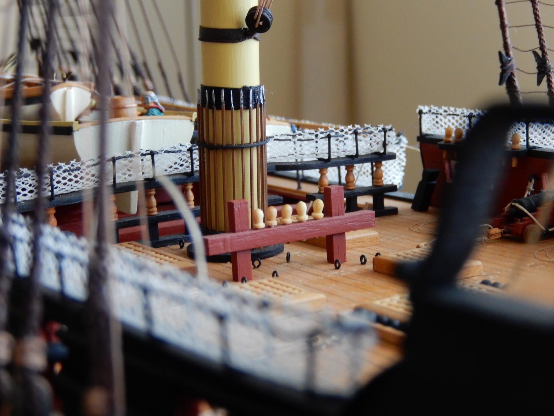
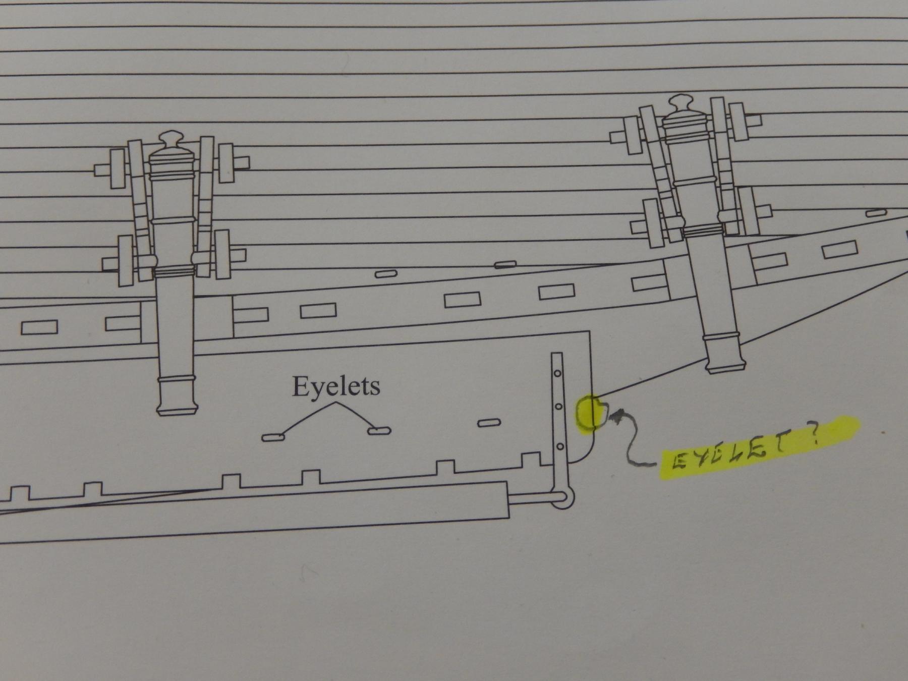
I may have belatedly found the reason for the omission of the eyelets on the forward channels mentioned in an earlier post. In looking more carefully at the plan (9) - always a good idea, though I often ignore it - I came across this! It seems rather (needlessly?) complicated and I think I will continue to ignore it. I have in any case put the extra eyelets on the channels.
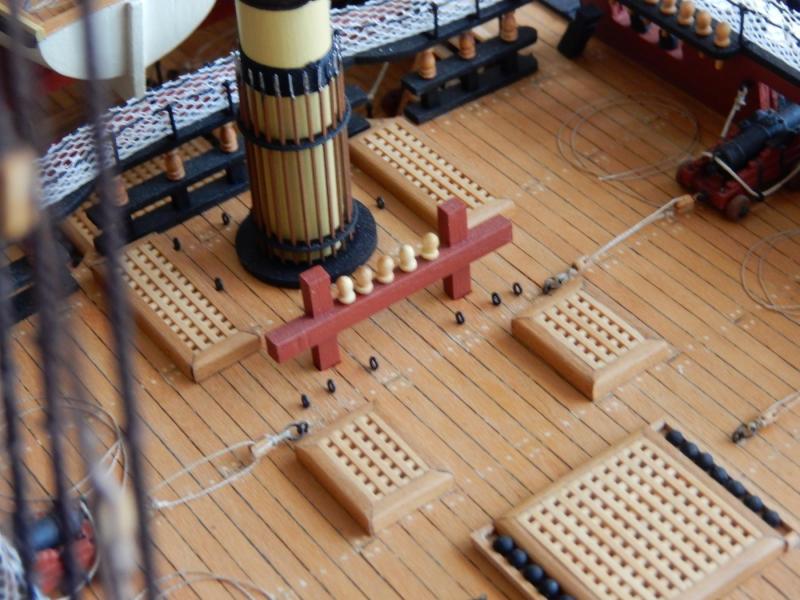
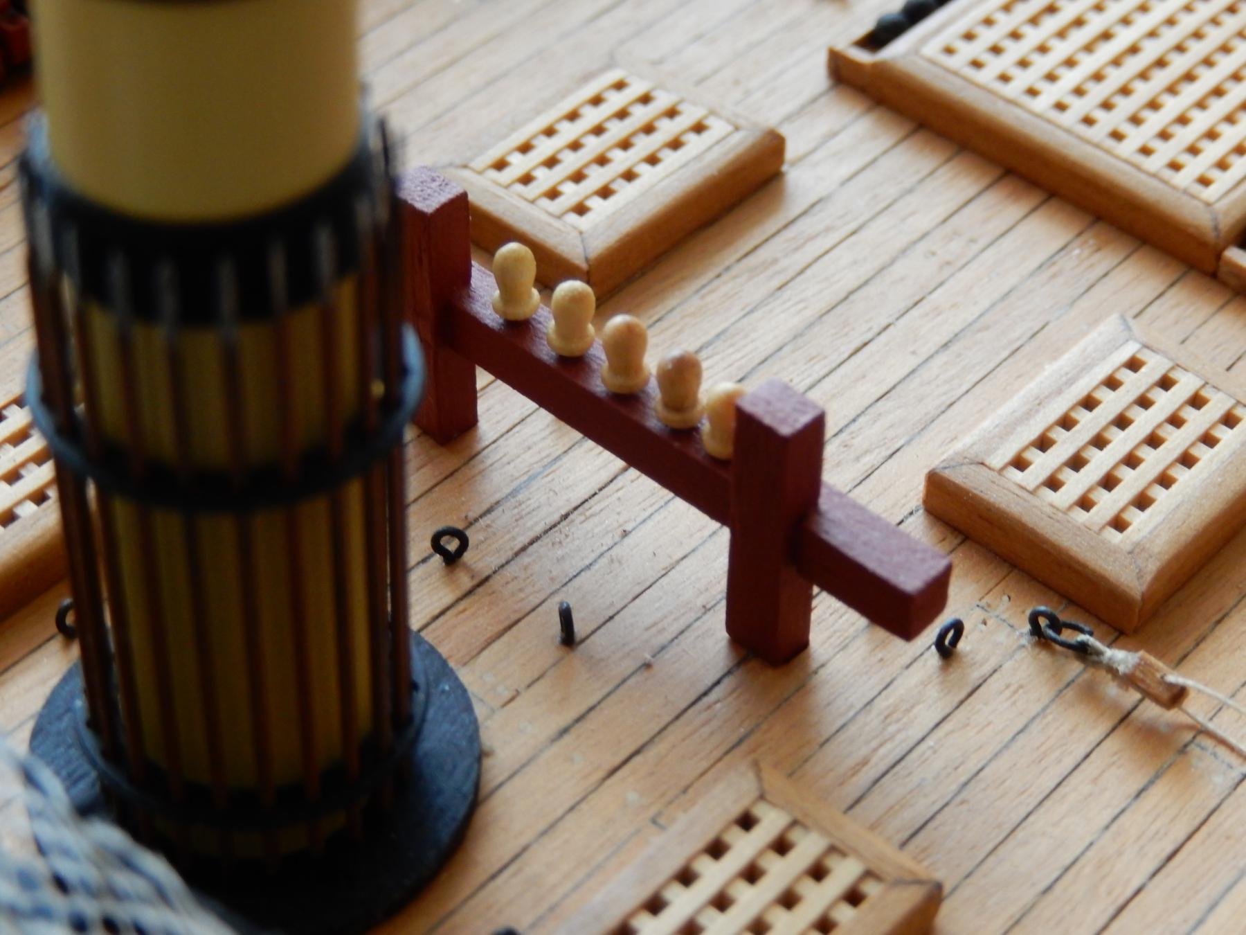
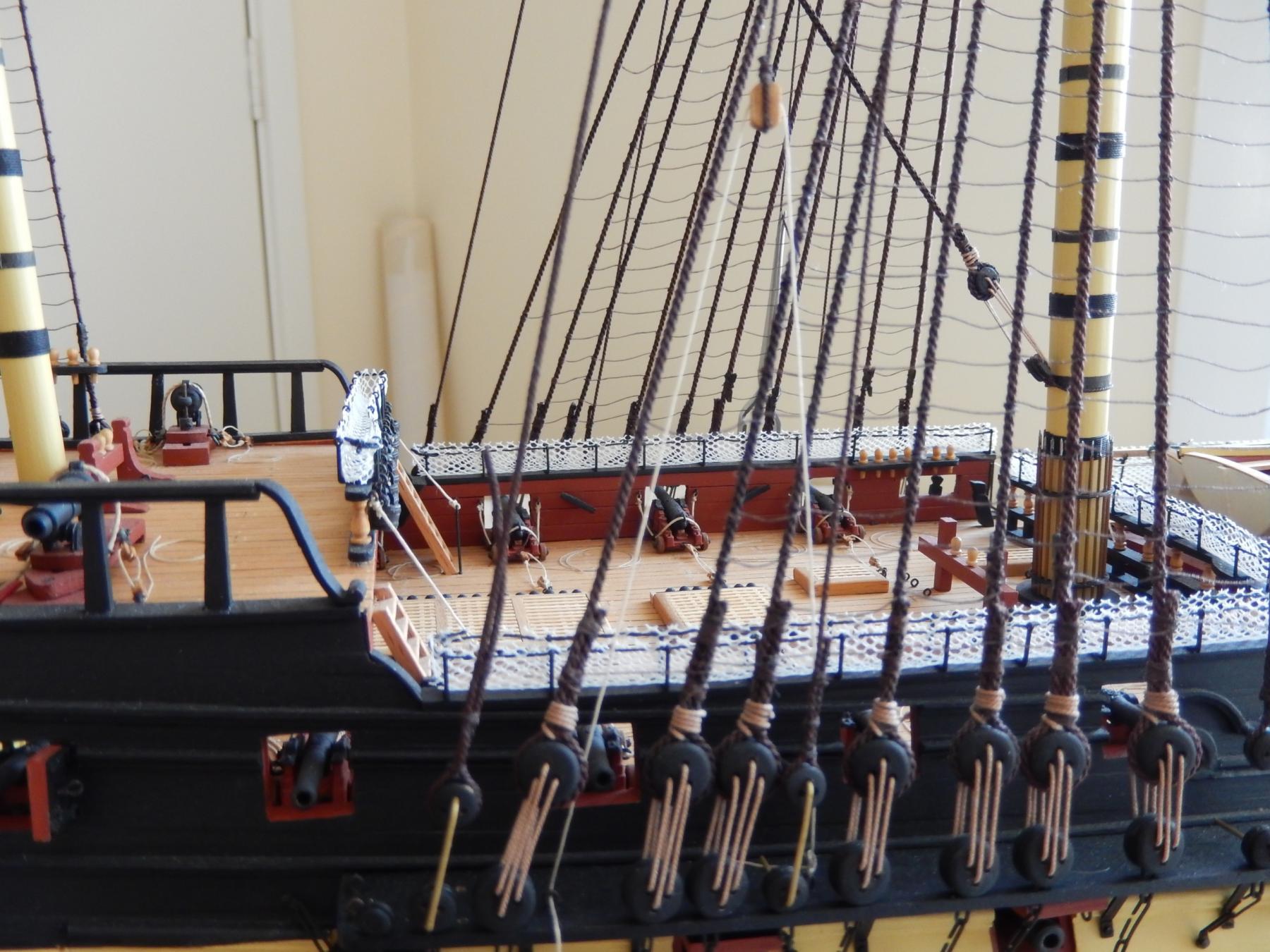
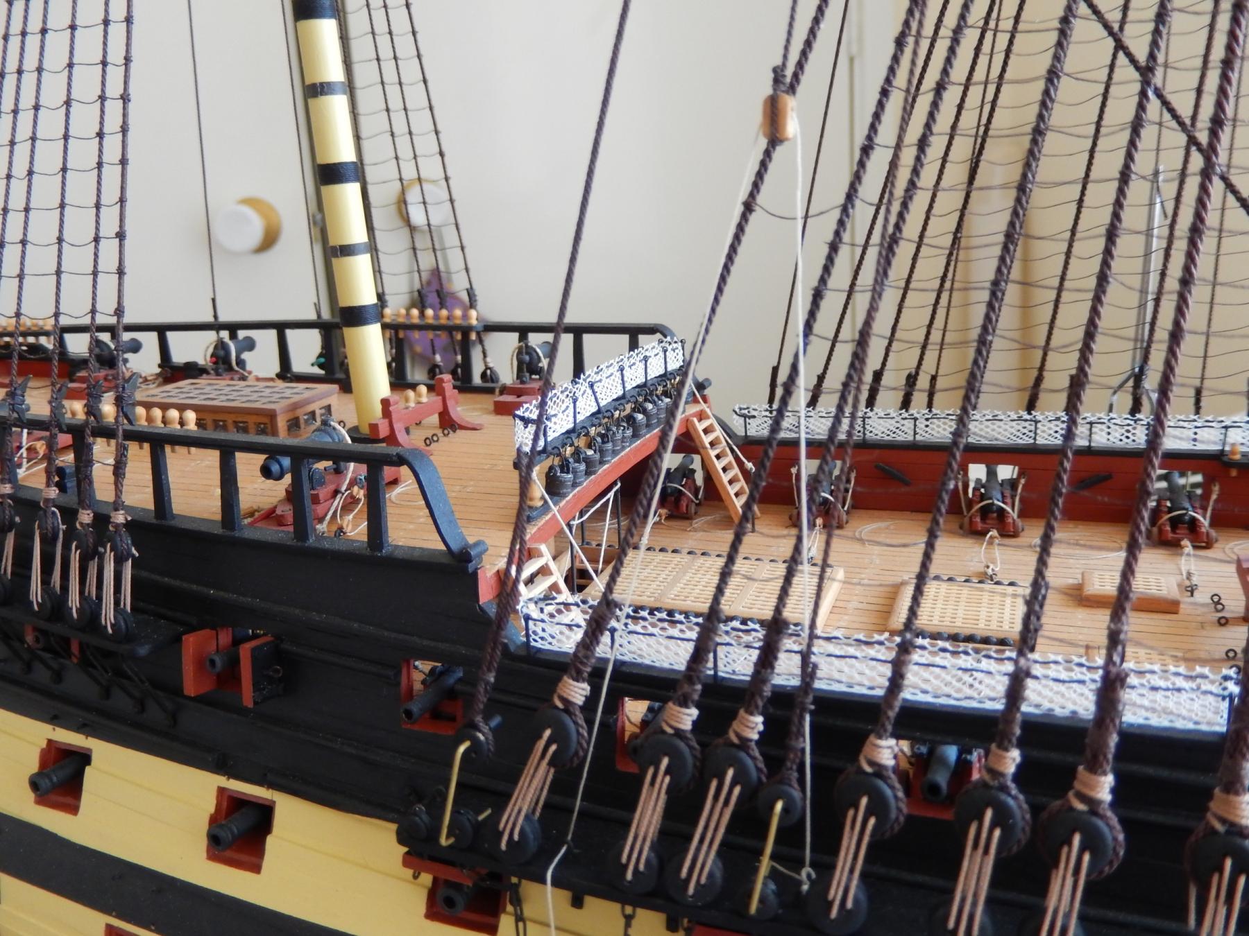
Those following Arthur's log will have seen his main bitts with his virtuoso addition of seven belaying pins. Given the spacing of my existing two pins, I was only able to squeeze another three on. (Actually I doubt if I could have squeezed seven on in any event.) I will rely on my 'less is more' defense in coming up two short. They haven't yet been glued in, and I now see from the photos that some minor adjustments are needed.


- leginseel, russ, mort stoll and 4 others
-
7
-
I haven't had this problem. If I click on one of the photos in the post I sometimes get the white box and the wheel, but it quickly opens the photo. Sometimes the click goes directly to the photo without the box and the wheel. I use XP Pro, which I know these days is considered steam-driven, but it does the job. Sorry I can't help.
-
I don't know about knowing what I'm doing Jason: more like stumbling around in the dark. Thanks for the kind comment.
-
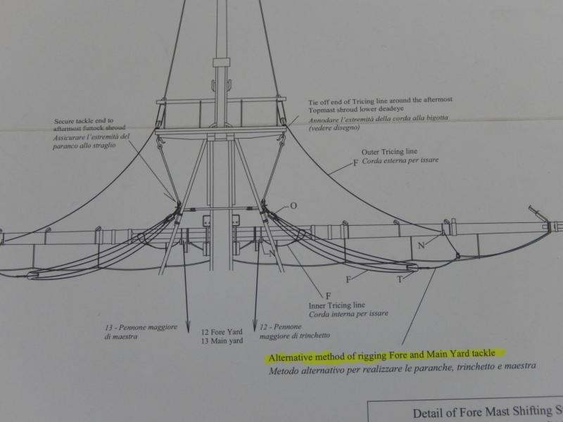
I have come across what I assume to be a minor omission on Plan 1.
An eyelet and hook for the fore yard tackle is shown on plan 9.

There is no such eyelet shown shown on the channel in Plan 1. I have looked very closely at the large photo on the kit box and I cannot see this bit of rigging at all. I suppose I will have to drill holes in the channels to provide for the extra eyelets, but I wonder if anyone else has come across this.
-
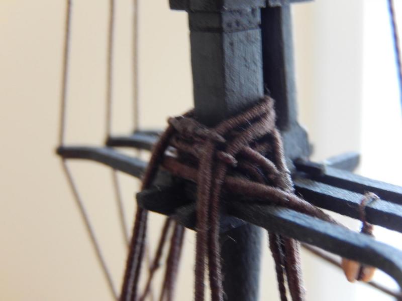
The shifting stays on the starboard side are now complete though again, not finally made off.
Here are the ties for the main shifting stay. This had caused all sorts of confusion as the position shown in the plan is incorrect. Fortunately, Arthur (aew) solved the problem, saving me, and others, time and temper.

and how it looks from the port side. Somehow I seem to have lost the view from the starboard.
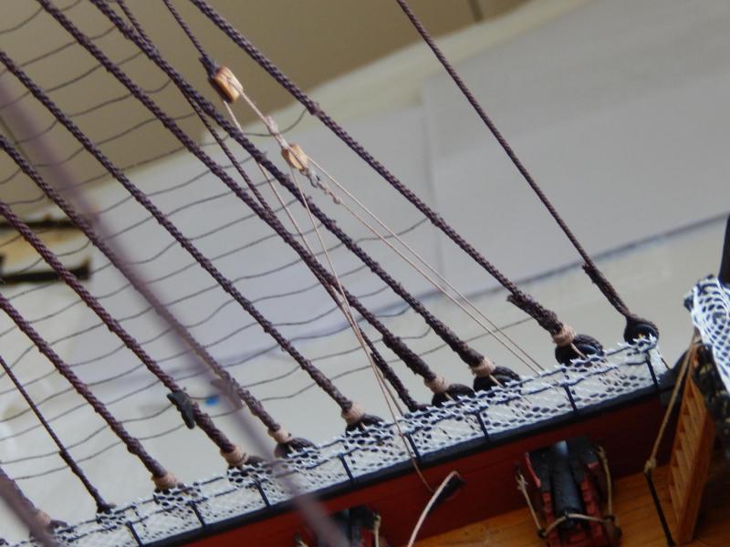
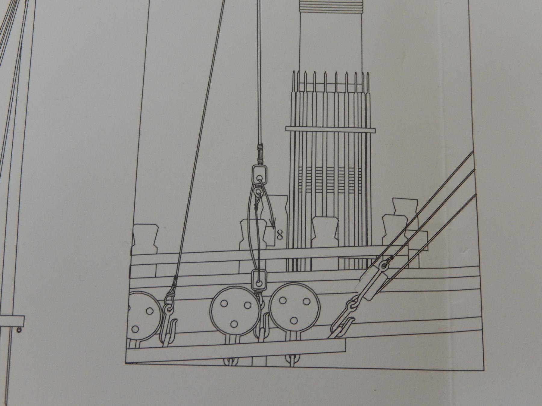
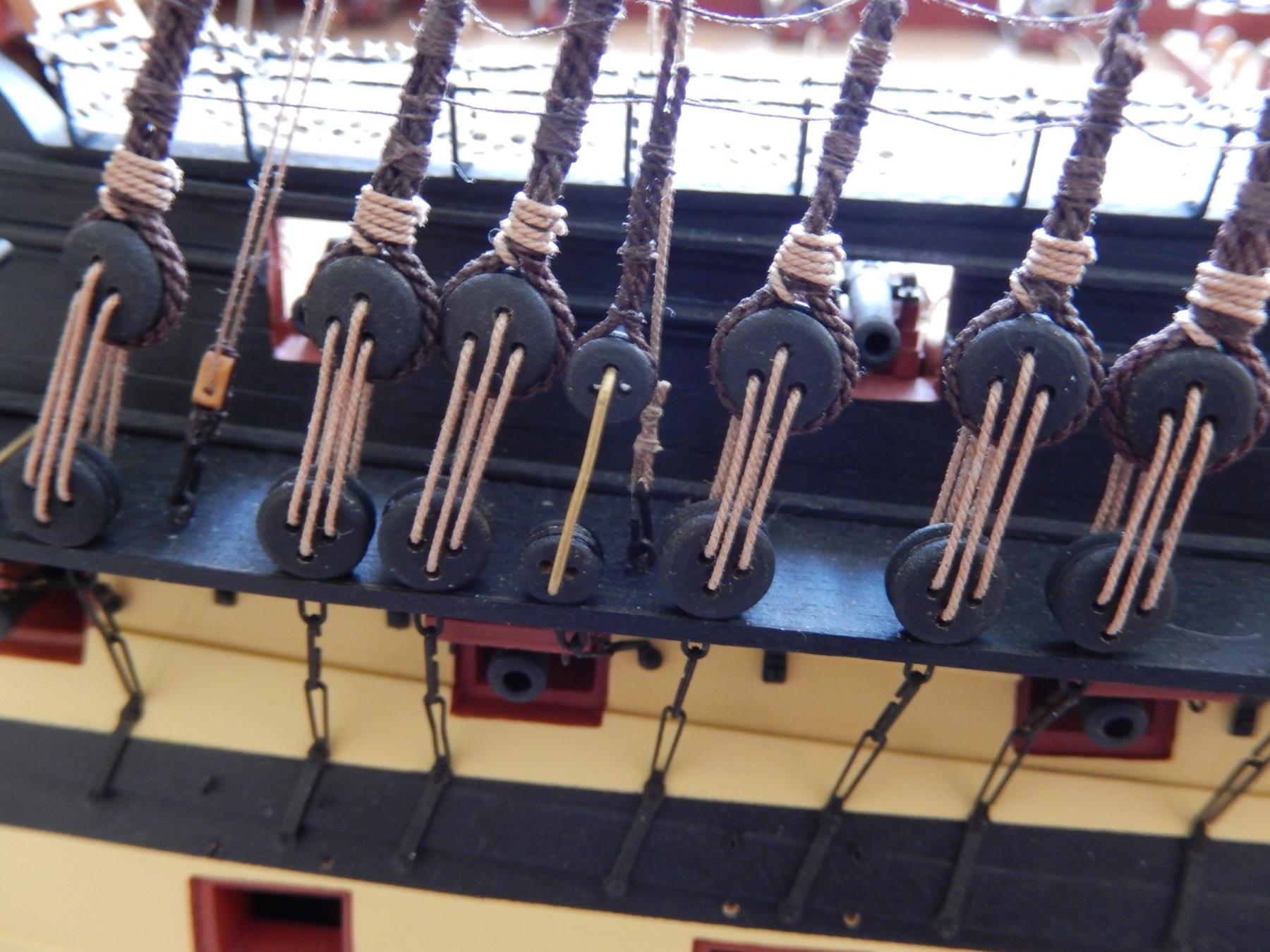
The fore shifting stay caused me quite a bit of trouble. I initially made the mistake of using the spacing between the two blocks suggested by the plan. It infers that the distance between the two blocks on the right side of the picture below are quite close together. This does not work well at all. After lots of trial and even more error, the spacing shown seems to be as good as can be expected. Even so, some of the lashing (?) between the blocks just fouls the ratlines. I then looked at the large photo on the kit's box and there the fouling was far worse, which of course made me feel far better - as such things so often do.
Suggestion: do not permanently fit the hook on the left side shown below. Make allowance for adjusting the length of the thread tied to it. Only fix it once you have the best spacing to avoid as best you can, fouling the remaining rigging on the ratlines.
-
Jose: Thank you for taking the trouble. I have to admit that my instruction book is right at the bottom of the pile. It never occurred to me to look.
I will obviously have to lift my game in future - as a first step I'll try to find the instructions. 
-
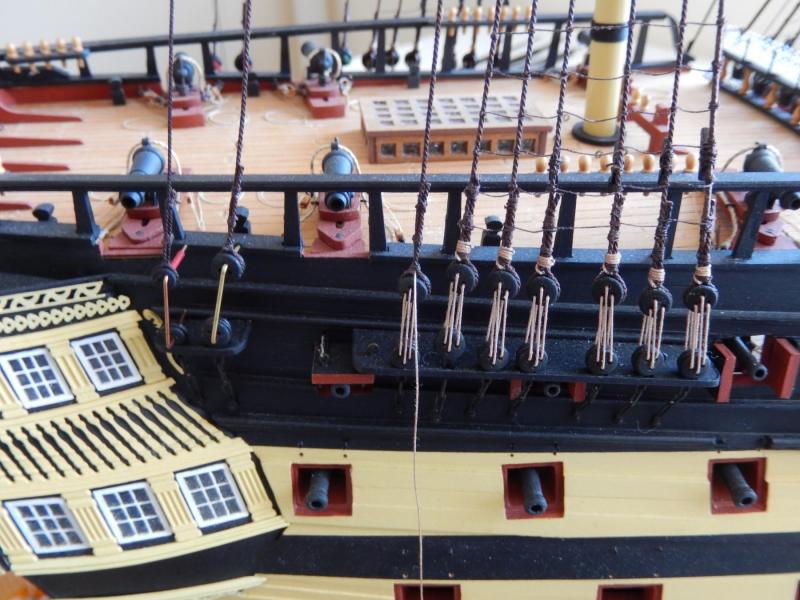
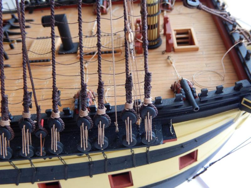
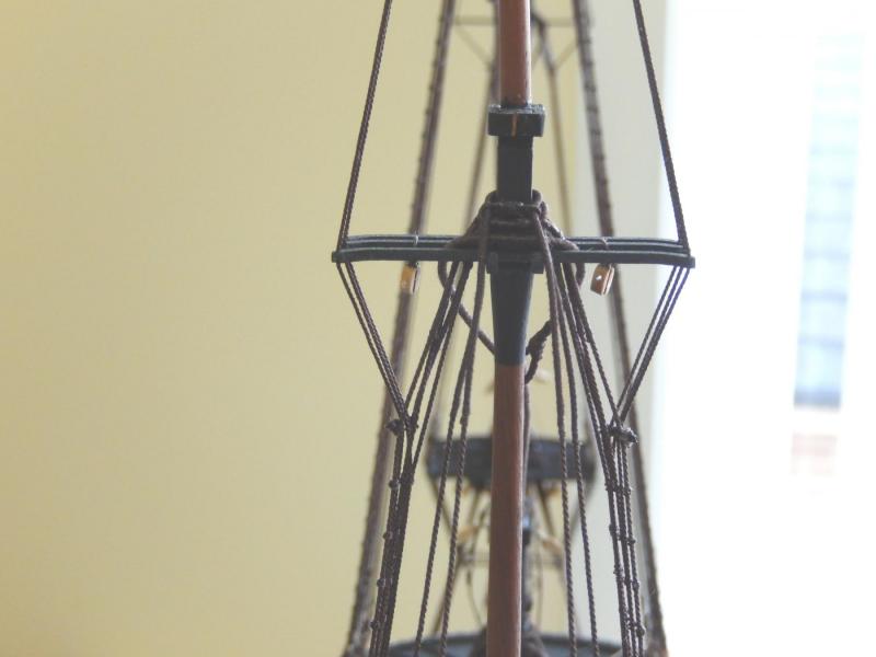
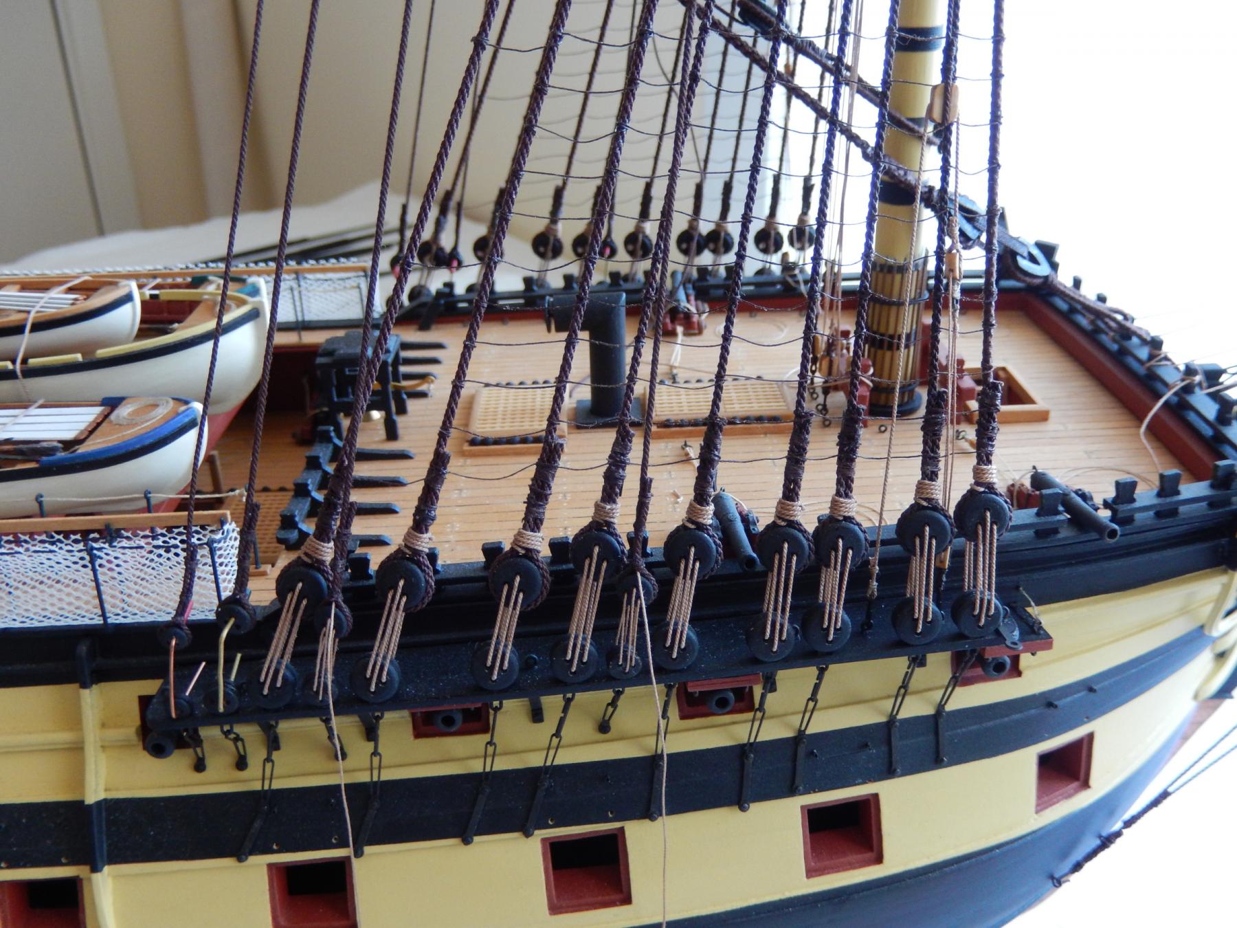
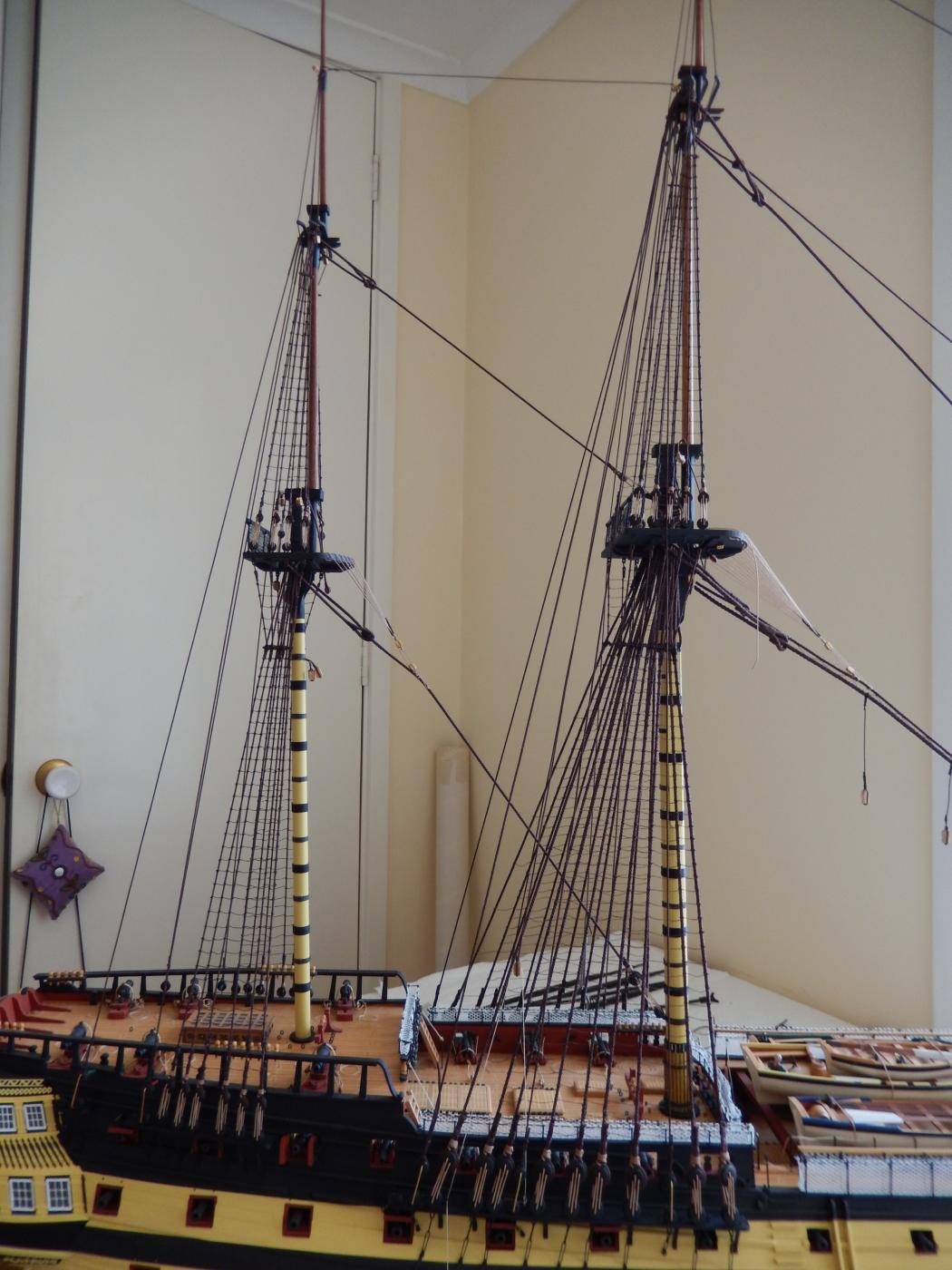
The back stays for the fore mast are now finished, though not finally made off.

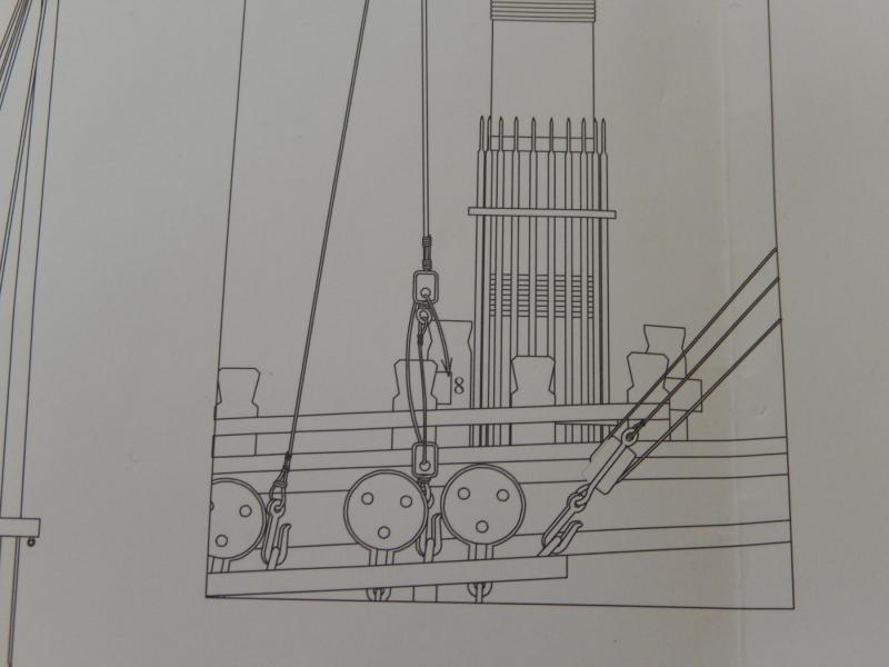
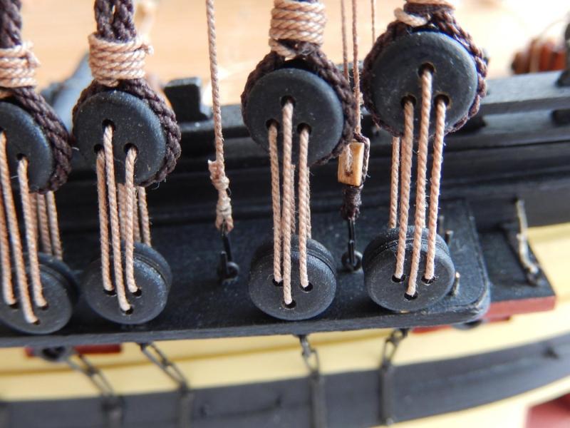
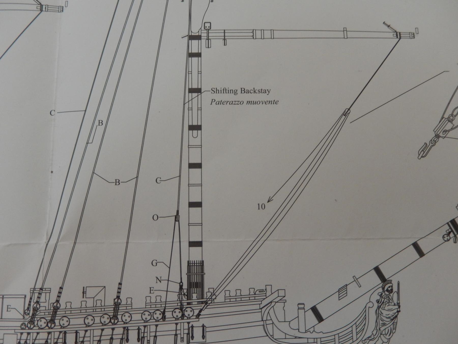
The following photo highlights the problem with the sheaves. The shifting back stay is yet to come (though it is thinner thread than the others). Keeping all the rigging below the sheaves with the spacing shown on the plans is a real problem, though my serving all of the stays probably caused it.
At least I'm fairly confident that I can squash all the rigging down a little to able passing a line through the bottom sheave if necessary.
-
I'm certainly not one of the 'not many'. I'll have to go and actually look (where?), though my record for following instructions is not all that good. It will have to wait until tomorrow though. Having helped my son lay a rather large bunch of concrete pavers today, ship-building can wait.
-
-
-
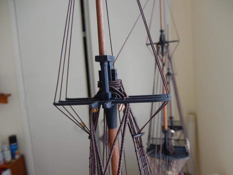
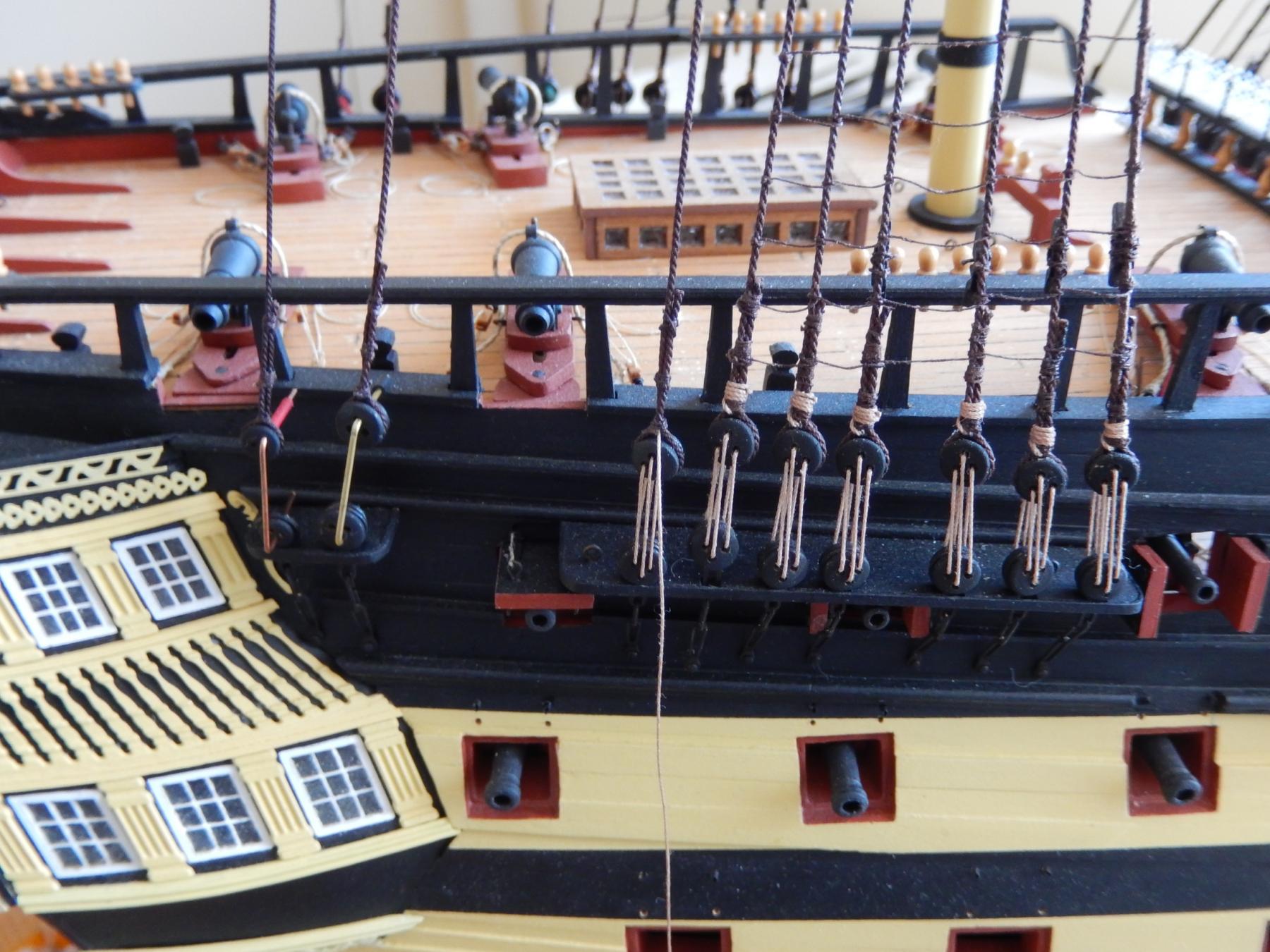
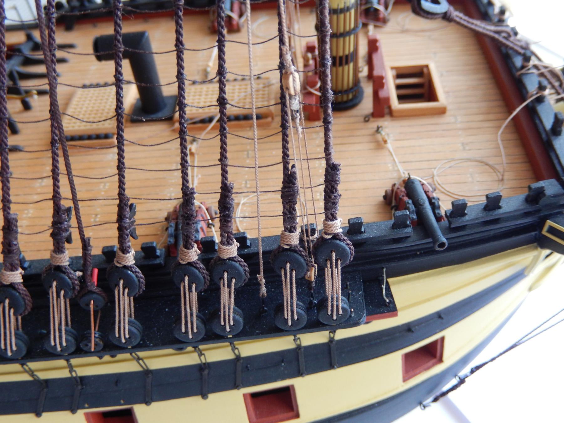
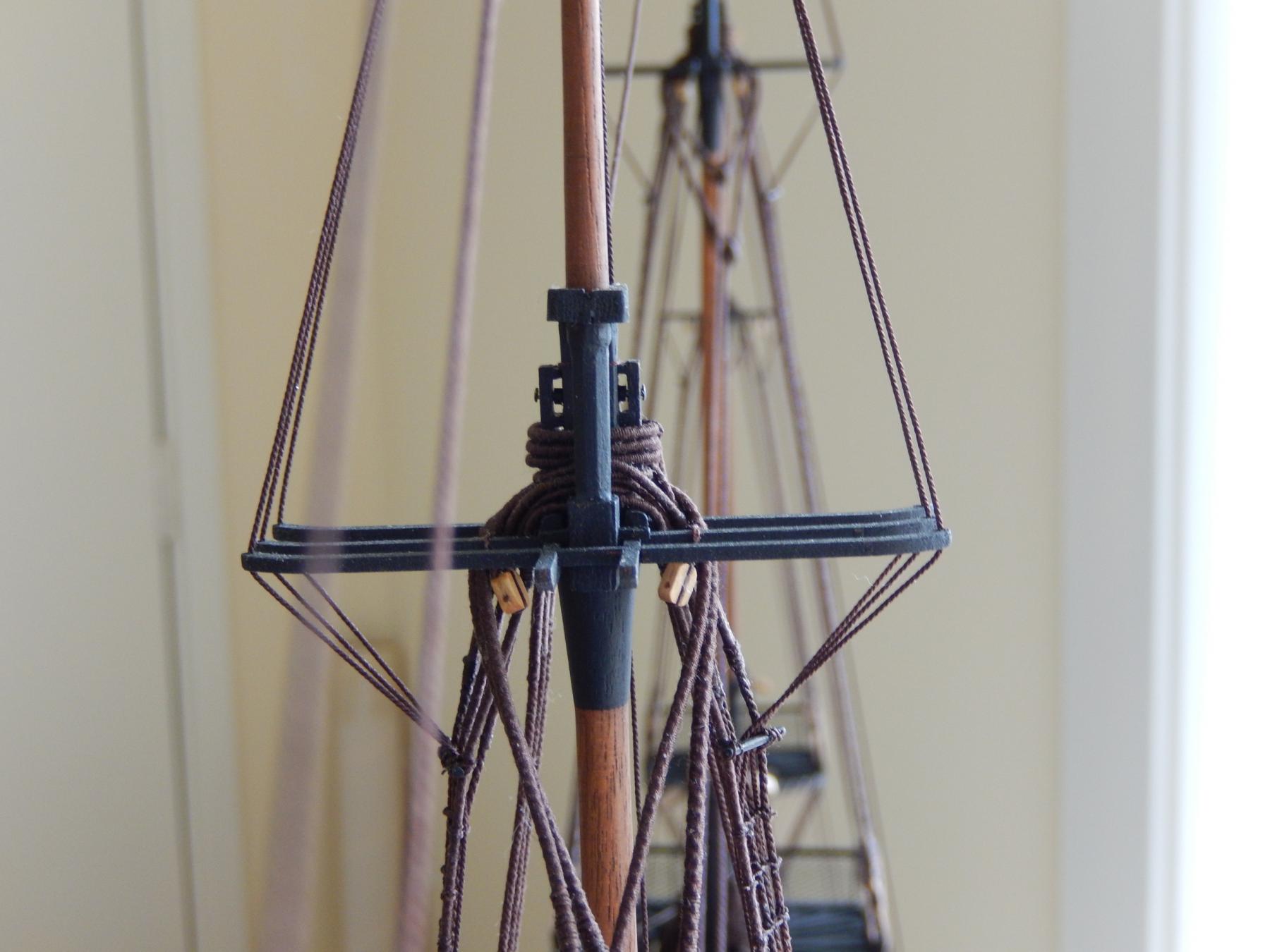
With hindsight I would have mounted the various stays in quite a different order. In putting the backstays on after the forward stays - aside from being incorrect - it made the job needlessly difficult.
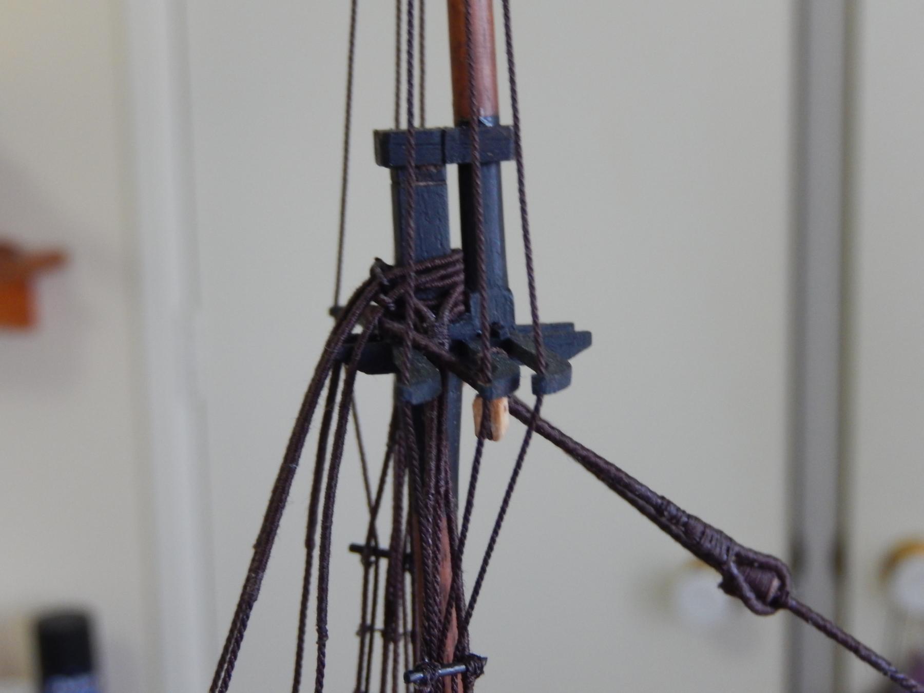
Here are the mizzen crosstrees. Putting the backstays on here was straightforward though the whole thing looks rather crowded.

None of the backstays will be finally made off until as late as possible. This to provide better access should it later be needed.
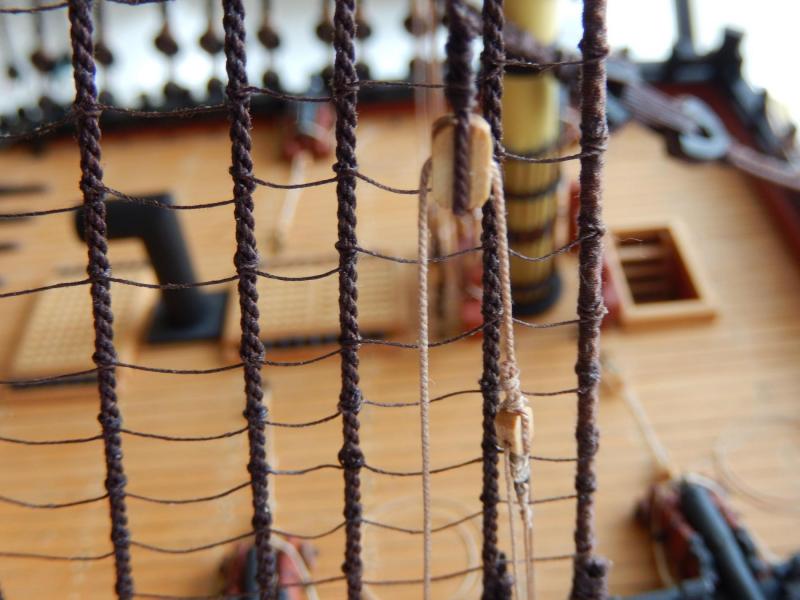
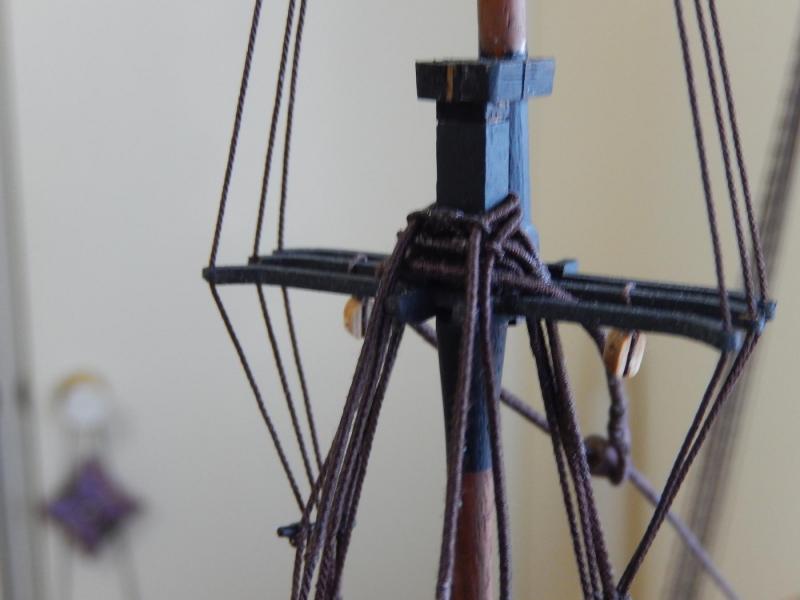
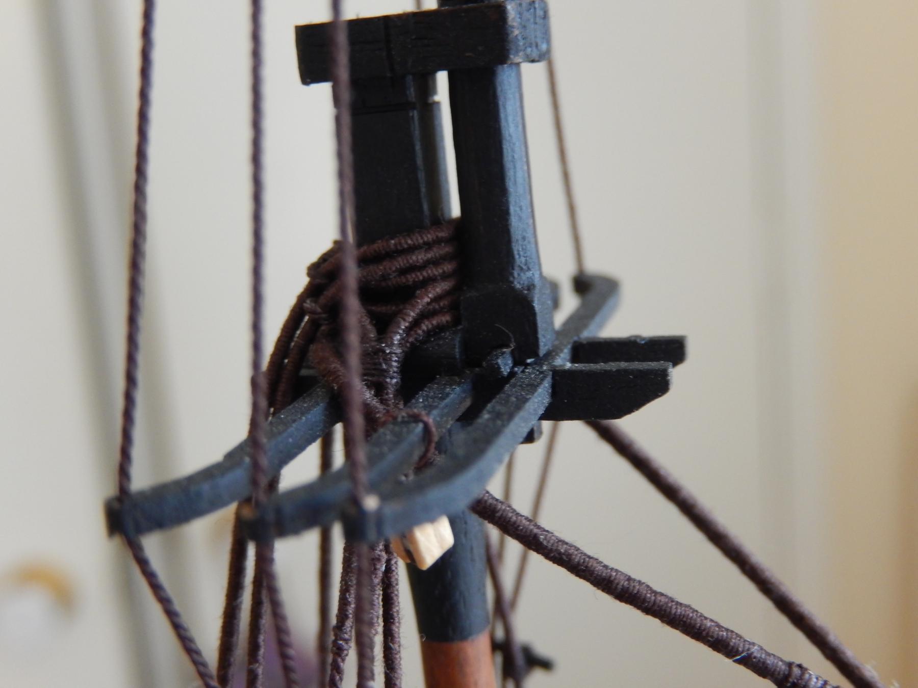
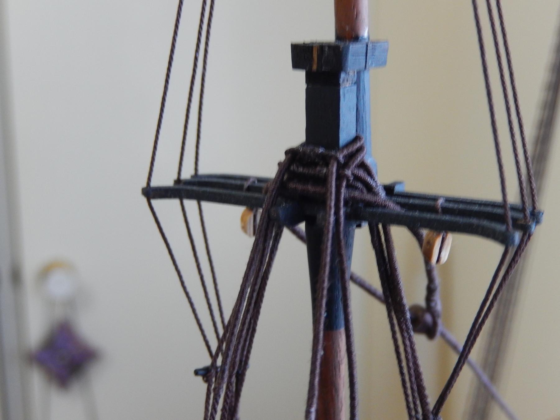
This is where things get interesting: the main crosstrees, below. The stays must be mounted in a way that does not foul the line which leads to the main top through the block shown in the photo. This is really not for the faint-hearted and clumsy of whom I am one.
The other difficulty is the positioning of the sheaves. For those who are yet to get to this stage - put the sheaves up 2 to 3 mm higher than shown in the plan. I will just be able to run a line through the bottom sheave with a little fudging, but it's not really satisfactory. The backstays for the fore mast will provide the same problems.
Another issue is the position of shifting stays. As Arthur has pointed out, the plans are inconsistent, and fortunately I have been able to take advantage again of his experience. Here, I have simply run a piece of thread through the block on the end of the stay to see how it looks. Surprisingly, it seems to avoid fouling the other rigging, though whether that remains true when properly rigged remains to be seen. The whole thing does seem to be a rather odd bit of rigging.

and here is progress
- mort stoll, kier, AON and 3 others
-
6
-
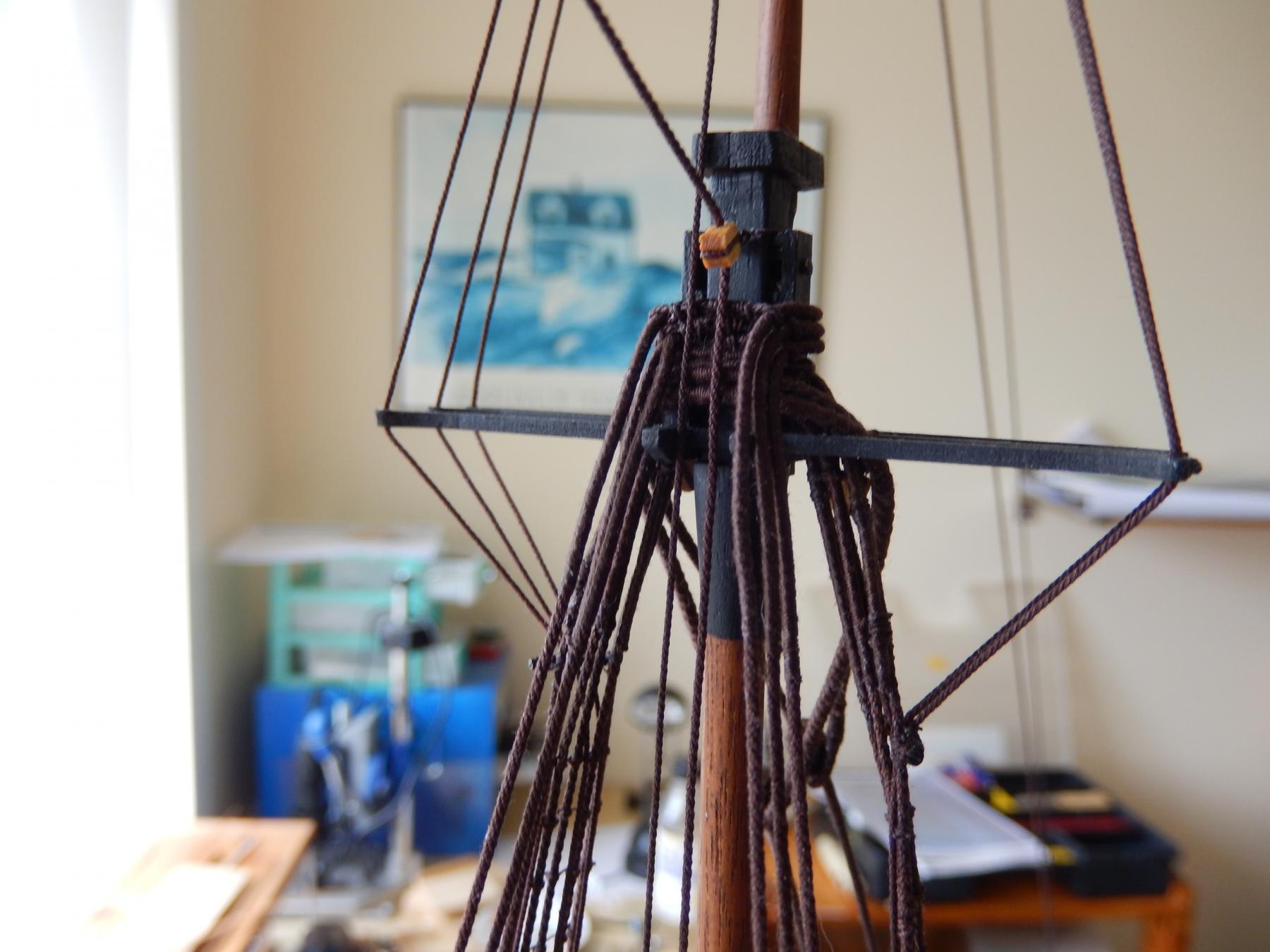
I have redone the loops and this time have not placed them around the top gallant. I tried threading the backstay inside the loop of the stay. I addition to being a slightly hair-raising process, it had some unintended consequences: it altered the tension on most of the forward stays. Rather than redo them all, I decided to simply put the backstays on top. It doesn't really show and only Arthur and I will know, and I at least won't tell. The two back stays on this mast can be fitted between the aft two ribs of the cross trees, but not with the rigging in place on the fore and main. I'll go with consistency.
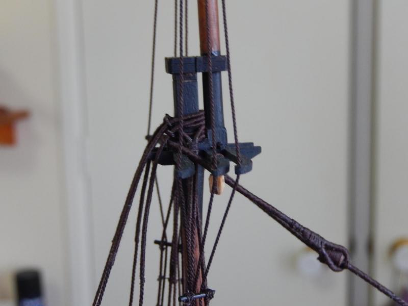
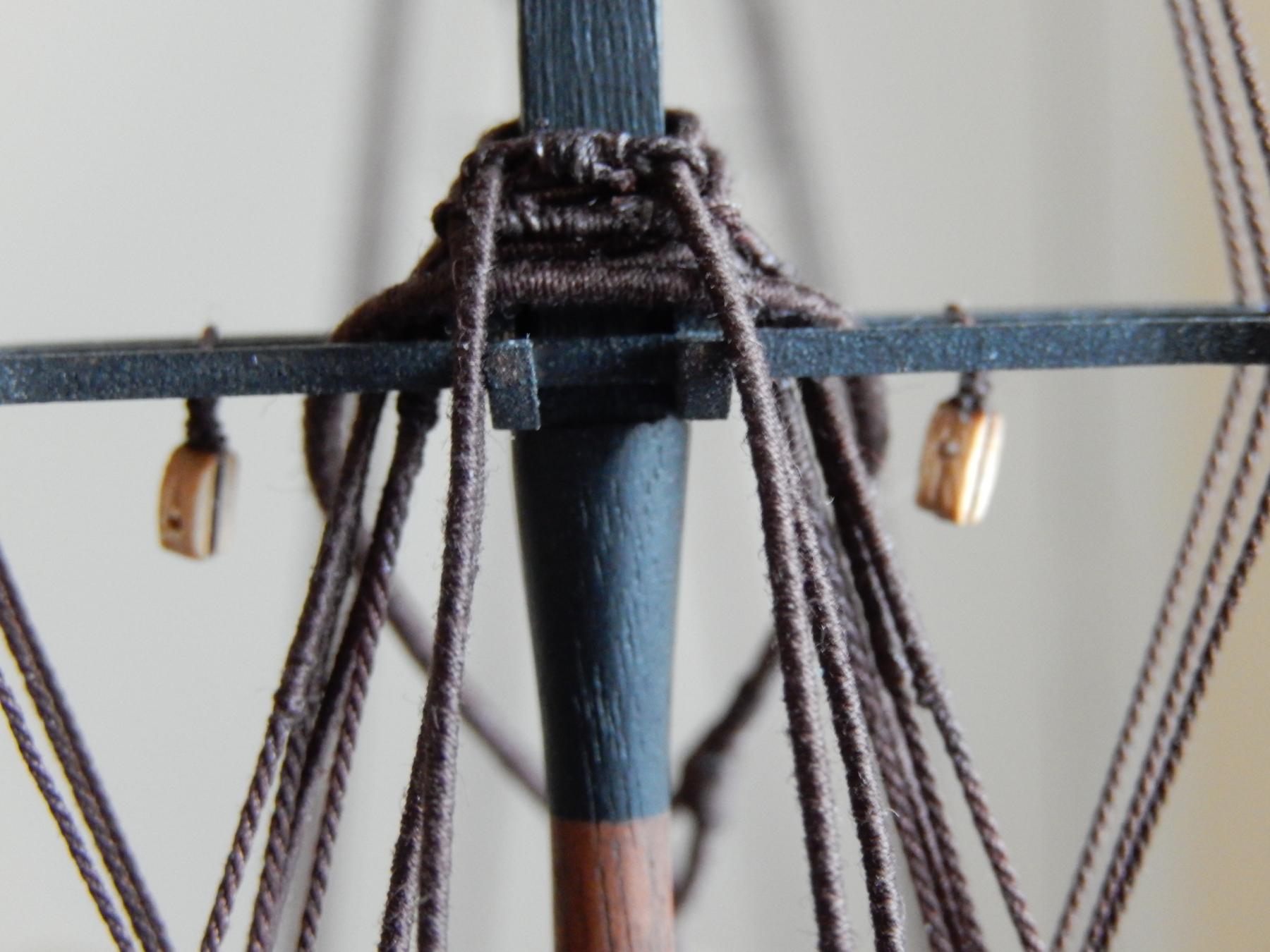
The next photo shows up every tiny fault. I should stop taking close-ups. In fact the whole thing looks quite good on the model, though I will clean it up a bit - and I still haven't touched up the cap and mast. Neither of the backstays here are tied off yet.

- dgbot, mort stoll, russ and 2 others
-
5


HMS Vanguard by RMC - FINISHED - Amati/Victory Models - scale 1:72
in - Kit build logs for subjects built from 1751 - 1800
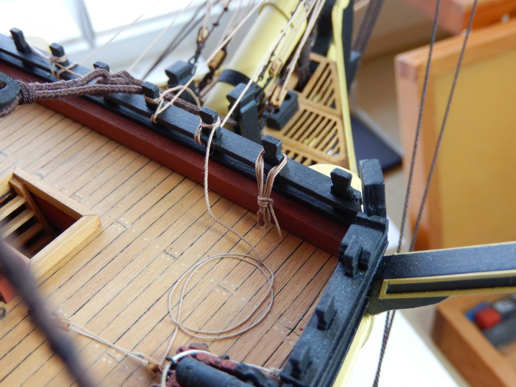
Posted
Hi Jose. Sorry for delay in replying. We've been away for a few days. The photo shows how it was done on the Astrolabe. It seems to be pretty much the same as Arthur's Gulnara.