HOLIDAY DONATION DRIVE - SUPPORT MSW - DO YOUR PART TO KEEP THIS GREAT FORUM GOING!
×


robdurant
-
Posts
842 -
Joined
-
Last visited
Content Type
Profiles
Forums
Gallery
Events
Everything posted by robdurant
-
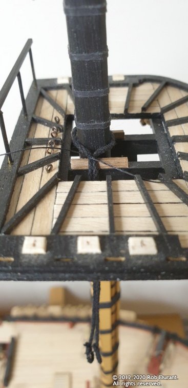
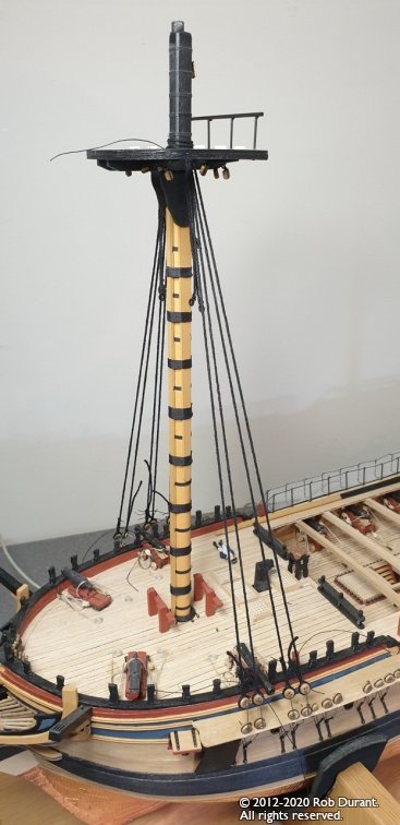
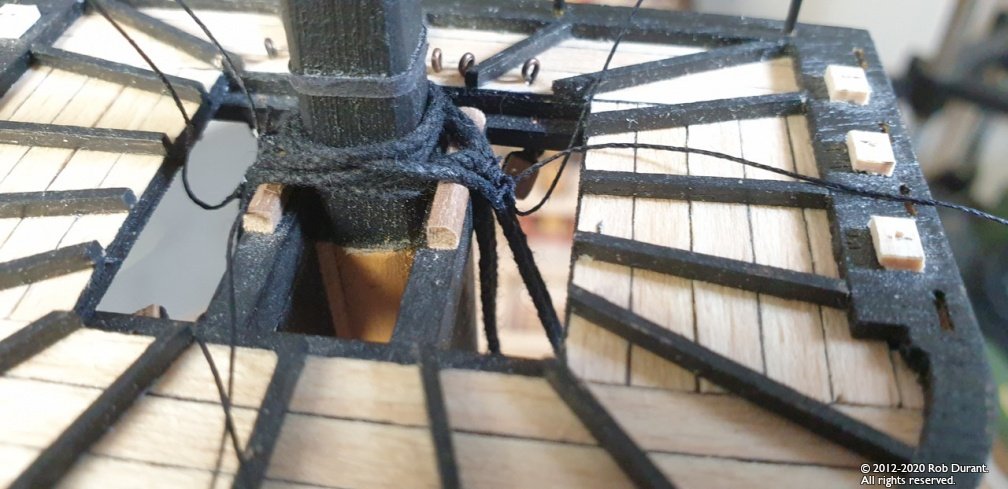
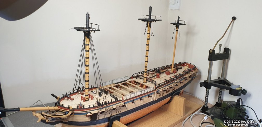
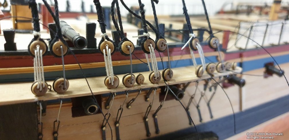
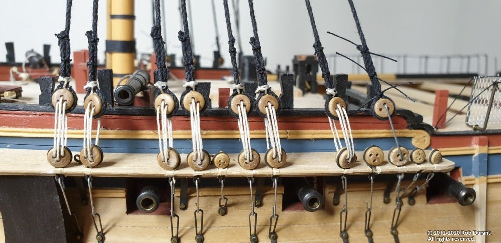
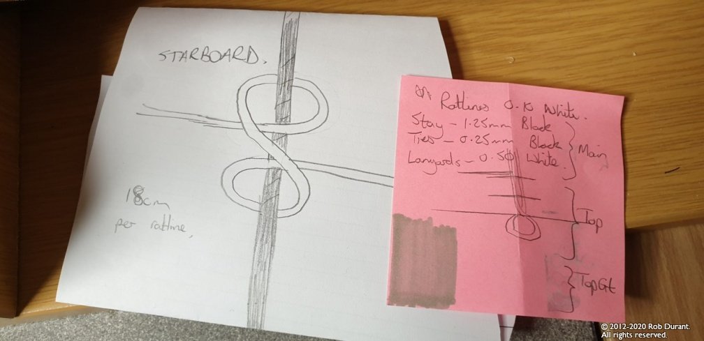
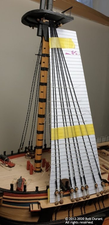
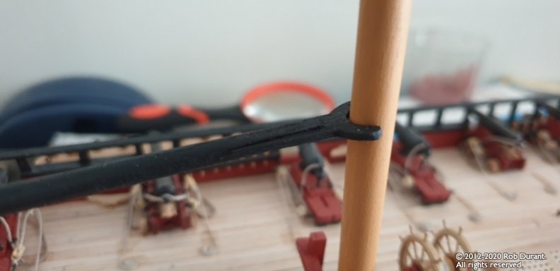
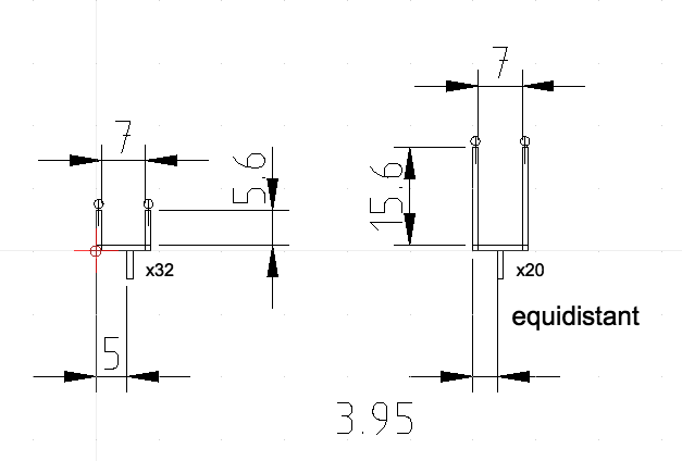
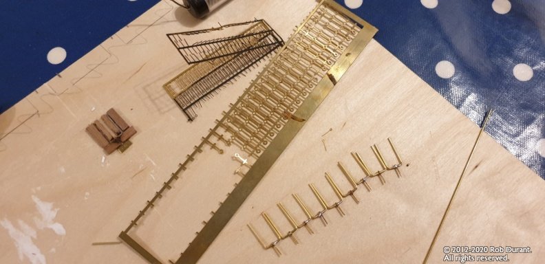
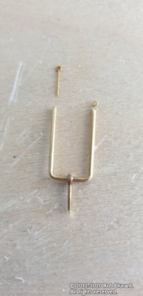
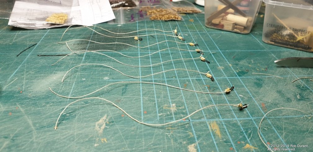
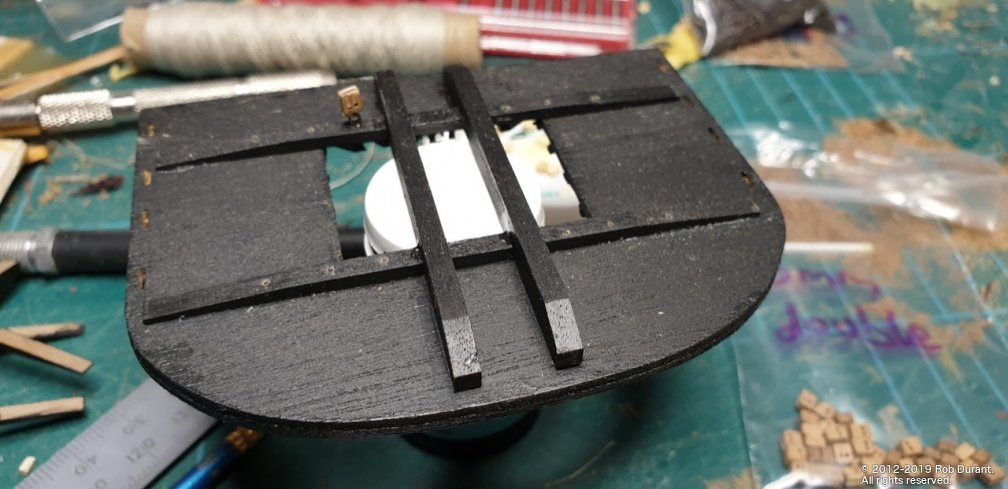
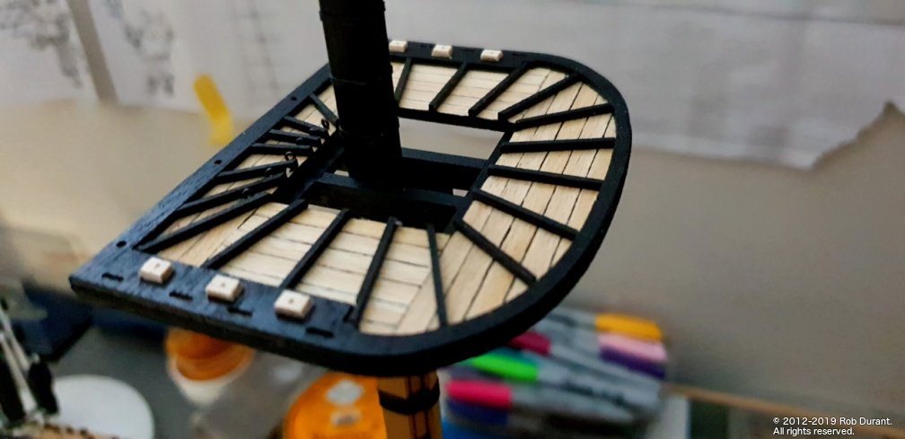
 Hi all, It's a few weeks since I last posted, and lots has happened in the shipyard. Fighting tops I wanted to finish off the fighting tops, so I could get shrouds in place, and start the (significant) job of the ratlines. That meant constructing the barrier at the back of the fighting tops. I was concerned that wood would be a little vulnerable in that position as I rigged the ship. Also, I suspected that the ship itself had metal posts, and not wooden uprights, so I ordered the smallest square brass cross-section I could fine, and set about soldering them with a little jig made using balsa and pins. Burton pendants These are added to the mast before the shrouds - made of 1.25mm thread, tied with .25mm thread and secured with watered down Aliphatic glue (carpenters PVA). My understanding is that they're attachments to which temporary rigging can be fixed when necessary. Starboard first, Larboard second for the main and fore, one hanging down on either side on the mizzen mast. That was achieved by unravelling the rope in the centre by twisting it - passing it round the mast, and then letting it spring back. Shrouds Again, a starboard pair, then a larboard pair - starting at the front and working back. I used 1.25mm black rope for these. (The recommended 1mm looked a bit weedy to me!) It's worth noting at this point that if the shrouds don't sit on top of each other, but sit side by side (i.e. the higher loops are bigger and sit down around the lower) - you may run out of space between main and top masts, and it will force the base of the topmast forward, thereby stopping the two from being parallel. Thankfully, when I checked this hadn't proven an issue, but it almost caught me out, so hopefully others will avoid the dilemma. Bent steel wire was used for spacers on the deadeyes whilst rigging the shrouds... I found the recommended brass wire both too large in diameter for the deadeyes, and suspected the wire I had might be too soft. As you can see below, I rigged the lanyards on one side of each shroud pair first, before I secured the other end of the shroud so that I could be confident of the length. As it was, I think I still left the shrouds a little loose, but I didn't want to pull the chainwale off the side of the hull causing all sorts of inglorious muttering and holding of head in hands. As running rigging, the lanyards were 0.5mm light rope, and I'm quite pleased with the contrast... Rattling down the ratlines I wanted to learn serving, and rope-making, but those are going to have to wait for the next model DISCLAIMER: Now comes the controversial bit. Bear with me here. I've used both light and dark rope in the past for ratlines. I like the light. It's a personal choice. I know it's showy. And this is a showy frigate... just look at the paintwork - the captain would rightly have been proud of this crack frigate... so I've gone with untarred manila! I know it's probably not the right colour, but hey... it's my model And I really like the effect it made on my Pickle schooner... Sherborne and Royal Yacht Caroline both look great with black ratlines, but I also found the 0.1mm thread much easier to get neat scale tidy ratlines with... So. That's the decision. I'm 1200 knots in, so the decision is well and truly made... and I'm not about to go anywhere near this model with india ink (as the instructions suggest) - I'm simply not brave / foolish enough to attempt it over neat maple decks. With that said, I printed off a bunch of CAD sheets with lines 5.8mm apart, and used these as the guides. Here are the pictures of progress so far. It always takes me a bit of head-scratching to remind myself what a clove hitch looks like... (at least the way I do them - am I wrong again?) And an inspection of the work so far... I find by applying watered down PVA to each row as I finish it, the whole thing stiffens up quite well, and as I go it gets quicker... This way I can pull out the tension as it shrinks, too and avoid the whole thing bowing in and becoming curved along its length. (to some extent at least...)
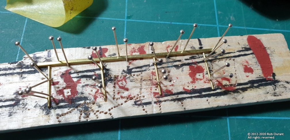
- 275 replies
-
- 11
-

-
Not sure if it's helpful, (and apologies if this is over-technical - I've tried to keep it simple) but speaking as an internet programmer, it might help to understand a few of the nuts and bolts? JPEG images (the ".jpg" format we tend to use) are saved by most cameras (and phones) with data embedded in the file called EXIF data... it contains all the information like the camera model, the image size, the colour profile of the photo, and also it CAN contain information on whether the image is rotated... it's a quick and easy way for the phone or camera to say - I've stored this landscape, but actually the camera was vertical, so it's 90 degrees to that... without having to actually move the pixels round (a much more intensive task for a computer) 1. Depending on what you use to view the file, that exif data may or may not be respected... It usually will be on your home computer using the picture viewer... It may not be by your web browser... and the results will vary between windows / mac and different browsers... it isn't that the website server is getting things wrong - it's just how it looks on your computer. 2. When you modify the image - e.g. resize / re-save - depending on which application you use to do that (i.e. iPhone gallery / Windows Photo / Photoshop etc... / online resizer ) that EXIF data may or may not be included. Clearly if it is not included, then when that image is displayed the computer / phone displaying it has no way of knowing that originally it was intended to be rotated... Basically - if you want it to show the right way round, then don't trust EXIF - you need to force the computer / phone to actually rotate the image data (perhaps using GIMP/ Photoshop or equivalent), not just put a note in the EXIF data. That's the only 100% fool proof method. With that said, I've just updated the script I use to resize my photos to include the EXIF data when it resizes them (it wasn't before) and now the portrait images taken on my phone (which are stored landscape with 90 degree EXIF rotation) show up correctly. Anyway - hopefully that gives some insight into the complexities of simply getting an image the right way round on a webpage. And finally - thank you to all you wonderful people who do such a great job of maintaining this forum! You make a complex task look very simple, and I'm sure that takes a lot of behind the scenes effort. Much appreciated. Rob
-
One question - are each of the planking strakes straight, or did you curve them to fit the hull? It sounds from your description like you made them straight, then used plenty of pva to make them pliable enough to side-bend when fitted?
-
Wow - that's how my first attempt was going to turn out in my head, and mine ended up in the scrap heap... Beautiful work Jason. You have every reason to be pleased. Having just attempted to build this mini-kit, I have some idea of quite how fiddly it is.
-
Hi Eamonn Thank you for your kind words. There's something very pleasing about working out the lines for yourself - and on the scale of a ship's boat, it's manageable - I'm in awe of those who try to draft entire ships themselves. That's another level! Thanks Jason It's going to be immensely over-engineered, but that's the joy of this hobby... I can choose to spend more time than is rational, simply because I want to I hadn't quite appreciated how small it was on the screen, but when I printed it out and began to cut it out, the challenge became apparent pretty quickly! Thankfully the parts are quick to shape because they're so small. Any mistakes, and one can simply make the part again. I taught myself 2D CAD using QCAD Pro, because I got frustrated with trying to get other applications such as Word to print things out at the right scale, and it's proved useful time and again as I've worked through this build. Rob
-
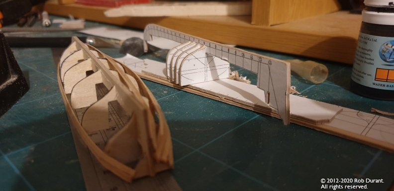
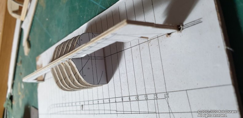
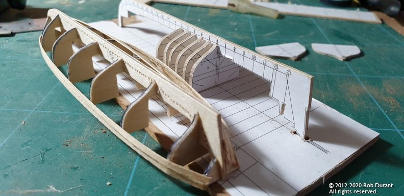
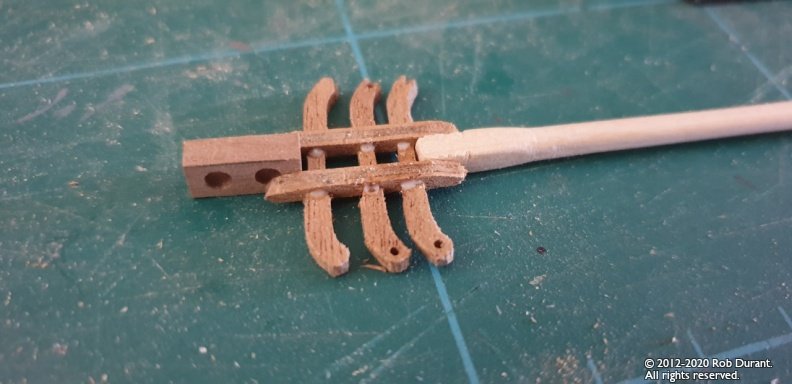
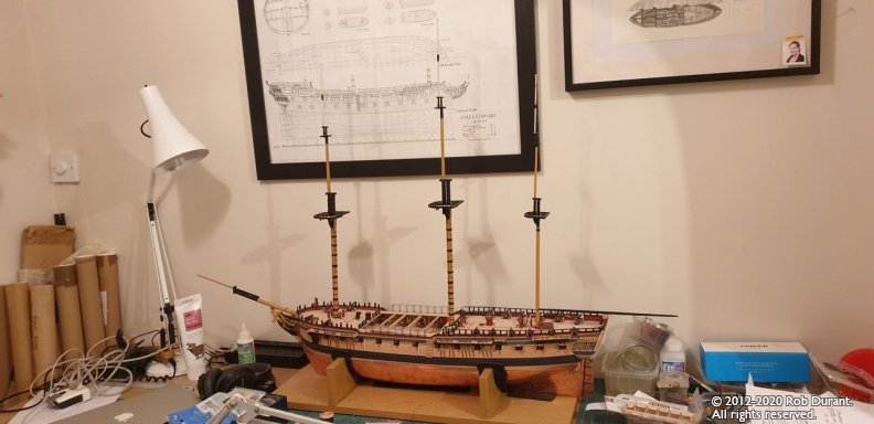
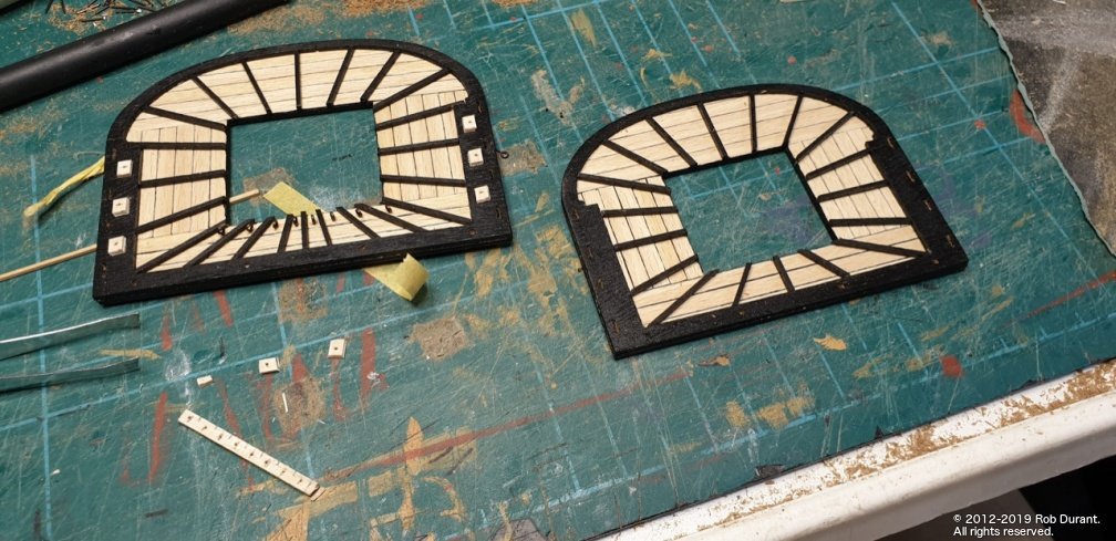
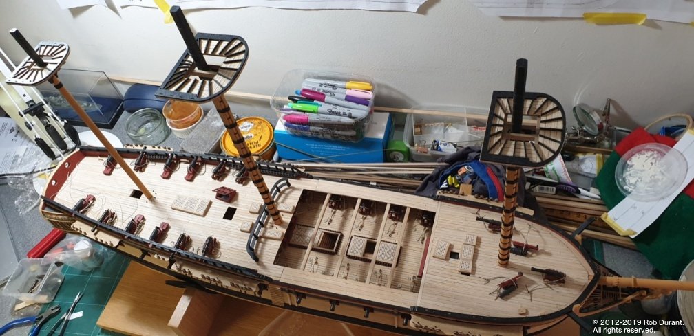
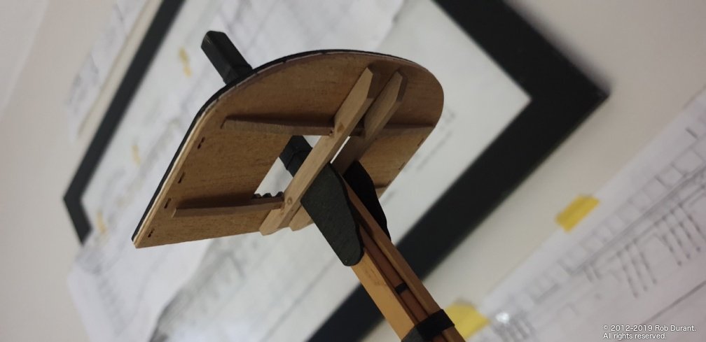
Time for another update, although progress has been limited. I've done a little to the pinnace, drafting, cutting out and making a build board for the skeleton of the boat. I'm hoping to make the keel a snug fit but not glue it, and then once the hull's planked, I shall try and lift keel and shell off the former... then I can add scale frames, and details. That's the plan. Time will tell whether it works. I'm beginning to realise that I wrongly assumed that thin planks would make planking the boat easier - in fact, if anything slightly thicker stock may be easier, as it is more forgiving to be sanded down to achieve a neat shape... I'm interested by Jason (Beef Wellington)'s suggestion he may use card to create a clinker effect... the thought had crossed my mind (having done a little work on a Shipyard Models HMS Mercury)... perhaps natural wood on the inside, and card on the outside? We'll see. Some of these photos have the caldercraft supplied frame alongside to show the difference. In addition, I've finally finished the cross trees for the top mast / topgallant mast junction. These were small and fiddly, and the wood wasn't the best, but I'm pleased enough with the outcome. This photo is of the smallest - the mizzen cross tree - note the lack of holes on the foremost cross member. I'm using the topgallant mast as a spacer to make sure the mast fits once it's all glued. These are now painted, and the ship has reached her full height. (All dry-fitted - hence the slightly odd angles - until the rigging is well under way - indeed, much of this will remain dry-fitted once complete, as the rigging holds it all nicely in place.
-
How interesting. Thank you. Yes it would be fascinating to understand the journey from one usage to the other.
-
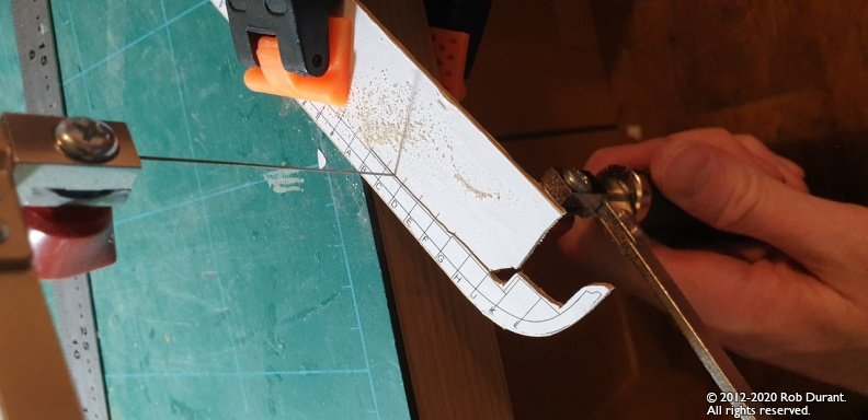
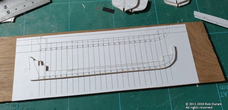
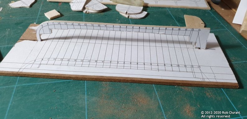
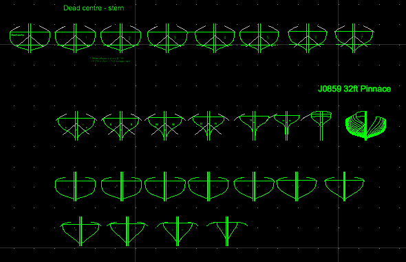
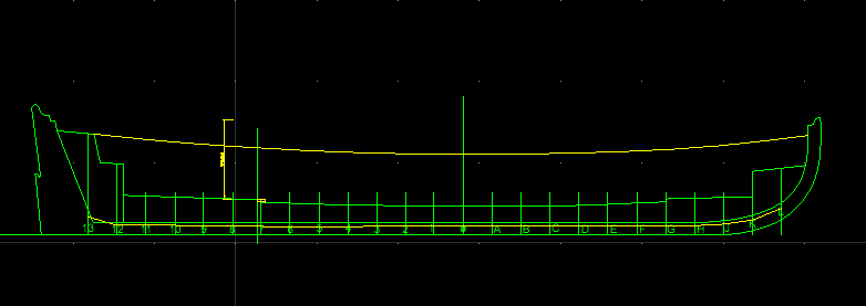
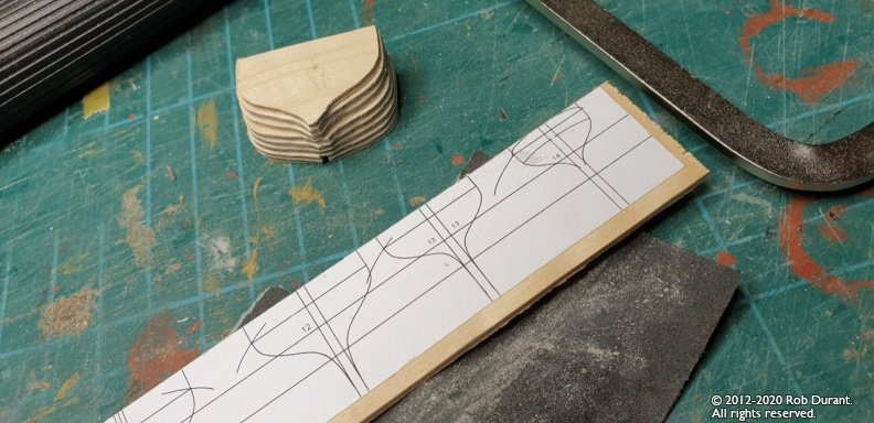
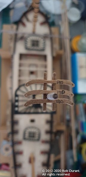
Thanks Jason I've been pondering the ship's boats... (My backup plan is to buy the caldercraft resin boats - which are okay, but a bit pointy at the bow, and I'd rather conquer the challenge myself) The kit bulkheads have caused me no end of trouble so far. I couldn't get the curves at either bow or stern, and if I wanted to make the center removable I couldn't get the planks to stay together. It's weird, because I managed the ship's boat on Royal Yacht Caroline - for some reason this is just fighting harder. Anyway - I decided to go back to basics. I had a look on the RMG website for 32 foot pinnaces and found a design from Portsmouth from a few years before Ethalion was launched. J0859, here: https://prints.rmg.co.uk/products/32-ft-pinnace-j0859?_pos=18&_sid=f62fc5df9&_ss=r And I've been creating my own framework to build the boat on... As below: It's a work in progress, but the resulting frame should be much much better for laying those really thin veneers onto, and getting a good curve. So far I've only cut out a few of the bulkheads to test out my theory. The design is printed onto A4 paper, glued (with Pritt-Stick / UHU-stick) onto 1.5mm ply, and then cut out with a piercing saw and finetuned to the line with sand paper and files. It's time-consuming, but quite rewarding really. As you can see, I haven't cut the centre slots yet... they weren't on the design when I did these ones. They are now. I'll add them manually for these bulkheads. As you can also see, the bulkheads all stretch up to a universal line, so that they can be mounted upside down on a board, as I believe Harold Hahn did for his models. As I say the designs are very much in progress, but here are the frames as an A4 PDF if you want to take a look. wip_32ftpinnace_bulkheads.20200517.pdf I expect to build the frame over the bulkheads and then remove the majority of the bulkheads - but time will tell how that really works out. Anyway - that's my thinking so far. Rob
-
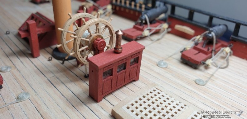
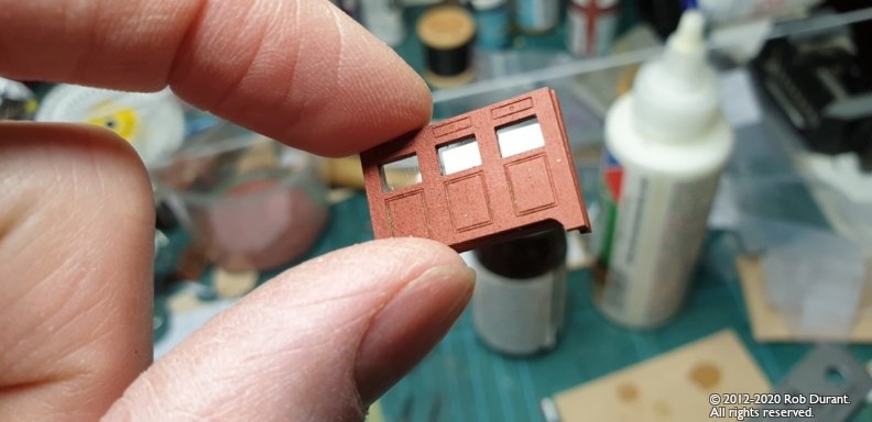
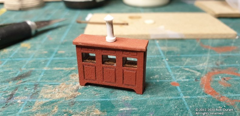
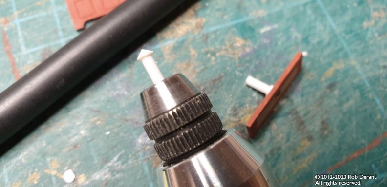
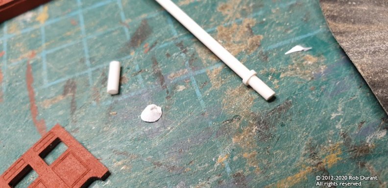
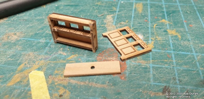
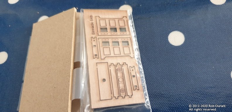
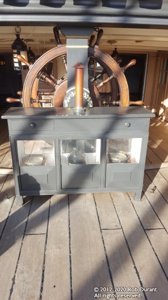
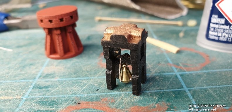
The BInnacle (courtesy of Vanguard Model's excellent mini-kit!) Here's the space it's going into... The kit is a single sheet of laser cut pear, well packed in solid mdf. There are no instructions,but it's a pretty simple shape with plenty of support, so it isn't too fiddly. (13th August 2020: UPDATE - My apologies to Chris. There are instructions, but they're on the website on the page where you can buy these binnacle kits... just click on the image thumbnail, and you'll see very clear instructions on how to assemble this brilliant mini-kit) I decided against putting the compass and lantern inside as it's virtaully impossible to see, but I'm sure others will choose to The next step was to put on a chimney, as per the Victory binnacle below (my photo): The first attempt was with a paper cone at the top... The paper cone was far too fragile, and (for me at least) was just a mess. The second attempt was with plasticard mounted in my mini drill and files... A little ring of styrene tube was added at the bottom. I left off the back side so I could glaze the windows (having painted as much as possible - inside, white, outside, red). And then it was time for final assembly, some light sanding, a final coat of paint and fitting to the model so that the guys at the wheel can steer true! The chimney was painted with black then copper to give the copper a darker toned down sheen. Thanks Chris for an excellent addition - I've been surprised by how much it adds to the quarterdeck when put alongside the upgraded ship's wheel. It really looks the part. Happy building Rob
-
Wow - I ordered from you on Tuesday, and lo and behold, the binnacle's here already. I look forward to assembling it forthwith. It's the first sight I've had of the work you're now doing with your laser cutter, and it looks exceptional! Thank you Chris.
-
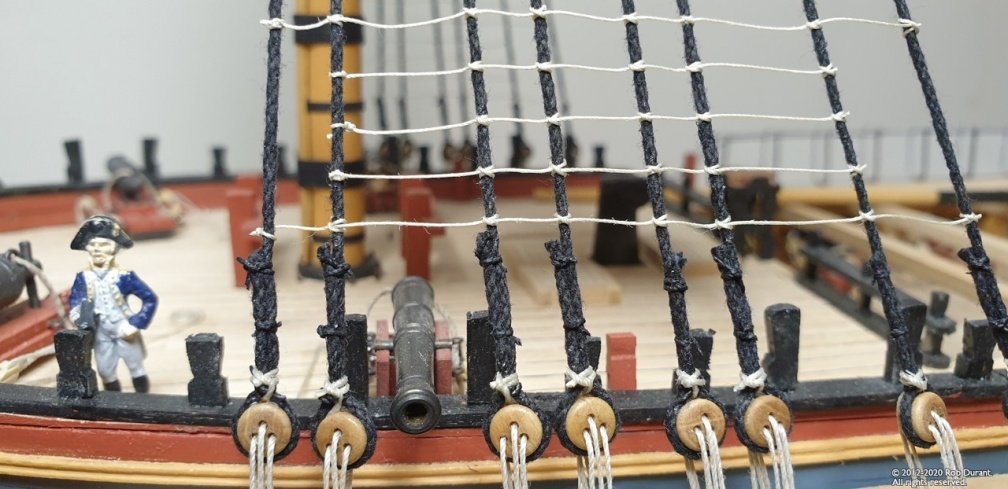
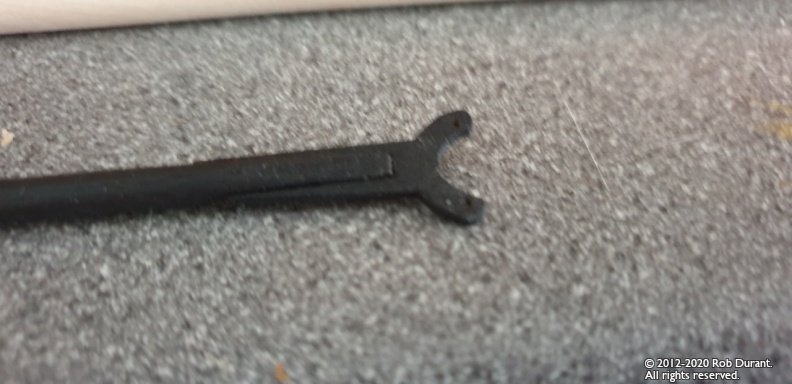
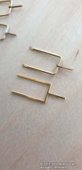
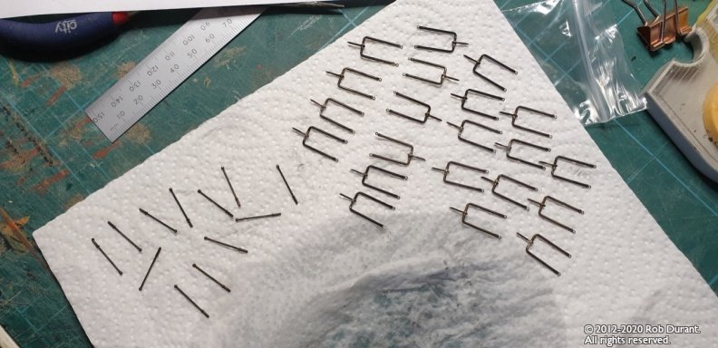
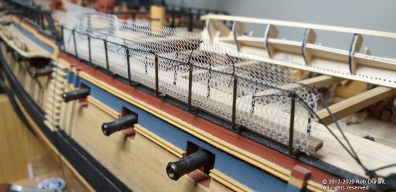
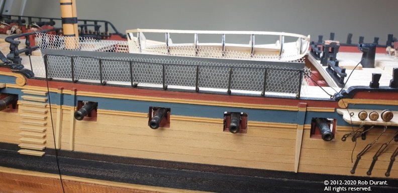
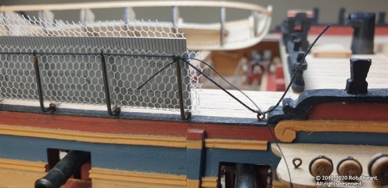
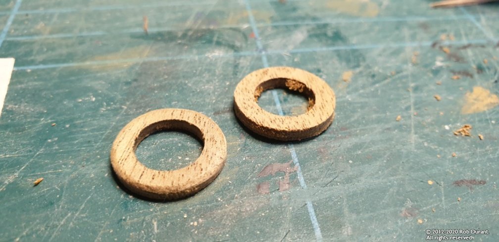
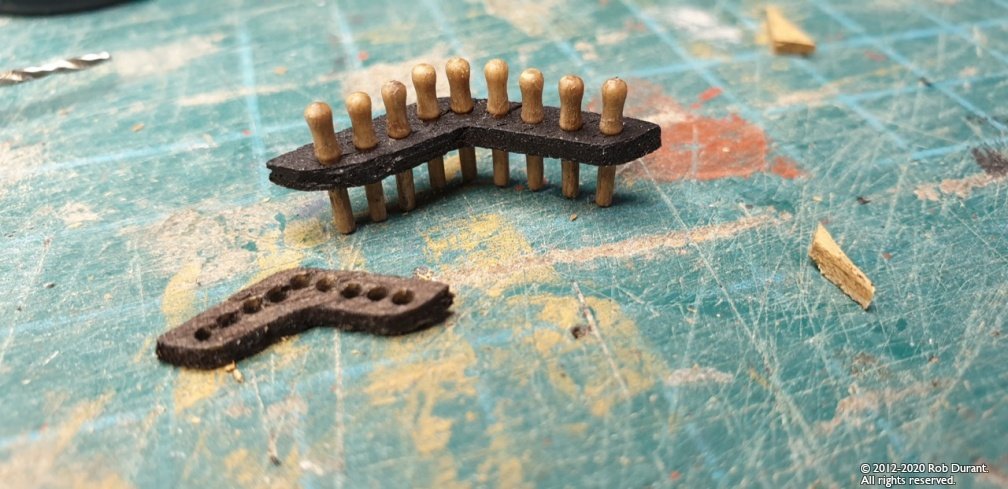
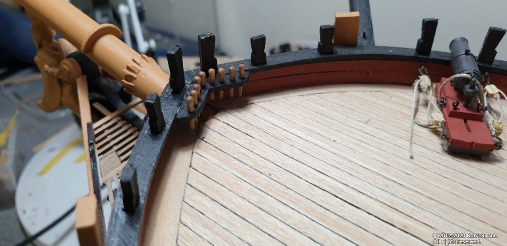
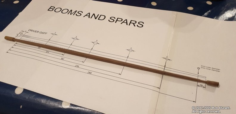
Thanks so much for the likes... I have some more progress to report. Driver boom - the jaw was completed (with considerable re-shaping - the kit part seems somewhat oversized to me), the boom painted, and the pin inserted to place it on the mast. The height of the boom above the deck was calculated based based on the gap between the taffrail and the boom when the boom was parallel to the waterline. (I calculated a reasonable gap to be 8mm). It was a bit fiddly, but I'm pleased with the results. (Apologies for the quality of the first photo) Hammock cranes - I don't know whether others have had this problem, or whether I was simply not gentle enough when handling the photo-etch, but a good number of the rings on the tops of the hammock cranes had been completely destroyed (or were entirely missing) on my photo-etch sheet. Rather than try and botch a work around, I decided to manufacture my own (with some trepidation). A helpful topic on this site (which I'm afraid I've since lost track of) mentioned some 1mm brass tubing that could be used. Having order some, it turned out to be 0.9mm. Coupled with the small caldercraft eyelets (as supplied with their Pickle kit) to make the rings, and some 1:48 stanchion ends for the uprights (I got these from John Haynes for Cottesmore, and they've come in handy again), I had all the components to solder up some cranes. Having worked out the dimensions in CAD, I decided that hammock cranes on the open-bulwarks would be somewhat vulnerable, and instead, I would just build the main ones for the waist of the ship. This also meant I had enough materials to get the job done! A jig was made to ensure all the cranes ended up similar in size using walnut glued to ply (so I could solder without melting things), then work began. The eyelets were crimped into the top of the cranes (this avoided superglue which didn't seem to hold very well, and could stop the brass-blackening working well. Below and to the right, the caldercraft part is below the home-brew part. Once done, the cranes were blackened, and fitted to the hull Lines rigged through the cranes, and the netting cut to size (slightly over). The netting is the modelling fishing net. I bought black and white, but white seemed to me to look better. It's not done yet, but I'm pleased with it so far. Thanks again for all the encouragement. Rob
- 275 replies
-
- 14
-
-
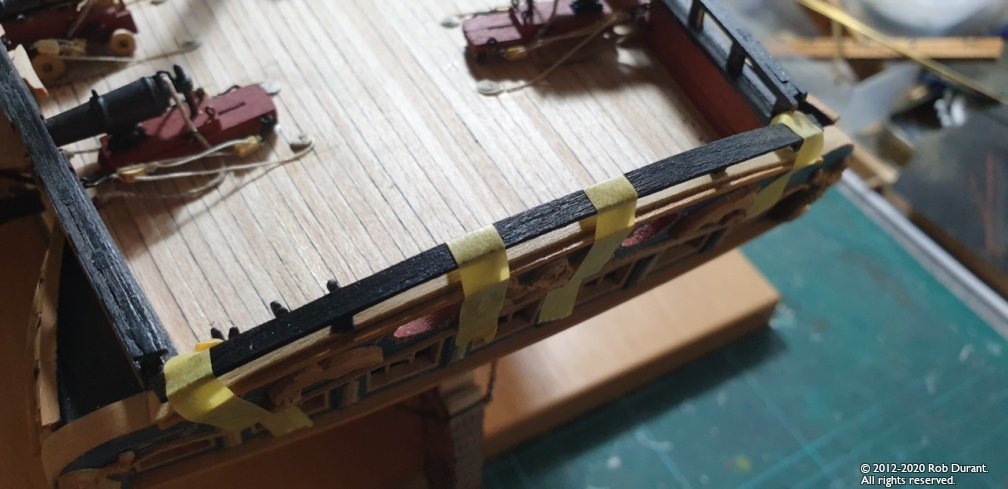
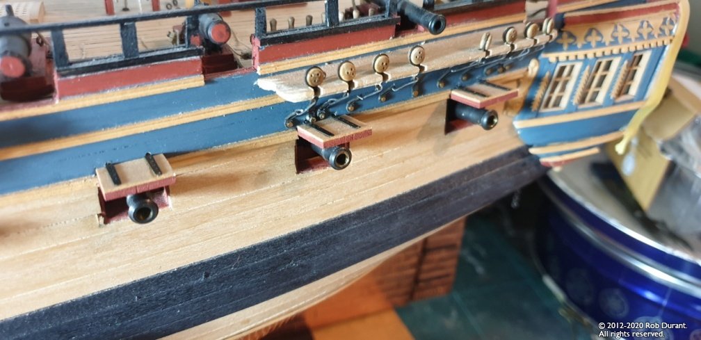
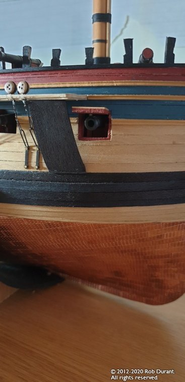
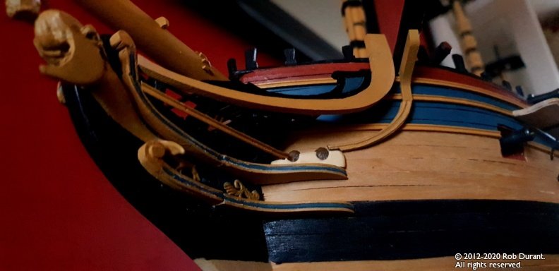
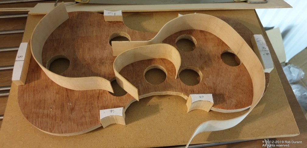
Hi all, Plenty of progress to report. I finally put the taffrail on. I used the violin rib bender to get the curve, which meant it was simply the right shape, and no force at all was necessary to stick it in position. Gunport lids The foremost gunport and three sternmost have gunport lids. These were planked with boxwood veneer, and then the blackened hinges were added. I looked at rigging them, but I wasn't confident I could do a job of this that would look a) to scale, b) neat, not least given the proximity of the chainplates and channels in places, so I opted to keep it simple and neat. Finalizing Channels I finally got round to filling in the gaps in the port side channels where the deadeyes are mounted. This was done with scraps of boxwood, and then the whole sanded gentle down to make neat. (This is stunningly boring stuff, so no pictures!) Mast bases I sanded, painted black and installed the mast bases. Bow pinrail Trying to insert the belaying pins into this part demonstrated that it was woefully small, and the pins were jammed against each other (probably because the belaying pins are somewhat oversize). Instead of trying to force the issue, I made a replacement pinrail which was a good 5mm bigger on each side. The results are below (with the original part just in front) The protective parts that stop the anchor damaging the channels (name?) were now put in place (stained with admiralty models ebony stain, as per the Wales) Since then I've been working on masts... but I'll put that progress in a separate post. Happy building Rob
- 275 replies
-
- 10
-
-
Hi Allan, Thank you so much for your quick and extremely helpful answer. As you say, the pictures say a thousand words. Not sure how I missed that diagram in AOTS. Now I feel confident to proceed. I wonder where the studdingsail yards would be kept when not in use? On the skid beams perhaps? So. For my model, I shall have the studdingsail booms represented, but as it is not rigged, the stunsail yards will not be there. Thanks again Rob
-
Hi, I've been looking through the Anatomy of the Ship book for Diana, as I prepare to turn the yards for my model. I notice that in the spar dimensions table, it mentions both studdingsail yards and studdingsail booms for lower, top, topgallant on both main and fore masts. I had assumed that the boom was the yard, so clearly I've misunderstood something. Both are in addition to the yards themselves, which have their own entries. For example, the main lower studdingsail boom has a diameter of 9 1/4" and a length of 45' 8", and the main lower studdingsail yard has a diameter of 5 1/4" and a length of 26' 1", so they are clearly different spars. Could anyone shed some light, please? Many thanks Rob
-
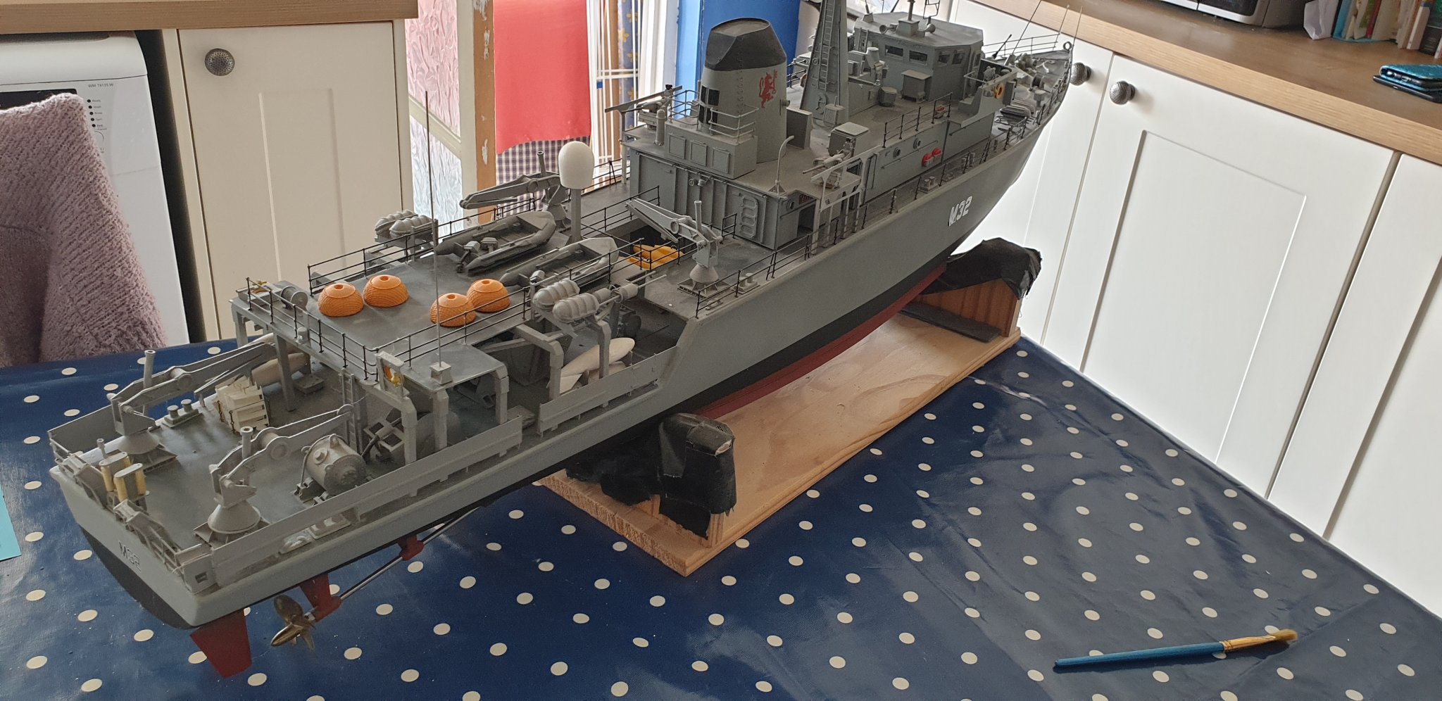
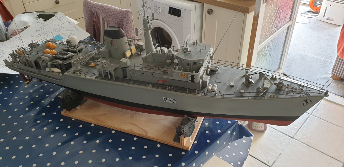
Wow - that post made me sit up... Hope you don't mind me adding a few pictures of the last (very dusty) radio controlled semi-scratch model I built... (Also HMS COTTESMORE, in 1:48). Fascinating vessels. That's a beautiful waterline model of her!

-
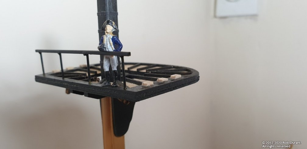
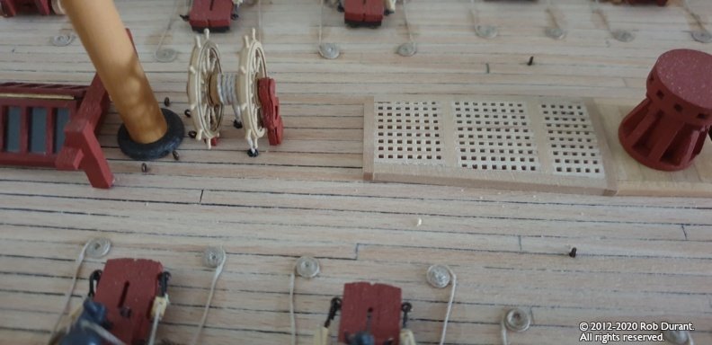
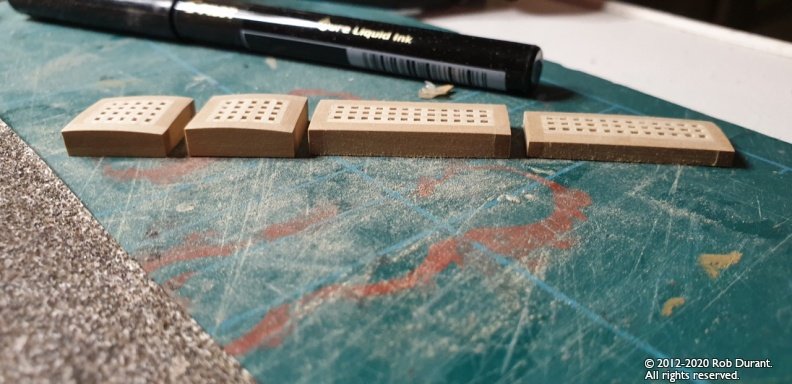
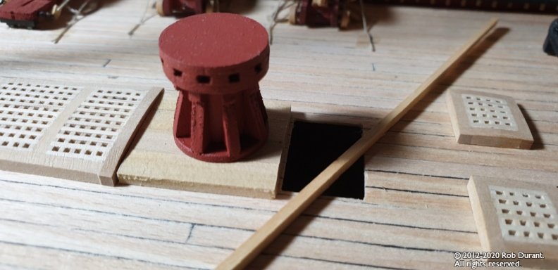
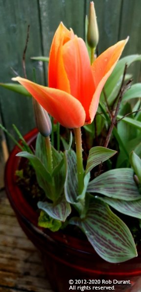
Thanks for all the likes, input and encouragement. I went through the NMM website to try and find that plan of the Diana Main Yard in their collections, but couldn't for the life of me track it down. Anyway - there it is in their prints site. Given that plan is 80cm across, I make it 38.5cm across at 1:64 scale... and 24.6m across full-size (AOTS translated from 1:96 (26cm) to 1:64 measures 39cm so that's close enough for jazz). That's a serious bit of kit! A quick search tells me that Victory's main yard is around 31m (I remember last time I visited Victory being very struck with the scale of it, struck down on the ground next to Victory's hull, it runs a fair bit of the length of her (57m?) !) I'm sure in a high sea / winds, 12 metres felt like an awful lot longer to climb out. A question: The TopGallant masts have different types in AOTS (called pole heads?) - what were those different pole heads (stump, common, long) for? Was it different wind conditions? Whim of the captain? Progress so far has been in bits and bobs this evening... The gratings have been sanded down to height - the following shot shows the before and after left to right... The gratings have now been fixed in place, save the one next to the capstan platform, which I've also been working on (using some boxwood from an old ruler which is being gradually repurposed for the coaming surround for the capstan platform and gangway). I've also FINALLY completed making up the blocks and tackles for the carronades and guns on the foredeck, so those will be fully rigged by the end of tomorrow. (Trust me, that's way too repetitive for a photo... just look back through this topic for other similar things going on) I've been gradually planking the 32ft pinnace with what I think is maple veneer... It's painfully slow going, but I'm making progress slowly. Photos to follow shortly. Finally, I hope no-one will object, but I figured some photos of lovely things happening in the world might encourage us all... so here is a pleasant surprise from a pot I forgot about in the corner over the winter... It's my day off tomorrow, so I hope to have more to share with you all then. In the meantime, happy building, and God bless. Rob

-
Wow... what an amazing plan... that is totally going to be a part of my build now Thanks so much! Interesting that none of that detail is shown in AOTS. I wonder how many of the yards had woolding? Rob
-
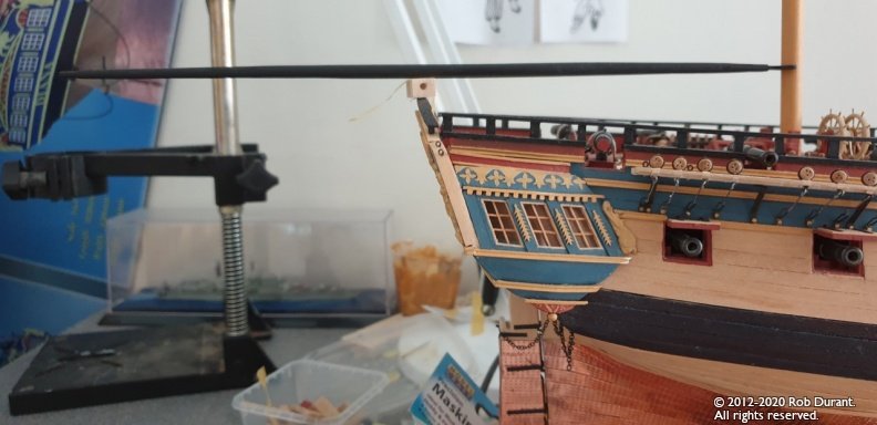
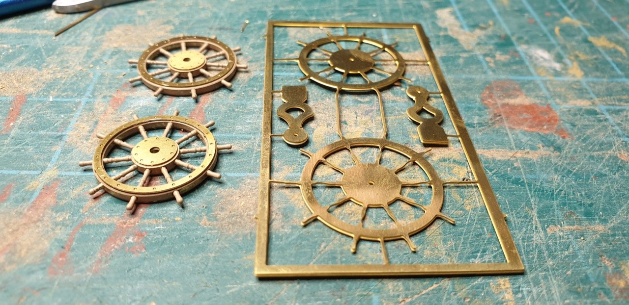
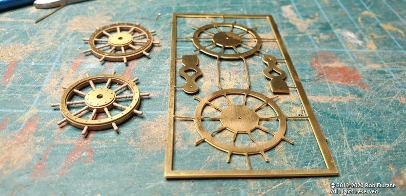
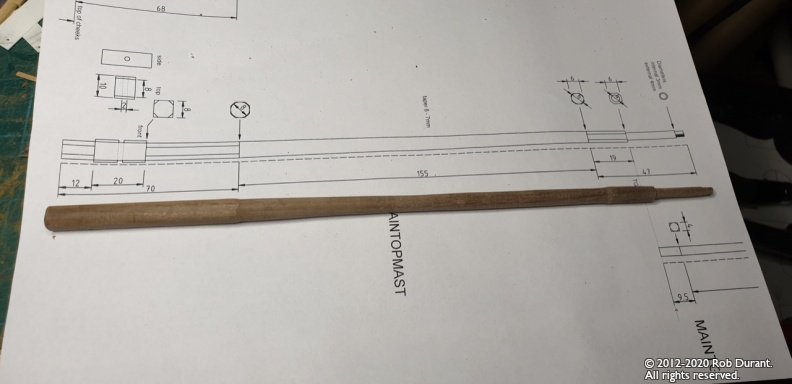
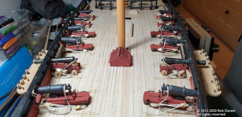
Wow. A lot has happened since I last posted. And some of it in the shipyard. I paused work on the tops, and have worked on the following: Rigging quarterdeck guns and carronades (complete) (There's some weirdness going on with the wide-angle lens on the photo below - the carronades aren't sloping down like that in reality) Finish off bow rails (the rails that lead from the cat heads are particularly tricky - I wanted to make my own parts, but it's added a few grey hairs along the way.) These are now fitted and complete. Rigging fore-deck guns and carronades (in progress) Shape topmasts (foretopmast and maintopmast done) and dry-fit with fids, and start looking at the cross trees Shape driver boom for mizzen and jib boom to assess out full length of model when complete. (complete) Make up belfry, barricades for fore-deck, and mount along with galley-chimney, quarterdeck capstan and hatches (complete on fore-deck). This involved sanding down the height of the hatches significantly as originally I made them the same height as the gun deck hatches, which looks odd. I've decided to live with the width of the coamings being too wide... It's too tricky to sand these down evenly without power tools (which I don't have) Replace kit supplied ship's wheels with the after-market Caldercraft 24mm ship's wheel. I've always felt the kit supplied wheel was somewhat insubstantial as a single layer of brass etch... This substitution was WELL worth it. I have a picture of the difference below. (Kit on right, after-market on left) All in all, I think I'm getting close to topping out the hull, and the focus will be much more on the masts, spars and rigging pretty soon. Very happy building to you all. Rob
- 275 replies
-
- 12
-
-
Wow Peter, this is great progress - you'll storm past me in no time. That gun rigging looks really neat! I used Casey's Brass Black and didn't have any problems with the blackening rubbing off afterwards, although I did read that it needs to be a thin layer, otherwise it can cause problems. I did find the brass black brilliant for all the eyelets that are required... painting them didn't appeal somehow. I did the whole batch in one go, along with lots of the photo-etched bits, so they're all ready to use now. (Nasty stuff, that brass black, mind you! Definitely one for goggles and gloves!)
-
Hope you feel better soon Chris. Those stunning pictures of HMS Bristol on your website keep on grabbing my attention. If you were to make a kit of her, I think I'd find that very hard to resist! With that said, as I watch others building your new kits, pretty much any 1:64 frigate kit designed by you would be like a syren calling, too. (And I was so sure my next build was going to be something smaller!)
-
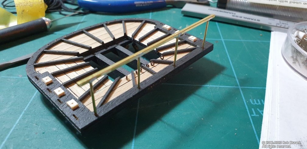
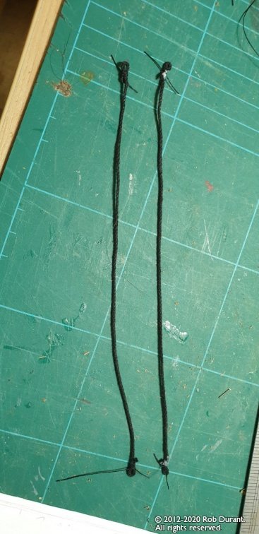
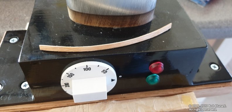
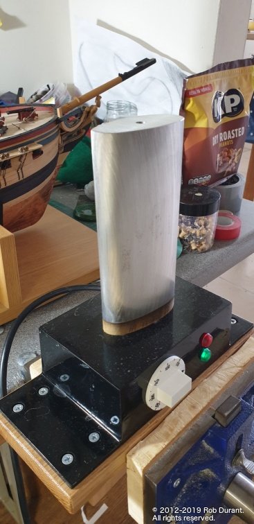
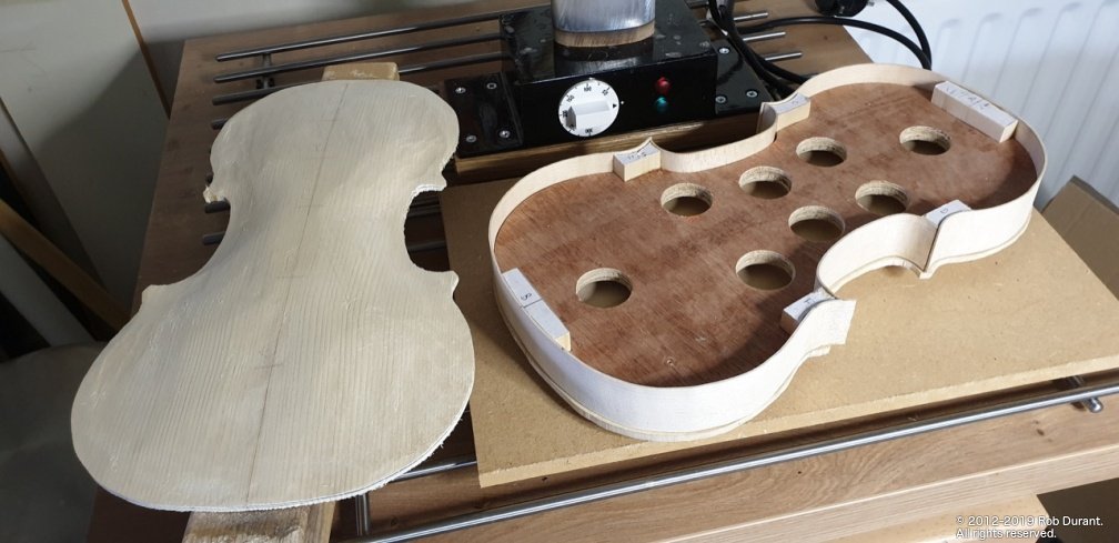
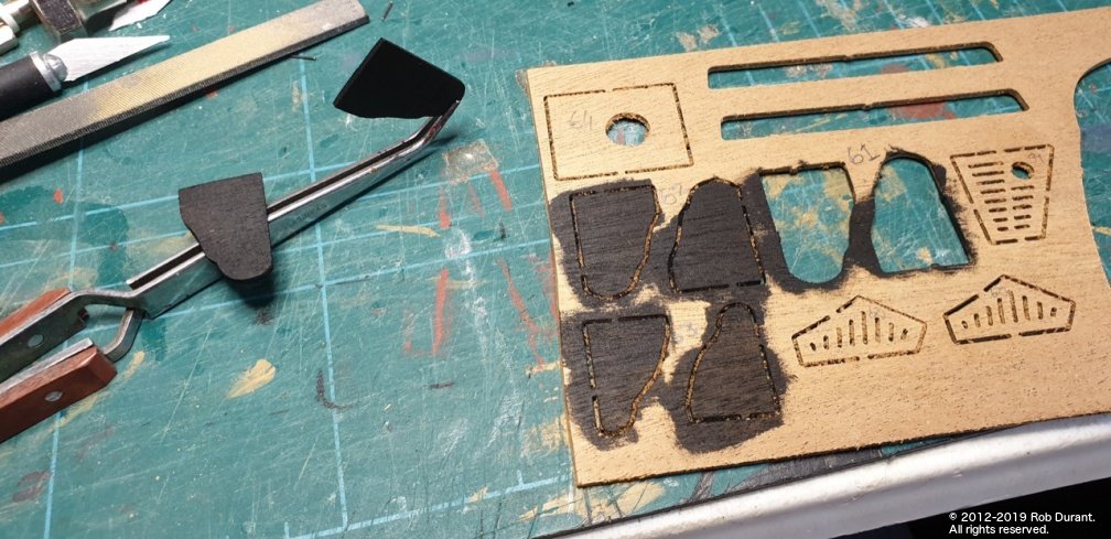
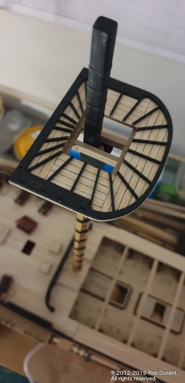
Hi Barbossa, OC, Thanks for the likes and encouragement. Yes, I was really pleased with how the contrast worked out. Having looked at the AOTS book and seen the planking marked, it seemed like a good choice. A little progress to report on the tops. I've added the eyelets, and the cross trees with holes for blocks underneath. I may have mentioned that I was a little concerned because the fore and mizzen tops had a bit of a twist in them that was about 3-4mm from side to side... enough that it was irking me. Well, I've recently acquired a rib-bender to help me in a new hobby I'm dabbling in - making a violin... and it turned out to be perfect to steam these parts straight. At 250 Celsius, with water applied to the underside of the top, I could infuse the part with steam, and it became malleable and I was able to hold it flat until it cooled. Not sure I'd recommend it just for fighting tops, though! (I've included two sneaky pics of my first bash at bending violin ribs... It's rough and ready, but I'm learning! Amazingly, once the ribs are bent, they simply hold their shape. There's no force at all necessary to get them to stay put.) Anyway - back to Ethalion! I've also continued making up the training tackle for the quarterdeck armament. The tops dry-fitted in situ. Rib bending iron used to flatten out the misbehaving tops... \ My first attempts at something new! The main top with eyelets and swivel gun bases added. Also, the paint has been touched up around the edges. The view from above gives a little idea what it must have been even only at the top of the main mast when working these ships! Holes drilled for the blocks... And more blocks for the quarterdeck armament... 24 pairs to do, of which 14 with rope, and 7 without rope are complete so far... I've lost count of how many times these have pinged out of my fingers. A real exercise in patience, but I'm on the home stretch with the guns now. Right. That's it from me for this evening. Rob

- 275 replies
-
- 14
-
-
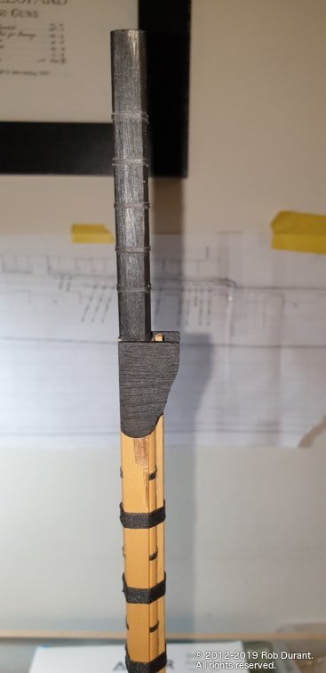
Oh, how disappointing. I typed out the whole message, and then it disappeared when I hit Submit... Oh well. Let's have another go. Thanks so much to everyone who has offered likes, encouragement, advice... it's so helpful, and a great spur to keep going on what is now a four year project! I've been busy rigging the weapons on the quarterdeck - not much to show, really... breeching ropes, and training tackle, just like the gun deck. All the breeching ropes are fitted, then I use watered down PVA to fix them so they look like they're falling naturally (or at least that's the plan). In the meantime - as I wait for the glue to dry so I can have my tools, which are keeping them in place as they dry, back, I've been working on the crosstrees. That meant first fitting the cheeks to the mast. These were pre-painted so that the lines between the black and the ochre were really crisp, then glued in place. The crosstrees are glued together, but not attached to anything yet... However, dry-fitted it all goes together really nicely... Here are the pictures... Thanks again to everyone who looks in, and happy building! Rob
- 275 replies
-
- 12
-
-
Thanks OC. It is a fabulous model to work on. My only problem with it is that I simply can't find the boat to follow it with. This really was - and continues to be - my dream build. With that said, some of Chris Watton's future offerings look very tempting. It would just be a question of space. Having build a Frigate, I don't think I'd want to do anything with more guns. I find the the repetition is somewhat wearing beyond a certain point. I'd also need to find somewhere to put them! Anyway - plenty of work still to do on this one yet.
-
That would make perfect sense... it would also explain how they avoided that area becoming horrible cramped when rigging the guns... it really is quite a challenge to fit it all in (especially if the carronades are going to have training tackle going diagonally out from them - which I neglected to think of until all the holes were drilled!). Having got all the pin rails in, I think I'll have to live with it now. Not sure I'm brave enough to try and undo all that, and get it sanded, painted without messing up the deck. Thanks for the encouragement. Hope you find some good quality maple soon. Rob