HOLIDAY DONATION DRIVE - SUPPORT MSW - DO YOUR PART TO KEEP THIS GREAT FORUM GOING!
×


robdurant
-
Posts
842 -
Joined
-
Last visited
Content Type
Profiles
Forums
Gallery
Events
Everything posted by robdurant
-
 I'm just starting to build the case for my Diana (Ethalion)... it was when I costed the clear plastic and realised it alone would be over 200 pounds itself that I realised I'd built a seriously large model (although crossing the main yard was a hint)... but cover it I will because already it's a challenge getting into the nooks and crannies to dust her and I have children who benefit from not having to edge round fragile models all day Vane, whatever you decide you're going to end up with a stunning fleet. Your skills are very evident in all your builds. Oboship... have you considered rigging the yards braced round, or even building her as an admiralty model without the masts or rigging? (The much smaller option) Both would be preferable to not finishing?
 -
Wow. You're doing a wonderful job with this model, and at 1:96, too. Very impressive. The chestrees and fenders do add that bit of detail to the side, don't they, and you've executed them really well. They look like they've always been there.
- 142 replies
-
- 3
-

-
- alfred
- solid hull
- (and 2 more)
-
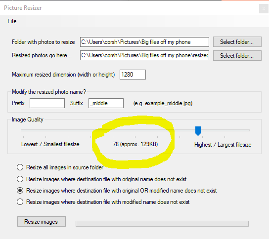
Hi all, A quick update. I've just released version 1.0.4, which has a couple of minor bug fixes and introduces application icons and a few other touches that will make the programme look nicer on your computer. Do uninstall the previous version first, then you can find the application here: https://www.durant.biz/pictureresizer/ v1.0.4 updates: * When you close the application it will now keep hold of your settings, and bring them up again when you come back. * The profile files now store the resize images option. * Application icons and installer graphics updated. Thanks Rob
-
Two years very well spent from what I can see Happy new year to you too!
-
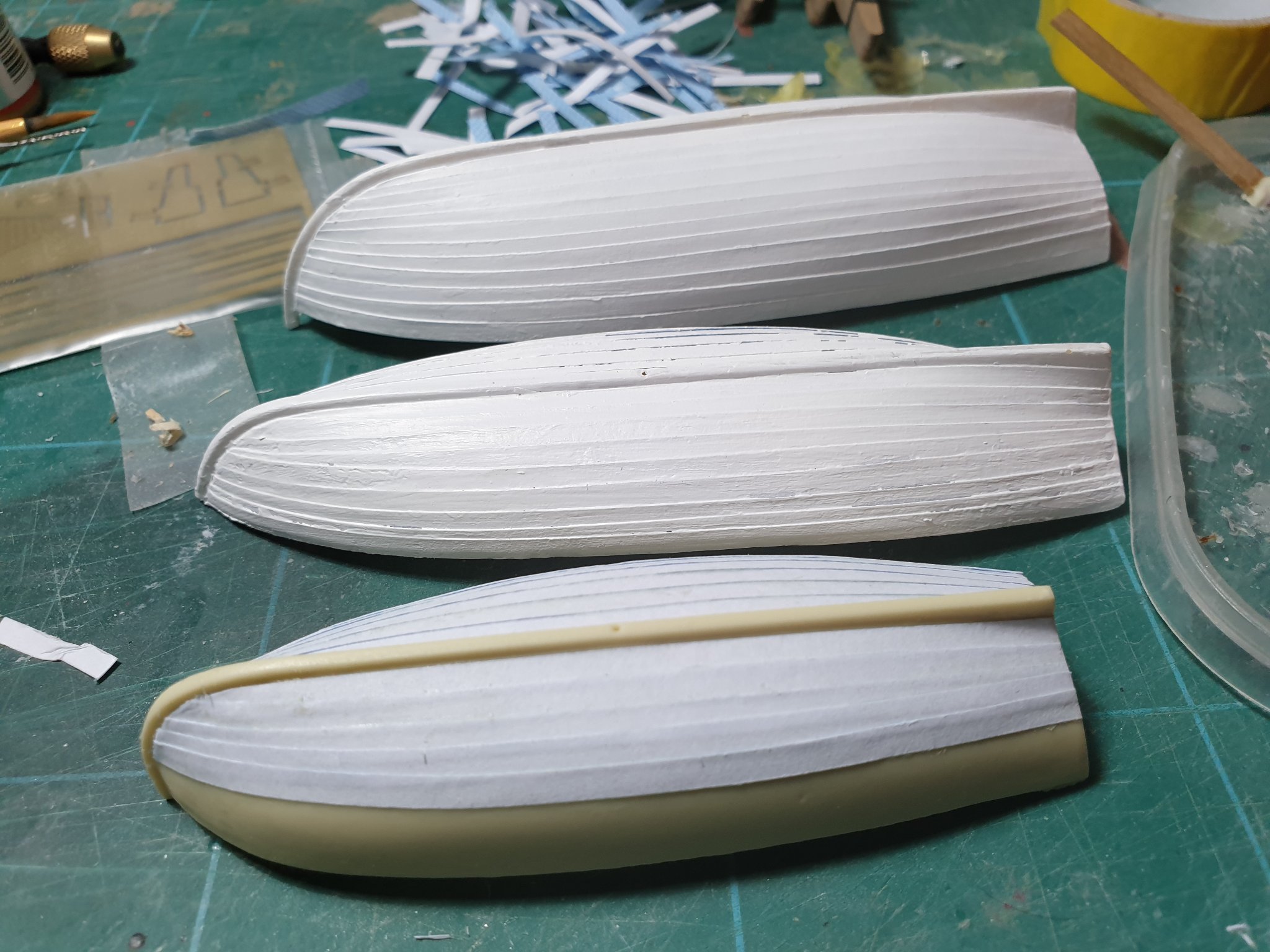
Hi Peter You spotted them They were a gift from santa... I really struggle making the wooden little boats so I now have the resin hull set sold separately. I spent a happy few hours yesterday evening putting paper onto them as per Jason's (beef wellington) build to make them look clinkered. Having put them in place I now realise it will leave almost nothing showing on the gundeck so I'll probably display them along the front of the model with perhaps one in place. We'll see. Here's the progress so far. Thanks Rob

-
Okay - so just looking back at what I did yesterday, I'm still getting confused myself... Here's what I did, using the mizzen mast as the example (the main mast is the same) 1. Mizzentopmast stay. Goes to the block just below the mainmast top, then passes down to the deck where it is secured as shown. 2. Mizzentopmast preventer stay. The same, but goes to the block above the mainmast top. 3. Mizzentopgallantmast stay. Goes from the hounds of the topgallant to the block on the maintopmast just above the crosstrees, then passes down to the top where it is seized to an eyelet. 4. Mizzentop royal stay. Goes from the tip of the topgallant to the block seized round the hounds of the maintopgallant mast, then down to be tied off on the mainmast main shroud behind the mast. Then rinse and repeat for the main mast, tying off to the fore mast in the respective positions. As always, hope this helps Next post will be on the (somewhat confusing) array of backstays that can be fitted... Happy building Rob
-
Oh yes, and a picture of progress so far.... (with the yards temporarily fixed to see how it looked ) And one with just the rigging...
-
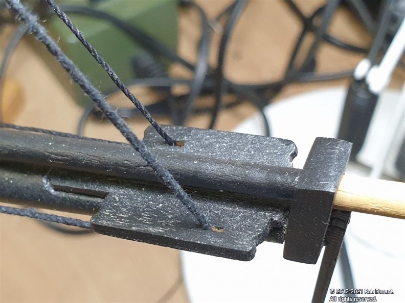
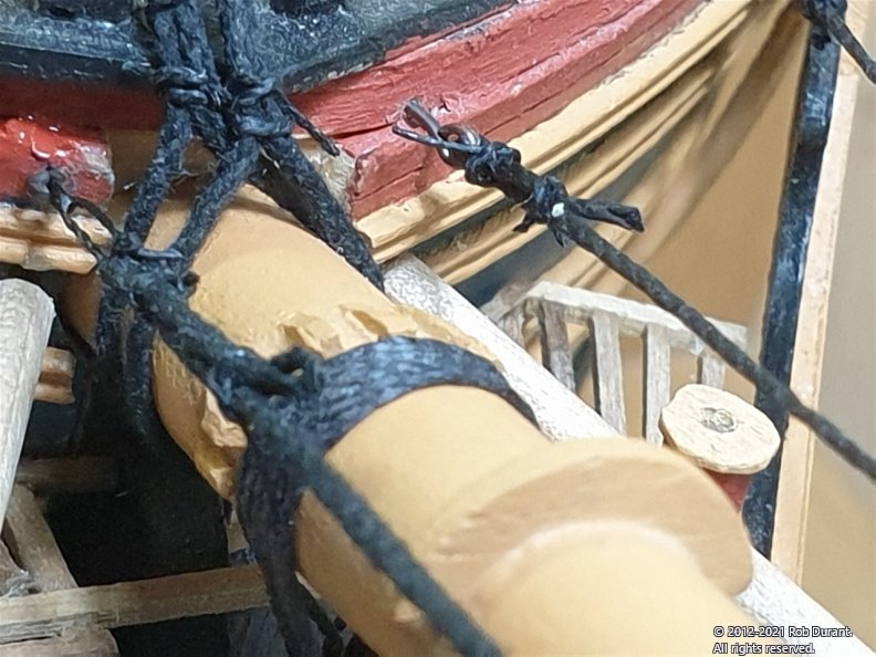
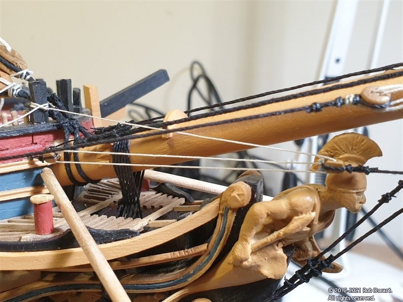
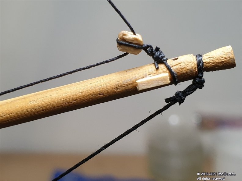
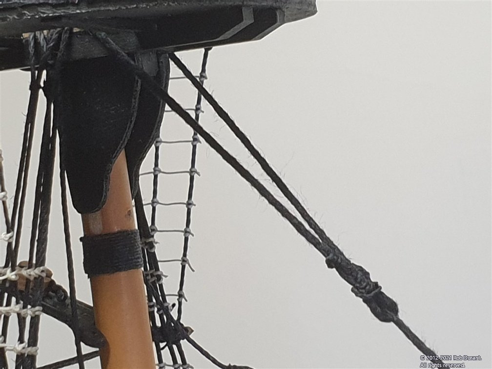
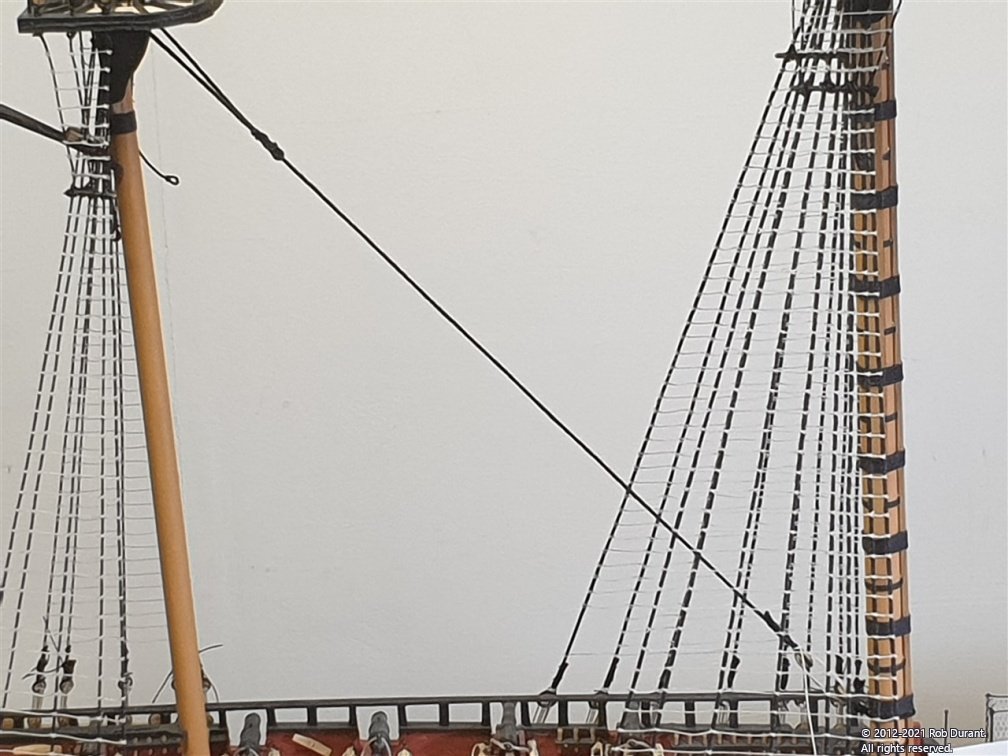
More stays, a martingale, and some backstays... Once the lower stays are in place, it's time to move onto the backstays. These are set up much like the lower stays, except that the foretopmast stay and the foretopgallant stay go through the holes in the bees on either side of the jib boom. They attach to eyelets in the bow on either side of the jib boom, where they're seized. These photos are warts and all, but hopefully it allows you to see how I've gone ahead and done things. I rigged the martingale next... This is the rope that goes from the tip of the jib boom, under the dolphin striker (that points down from the joint between the jib boom and bowsprit) and to the bow. Foretopgallant stay This goes from the hounds of the foretopgallant mast down to the block on the tip of the jibboom and then runs back along the jib boom to tie off on the starboard deadeye on the foremost ring of deadeyes on the bowsprit. The main and mizzen topgallant stays and royal stays, go to the mast in front where they pass through blocks and down. The top gallant stays go to the deck where they are fixed with blocks... the royals, are tied off to the back of the main shroud. For some reason I didn't take pictures of this, so I'll try and get some and add a post. All of this may not be entirely accurate to the period, but it's how I'd gone about it based on my understanding of the plans and Lennarth Petersson's book. Hope it's helpful. Rob
.jpg.52e11ae3120c630e7af29643386bd39c.jpg)
-
Thanks gsdpic. And welcome to the build.
-
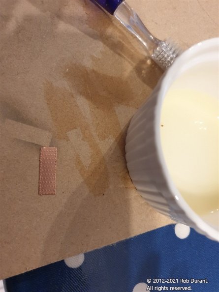
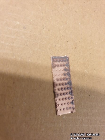
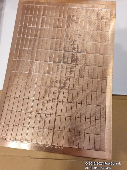
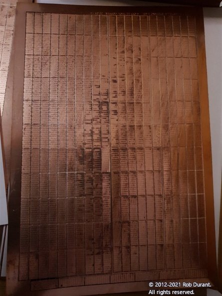
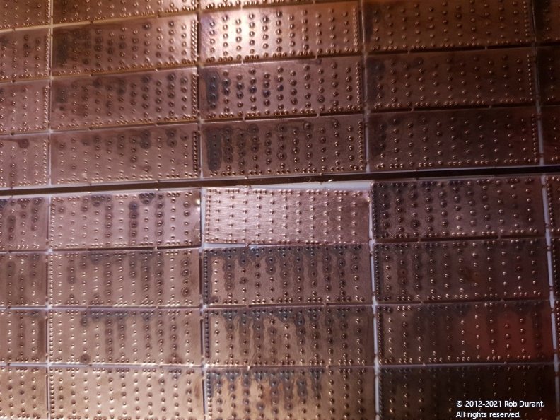
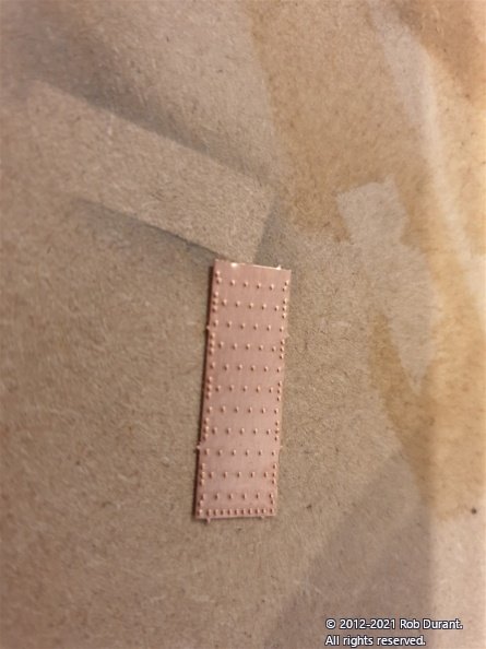
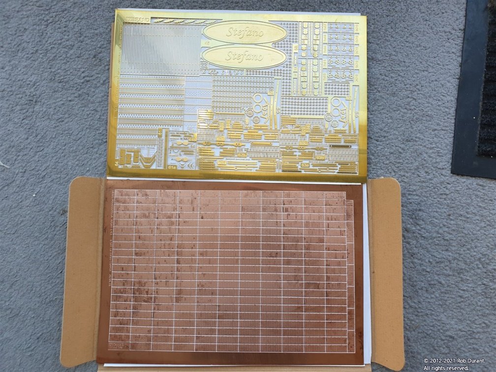
Thanks Chris I mentioned above that the copper plates provided had fairly significant marking across each of the sheets. I was reasonably confident it would come off, but didn't want to leave it until I came to the point of wanting to install them just in case I was wrong. Well, here are the results of my test... 1. The whole sheet before testing... (as it came in the box) I cut out one tile to experiment on from the centre of the worst marking. Here's a close-up... 2. Test one: Acetone (nail-varnish remover) The first attempt to remove the marks was with acetone. Despite bathing the tile in the acetone (in a sealed container for about five minutes) and then scrubbing it with a toothbrush, this seemed to have absolutely no effect. The tile ended up looking precisely as it started, when compared to the sheet it had come from. 3. Test two: neat Lemon juice The second attempt was using neat lemon juice... and scrubbing gently with a toothbrush. (The detail on the etching is so fine, it shreds tissue paper, and I was concerned I'd damage the tiles) This method provided almost instant results. Within 20 seconds the tile was completely shiny, as I would hope - all marking entirely gone. I was conscious that the active ingredient is citric acid, so I rinsed the tile afterwards in plenty of water to remove the acid. Here's the tile on it's own... And in situ to compare to the rest of the sheet... And... I'm much more confident it's all going to be fine now, so I can pack it all away and concentrate on Ethalion Take care, and a very happy Christmas to you all! Rob Update: Zoran from MarisStella has helpfully pointed out the putting the sheet into Coca Cola for a few seconds, and then rinsing with clean water will clean the copper well, too. Thanks Zoran
-
That's very generous of you, thank you. I hope I can do it justice, but I'm relishing the challenge.
-
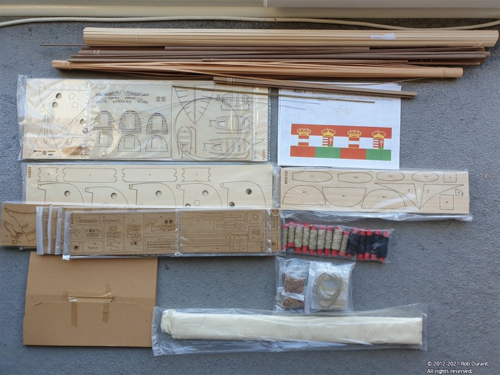
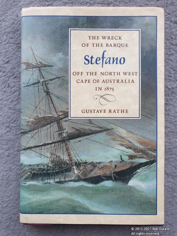
You're very welcome Jason. As I said, it might be a few weeks before I really get going on this build, as I must finish Ethalion In the meantime, here's some pictures of what you get in the kit: In the shot below, the laser cut sheets are all stacked up - there are LOADS of them, all of which look beautifully cut. I figured I wouldn't give anyone looking to knock off this kit a head start, but they look good! A nice uniform colour to the walnut, too, which will help as we move ahead. Note as well, bottom right are the pre-sewn sails - again the sewing is very fine, but I haven't had the material out of the pack yet... I want to keep it clean. I've only done sails out of tissue before, but I was pleased with that effect. When the time comes, I shall offer them up against each other and see which I feel will give the better outcome. Nice to have the option, though, and this model WILL be fully rigged with sails unfurled. You can see the black marking on the copper plates - this marking is on each of the numerous sheets. I'm not too worried about this. I figure when the time comes I can get it clean with some acetone. We'll see. And finally the plans... and plans... and plans... all beautifully detailed. Again, I don't want to give anyone wanting to copy the kit a headstart, so I haven't shown the contents here. Doubtless snippets will appear as the build progresses. I've never seen such detailed plans on a kit. They really are lovely, so I suspect this aspect of the build will be an absolute pleasure. I'm a sucker for a nice plan! Finally, a picture of the book by Gustave Rathe, grandson of one of the people onboard the Barque when she sank. I'm looking forward to reading this in preparation for the build. That's it for now until I finish Ethalion Happy building! Rob p.s. my ten-year-old son has just demonstrated he can climb inside the box this kit was delivered in and the lid pretty much closes.... Are my builds getting over-ambitious?!?!
-
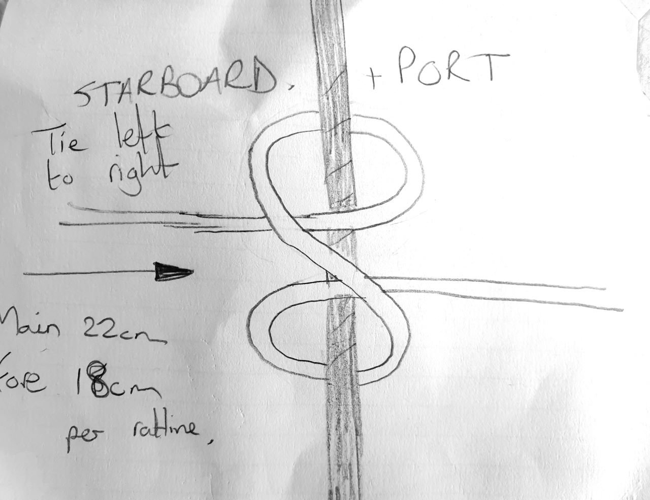
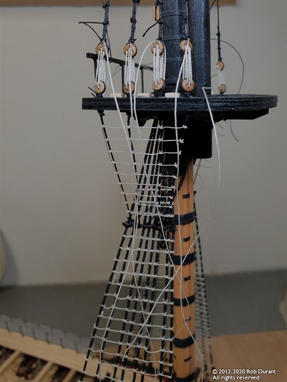
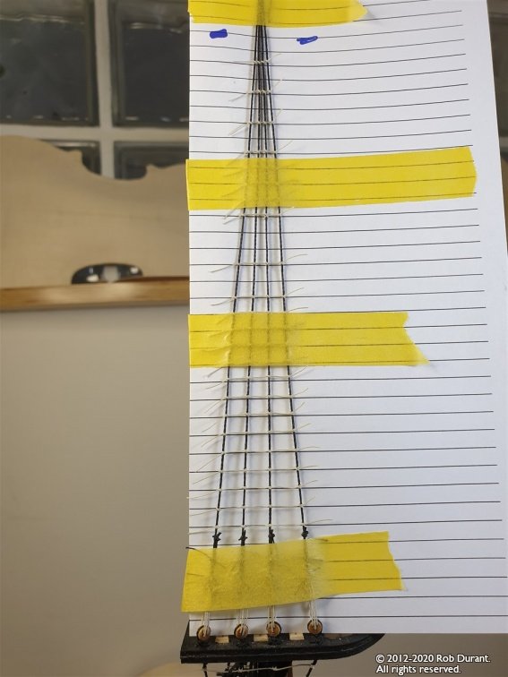
Thanks Tim, Yes, the knots are clove hitches. At first I always have the following picture next to me while I'm tying them otherwise I get confused. By the time I'm half way up the first shroud, I pretty much have it under my belt again and I can get into the rhythm. When it's right, you get one line across the front, and two across the back. It looks really nice Tweezers are a must, and after each row, I put on watered down PVA. I go up the sections from bottom to top, every other line, and then go back the next day and fill in the other lines. As I go, I watch to see if the shrouds are being pulled out of line (using pencil marks on the paper behind, made when i put in the guides), and then gently pull the lines (which at that point still have some spare on either end) to fix it. Once the whole shroud is done, that's when I go back and cut off the 5mm or so I've left on each end of each line. I've learned to leave that little bit, as on Pickle, I didn't, and occasionally I'd undo work I'd done earlier, much to my frustration.
-
Well, the Barque Stefano kit arrived, so I've started the build log ready for her, but it's going to be a few weeks before I really get my teeth into that build, I think If you're interested you can find it here.
-
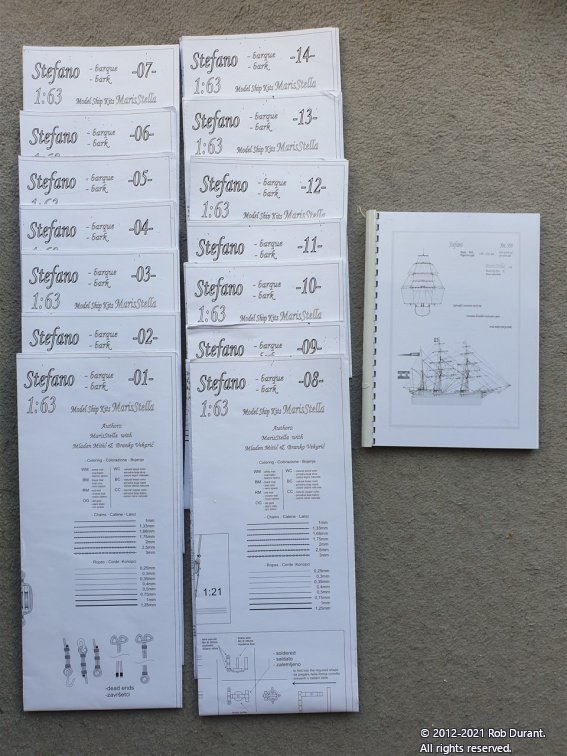
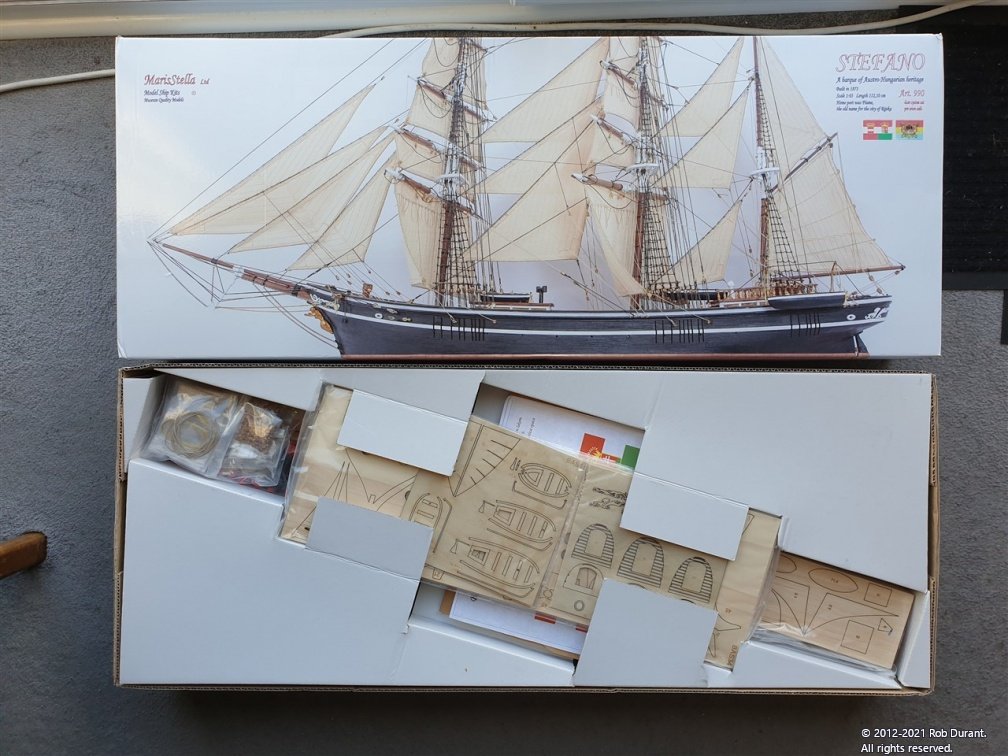
Hi all, As I draw to an end with Ethalion, I was thrilled and surprised to find that in these somewhat uncertain times of COVID, the model I ordered from Croatia arrived a day early. So - I thought I'd put an initial post in what looks like being another build log that will take some time. I need to finish my HMS Ethalion build first, so there may be a few weeks delay to getting started, but then we'll be up and running. What I can do in the meantime is give a few first impressions of both MarisStella and their kit, and once I've read the book about what happened to Barque Stefano and her crew I shall understand better why this is such an historically important vessel. If you want to know more, I'd recommend looking at the build logs of MarisStella.hr, and HeronGuy who have said more on this subject. The company I found the company a joy to deal with. Yes, they don't have a traditional payment gateway on their website, but they do live up to their claims as far as personal service is concerned. They were quick to respond to my initial enquiry, helpful with all my questions, and absolutely true to their word when I went ahead with buying the kit. From ordering to my door was six days. 1 quicker than they said it might be. I think that's enough said. The kit I can't comment on how the kit goes together yet... as I haven't started it. But the kit has certainly survived a long journey in excellent condition. I bought the upgrade version (as opposed to the retro version) It was in a good heavy, outer brown cardboard box, and the inner kit box is really nice with nice big colour printed image of the model. It's built to be good and sturdy with helpful and well thought out packing inside that keeps everything really well secured. The plans themselves are heavy! (14 sheets of well printed, clearly set out plans at the same scale as the model that at first glance look really good quality). The plan booklet contains a copy in good English, and various diagrams and schematics adding detail to the sheet plans. The materials look good at first glance - building the kit will give a better idea. The photo etch and copper plates were well packaged to give protection from the journey and arrived in perfect shape. The copper plates had some black marks on them, but I'm confident that this will come off with a little clean up. No big deal I'm sure. They are so finely etched that I'm really looking forward to fitting them. They have a lovely deep copper red lustre which should look amazing when fitted, and as has been mentioned before, they are -handed so will overlap as on the real ship (if I get it right when I build the model!). All-in-all, I'm really impressed. So. If anyone wants to join in the journey, please do. I'm pretty sure that being a more modern vessel there's going to be a bunch of metal work to do that I've never done before... but it's all part of the learning experience, so we'll make it. I'll try and take some pictures to go alongside these comments in the next few days. Rob
-
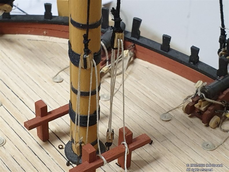
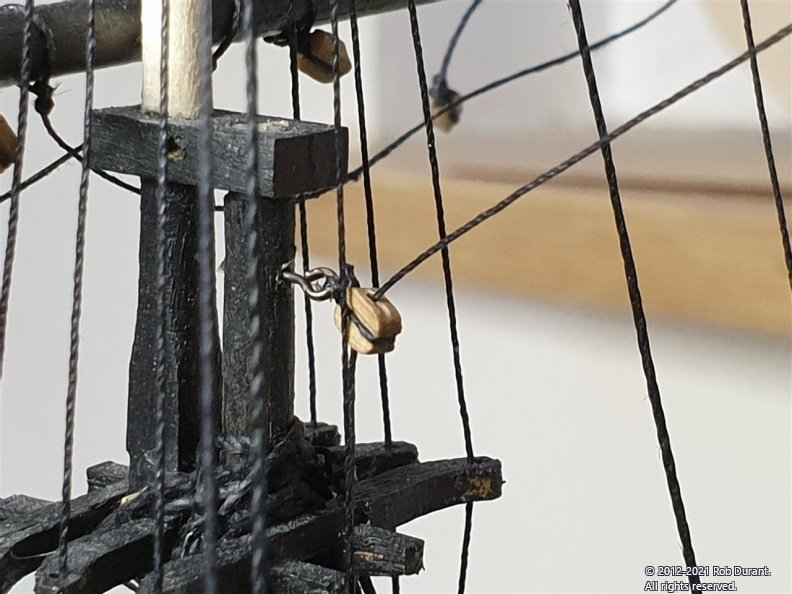
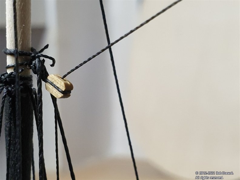
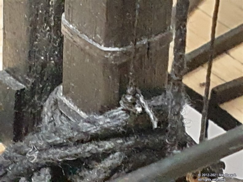
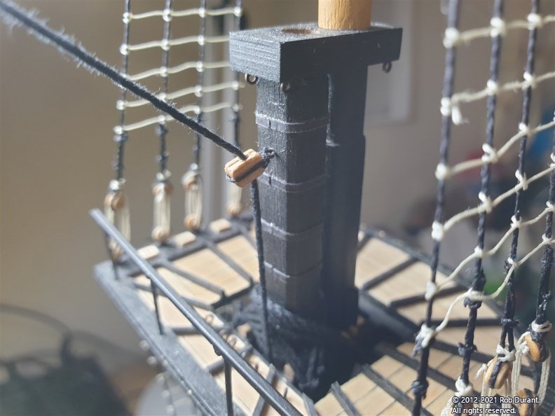
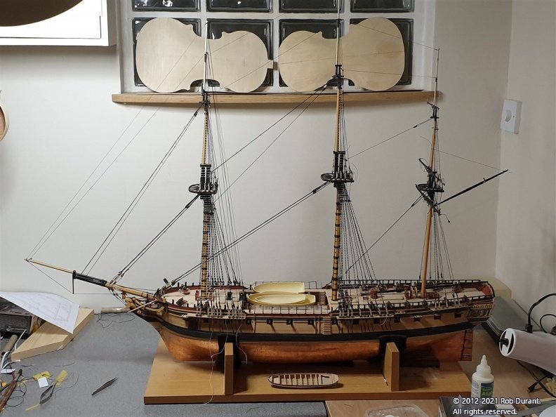
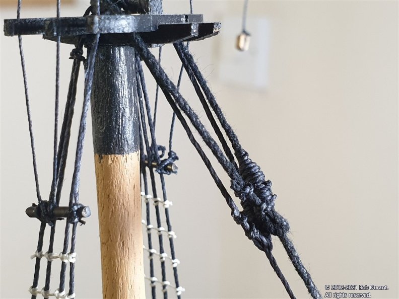
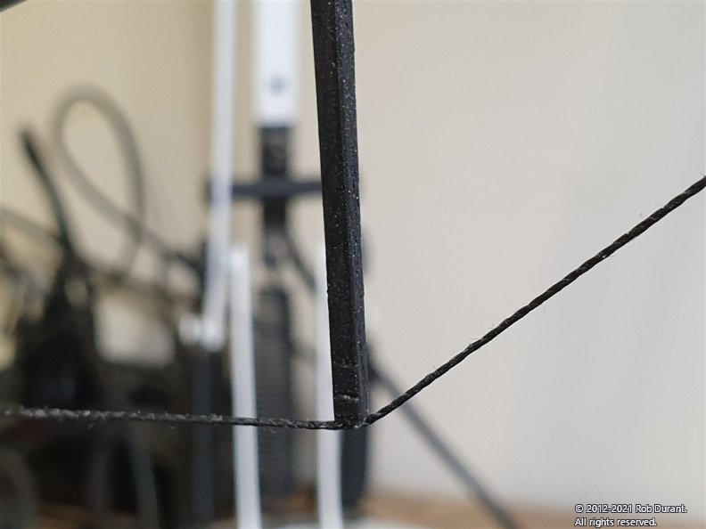
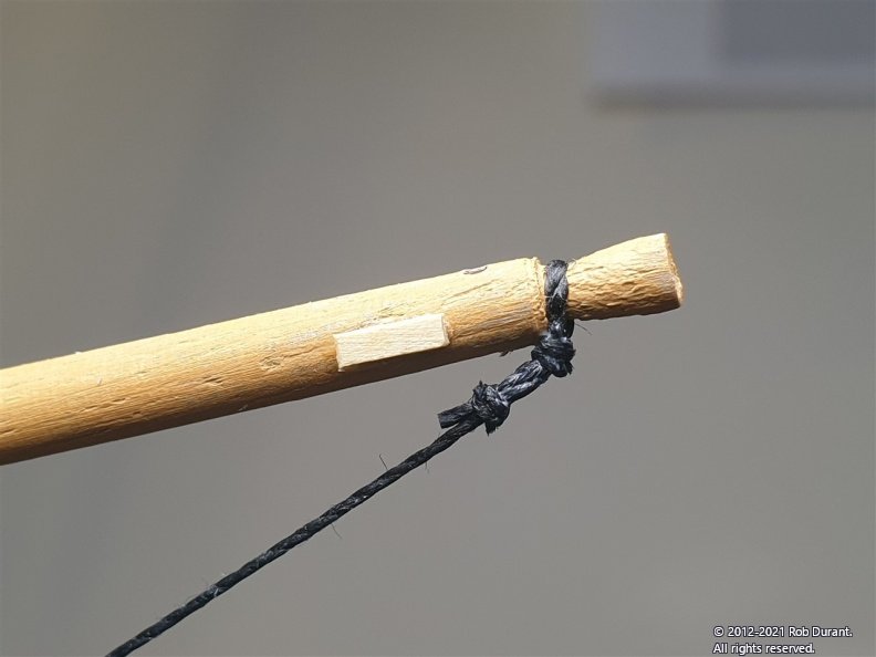
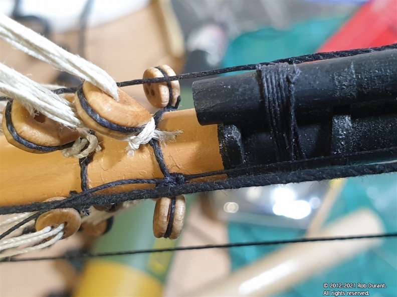
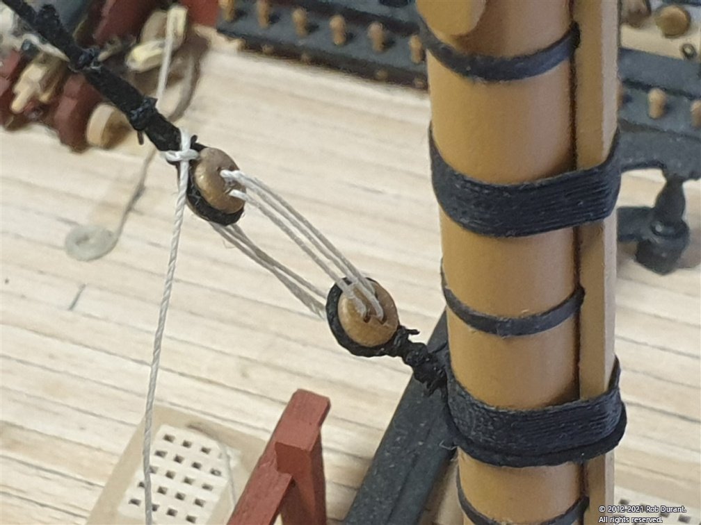
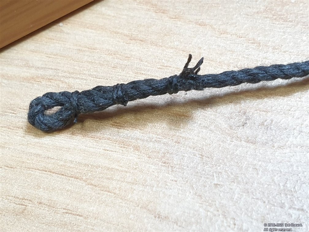
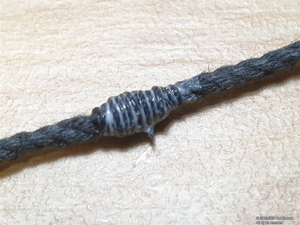
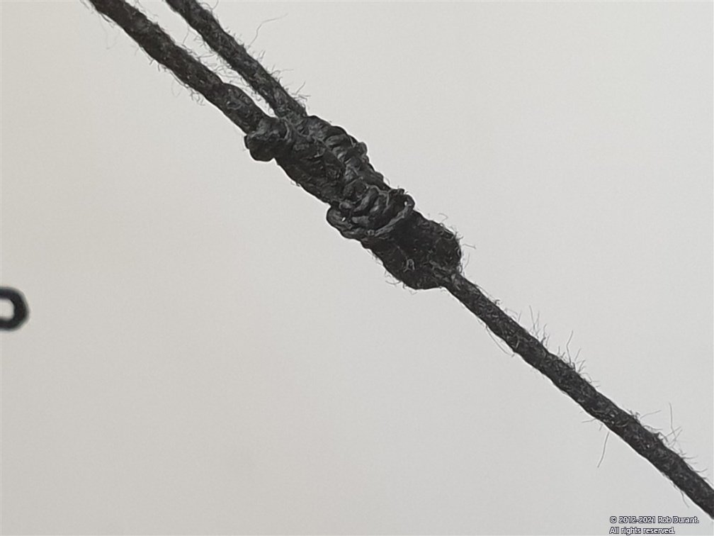
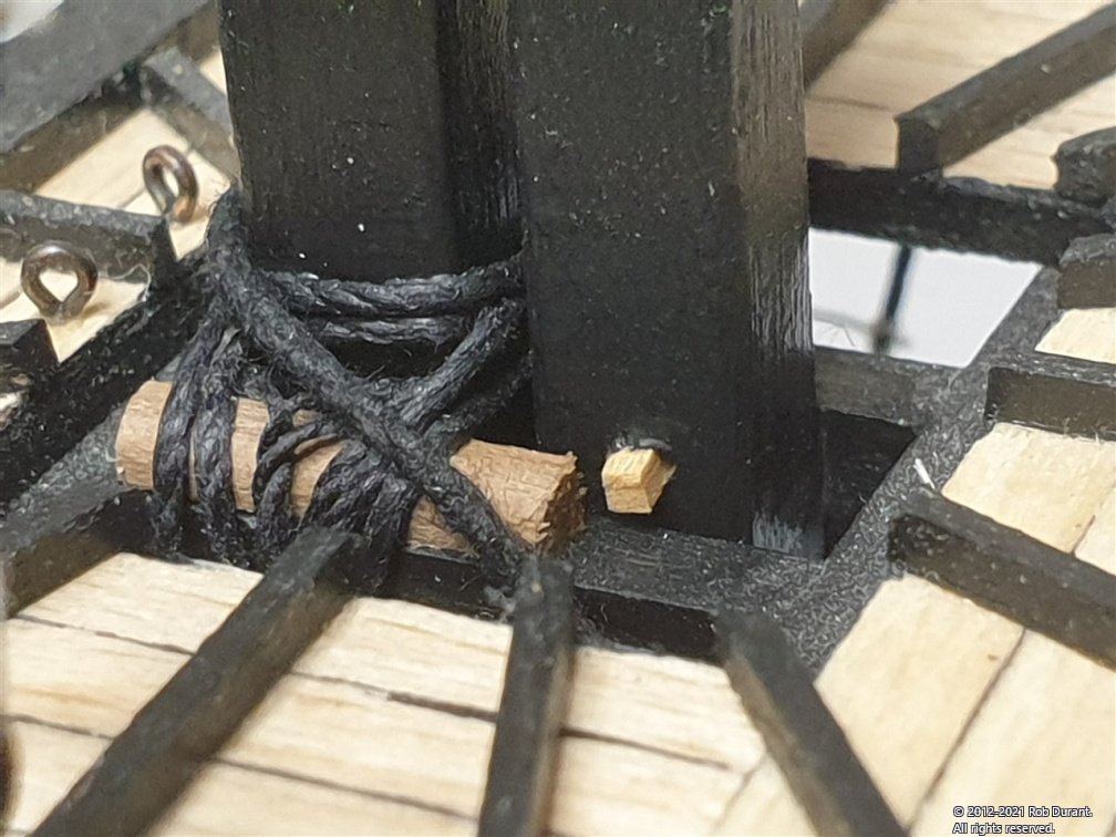
I had to pause and think for a bit here... I tend not to follow the instructions very closely. I'll read them through, then look at the other build logs, think about how I've done it before in other similar builds (i.e. Royal Yacht Caroline in this case) and then gingerly pick my way through. So, it was onto the standing rigging. I proceeded in the following order: Add shroud cleats to every fore shroud and the rear two mizzen shrouds, 12mm above the deadeyes. Add shroud cleats to the front two main and front two mizzen shrouds, directly above the deadeyes. Mizzen mast stay Main mast preventer stay Main mast stay Fore mast preventer stay Main mast stay Bobstays. And that's as far as I've got so far. Now, it wasn't clear on the plans, but I feel I may have got the hearts muddled up... I've used the two larger on the main mast, and the two smaller on the fore, but I suspect it should actually be larger for the main stays and smaller for the preventer stays? I don't know for sure, but it's done now, and I'm going to live with it. The mouse on each stay was made by tying .25mm thread round the rope, and then wrapping it around to effectively seize the rope back and fore, then carefully tying a couple of reef knots to secure. I used pva to help as I went. Here are some photos of the work done. Shroud cleats: I found that tying a knot round the shroud cleat in the upper notch first, then tying this round the shroud, and then tying another knot round the lower notch provided a reasonable amount of stability. This worked better on the main and fore shrouds where the shroud is thicker. PVA helped to secure. Attaching the mizzen stay to the main mast: The deadeye was attached to the mast by first attaching the deadeye to a length of 1.25mm rope, then looping that round the mast and seizing it in the same fashion... Careful handling meant it turned out reasonable. I made the mistake of simply knotting this to the mast on Royal Yacht Caroline, and I'm much happer with this result. Attaching the stays to the tops... A loop has to be made, by putting the rope through a loop at it's own end... the mouse stops the loop from tightening right up to the mast... Here are the loop (a simply seized loop on the end of the rope) and the mouse close-up. And here are a few photos of the stay in situ... And an overall shot of progress (just before I tightened up the fore shroud. I hadn't fitted the bobstay at this point.) Hopefully this may be some help to others who find themselves rigging a frigate Rob
-
There'll be a captain with good reason to be proud of his ship! She's looking really smart. Great idea to put the line down the middle of the mouldings for contrast.
-
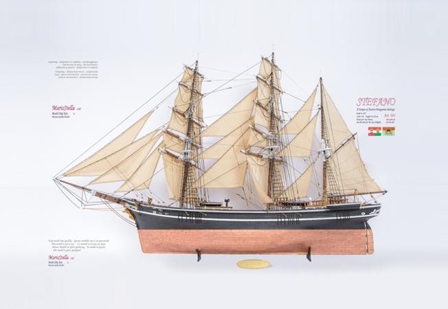
Oh, decisions decisions.... Well, I've settled on my next build. Barque Stefano by MarisStella. I've been admiring this model for a while now, and with Ethalion drawing to a close, it was time to work out what next. I hope Zoran won't mind me putting up one of the photos of his fine kit here.... So. I'll need to finish Ethalion first (for the space at my build desk if nothing else...), but then I shall be starting a new build log. And I'd just like to say thank you to Zoran and HeronGuy for being more than helpful with the questions I asked. I'm sure there will be many more as I proceed. Now... back to those ratlines!
-
Hi, Hope you don't mind me following along. Flying Fish is certainly a handsome subject. Looks like you've made a solid start. You'll find plenty of encouragement on this site. Rob
- 602 replies
-
- 1
-
-
- Flying Fish
- Model Shipways
- (and 2 more)
-
Congratulations! She's turned out really nicely. Thanks for sharing the build here. Have you decided what you'll build next?
- 39 replies
-
- 1
-
-
- billing boats
- danmark
- (and 1 more)
-
Thanks I've had to redo bits a few times, but it's getting to the stage I'm happy with.
-
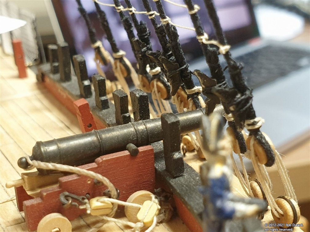
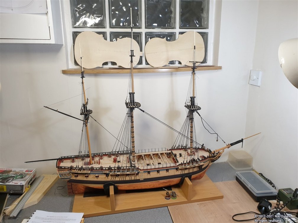
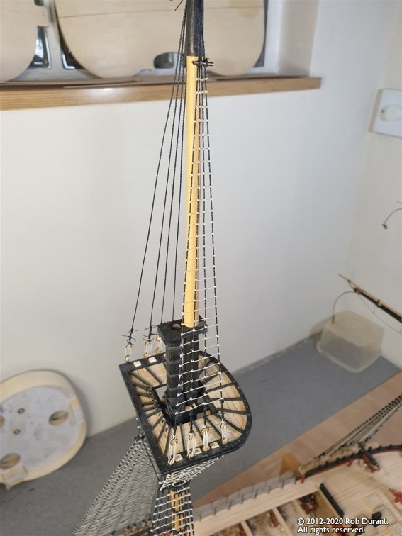
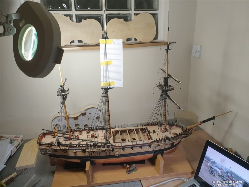
Hi all, Well, it's been almost two months since I posted, so here's a little post to show I haven't given up on Ethalion or simply disappeared. That said, I haven't been posting all the time firstly because I haven't got a huge amount done, and secondly because what I've done is a little on the repetitive side... But, here are a few pictures of progress. I've finished the futtock shrouds on the masts, and moved on to rigging the topmast shrouds and ratlines. I have a workspace that wraps round the wall, and I've found this invaluable with all the turning round of the model - this is not a ship that can be built in a tiny space! And that's without the boom on the mizzen! Thanks as always for the likes and encouragement, and I hope you're having a blessed advent-time! Rob
- 275 replies
-
- 11
-
-
Wow, you're making speedy progress. Great to see her nearing completion. She'll look very handsome on display. It looks like you're using foam as a stand while you work on her which seems very sensible. Does she come with a display stand?
- 39 replies
-
- 1
-
-
- billing boats
- danmark
- (and 1 more)
-
Here's a screenshot of the file size estimate in action... I've highlighted the estimate. It updates automatically whenever you slide the slider.