HOLIDAY DONATION DRIVE - SUPPORT MSW - DO YOUR PART TO KEEP THIS GREAT FORUM GOING! (Only 13 donations so far - C'mon guys!)
×


robdurant
-
Posts
842 -
Joined
-
Last visited
Content Type
Profiles
Forums
Gallery
Events
Everything posted by robdurant
-
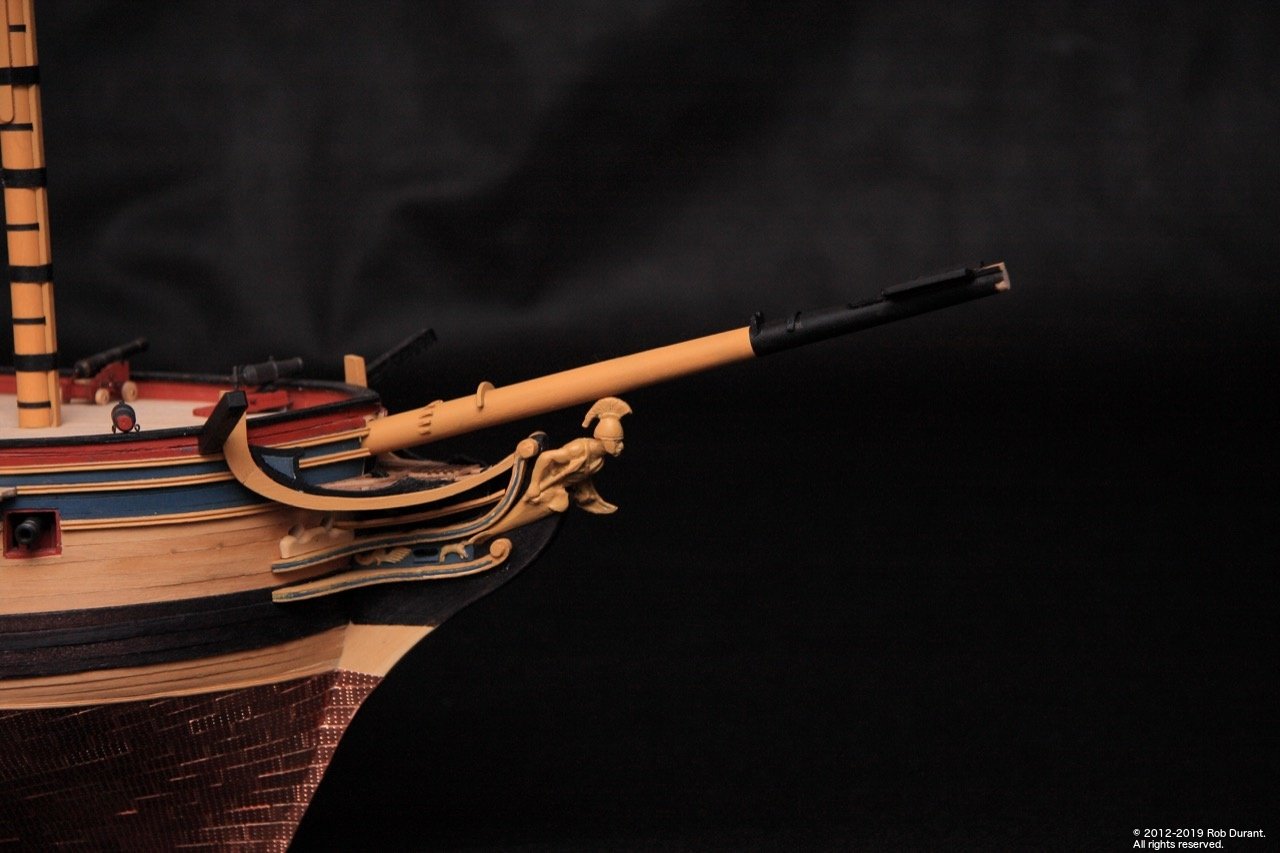
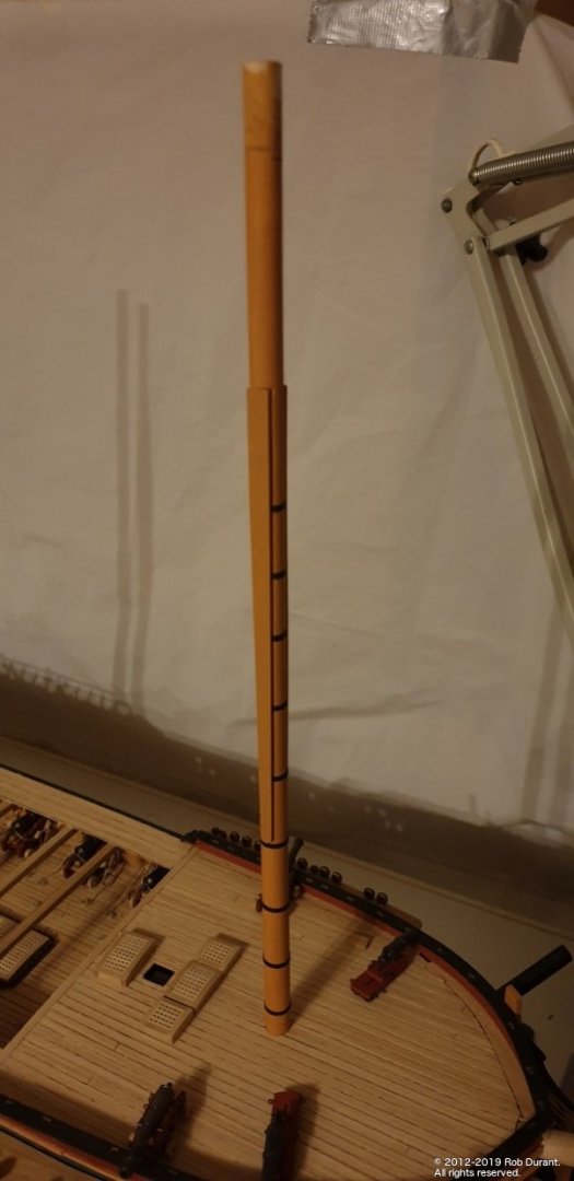
 A little more progress. I did a little more work on the bowsprit, and got some more paint on it. I was surprised how much I needed to sand, and paint, and sand and repaint the ramin dowel to get a good finish, but I think I'm getting there now. I slightly modified the layout at the outboard end to match the AOTS plans more closely. This included adding in a board in between the Caldercraft parts. Now I'm placing and removing the bowsprit continually, I'm so glad I put the hole for it right through the bow - it's so sturdy. I think I got this idea from Jason (Beef Wellington) - so thank you! A very worthwhile modification. I also did a little more work on the tops. The fore top now has the strip added, and the mizzen top is underway. I have a little bit of twist in the fore top, but I'm hoping I'll be able to pull that out gently when I put the shrouds and futtock shrouds on. It's not crazy, but enough to bug me! Happy building! Rob
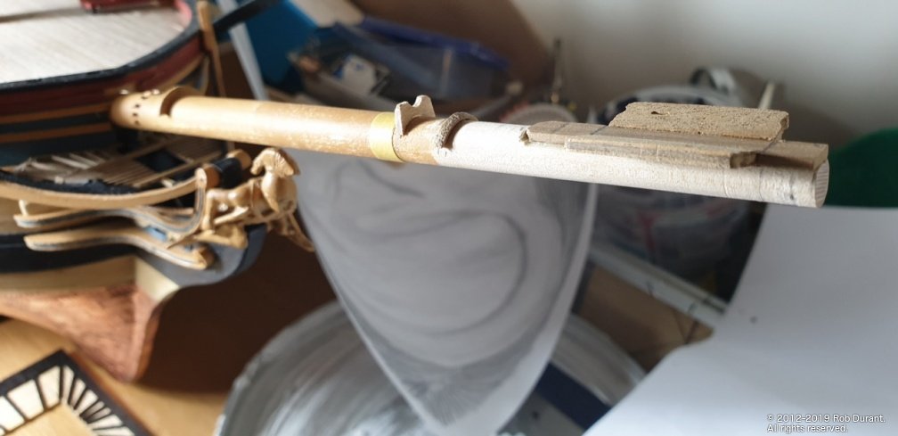
-
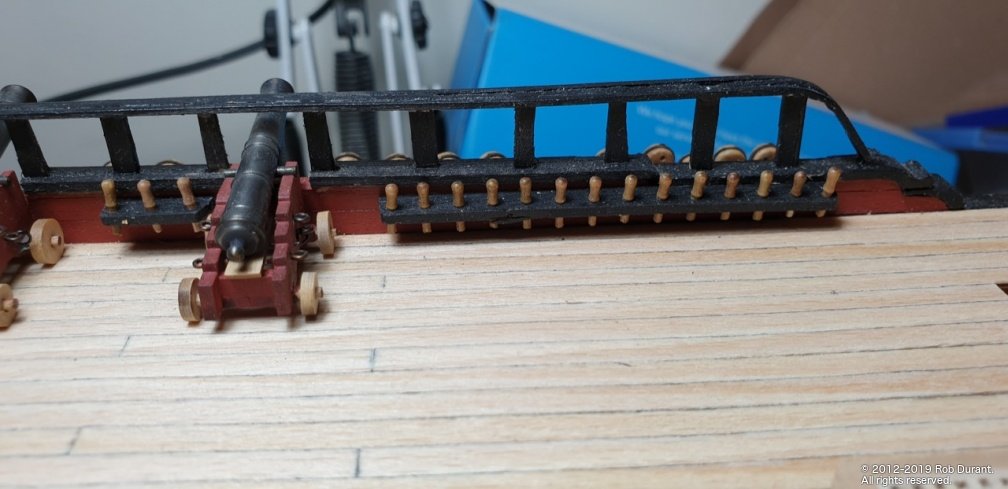
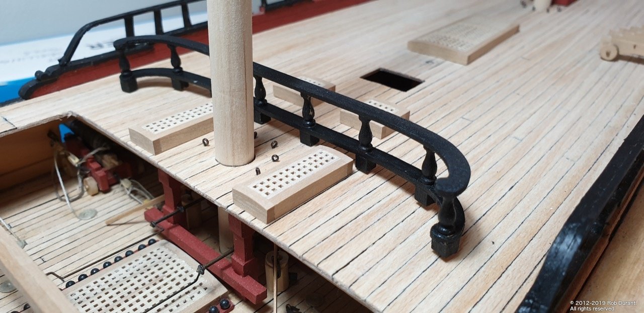
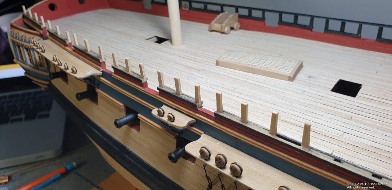
A little progress to report... I've got the pin rails on the quarter deck. I replaced the kit belaying pins with the newer ones Caldercraft do (purchased from Cornwall model boats). I came across these making HM Schooner Pickle, and to me they look far more the part. Because of the open quarter deck rails, these were shortened at the bottom so that they didn't touch the deck. Now that the pin rails are in place, I'll know where I can put the attachments for the carronades and guns, and the other fixings on the bulkheads. Happy building. Rob
- 275 replies
-
- 10
-

-
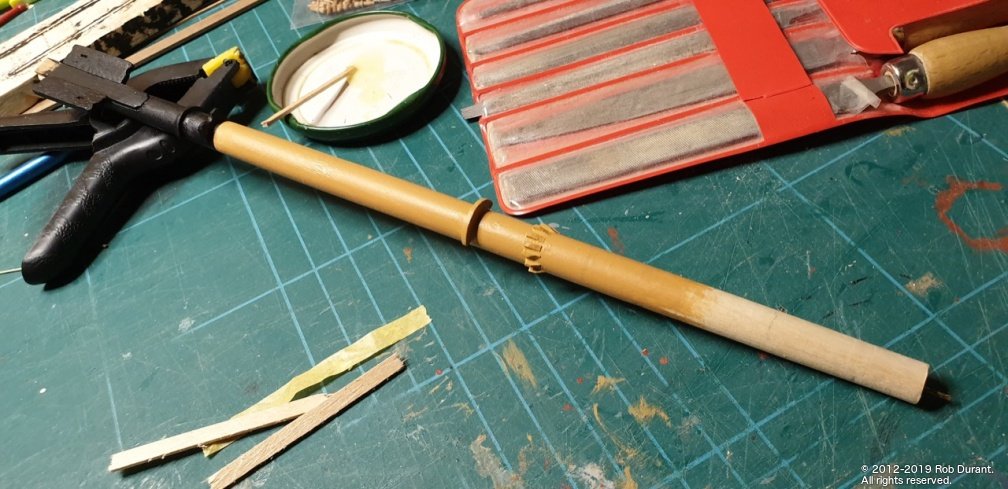
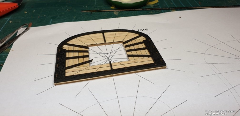
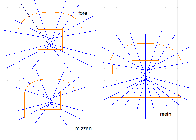
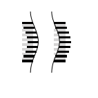
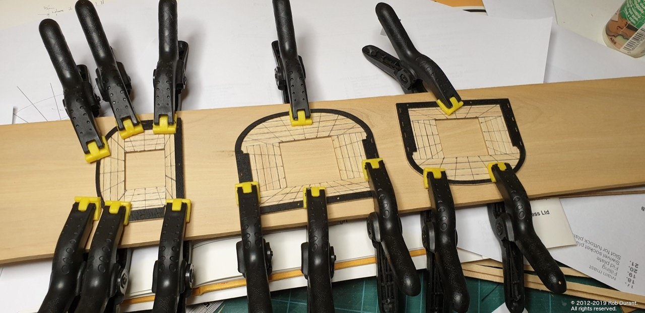
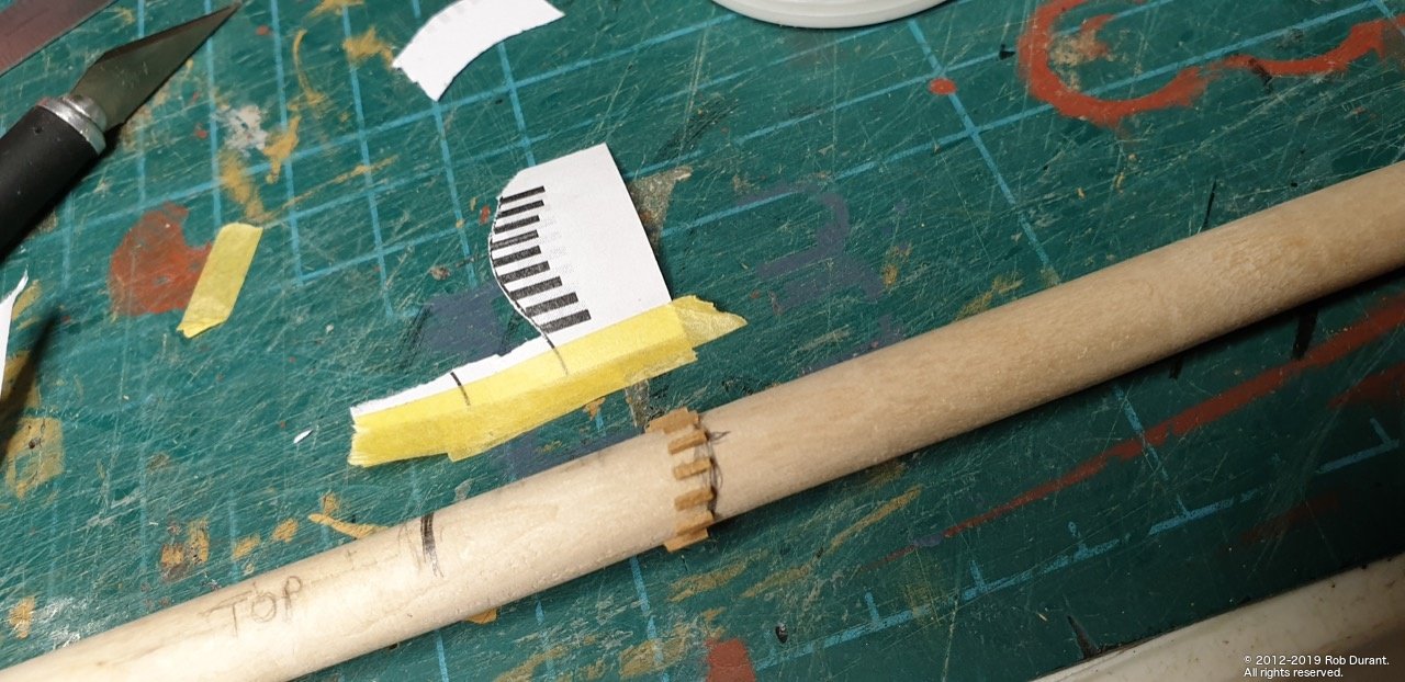
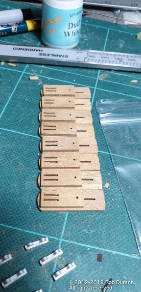
Hi all, Thanks for the likes. A little update as I work on the tops. I wanted to make sure the pattern of battens was correct on the tops, so looked at AOTS which only shows the outline of one of the tops. Looking at the Caldercraft plans they aren't symmetrical (and it's worth noting that the diagram of the tops in the manual is at a slightly different scale to the plans as well, which is a little confusing.) Anyway... here's my best estimate of what these might look like drawn out in CAD and exported as PDF (screenshot below, and the download link below that). Once the markings were drawn on, I glued the outer edge to the planking and clamped the tops down to try and prevent them from warping (which seems to be something of a losing battle at the moment! Tops.pdf Also, I decided to do a bit of work on the bowsprit. I worked out where the bits went on the bowsprit, and picked the bowsprit gammoning stops to do first... I created another template to allow me to line up the nine stops neatly, which is below. By my reckoning they need to cover 2/3 of the diameter of the bowsprit. It works out at 9x 1.2mm strip stops (I used 1mm), with 8x 1.2mm gaps in between. I marked the curve of the line of the stops on the bowsprit (further forward on top, further astern as they move further down the sides of the bowsprit. By cutting out the white space in-between the stops, I was able to fasten this round the bowsprit. BowspritGammoningStops.pdf Once the glue's properly dried, I shall sand these down so they taper in. Pretty pleased with how they went on, though. I think that's it for this evening
- 275 replies
-
- 10
-
-
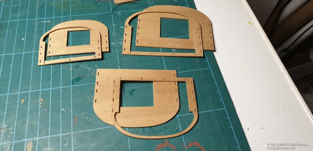
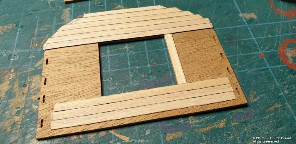
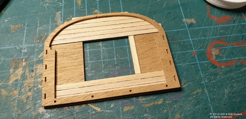
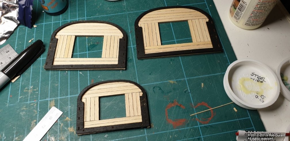
Hi all, More progress... just chipping away at various bits, really, while I summon the energy to finish off the bow. The tops make a nice mini-project. I didn't want to simply paint them all black, so I've used some of the remaining 0.5x4mm maple to plank them before putting on the diagonal strips. As it stands the black parts are just sat on top. I want to sand them down again and get another coat of black on before I stick them together. I'll probably mark the diagonals on before I glue them together as it will be easier to get a ruler onto the planks. Happily, these parts seem very close to the AOTS plans, so I didn't see any need to scratch build these (other than the planking). I'm really pleased with the contrast made between the maple and the black surround. Hopefully I shall have more progress to show soon. As always, happy building! Rob
- 275 replies
-
- 12
-
-
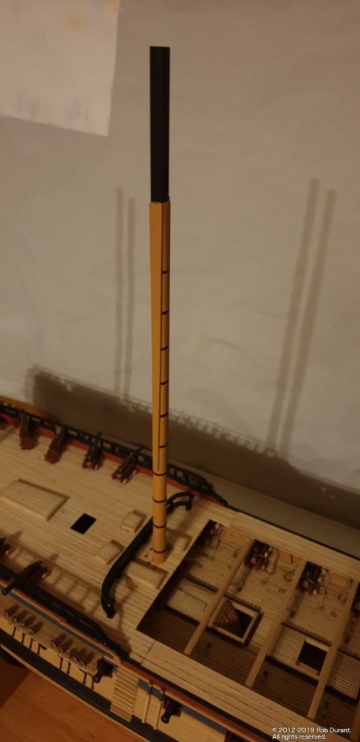
Thanks zappto More work on the masts: So far, so good - there are a few wooldings still needed on the foremast, and I've left the masts slightly long until I have the caps ready. Rob
- 275 replies
-
- 12
-
-
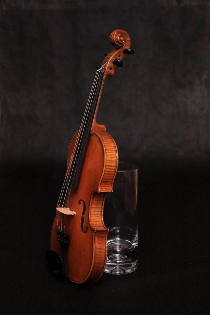
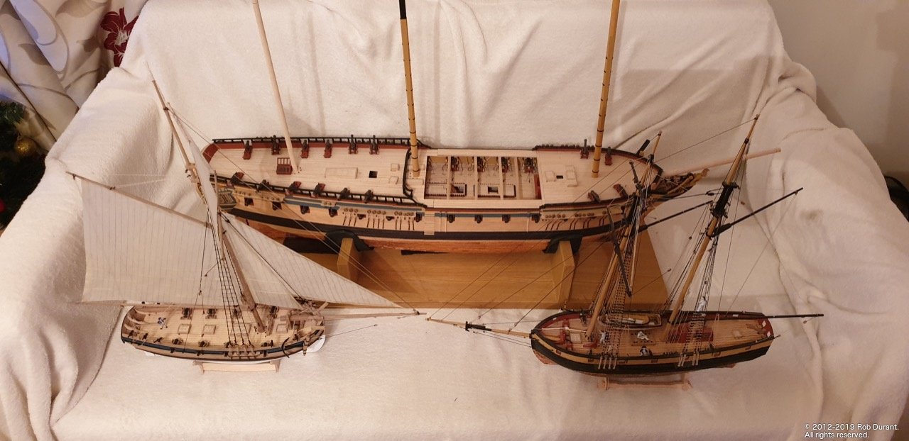
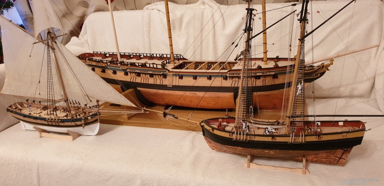
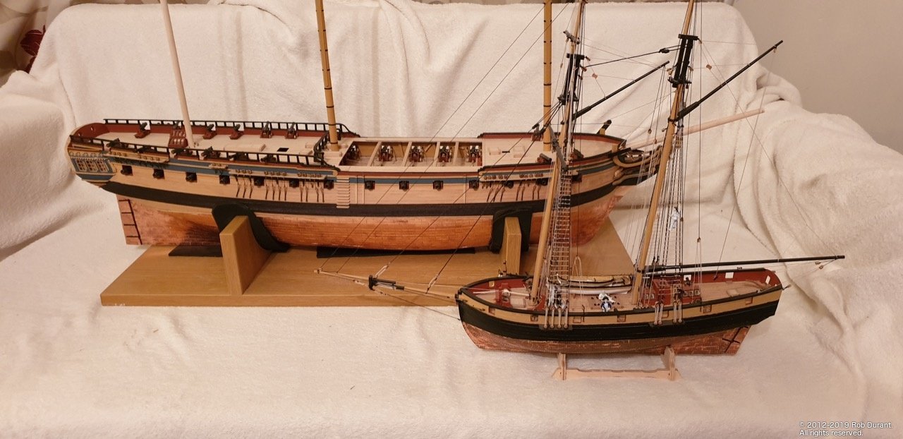
Thanks Vane, And thanks to everyone for the kind comments and encouragement. I completely agree with everything you've said and really enjoy photography myself. However, I think my problem this time was more an issue of laziness and lack of time... Below is a photo I took a couple of days ago, when I took the time to get the shot set up properly (and get out the right equipment) When I get a little more time, I shall get the models out and take some nicer photos... I was just grabbing the opportunity to catch them together while they were all out Interestingly, the background in the above shot is a kind of fabric... it's weed barrier from a local DIY store. Again, it shows what a difference lighting makes. Rob
-
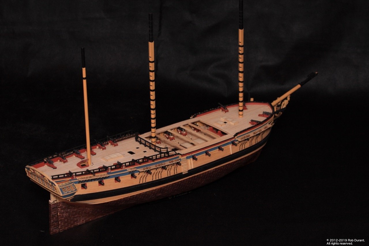
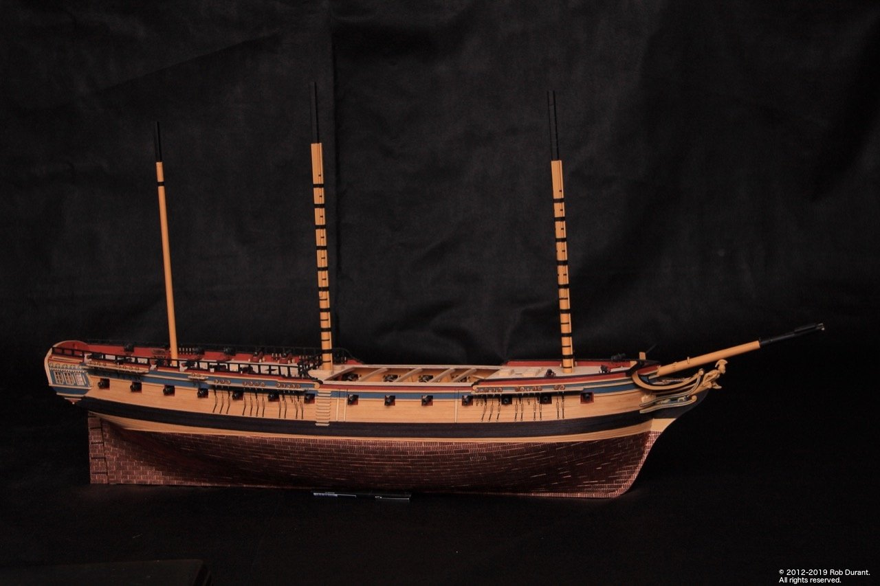
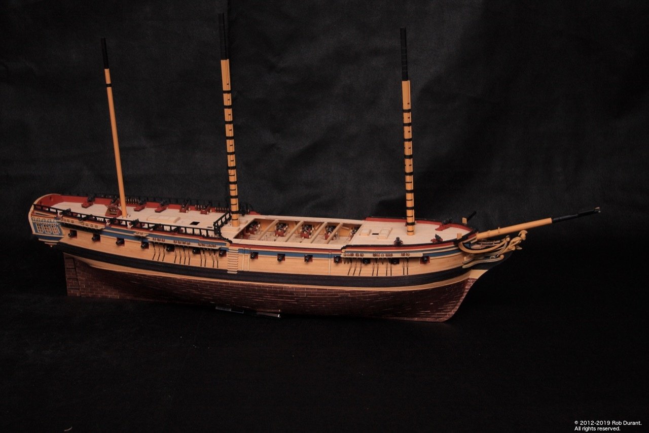
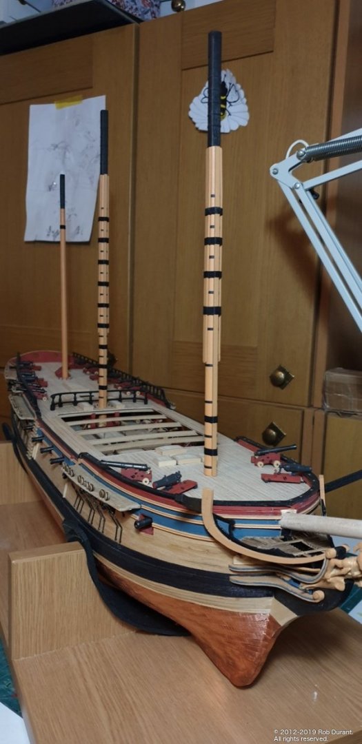
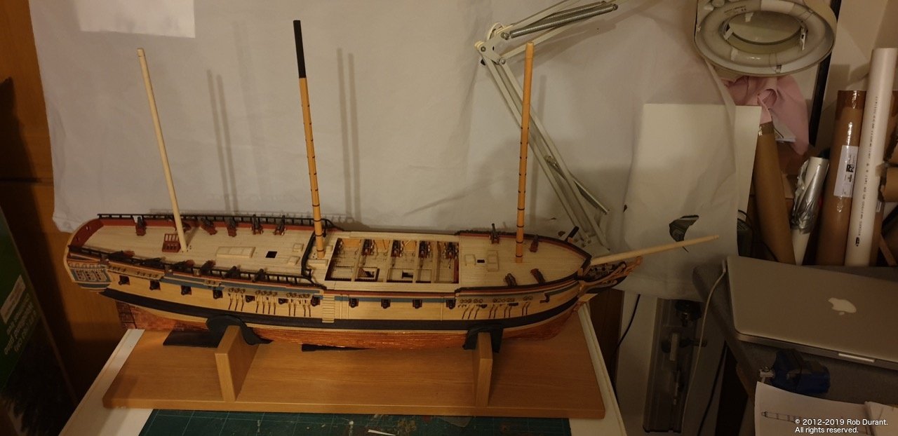
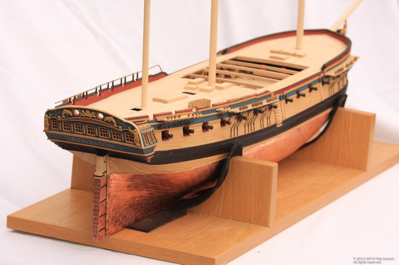
Definitely time for an update. Unfortunately I haven't been very well for a number of weeks so, quite rightly, work, family, etc... took priority, and almost nothing happened to Ethalion. Thankfully, I'm over the worst, so it's back on with the project. I needed a break from the things I'd been doing to get my head back into Ethalion, so I decided to start work on the masts. I've been itching to see what the lower fore, main, mizzen would look like and work out the colour scheme. Here is my first attempt. And finally, I've been moving my previous models into a new cabinet to display them, and it gave me the opportunity to get a few pictures of the fleet - all are Caldercraft - namely, the Schooner Pickle, and the cutter Sherbourne. Apologies for the quality of the photos... I'll try and get some better ones another time when I have more time, and more energy I was utterly shocked by the difference in weight between the smaller craft and Ethalion. I'll have to get some scales out at some point, but suffice it to say, it's significant! Next steps are to think seriously about the fittings needed for rigging on the quarterdeck (pintails, etc..); rigging the carronades and cannon, which are just loosely sat in position at the moment, and then whatever takes my fancy next Happy building Rob
- 275 replies
-
- 10
-
-
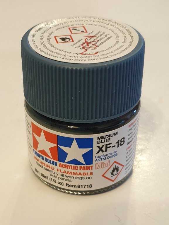
Hi Peter, The Blue that Jason (Beef Wellington) and I have been using is Tamiya XF-18 acrylic - "Medium Blue". i see what you mean about the transom in the second pic you posted but you seem to have it well in hand Rob
-
Not a new idea... In fact, Aristophanes did the thought experiment in his play Lysistrata around 411BC! ( https://en.wikipedia.org/wiki/Lysistrata ) I too wrestle with loving the craftsmanship and skill that went into making these "wooden walls", when held in tension with the idea of firing tonnes of metal and high explosive at fellow humans. Anyway - Yves, the model looks amazing. Looking forward to seeing those engine compartments come together. Thanks for putting so much effort into this fascinating build log. Rob
-
Hi Robert You may already have seen this but Caldercraft also make a metal primer which I believe etches into the metal a little to provide a more stable base layer. Don't know how effective it is on brass but I have had good results on the britannia metal castings. https://www.cornwallmodelboats.co.uk/acatalog/ap9205w.html Really enjoying following this build! Your willingness to go the extra mile is bringing some excellent results. Rob
- 527 replies
-
- 1
-
-
- caldercraft
- victory
- (and 1 more)
-
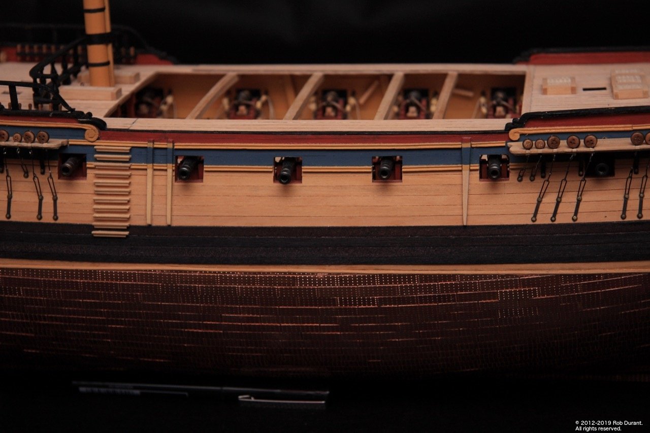
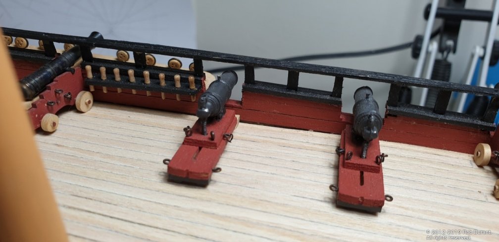
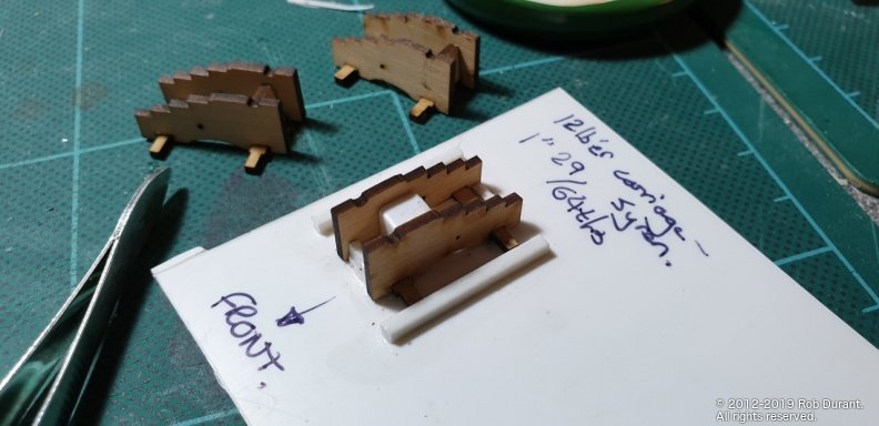
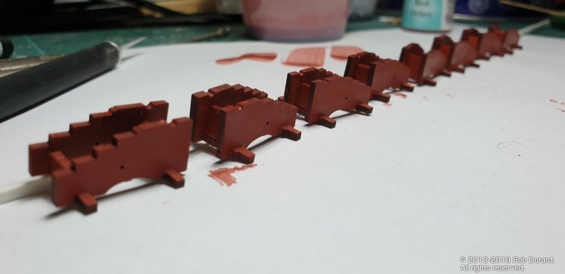
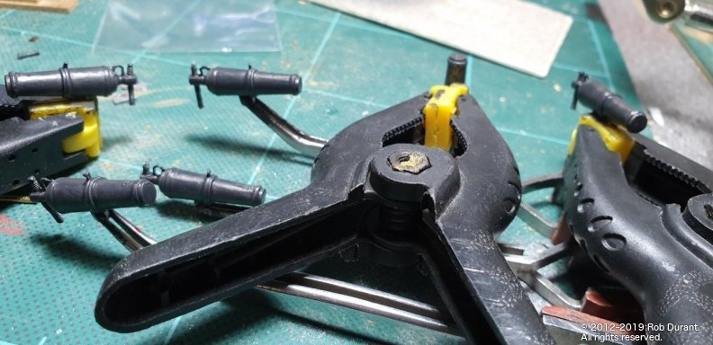
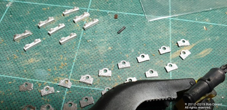
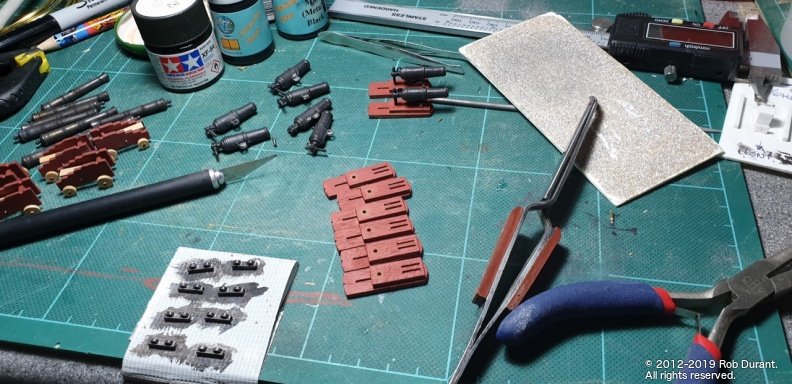
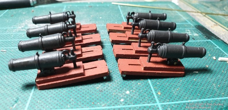
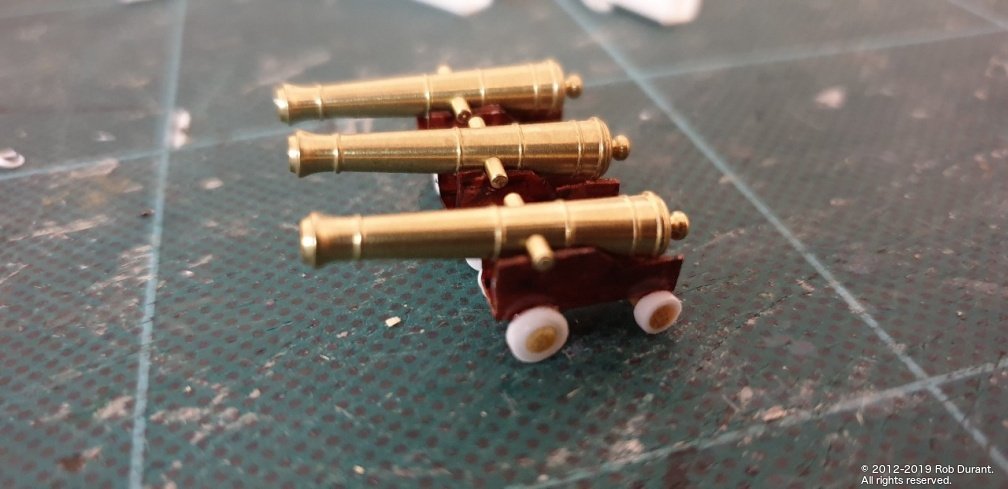
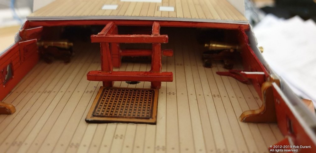
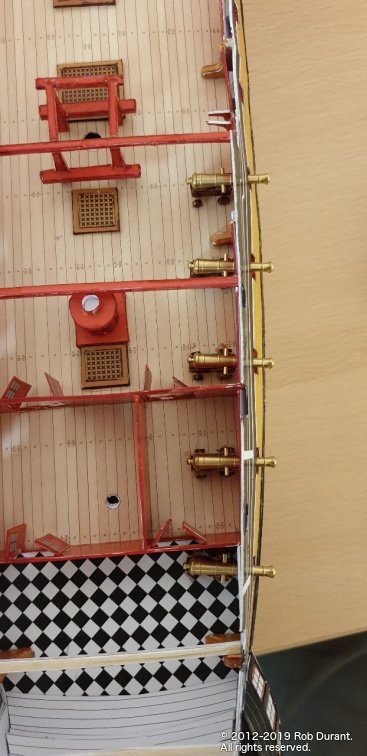
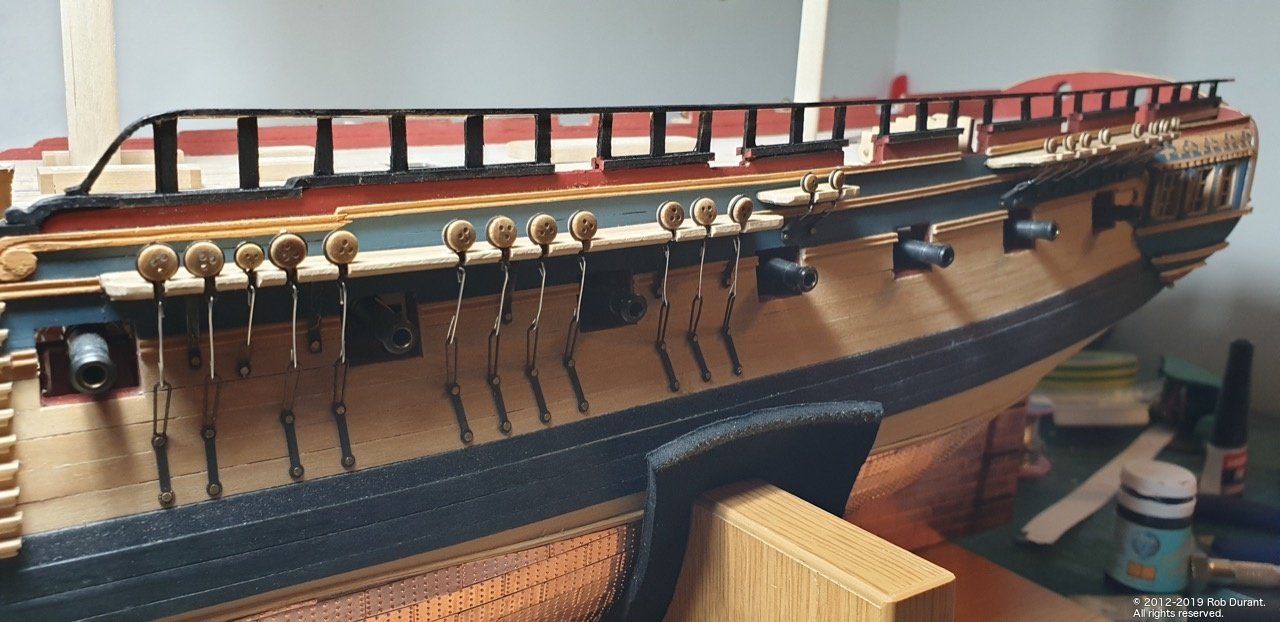
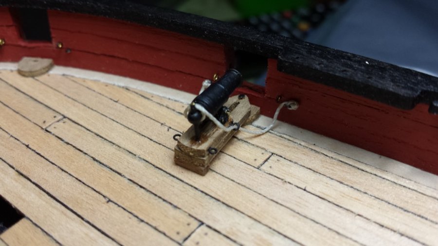
Time for a little update. The bulwarks are done, and I've been working on the quarterdeck armament... namely 12lb cannon (actually 9lb on the ship, but the carriages fit nicely) and 32lb carronades... The cannon are from Syren Model Ship Co. - these kits are fabulous, and I don't really do them justice! Step one for me is to build a framework around which to build the carriage. This helps me get them all square and neat. The following is a size comparison between the 12 and 18lb carriages... I hadn't appreciated what a difference it actually was. The wheels were sanded by attaching them to a rod and spinning them in sandpaper. Next up were the carronades, which are Caldercrafts from the kit. I was expecting to be disappointed with the castings, but they were pretty good, actually. Some playing around was required after cleaning up the castings to try and make the Britannia metal castings match the cannon barrels which were blackened, and I'm still not quite there, but getting closer I think. All the fittings were reasonably clean castings with minimal cleaning up necessary. Production line in full swing... And all this is just for the quarterdeck! Since this photo was taken I've also drilled out the holes for the eyelets, and added the brackets at the front. As other Diana builders have noted, the instructions suggest these ought to be mounted onto the sill of the gunport - however this practice was pretty much over by the time Diana was built, and instead the carronade was resting on a pad of wood on the deck beneath the port. This arrangement can be seen on Victory's carronades, as per the picture below, taken by Julian Fong: (https://www.flickr.com/photos/levork/2302412091) And even more clearly here: https://ageofsail.wordpress.com/2009/02/21/introducing-the-carronade/ , where the carronade has been swung up against the Bulwark, revealing the pad on which it sits.
-
I'd be surprised if it were to far out given that you have the lower deck in place... if you have a metre ruler and a set square you could check the keel for straightness and the frames that they're at 90 degrees to the keel, and then go along and mark the lines across the deck from each of the notches to the centre of the deck (at 90degrees to the centreline where you've made your cut) and see if they match up (that is to say it may be the deck that is mis-shaped) ... only a pencil, ruler, set square will give you the definitive answer. Once you know you can work out a plan of action. Definitely.worth working it out before.you go too much further though. Hope it proves to be a simple fix Rob
-
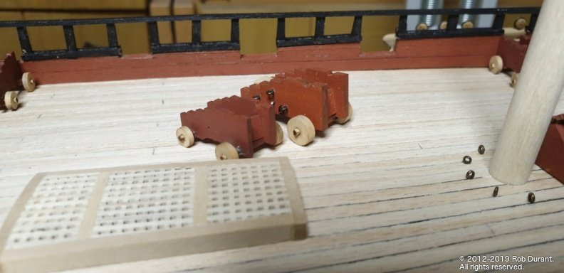
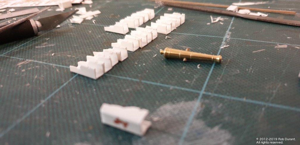
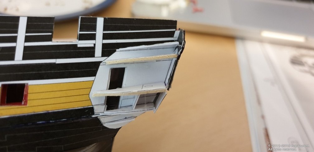
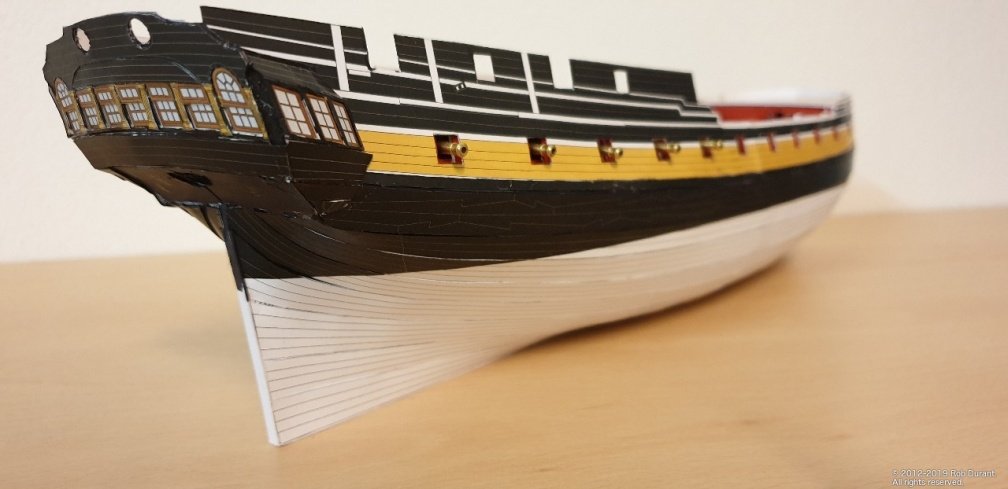
Well, another trip to Germany gave me some more time to work on Mercury. I'd been scratching my head about how to do the gun carriages. I ordered brass cannon, and when I tried to make the card carriages, they were both fiddly and not strong enough to hold the brass. It needed sorting, because at some point the fore and quarter decks need fixing down, and they'll make access to those gun positions impossible. I settled on using 5mm square plastic section. By taking one side off (the top) and shaping the sides, I was able to get an approximation of a gun carriage. It's by no means perfect, but this model is an experiment, and my first attempt, so I'm more interested in working my way through it than getting everything absolutely perfect. Anyway... coupled with cocktail stick axles and plastic tube cut down for the wheels, it looks something like a cannon with carriage. (The wheels are waiting to be coloured). I've left the cannon brass intentionally to see whether I like it. The answer is, I wouldn't do it again on another model, but it does add a bit of bling! I may yet remove them and paint them. They're a bit gaudy for my liking and don't seem to sit well with the rest of the model. I completed the "second planking", and added the quarter galleries and stern gallery. Where possible, I've tried to pre-colour the edges, but you can see where I haven't quite got the fit right, and the white has shown through. Something to bear in mind for anyone attempting a paper model that has large areas of black on it. I also neglected to build up the stern - I got over-excited and just stuck it all together, and then it was too late! Another lesson in measuring twice, cutting once! I think the depth of the stern would have looked much better, but there we go. That's how it is now... Something more like this, perhaps... The final task was bringing Mercury home from Germany... I carried it carefully padded with tissues in a box... and it survived (only two cannon broke free, and it's all so small they did no damage at all.) I wanted to get it home before I started adding too many external details to the hull, so perhaps there will be more regular updated from now on. We'll see! We're getting towards the fine detail part of the build now, so I'll need a new blade in the craft knife. As a footnote, I answered my own question from above by re-reading the instructions from the model.. the thicknesses specified are of the card to which the paper part should be stuck. Thus where it says 0.5mm, the final thickness will be 0.5mm + the thickness of the original part. Perhaps that will help someone out down the road. Happy building Rob
-
Thanks Jason Yes it's another challenge along the way. I've been able to place plank nippers in between the sideways planks to gently curve the whole lengthwise... seemed to work okay although the experiment did mean that it's now proving harder to complete the piece as it isn't flat. Something makes me think I should have seen that coming! 😂 🙄
-
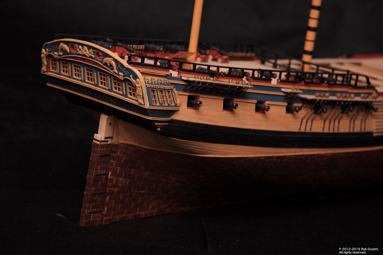
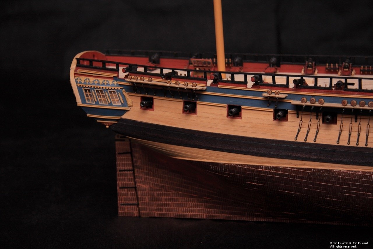
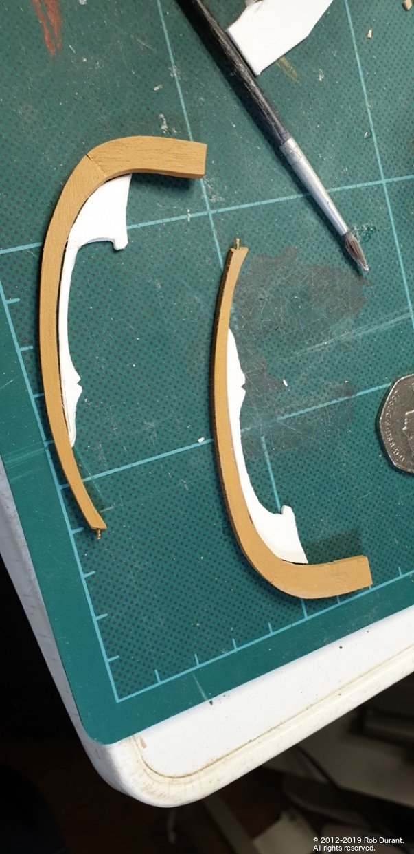
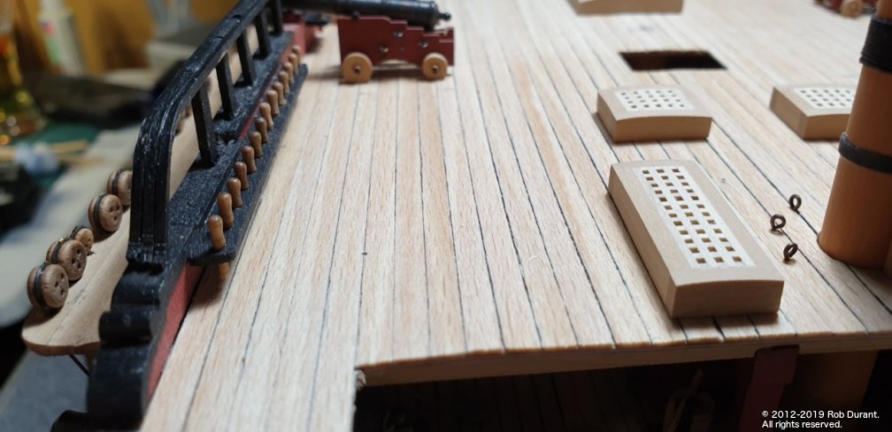
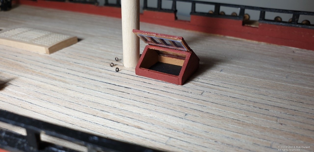
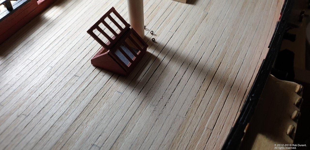
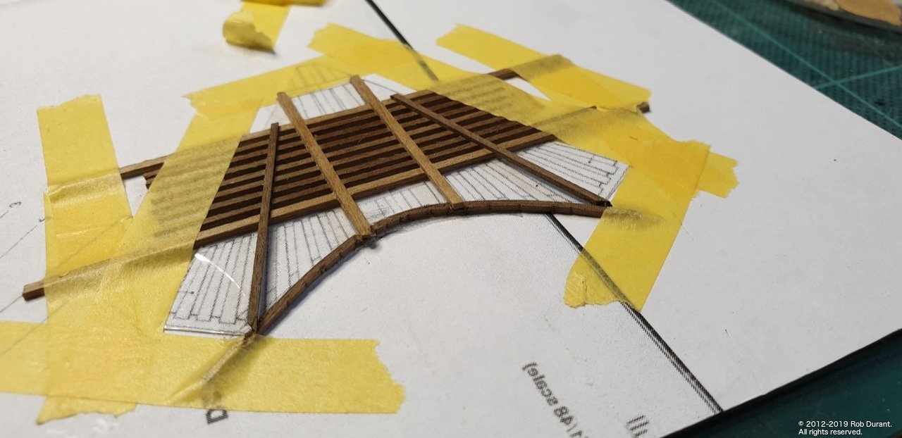
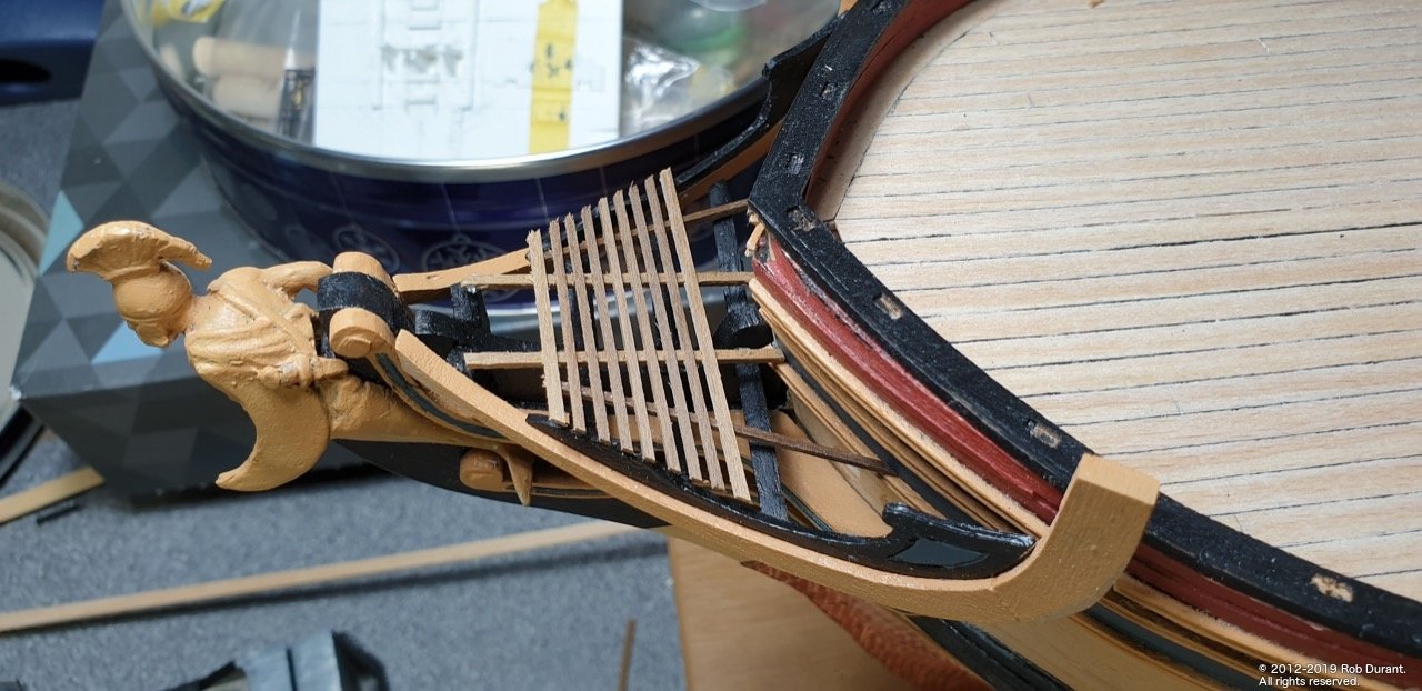
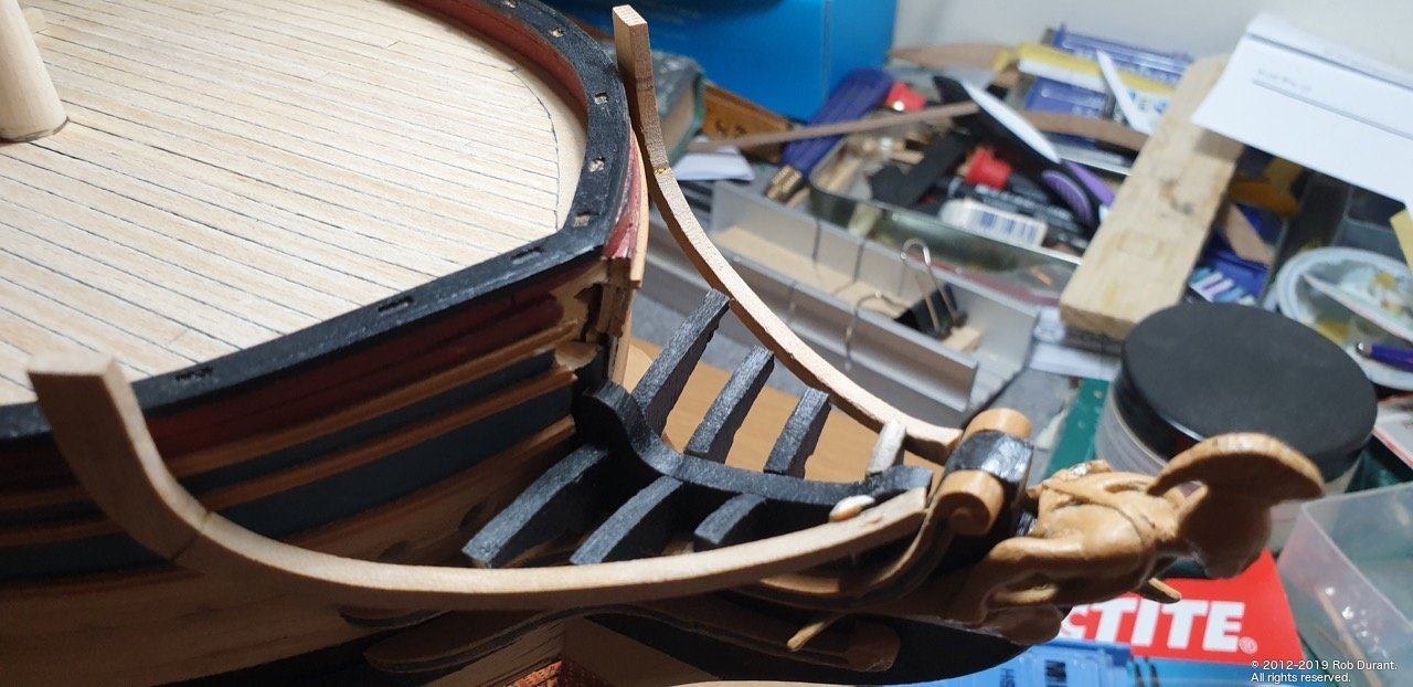
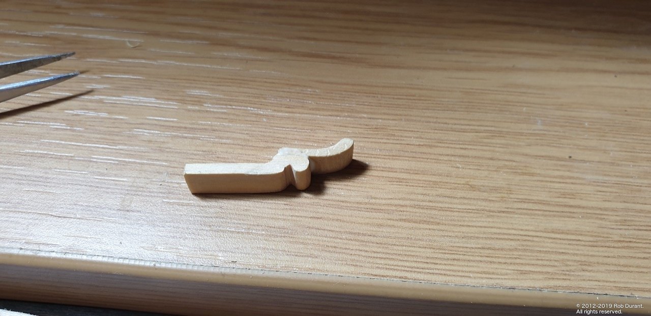
Another little update. More work on the beakhead railings... I've used plasticard, which I later engraved using a proxxon engraving bit to add the inset. This can be seen in the last photo of this post, with the first coat of paint on it. Hopefully this will provide a little dignity / privacy for those using the rear-most seats of ease! Some deck furniture... (the hatch was made form scratch, as the kit one ended up too wide, and looked a little clunky to my eyes. I haven't decided whether I like this open or not - the captain may prefer if it's shut so he can't be overheard discussing his orders by the whole ship's company, but if I leave it open I'll add a couple of rods to represent supports. I don't need to decide now anyway. In the bottom I put a square of card, which provides a little depth, but means I don't have to make the deck opening any bigger (somewhat tricky at this stage!). The balustrades aren't glued on at the moment, as I'm sure there will be all sorts of things that will be easier to do without them in place... the positioning holes are drilled, however. And the beginnings of the gratings that the seats of ease sit on. The shape is quite different from the kit shape, because of all the reworks I've done, so I've begun building this shape from scratch using the AOTS diagram as a template. I'm building them upside down. I've started cutting it down, but left it slightly oversize, so I can fit it closely once it's somewhat more complete. I also want to curve it as I go... Hmm... we'll see how that turns out! It's made out of 1x1mm and 1x2mm walnut strip, so I will need to paint it.

-
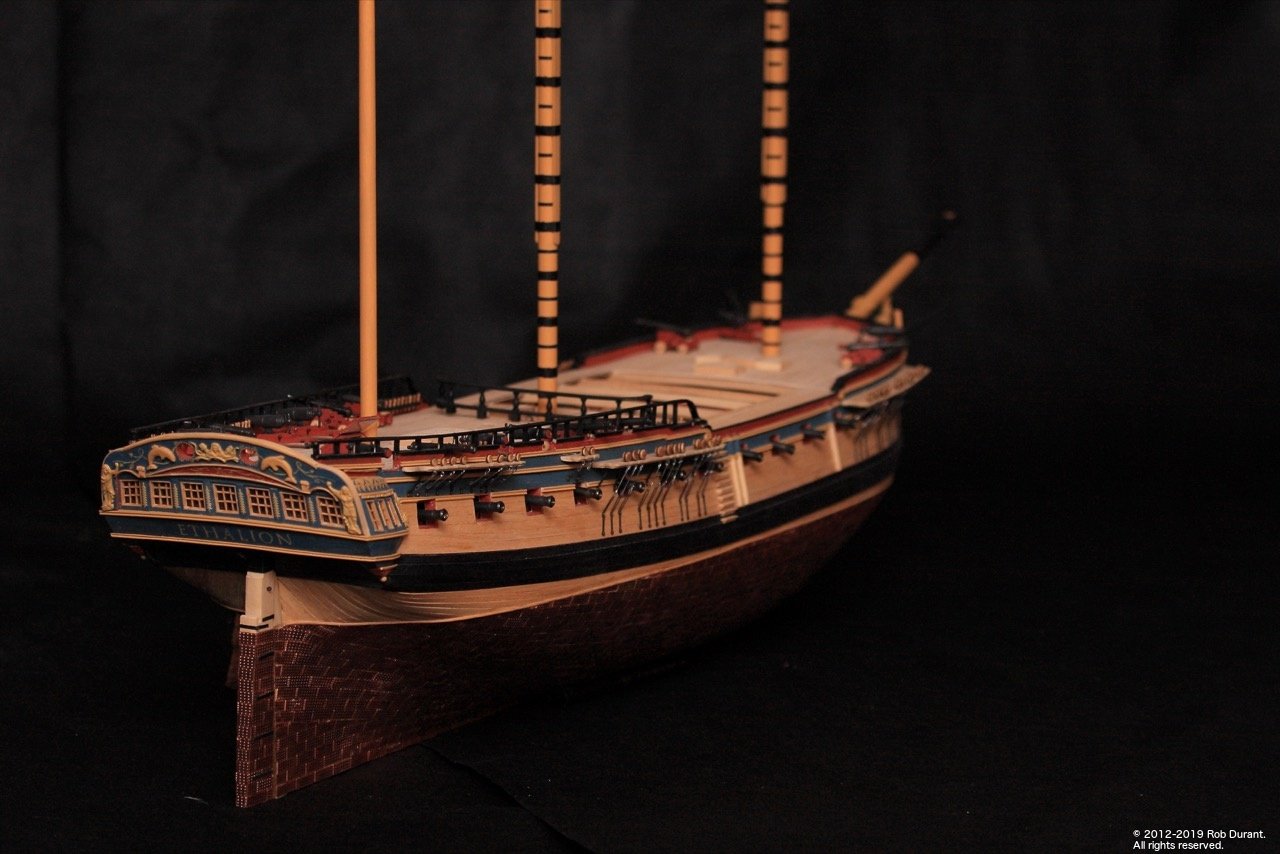
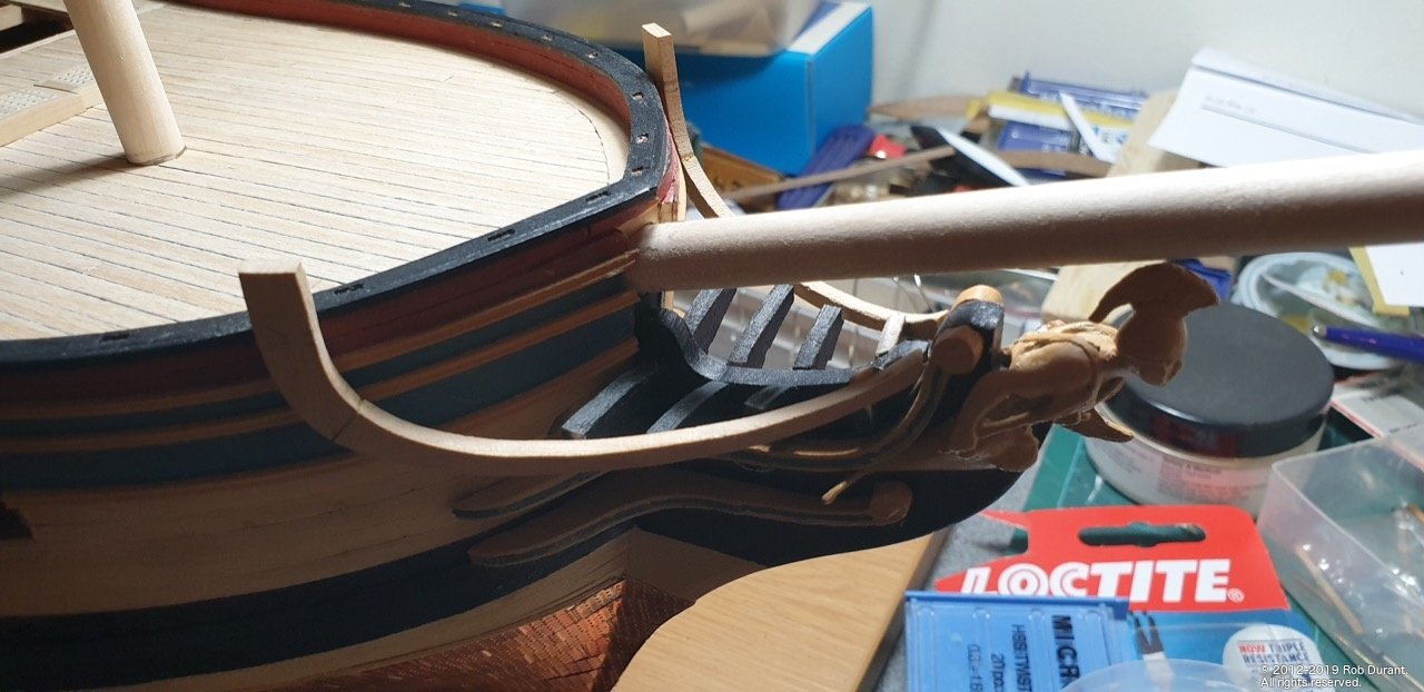
More progress on the railings and the bow over the past few days. A bit more work to do yet... but progress all-the-same. It is helpful working on one end of the boat while glue sets at the other! I need to weigh Ethalion at some point to find out just how heavy it's got.
-
Thanks for all the likes, kind comments, and encouragement. A mini-update to end the day... The railings have had their first coat of paint... This angle seems to show every slight imperfection, but they look much better in real life
- 275 replies
-
- 10
-
-
Thanks Eamonn. It's a great subject to model and I'm really pleased with how it's gone so far the top photo is taken with my SLR camera which definitely does a nicer job than the mobile at catching the colours.
-
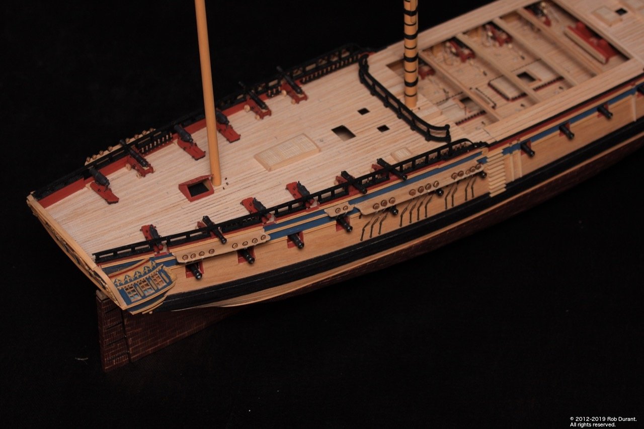
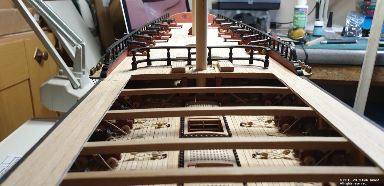
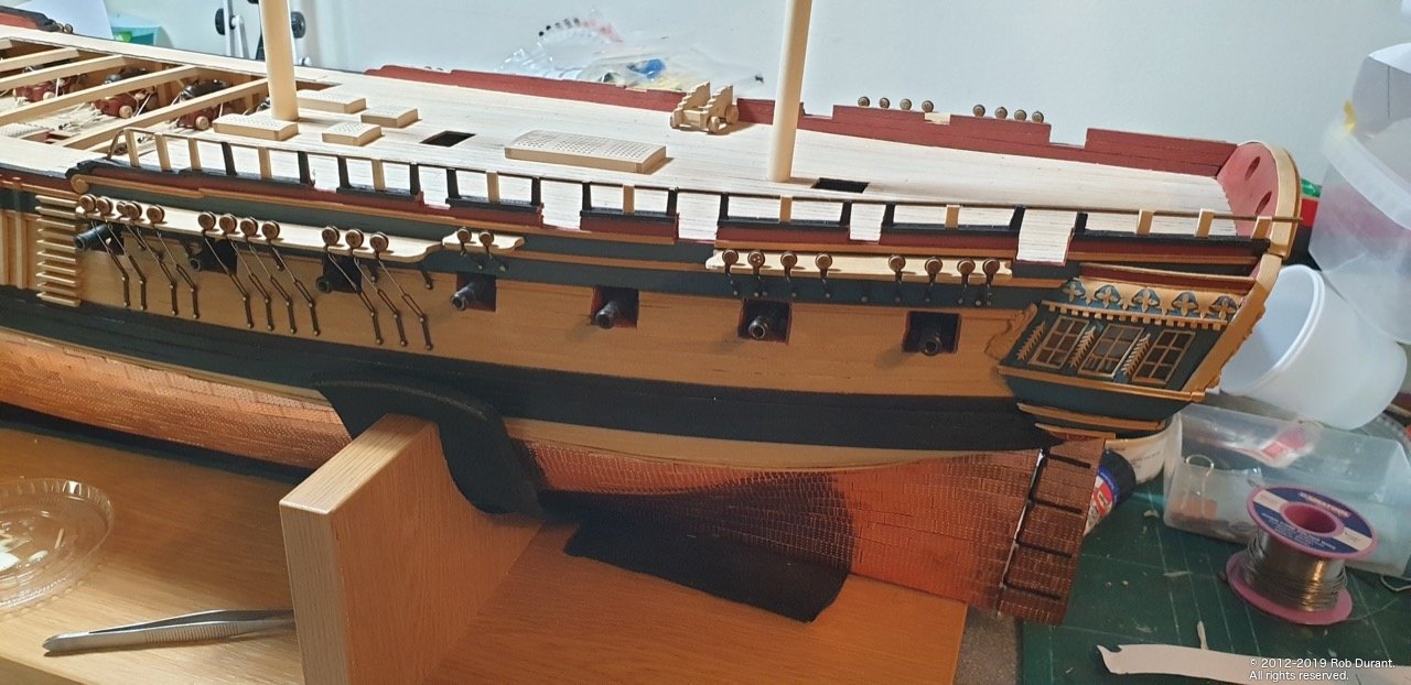
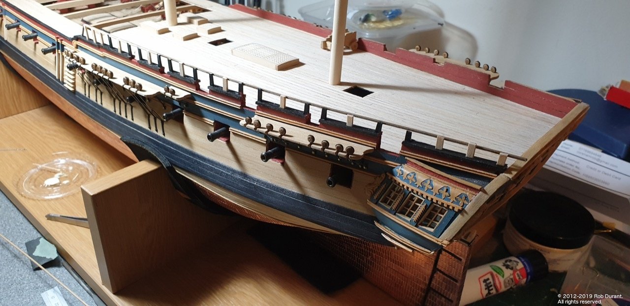
A small update... the port channels all have their deadeyes and chainplates attached. I need to fill the gaps in the channels and smooth them back, but it's nice to have this done. I've also been working a little more on the open rails on the quarterdeck. I've started filling in the central row of the top railing with 1x1mm walnut, and then I'll put the rail on the outside edge to complete. A 1mm brass wire was added at the bow end to straighten up the rail. It should be virtually invisible once complete, but should add strength too, for when (not if) I knock it! Happy building Rob
- 275 replies
-
- 16
-
-
Because of the tiny size of these carronades you may decide to simplify... normally you have two things going on... 1. A thicker rope that goes round the back of the gun and fixss to either side of the gunport. This is to contain the recoil. 2. thinner rope used to haul it out ready to fire. 3. Also on the pic in the last post you can see another set used to point the carronade. (Training tackle) On my model I decided just to put the breech rope... But this is where each of our models ends up unique... regardless of what you choose I'd recommend making up a template for where the holes will go on the hull and drilling them out using that so they all end up uniform. It maybe worth trying one off the model in a card mockup to see if your plan will work. Finally as you drill the holes watch out they don't pop out on the other side Rob
-
Hi Peter, I haven't put any finish on the parts that will remain unpainted, as I didn't want to find I'd put a finish on and then couldn't attach other parts (steps etc..) to the outer hull, but at various stages as I've worked, I've used paper and masking tape to protect it as I work on other parts - especially when I've been painting things. I'm still in two minds about how to finish it. In the past, I just haven't used anything, but I think I'd like to do something this time. The wipe-on poly that seems to be so popular in the states seems harder to get hold of over here in the UK, and I'm wary of using oil in case the surface ends up sticky and attracting everything in sight... some testing will be required, I think. Great start on the copper plating It goes pretty quickly once you get in the groove... Rob
-
Hi mugje, I expect solid walnut at that sort of size would have been too fragile as it would split along the grain... plywood walnut is a better material for the task, but it does bring with it the challenge of tidying it.up to look neat. The alternative would be a harder finer grained wood such as european boxwood, but it's very expensive compared to walnut. Well done with those carronades! They look fantastic... much neater than my effort... Pickle was my first wooden model too. Keep up the great work. Rob