HOLIDAY DONATION DRIVE - SUPPORT MSW - DO YOUR PART TO KEEP THIS GREAT FORUM GOING!
×


robdurant
-
Posts
842 -
Joined
-
Last visited
Content Type
Profiles
Forums
Gallery
Events
Everything posted by robdurant
-
 Almost the same in English... https://www.dictionary.com/browse/lath Love these lesser used words... they make our languages rich and interesting. Back to the ship and she's looking terrific. I built a deans kit 20-something years ago and struggled with the printed styrene... the printing didn't seem to be quite accurate (or it may just have been lack of skill on my part)... You're doing an amazing job though. The view along the superstructure is amazing and looks absolutely true... impressive for a structure that long and thin. Keep up the good work! Rob
- 446 replies
-
- 4
-

-
- zebulon b vance
- deans marine
- (and 3 more)
-
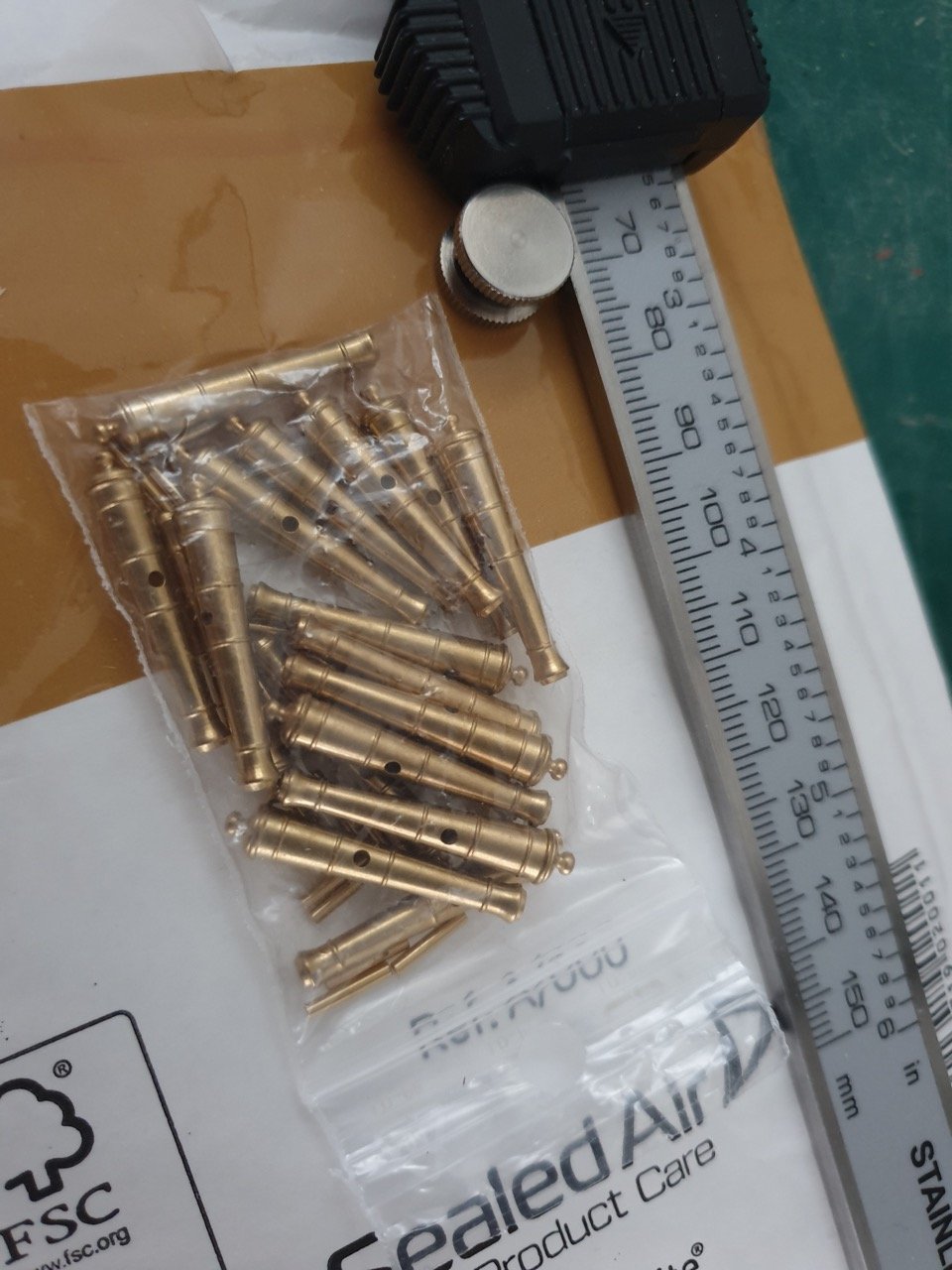
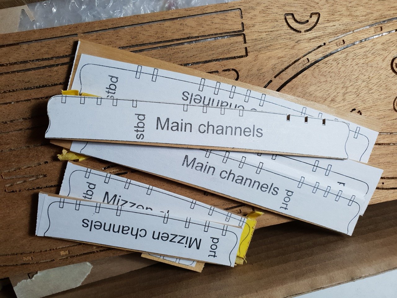
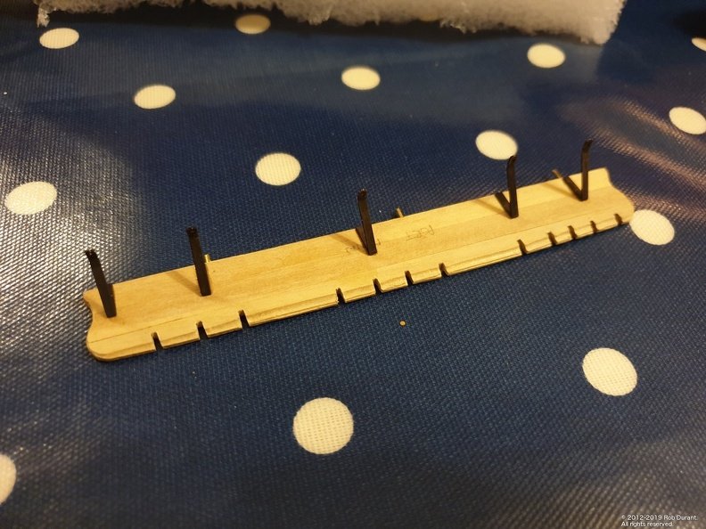
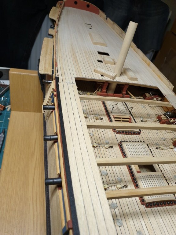
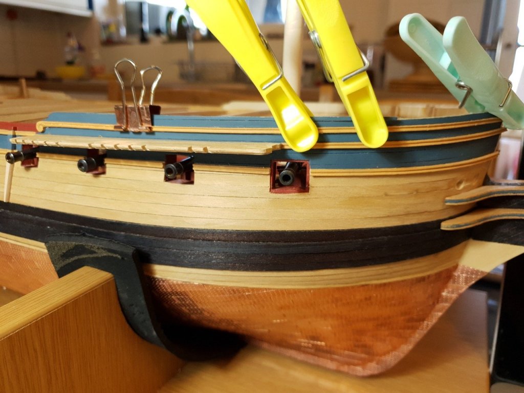
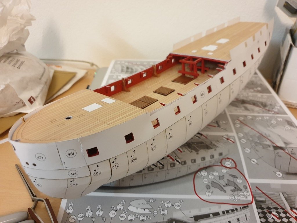
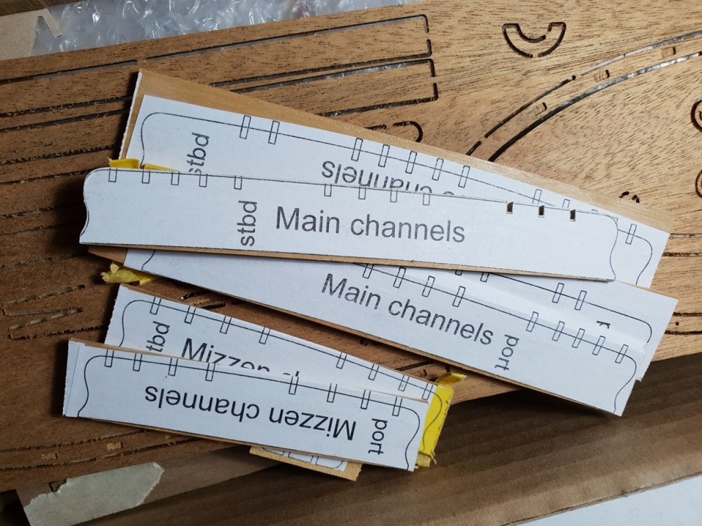
Hi all, A short update. I've completed planking the forecastle, gangways and quarterdeck. The next task was to plank the bulkheads, which were pre-painted red ochre. These could have been yellow ochre, but I figure light levels aren't an issue on an open deck, and I like the contrast. I planked the bulwarks on the quarterdeck, which was simple enough, but when I reached the foc'sle I realised that I'd cut down the hull too far. A good while has been spent building this up again so that the sheer rails look right next to the rail at the top. I think I'm nearly there, but it's tedious, fiddly and time-consuming... I'd work harder to avoid this in the future. Thankfully it's on an area of the hull that's painted. To break the tedium I decided to add the channel supports. As others have noted, there are 22 supplied, and _at least_ 26 are required according to the Caldercraft planks. I reused some of the rudder hinges (which I'd replaced with black card because they seemed too bulky for that) for this purpose. Even then, I reduced the six supports on the main channel to five so there were enough to go round. (One could buy another set of the Diana photo-etch, but at £95 it's a bit steep for 6 channel support brackets! The brackets were blackened first. The channels themselves aren't glued onto the hull yet, so they were removed and the brackets stuck to the bottoms, then the channels temporarily reinstalled. These will need gluing on soon, and once glued on, then I'll drill the holes to pin the brackets to the hull sides. (After a good sleep, and when I'm feeling confident I won't leave the hull looking like a swiss cheese!) I'm very pleased with the results so far. All comments welcome, and all likes appreciated. Rob
- 275 replies
-
- 17
-
-
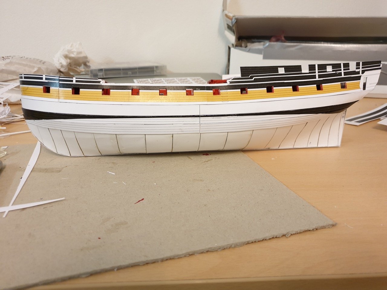
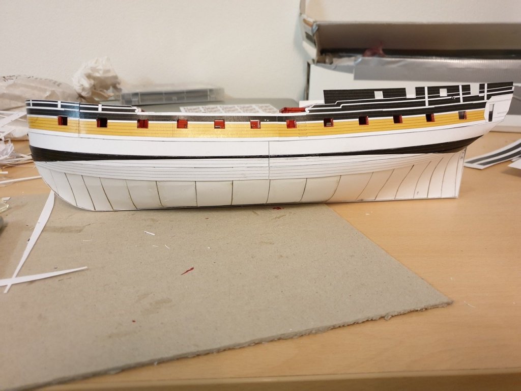
Well, the quarterdeck is planked and the starboard gangway. I've also managed to tidy up the edge of the deck where it meets the hull side at the waist. Really pleased with how that worked out. Not sure whether it needs a yellow ochre trim... I can add that later if I want to. The gangway planking is wider than the quarter deck planking, as per AOTS. On the bottom photo you can see a box strip laid tranversely in front of the gangway planking - I'm still not sure whether I like this effect. I may revert to a narrower maple strip to match the rest of the planking as the contrast is too great. Something needs to go across the deck there, though. Happy building Rob
- 275 replies
-
- 13
-
-
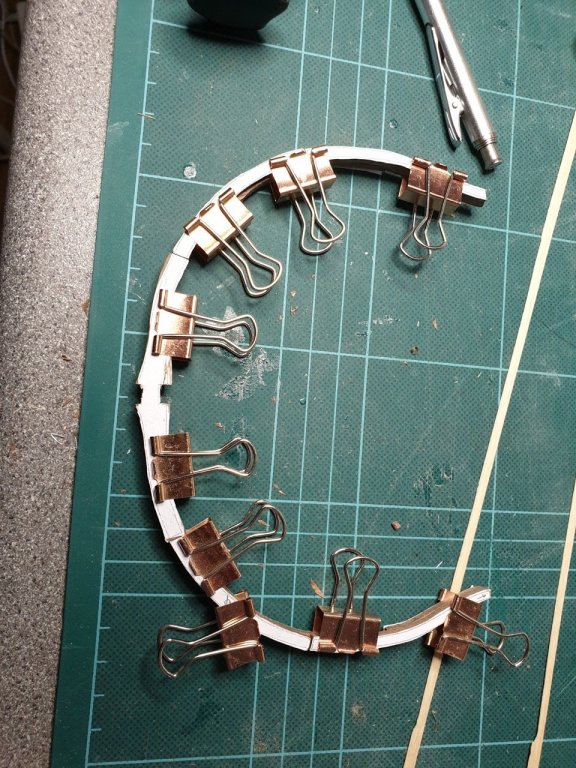
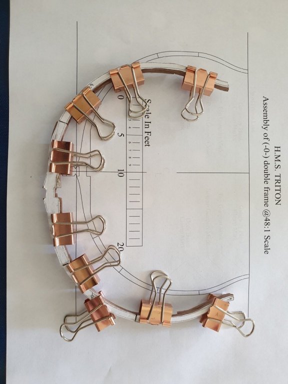
Well, somehow 2 1/2 years have flown by since I last did any work on this... so long in fact that when I came back to have another crack at it, I realised to my horror I'd thrown out the original parts! That said, the process of remaking them today has been educational and I've made some real headway. I realised that I'd been approaching the build by trying to crack a nut with a sledge hammer... This time, rather than trying to sand down the frame parts, I gently carved away the excess with a nice sharp xacto blade.. The walnut was lovely and soft and as long as I approached inside curves from both directions and took it steady, it was surprisingly quick to get a whole frame made. It's by no means perfect, and I'm expecting to remake this frame when I've made some more... but it's certainly teaching me lots. So... here are the pictures of my first full doubled up frame. It's the dead centre frame. I tacked it to the keel with a little carpenters glue to see how it looked and even the process of doing that made me realise quite how fragile this is going to be when i assemble it until I get the horizontals in.


-
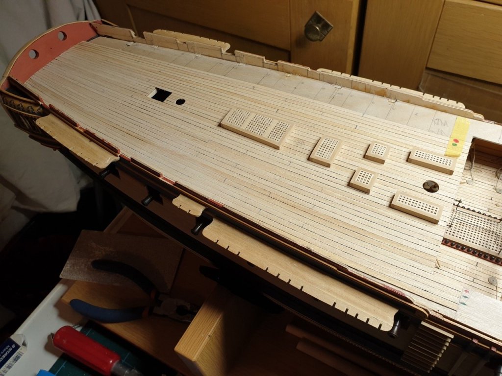
As I'm uploading the photos to my gallery, a brief update on how the planking on the quarter deck is going... It's been a learning curve, but for a first attempt I'm quite happy so far. The curve gets some way towards matching the shape of the quarter deck, but not all the way there. In the future, I think I'd spend a bit more time building a jig and really getting the planks the right width straight out. That said, the idea of shaping the planks all together seemed to work fairly well. They were shaped in one length, and then each had the joins marked on. That avoided the need to shape each individual plank separately, and led to nice sharp lines for each run. The joins were cut and edged with black sharpie before being stuck down. The first plank laid at the centre line was marked on both sides, and each plank laid after that was only "caulked" on the outside in the hope that the join would be somewhat less bold. Carpenters glue (Aliphatic resin, or PVA on speed, as I prefer to call it) was used throughout. It allows time to reposition, wipes off easily when it oozes out, doesn't cause me breathing problems, and grabs quickly enough that I don't go mad waiting for it to set... it also sets hard enough that I can trust it not to let go at inconvenient moments... Here's are a couple of photos... The gratings are just laid out roughly in place, and I have yet to complete the outside run on the starboard side and five or six runs on the port side... but it gives some idea of the overall effect. In retrospect, I'd provide more support down the outside edges of the false deck if I were doing this again... it has a bit of flex, and as I added the starboard planking, I inadvertently pushed it down a bit, leading to a wavy edge for five centimetres or so around the rear channel area... It's only a couple of mm up and down, but it's going to irritate me. That said, it'd be a nasty job to lift it all now, and my attempt to pull the deck up was a dead end - I was going to make a terrible mess of things, so I'm going to have to live with it. Once you're a cm or so away from the edge, it's all even again... Hopefully it'll be less evident once the bulwark is planked on the inside... (hopefully!), especially once the guns are in place, and the standing rigging takes the attention away. Also, a little support right at the rear of the false deck on each side would have been a sensible addition. Lesson learned - and I'll be older and hopefully wiser next time! On the plus side, the extra hole where I'd moved the mizzen has been covered up - that was a nice milestone. I've marked in pencil where the capstan should go, but I'm not going to bother putting a hole in the deck - who'd know?!? The mast stubs fit beautifully which was a huge sigh of relief! Happy building! Rob

- 275 replies
-
- 11
-
-
Hi Christian, It may have been a straightforward approach, but your Diana looks absolutely amazing - I've been back many times to look at the build photos and see how you've done things to help me along the way, so thank you! I particularly like the white columns between the windows on your build - they look really good! It's great the way we set out with the same kit but end up with unique models - each a reflection of its maker. Rob
-
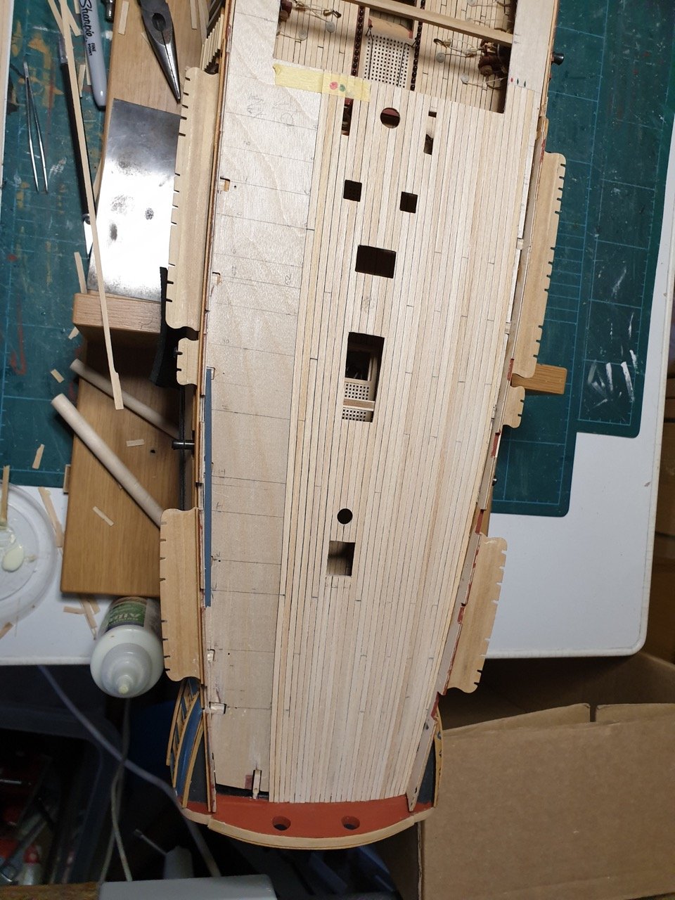
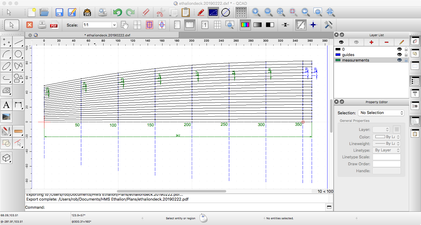
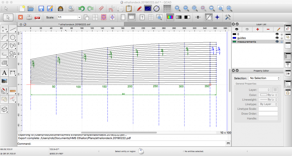
Hi all, Thanks as always for the likes and encouragement. The upper deck is glued in place and drying as we speak, so my thoughts have been on how to plank it... I didn't want to do the same style as the gun deck, but instead wondered whether I could manage the tapered planks that are seen on contemporary models and in the AOTS Diana. So... to QCAD... I'll add a longer update soon, but at the moment I thought I'd share the design I've ended up with... (Note I haven't marked the plank endings on this version, but it does give the taper... The file can be downloaded here as a PDF to be printed on A3. (It's based on the Caldercraft deck, and not the AOTS deck shape, so that it fits with the kit I'm building. Measurements are all in millimetres, and the outermost plank is the waterway. Each plank should be equal length, and although the outer planks will be slightly longer, it shouldn't be noticeable if I make them all identical - at least, that's the plan! I'll shape them all together, and then cut them to length as I lay them according to the pattern in AOTS. There are 21 planks per side. So - I've got strips of 4mmx0.5mm maple (to match the wood I used for the gun deck) from Cornwall Model Boats, who were wonderfully prompt as always! Thanks guys Here's the cad file. ethaliondeck.20190222.pdf Just as a point to note, on my model, the deck will actually run slightly further back than the false deck, as my transom finishes slightly further back. But that will probably vary model by model. Happy building Rob
-
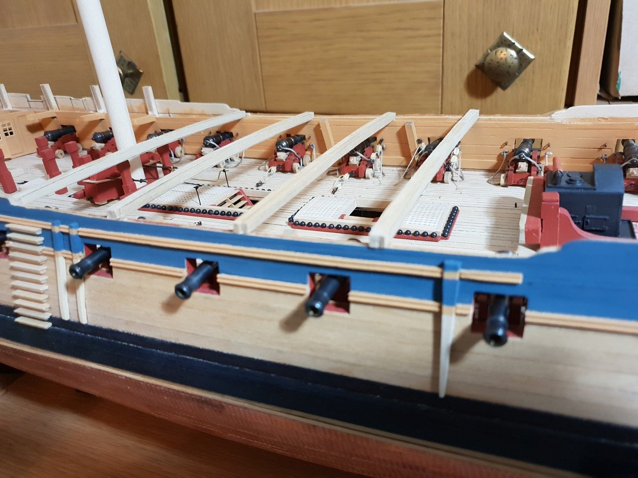
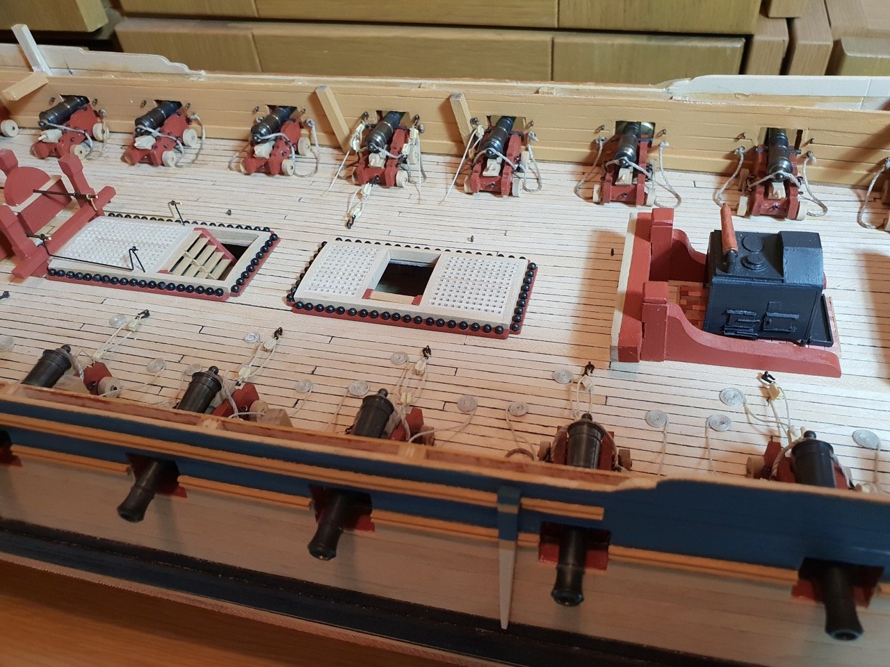
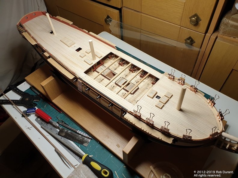
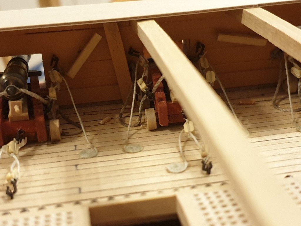
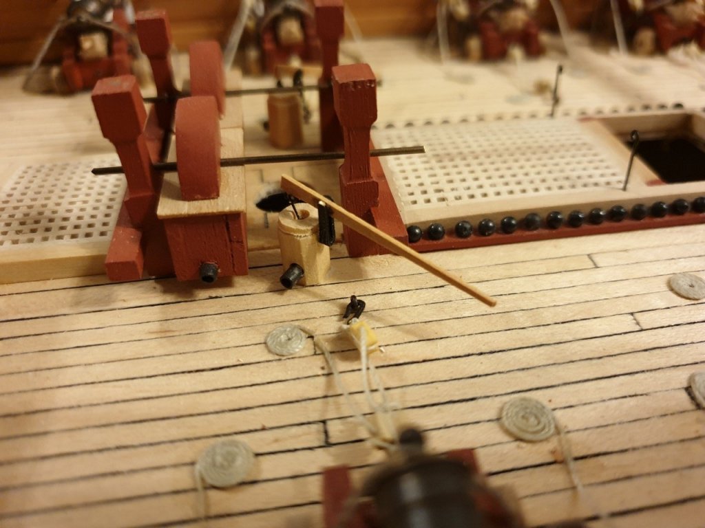
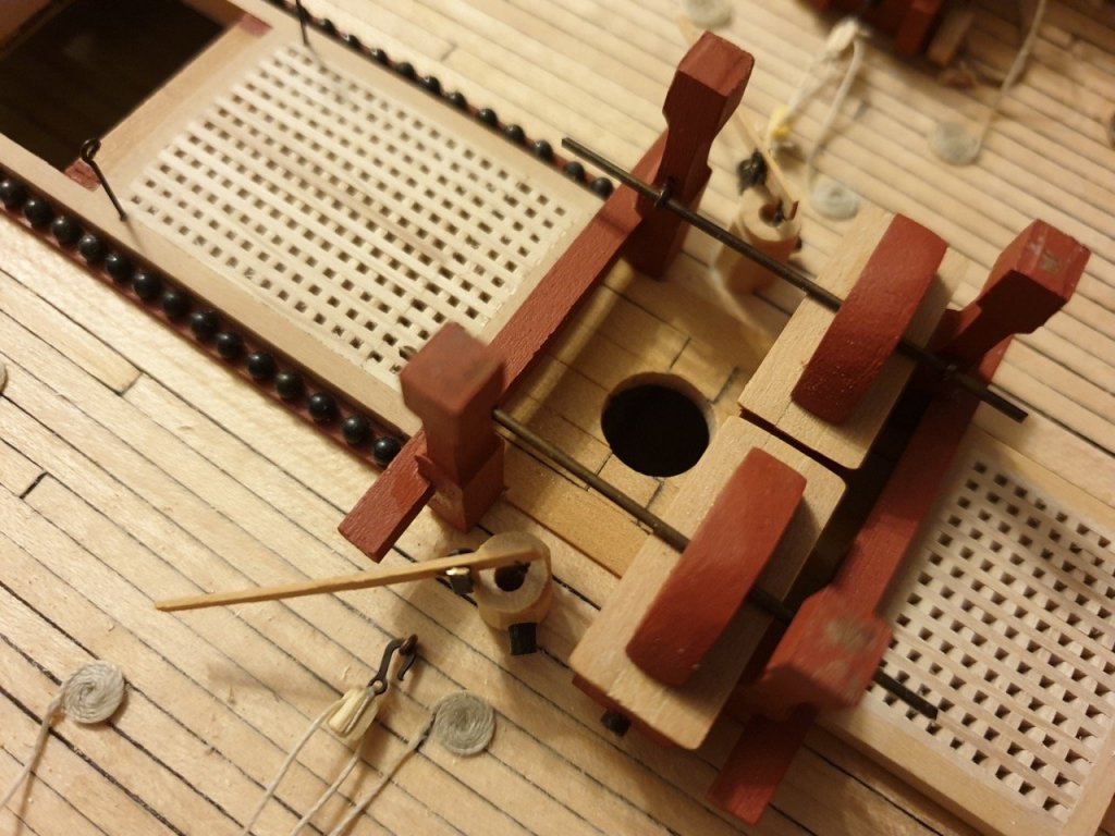
The chain pump's fixed in place, and the cleats on the bulwarks are finally there (I scratched them out of box)! A couple of stanchions to go, and I want to get the channel supports in place before I put the top deck on. Not far to go on the gun deck now! Feels like a major milestone! (Someone needs to get a broom out by the looks of it!) Test fitting the quarter deck / foredeck and gangways. Rob
- 275 replies
-
- 14
-
-
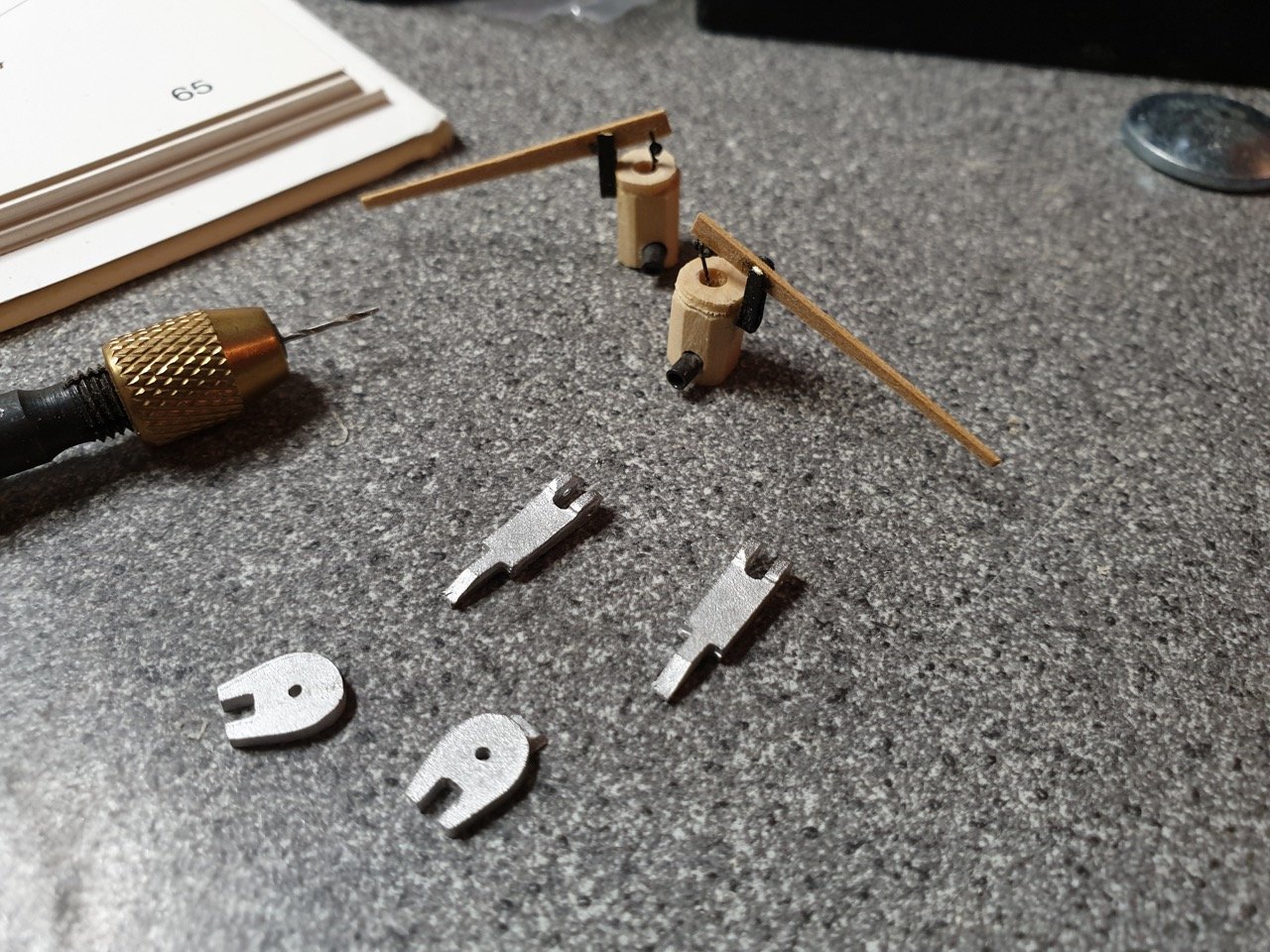
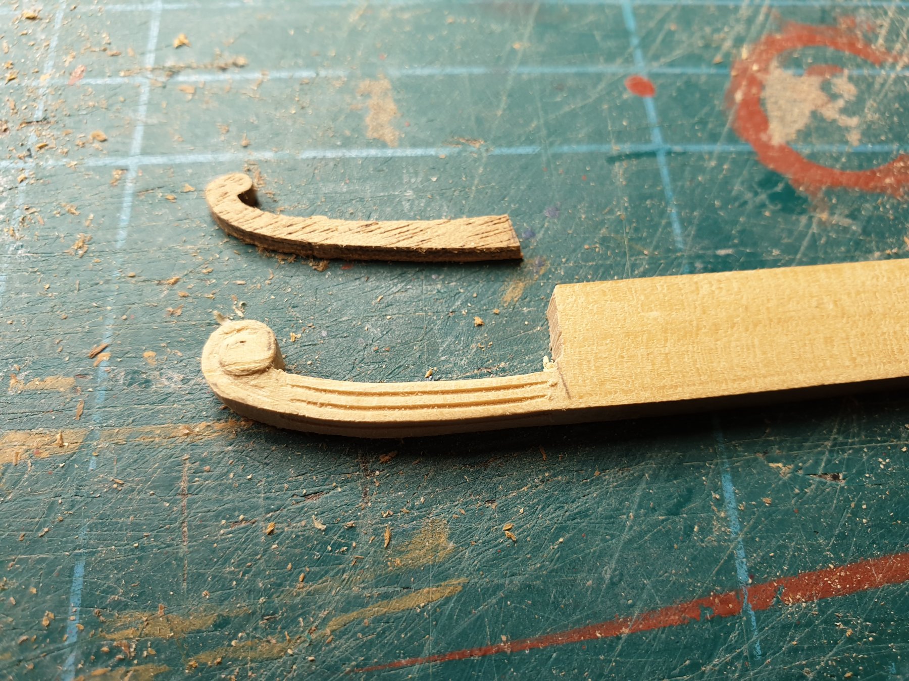
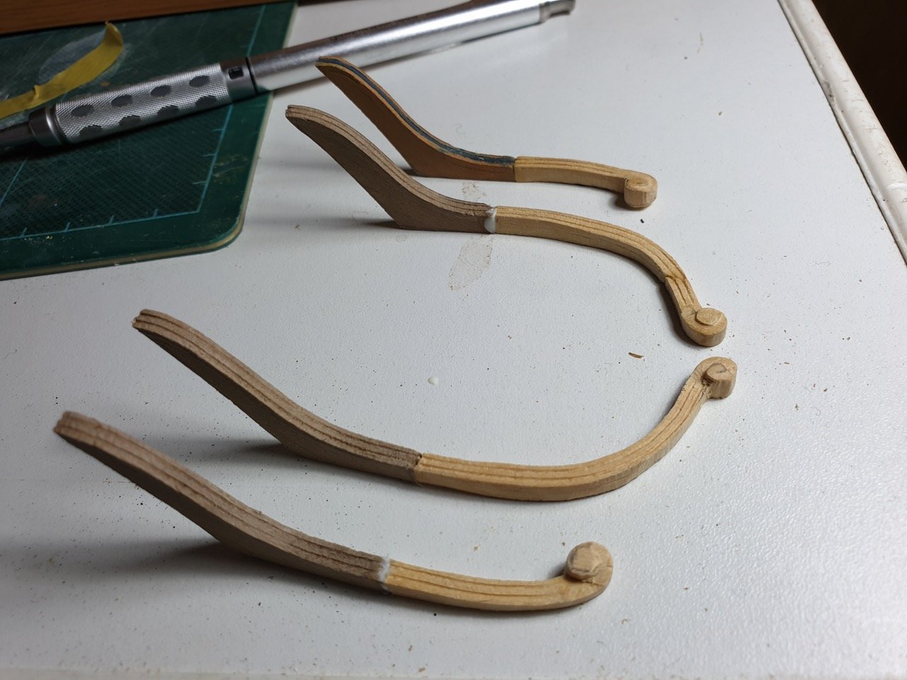
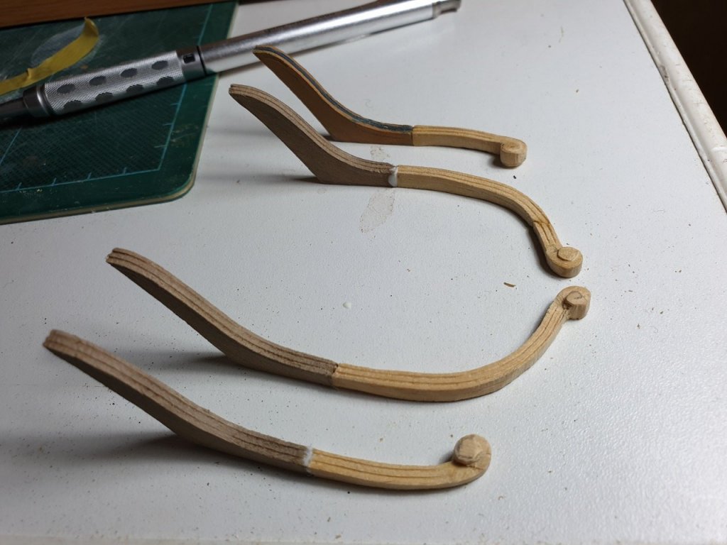
Oh yes, and I've been working on the sheer rails on the starboard side (mental note, must catch up on port side!). The scrolls were scratch built rather than use the walnut in the kit - those parts are reasonable wood, but seem to me to be slightly the wrong shape... Happy building Rob


- 275 replies
-
- 15
-
-
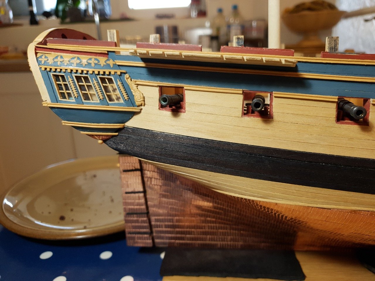
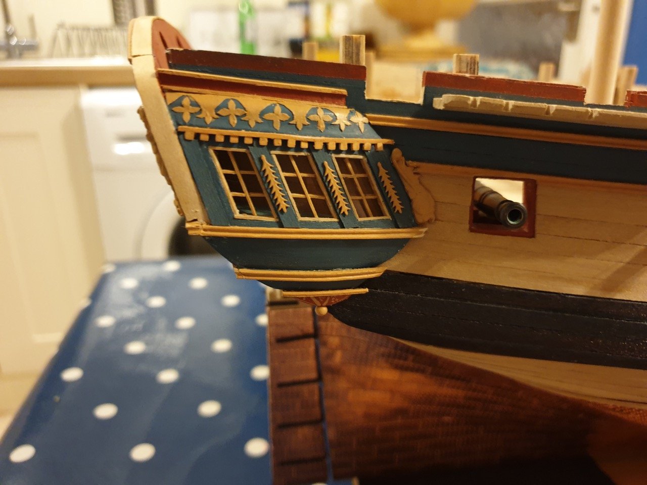
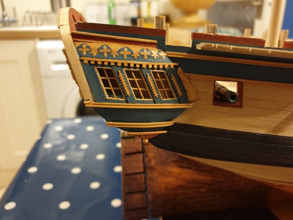
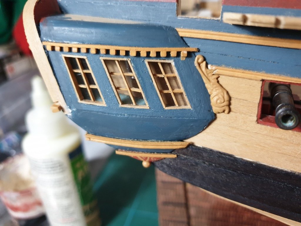
I've finished the starboard gallery now. I decided to mimic the decoration from the builder's model on the Greenwich collection here using painted paper... this meant I could design and print out the pattern and then cut it out, paint it, and stick it to the model because it _should_ form to the upper part of the gallery... At the moment the pva has made it rather glossy, but I'm hopeful that a coat of matt varnish will flatten it and make it look more in place with the rest of the gallery decoration. The "verticals" were added between the windows adding an extra element of depth, and the decorations added as per the stern. The close-up's brutal, but it looks rather nicer in person... I've also started attaching the deck furniture and adding the cross beams. (I still need to remember to add the cleats! MUST NOT FORGET!)... Yesterday evening I scratch built a couple of elm-tree pumps... The support for the handle supplied for the kit is the same width as the 1:24 diagram - that wouldn't do, so I used some spare photo-etch (chains from HM Schooner Pickle) to fashion a more fitting support for the handle. The pump links are Pickle photo-etch eyelets. Here they are with some of the kit parts in front of them... And in place... (the chain pumps are still waiting to be finished off an attached.) In the meantime my daughter and I have been doing some card modelling Not bad for a ten year old! Happy building Rob


-
Thanks Jason - I agree completely... They're our models, aren't they... I figure it's a bit like becoming her captain and dipping into my own funds to make her my own. The lovely freedom of building them ourselves. Thanks B. E. It's the encouragement that keeps us going
-
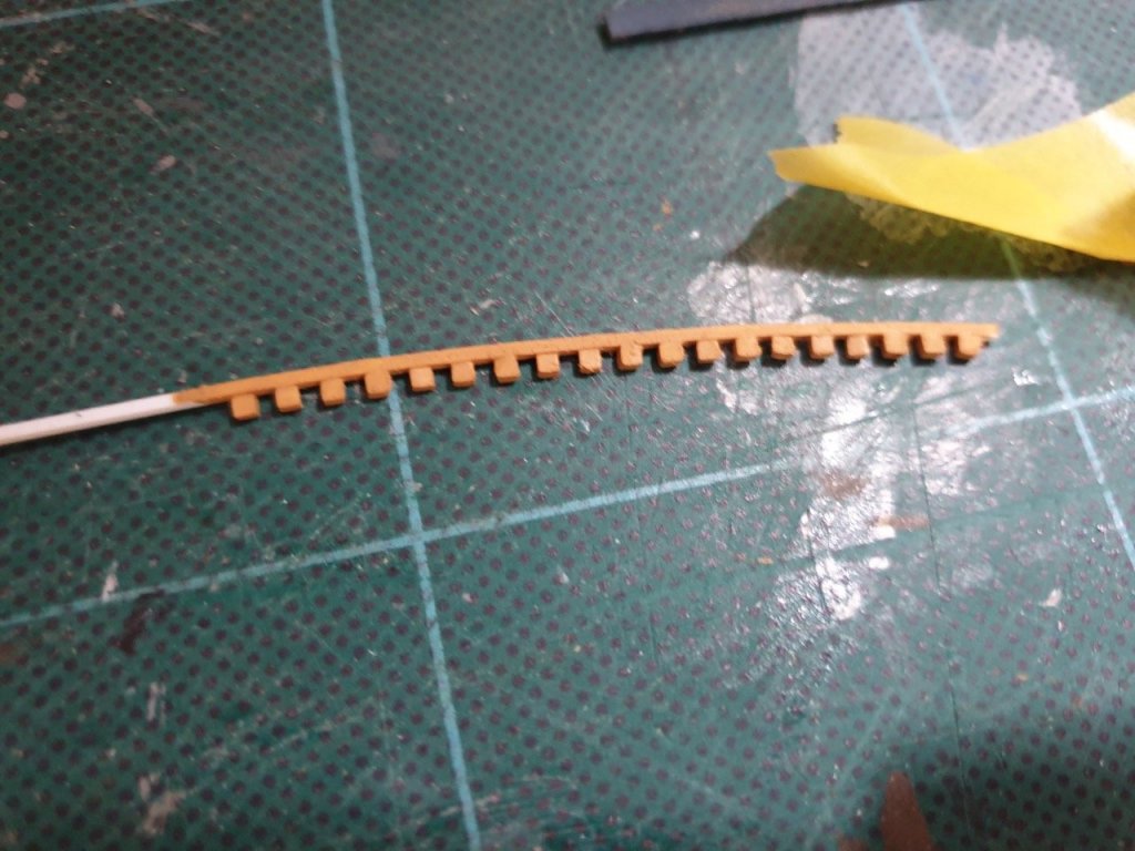
Back to the stern galleries... I'd left these for a while before completing the decoration (I got a bit tired of them and needed a break!)... but having got the cheeks on the bow, I figured it was time to get on with finishing them off. I'd noticed a nice kind of inverted crenellation above the windows, and thought I'd have a crack at that. It was beyond my wood working abilities, but I'm, not proud, and this area is painted, so the styrene came out They were tiny little things, and I didn't want to stick them to the cutting mat (styrene glue melts it), so I masking taped the strip to the edge of a metal ruler and used that as the building board... The squares were from a square strip cut thinly, glued so the cross section was visible..., that way I got even squares. It did mean I had to sand it down to get it nice and flat once glued, which took a few attempts, and various bits had to be reattached. Looking at it now on these blown up pictures, the rear end may need lifting a little (darn those big monitors!) I'll have another look and see if it's just the angle of the shot, as it is taken slightly from above. Happy building! Rob
-
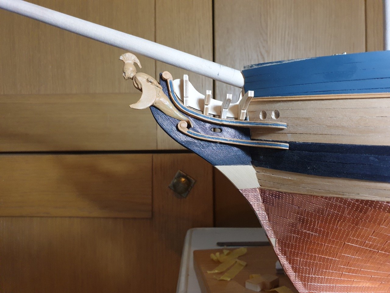
Time for an update... I've been working on the bow area, and in particular the cheeks and head rails... I wanted to replace the kit parts as they are pretty meagre... kit part top, my part bottom. I'm pretty pleased with how it turned out... This is the progress so far... With the different figurehead a bit of playing around was done before I settled on a layout - the dolphin's tail going between the scrolls... Finally I drilled the hawse holes through the hull (pretty scary!) ready to have the reinforcement added to the lower half. Next up are the head rails and timber heads! Looks like it just might come together. Rob


-
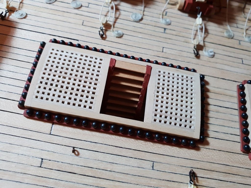
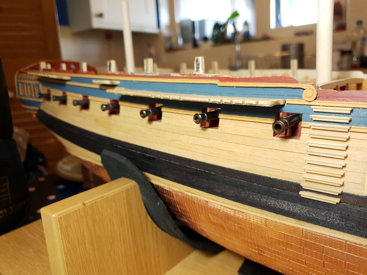
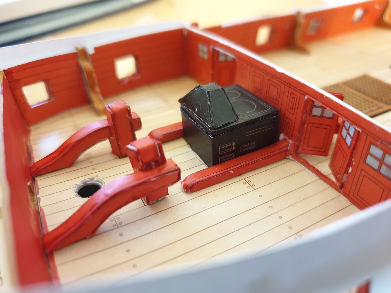
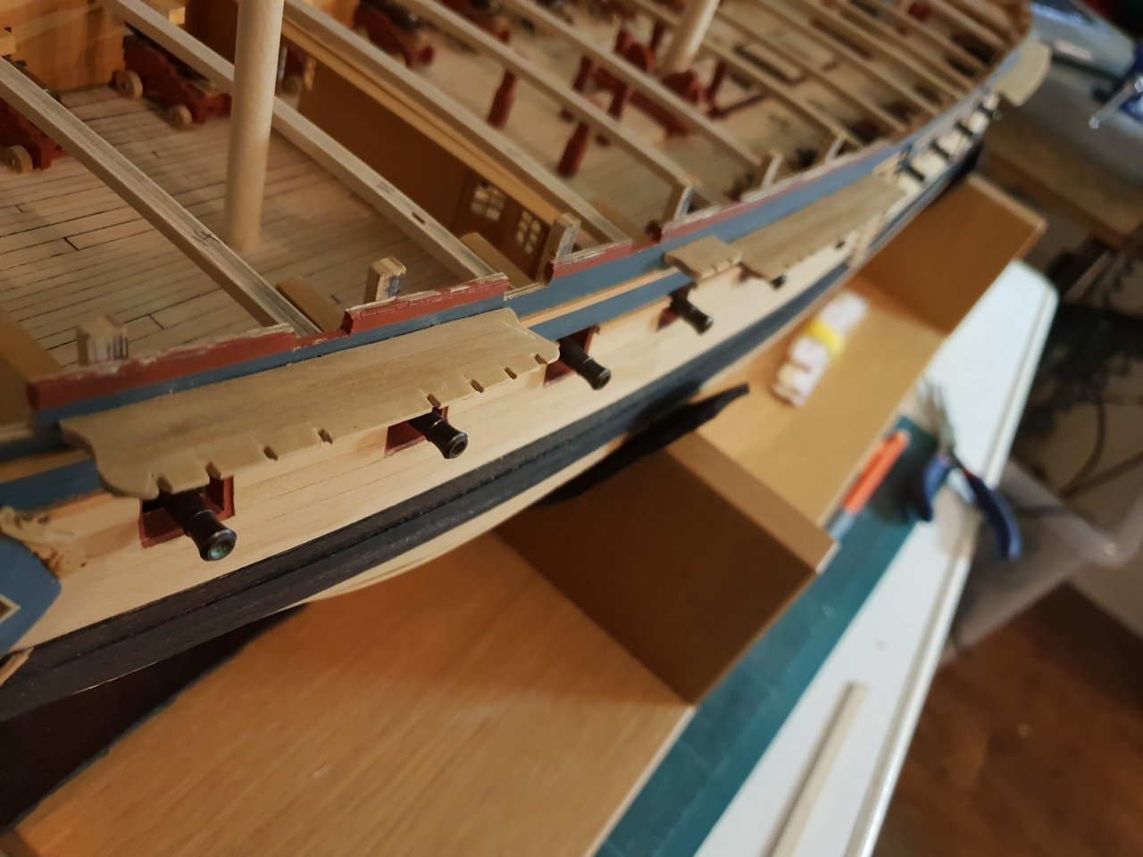
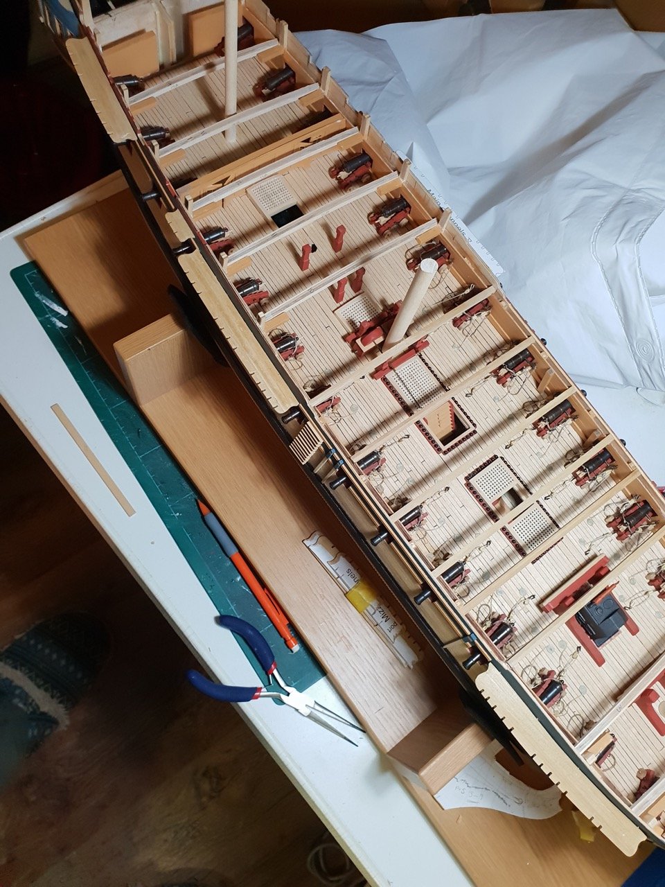
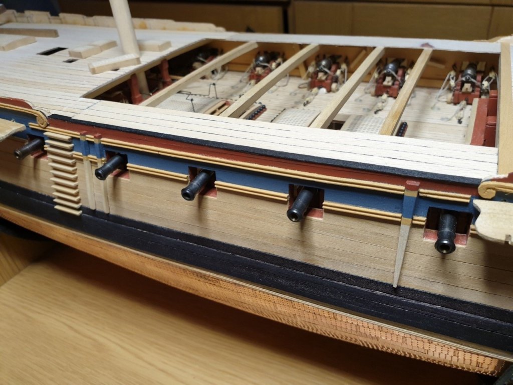
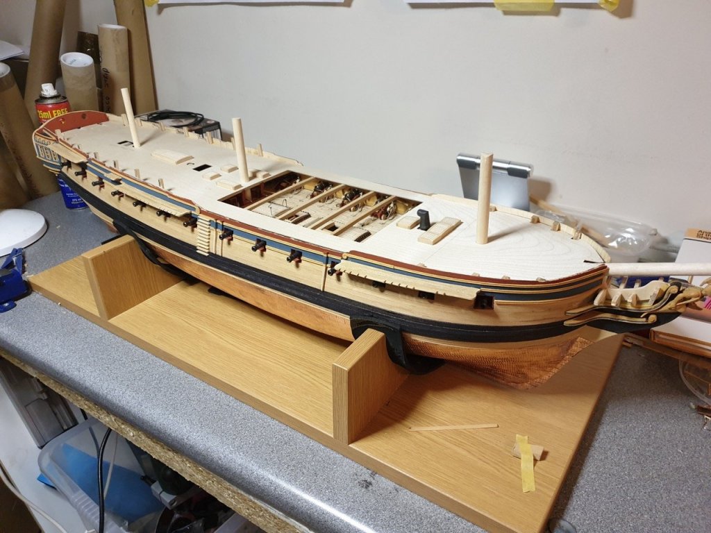
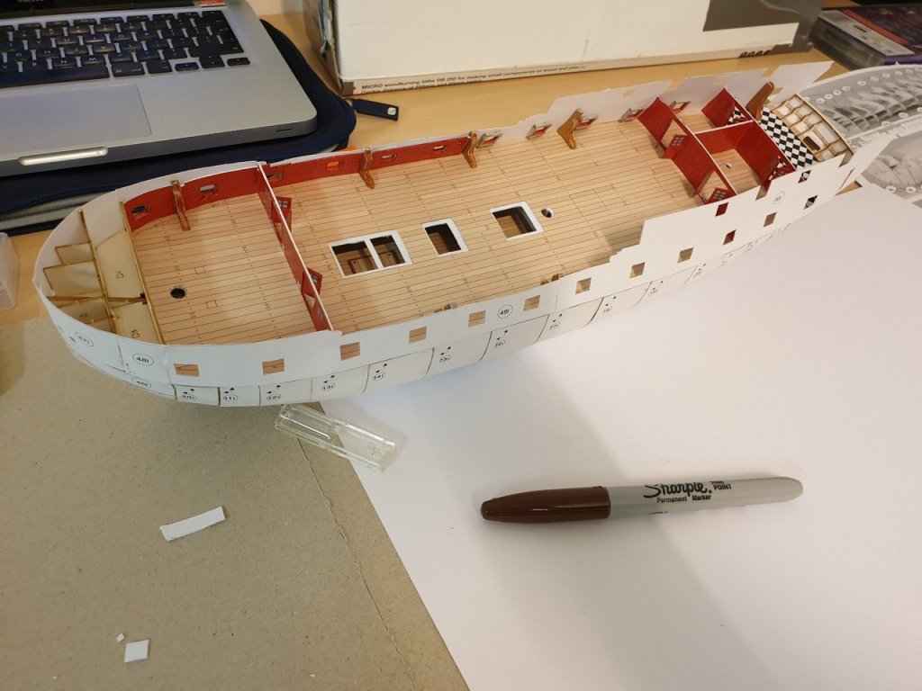
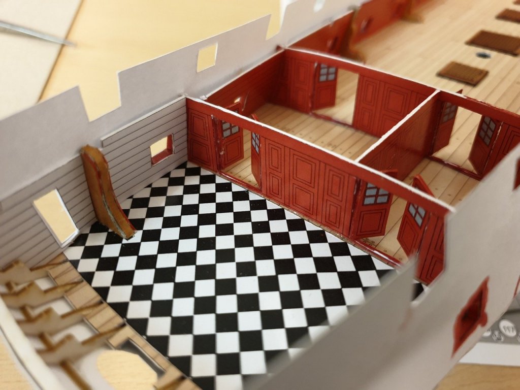
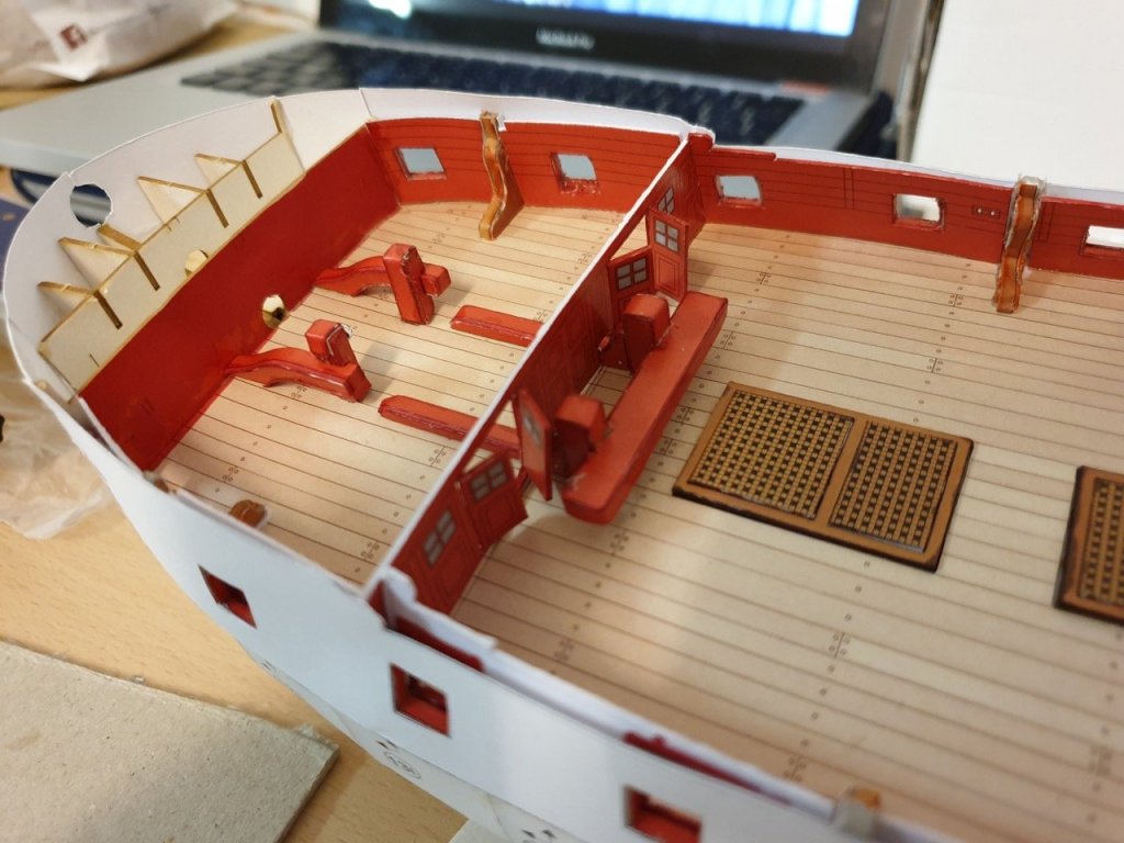
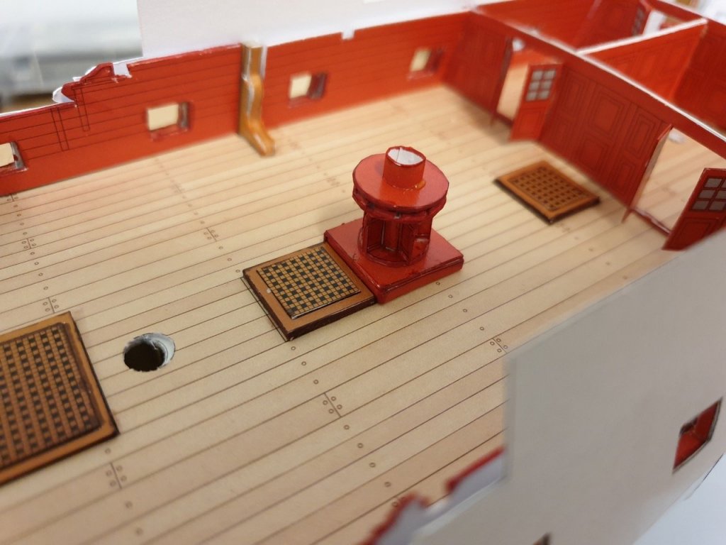
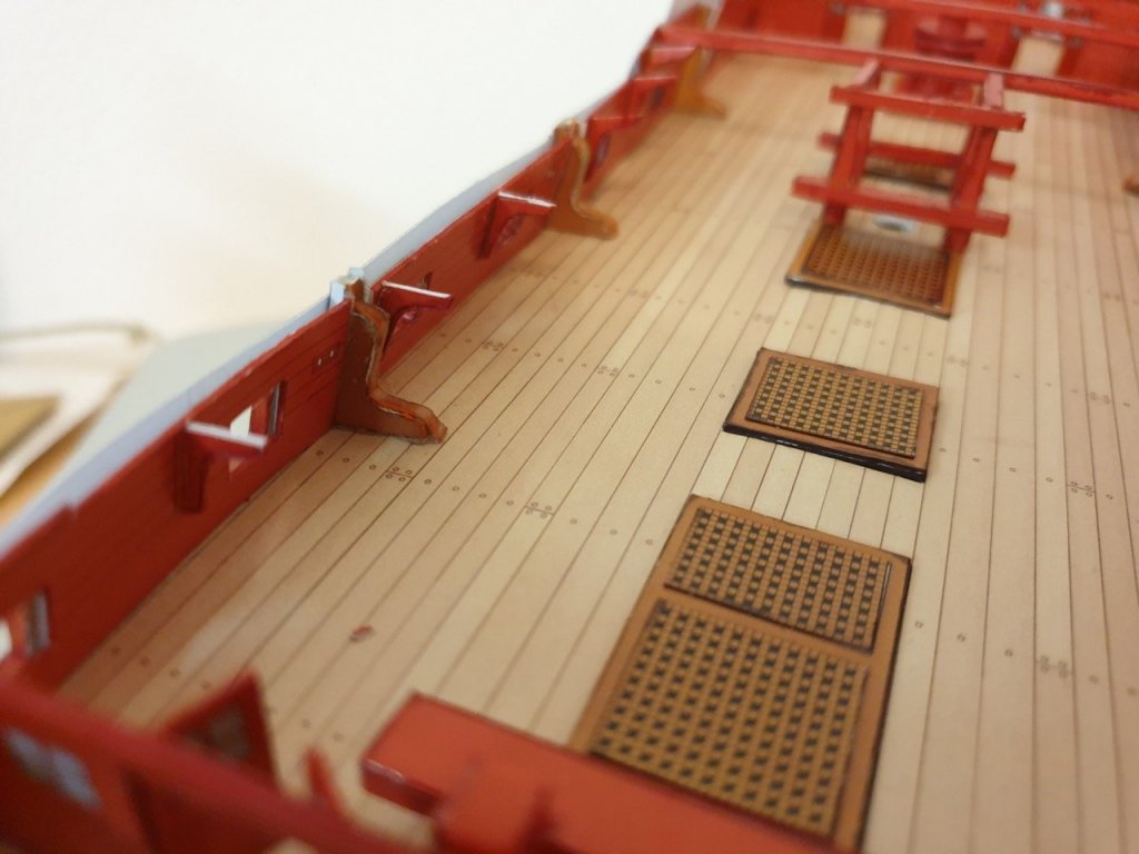
Well, I've had the opportunity for another trip to Germany, so I have an update to share Here's where I left off last time - gunport linings on the starboard side, and starting to put the inner bulkheads in. I managed to complete the bulkhead linings, and gunports on port and starboard. Once done, the rear of the captain's cabin is lined, and then it's onto furniture for the deck. I decided to have the gratings closed, which meant putting furniture in the captain's cabin was a bit over the top. Nice to have the option, though, and the fore and quarter decks aren't stuck down yet so I can change my mind later. The bitts were made up, and stuck down. And the ship's stove was made up - again this won't be seen once it's all together, so I haven't put all the possible detail on it... (builder's prerogative) You can see how shocking my card building ability is here... but from a little way back it looks a bit more acceptable. The main thing is, I'm enjoying it, and I'm learning a lot!! I may end up building another one of these once I've gained more skills The capstan was made up... An overview of the deck so far... My biggest friend so far has been a bunch of sharpie markers which have covered a multitude of sins (or at least, made them less obvious!) You can just about make out a blurry cross beam at the bottom of the photo above - the beams were put in place at this stage ready to take the quarter and fore decks. These decks have been cut out and dry-fitted in position ... I haven't fixed them yet as I haven't put the gun carriages together... more on that below. I didn't fancy the task of trying to put together the gun barrels for this ship - it was a step too far for me... so I had a look round and worked out what size they should be. As 9lb they end up around 28mm at 1:96, so I ordered a set of brass cannon from Cornwall Model Boats, and they arrived at home while I was in Germany (hence not being able to fit them straight away...) - I've brought the gun carriages home to assemble, so I can take them back out ready to fit... YOu can see how many parts they have in the circle on the plan above. Finally, I started to put the out layer of the hull on. This has to be done very carefully to get the best finish possible. I chose the 1795 colour scheme to contrast my build of Ethalion. Given that it isn't wood, I wasn't quite bothered about getting a nice wood coloured finish on the hull. It also saves all the painting of the white areas... At least, I don't have any of the decorative blue strips in my kit and assume that they are to be done by hand... they all have an RZ prefix on the part? Care is needed to distinguish the parts for the earlier and later colour schemes - it seems that the later scheme has extra parts on two extra sheets, so I checked those sheets first for each part. Here's the progress as I left her in dry-dock. Happy building. Rob


-
Hi Gary. I've sent you a PM. Sounds uncomfortably hot.... UK's been having snow... my children were very excited... not sure everyone agreed Rob
-
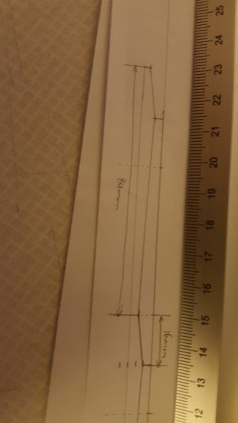
Hi Gary Hmm... not sure why my PM isn't working... anyway.. welcome to the Diana club and here are the dimensions. The planks taper to half their width at both ends... 96mm long. 80mm for the longer taper and 16 for the shorter. From my memory the planks were 5.5mm at their widest extent. Happy to put the jig in the post if you want?
-
Thanks OC. Yes, that's a timely reminder. I do need to do that. Thanks Jason. I completely agree and had planned on following suit. The cleats look really neat on your build. Thanks to all for the likes and encouragement as always
-
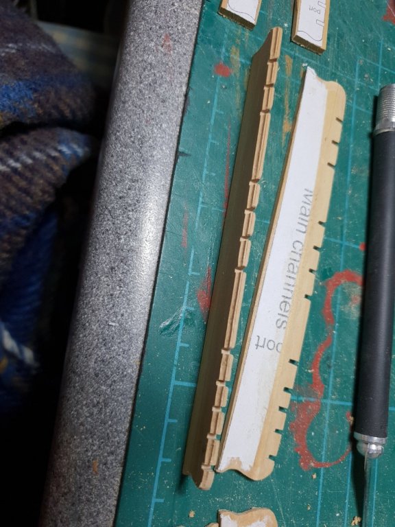
Sadly boxwood is so expensive - at least it seems to be here in the UK - that I would imagine the cost of using it (or indeed many other finer hardwoods) would put many off buying the kits, but the colour of the ply for the channels is so different to that of the rest of the walnut that I wouldn't have wanted to use it for anything that wasn't painted even if I was using walnut. Thankfully, being a hobby, we're free to swap and change as we see fit When I built Sherborne and Pickle the ply was a much closer match to the outer planking material and seemed to have a much finer grain albeit a bit fragile - perhaps this ply isn't walnut at all? When all's said and done, I could have built Diana out of the box, and I'm sure it would have made a handsome enough model, but this is more fun!!, takes longer (a financially agreeable knock-on effect), and I'm learning lots more as I go. Here's a picture of the variation in wood colour (taken under a daylight bulb). The channels are on a sheet of the reddish ply shown at the bottom identified as 2mm walnut in the parts. The parts above are the 5mm walnut (the skid beams which I have already replaced with box on my model).

-
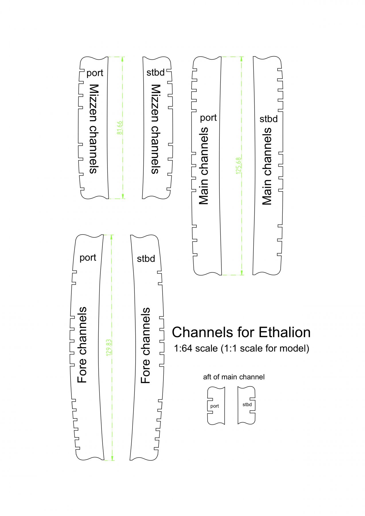
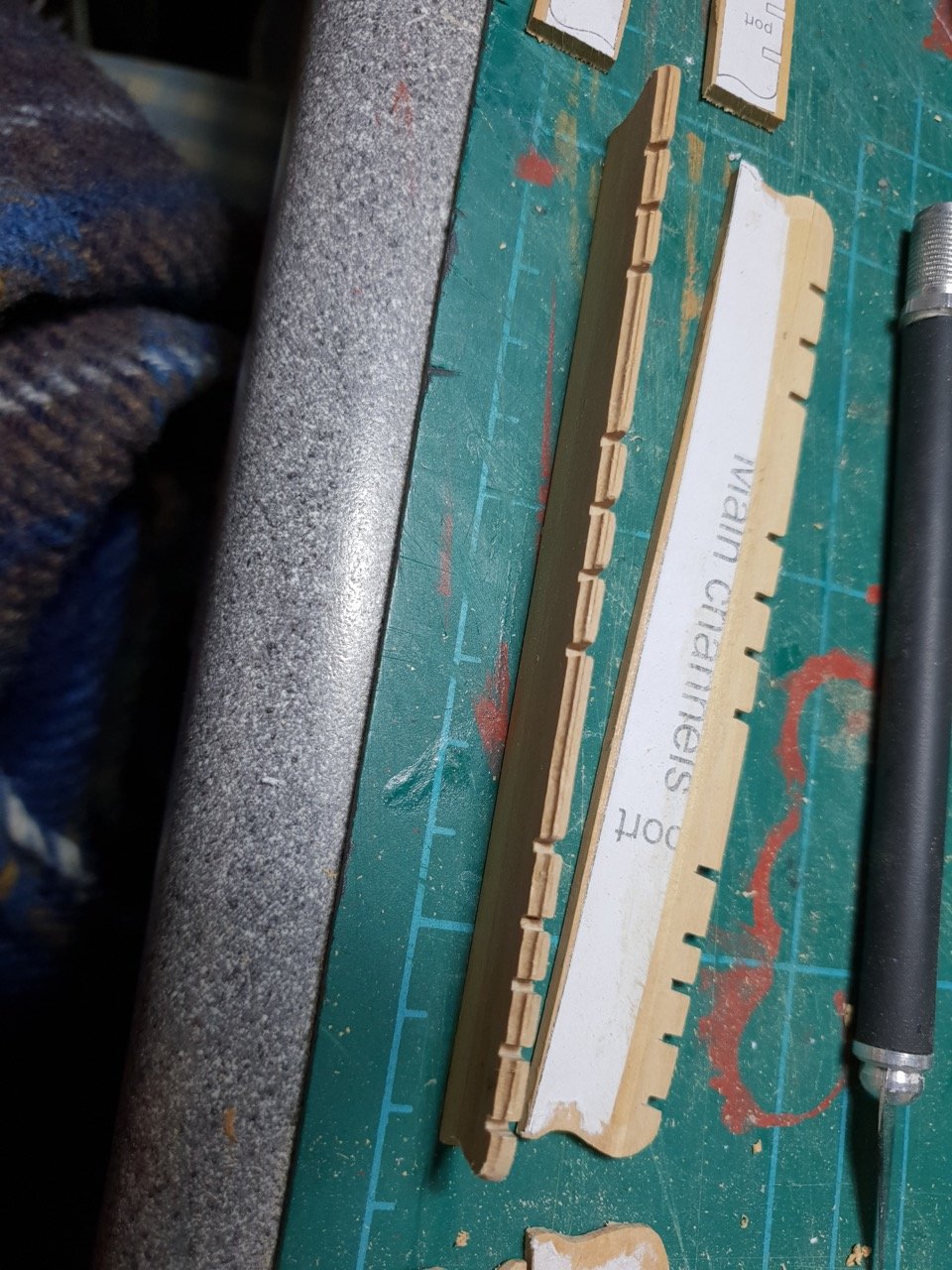
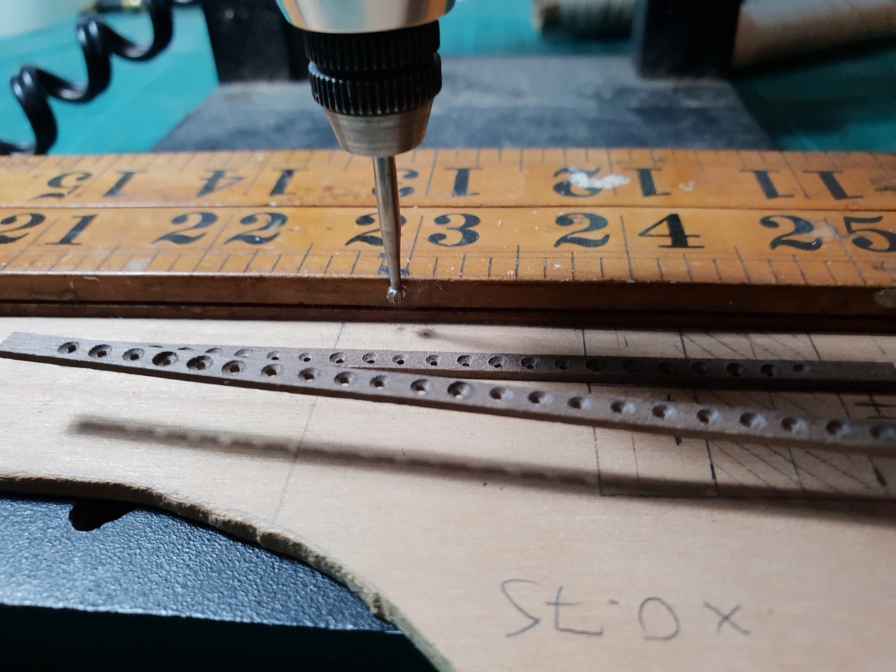
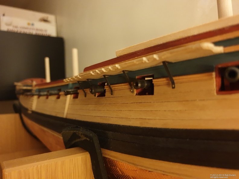
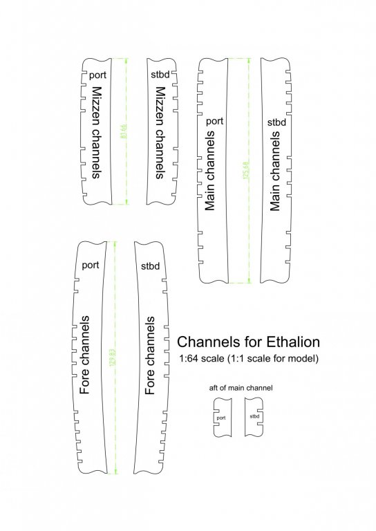
Hi all, Since my last post, I've dry-fitted the skid beams and begun working on the channels. These were drawn out in cad to work out the basic shape based on AOTS and the NMM plan of Ethalion. Interestingly the foremast channel (in AOTS and the Ethalion plans) only has five slots at the rear end compared to the six on the caldercraft kit... I've followed AOTS, and at some point I'll hopefully work out the difference in rigging between kit and AOTS. Anyway - here's a PDF of my channels plan... ChannelsV2.pdf As I don't have access to 2mm sheet, I laminated 2x6mm guitar stringers to make up the channels. I needed three wide for all but the fore channels which were four wide. The plans were pritt-sticked onto the sheet and then cut out using a small plane, files, and the slots cut undersize with a saw and a file used to make them uniform. A grooved edge was scraped into the channels. Once the chains are in place, I'll use strip to fill the gaps and sand it gentle back to match the profile. Pins were added and the positions marked on the hull. So far, I've dry-fitted the starboard channels. I'm pleased with progress so far. It took a few attempts to get the smaller channel aft of the main channel to the right height so that it matched the mizzen channel, but I think we're there now. It wasn't too bad doing this step with the guns installed, but care does have to be taken not to drill too far into the hull when making the holes for the pins. A strip of masking tape round the drill bit did the job wonderfully. Happy building! Rob


-
Oh dear... I may well become the test case for that theory... my guns are installed and I haven't begun the channels yet. Those brackets look perfect! Happy new year Jason!
-
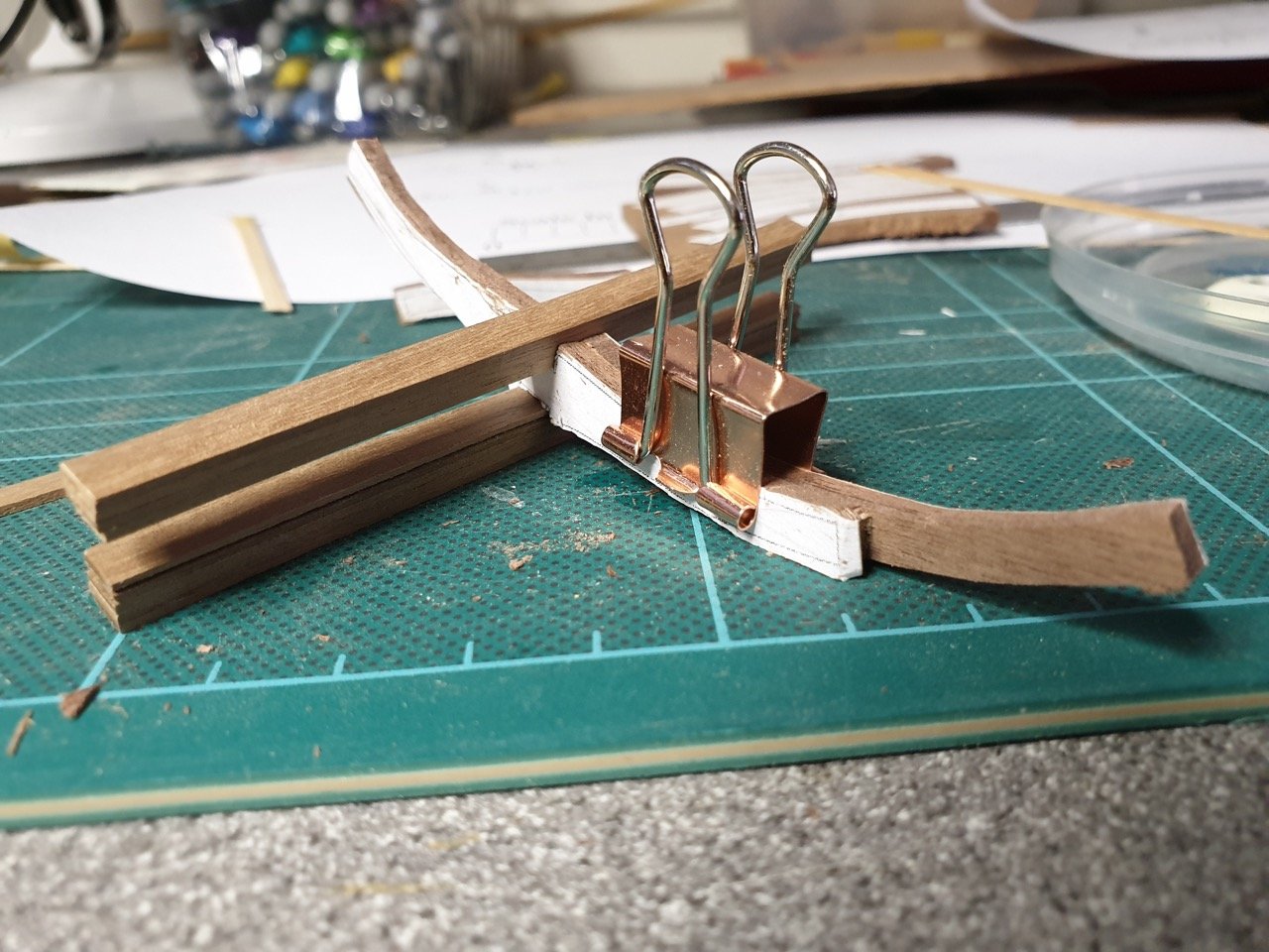
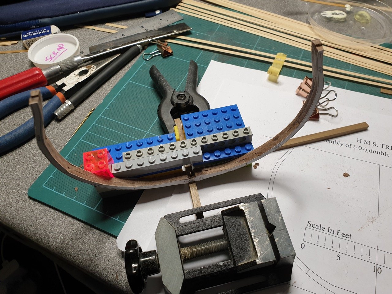
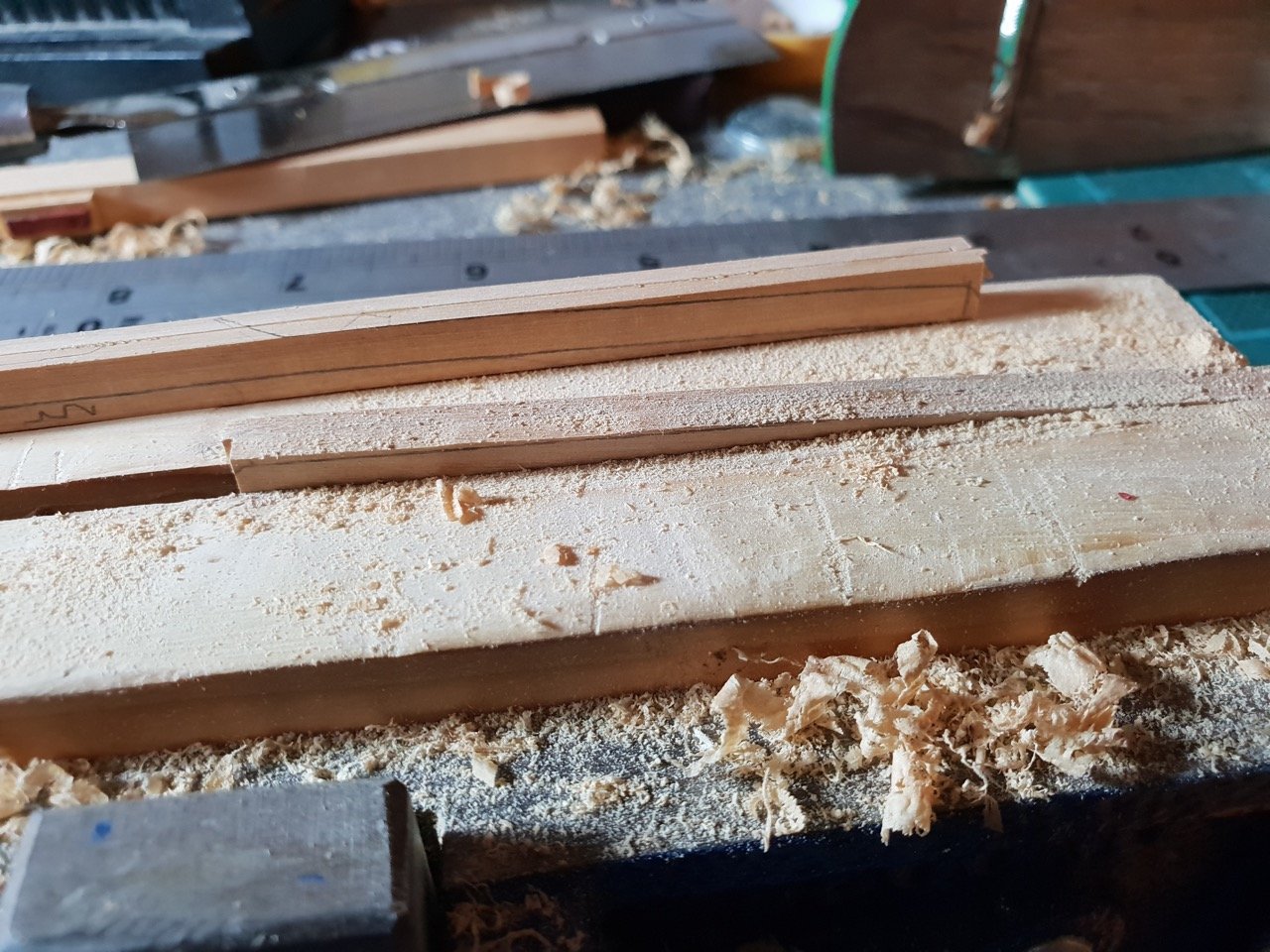
Happy new year! Hope everyone's having a great start to 2019. Gun rigging is continuing apace... Not much difference to show in photos, as I've mainly been rigging blocks and making up training tackles. To add a little variety, I started working on the beams that will cross the gap between the walkways. These are provided in the kit as six beams in walnut. (part 44)... having done so much of the build with Walnut, I wanted to keep with that option. I considered trying to bend the box, but I was concerned that it would quickly spring back. Instead, I decided to shape them from 6mmx2mm stock. The box strip was laminated to make up the 4mm width, and then the walnut part used as a template. Parts sat roughly in place...


- 275 replies
-
- 11
-
-
As an aside, it turns out that Flickr are limiting uploads to 1000 pictures on their free accounts (I get why these sites are all doing this - no hard feelings), so I've moved all my photos onto my own hosting. It turned out considerably cheaper than paying flickr for the privilege, and comes with the added benefit that I'm in complete control of it all now. So... the in-between photos of the build that I don't post on this site are all here... https://www.durant.biz/
-
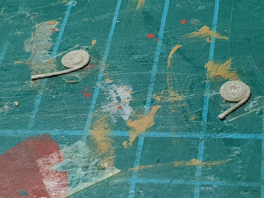
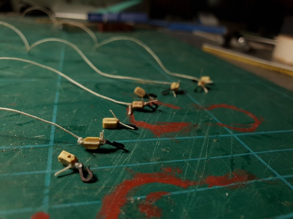
Happy Christmas to you all I've had a wonderful Christmas so far, and it's included some time to work on Ethalion. I've completed the rigging of guns 3-9 on the starboard side, and started guns 3-9 on the port. Eventually I remembered that double-sided tape was far better than masking tape wrapped round for making the coils of rope. The extra stickiness made life much easier. I've also finished making up the shot racks that surround the gratings on the upper deck. A simple jig was made to align the drilled holes. Anyway - back to making training tackles... (12 pairs of blocks still to rig!) Happy building Rob