scrubbyj427
-
Posts
1,723 -
Joined
-
Last visited
9 Followers


About scrubbyj427

- Birthday May 13
Recent Profile Visitors
5,181 profile views


-
 brunnels reacted to a post in a topic:
HMS Portland 1770 by scrubbyj427 - 1:48 - 4th rate 50-gun ship
brunnels reacted to a post in a topic:
HMS Portland 1770 by scrubbyj427 - 1:48 - 4th rate 50-gun ship
-
 Chuck reacted to a post in a topic:
HMS Portland 1770 by scrubbyj427 - 1:48 - 4th rate 50-gun ship
Chuck reacted to a post in a topic:
HMS Portland 1770 by scrubbyj427 - 1:48 - 4th rate 50-gun ship
-
Chuck reacted to a post in a topic:
HMS Winchelsea 1764 by Kusawa2000 (Mike Draper)
-
CaptMorgan reacted to a post in a topic:
HMS Portland 1770 by scrubbyj427 - 1:48 - 4th rate 50-gun ship
-
Jack H reacted to a post in a topic:
HMS Portland 1770 by scrubbyj427 - 1:48 - 4th rate 50-gun ship
-
rcweir reacted to a post in a topic:
HMS Portland 1770 by scrubbyj427 - 1:48 - 4th rate 50-gun ship
-
marsalv reacted to a post in a topic:
HMS Portland 1770 by scrubbyj427 - 1:48 - 4th rate 50-gun ship
-
marsalv reacted to a post in a topic:
HMS Portland 1770 by scrubbyj427 - 1:48 - 4th rate 50-gun ship
-
marsalv reacted to a post in a topic:
HMS Portland 1770 by scrubbyj427 - 1:48 - 4th rate 50-gun ship
-
marsalv reacted to a post in a topic:
HMS Portland 1770 by scrubbyj427 - 1:48 - 4th rate 50-gun ship
-
 Lovely work Chris! Very nice job with the fairing.
 -
scrubbyj427 reacted to a post in a topic:
La Renommee 1744 by ChrisLBren - 1/48 - 2025
-
L'Amarante by marsalv - 1:36 - POF
scrubbyj427 replied to marsalv's topic in - Build logs for subjects built 1501 - 1750
Absolutely beautiful work!!! -
scrubbyj427 reacted to a post in a topic:
L'Amarante by marsalv - 1:36 - POF
-
scrubbyj427 reacted to a post in a topic:
L'Amarante by marsalv - 1:36 - POF
-
scrubbyj427 reacted to a post in a topic:
L'Amarante by marsalv - 1:36 - POF
-
scrubbyj427 reacted to a post in a topic:
L'Amarante by marsalv - 1:36 - POF
-
scrubbyj427 reacted to a post in a topic:
L'Amarante by marsalv - 1:36 - POF
-
scrubbyj427 reacted to a post in a topic:
L'Amarante by marsalv - 1:36 - POF
-
scrubbyj427 reacted to a post in a topic:
L'Amarante by marsalv - 1:36 - POF
-
 scrubbyj427 reacted to a post in a topic:
L'Amarante by marsalv - 1:36 - POF
scrubbyj427 reacted to a post in a topic:
L'Amarante by marsalv - 1:36 - POF
-
scrubbyj427 reacted to a post in a topic:
L'Amarante by marsalv - 1:36 - POF
-
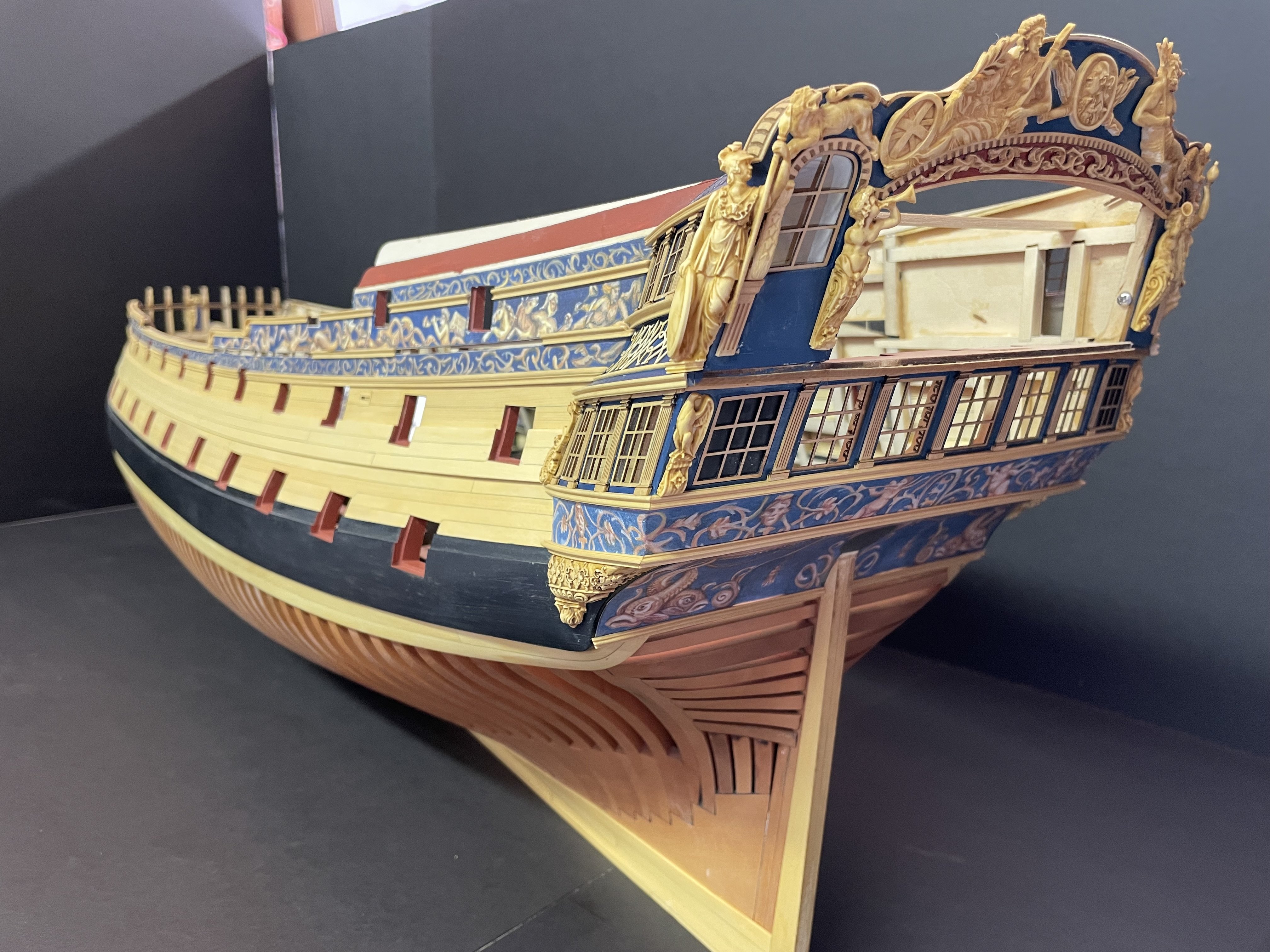
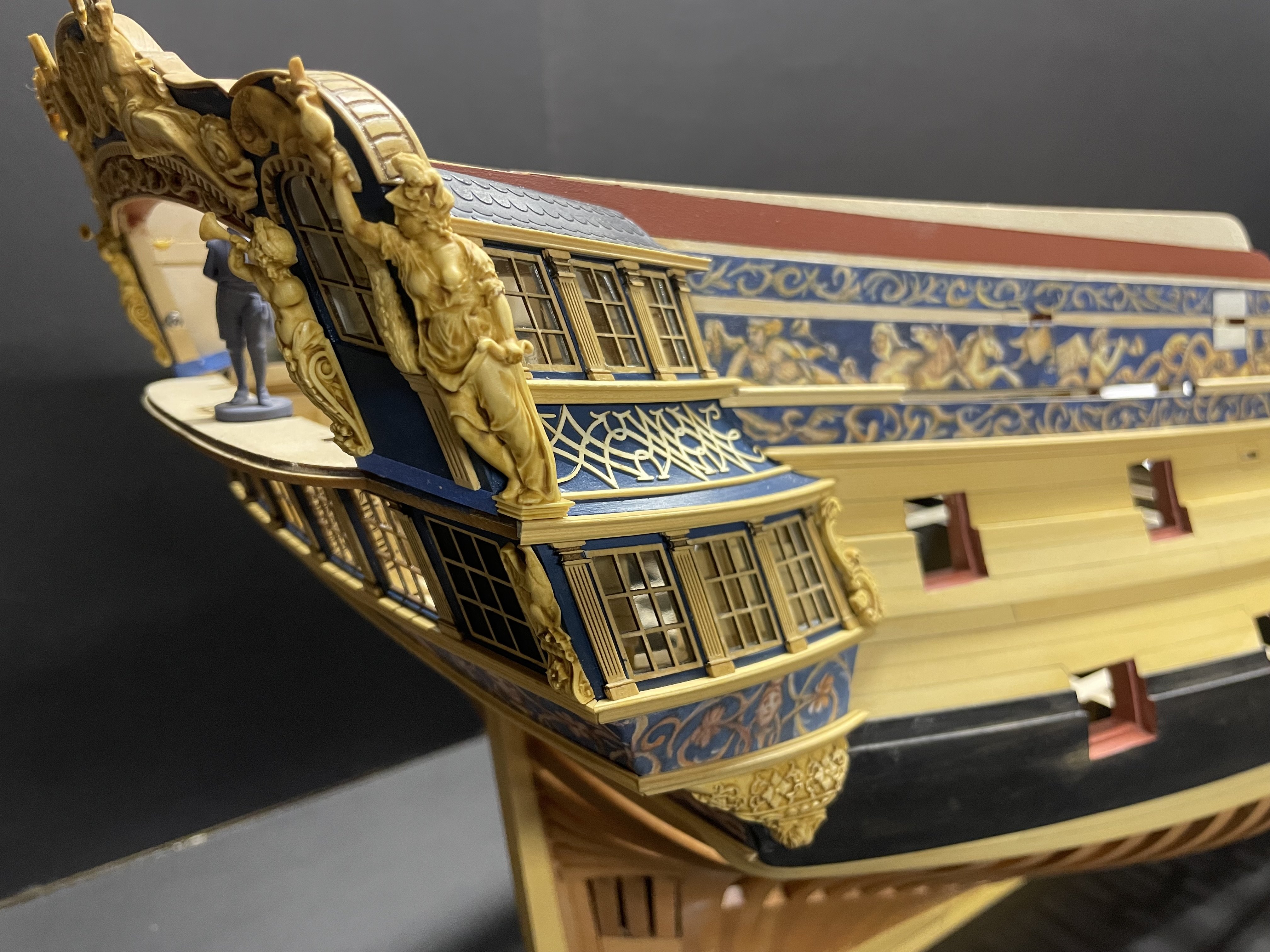
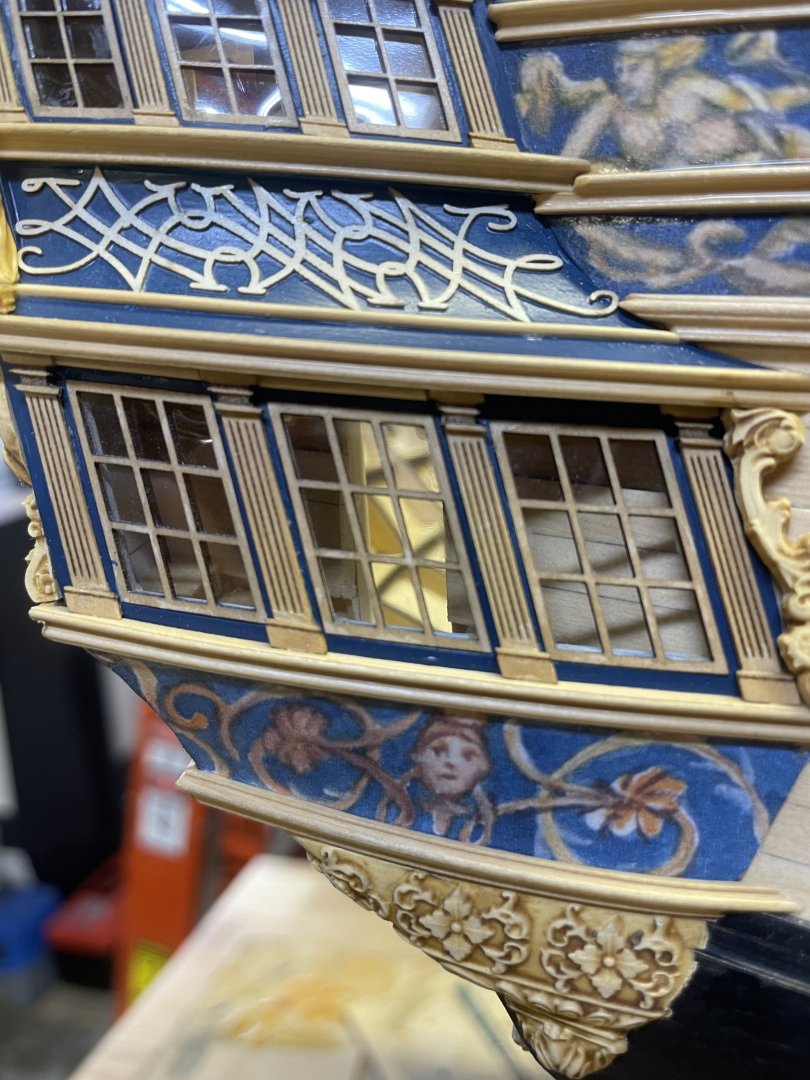
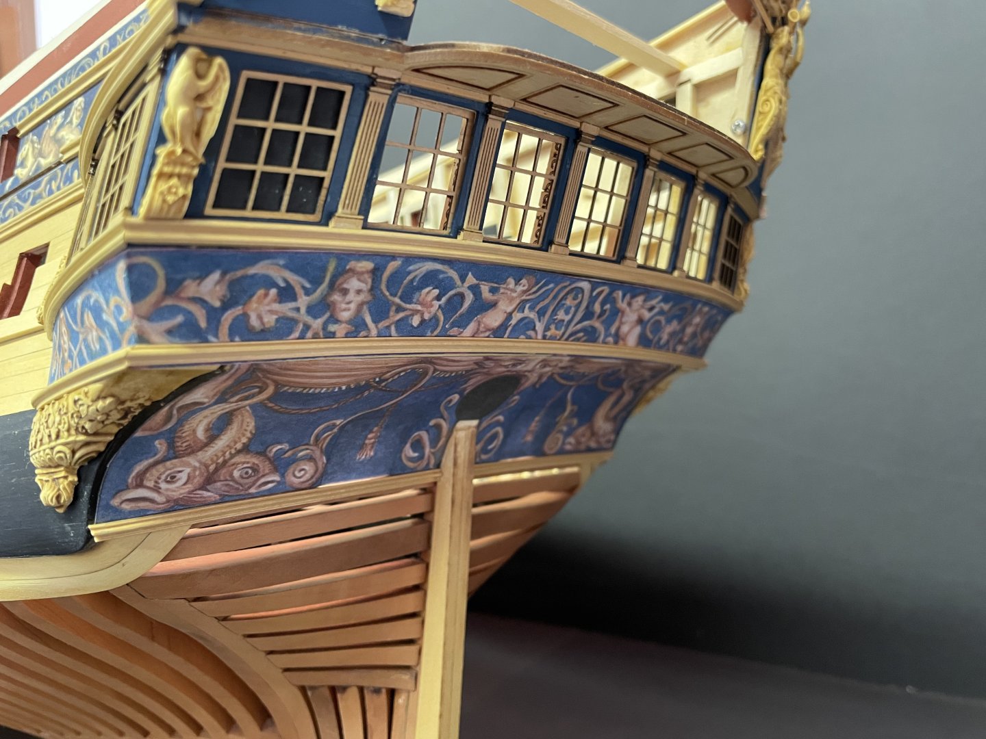
I did mine in white as I’ve seen some other models finished this way, I liked it at the time, In hindsight I would now prefer them left natural as Chuck did and on the contemporary model. But it’s not bad and I can definitely live with it.
-
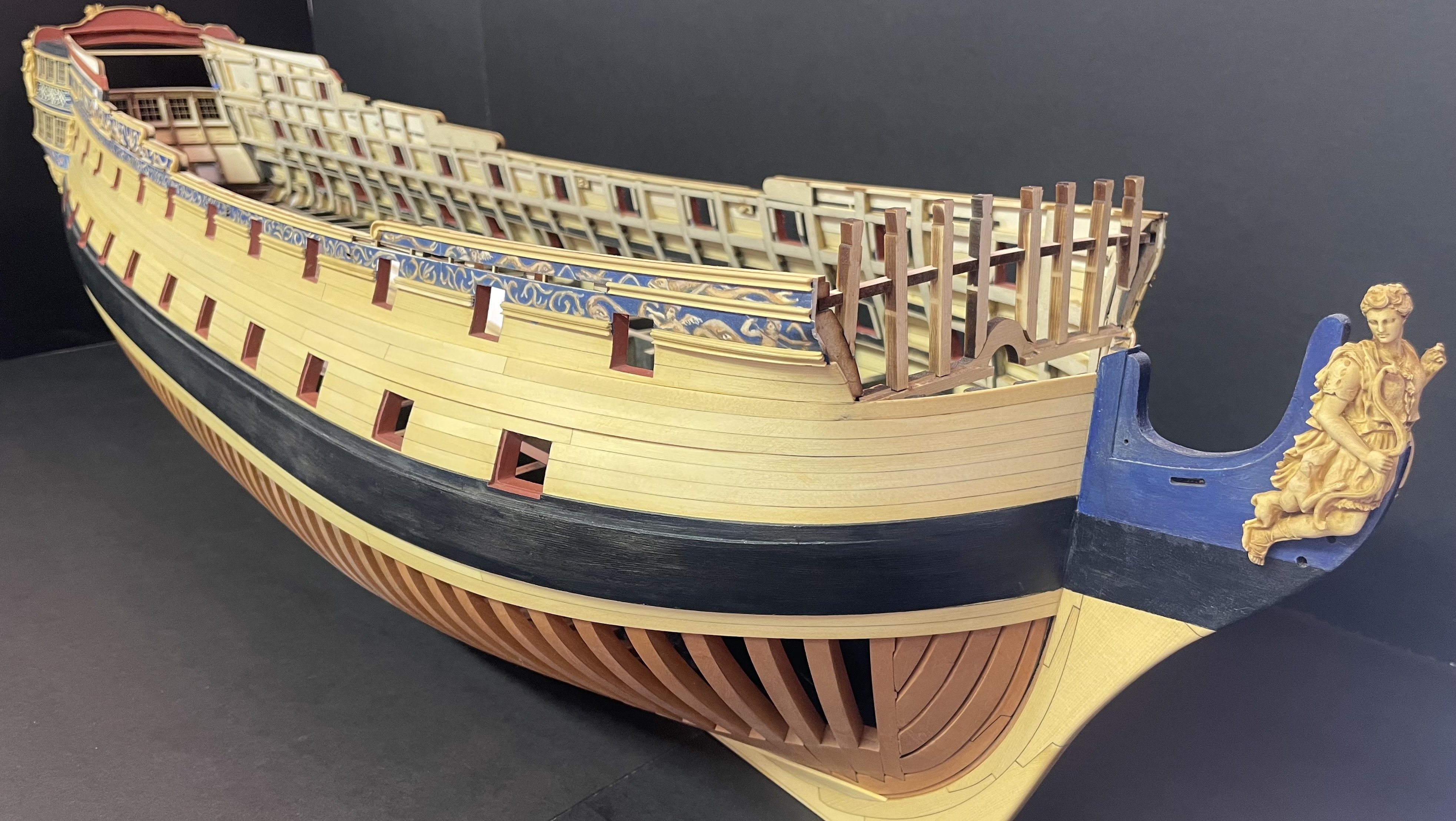
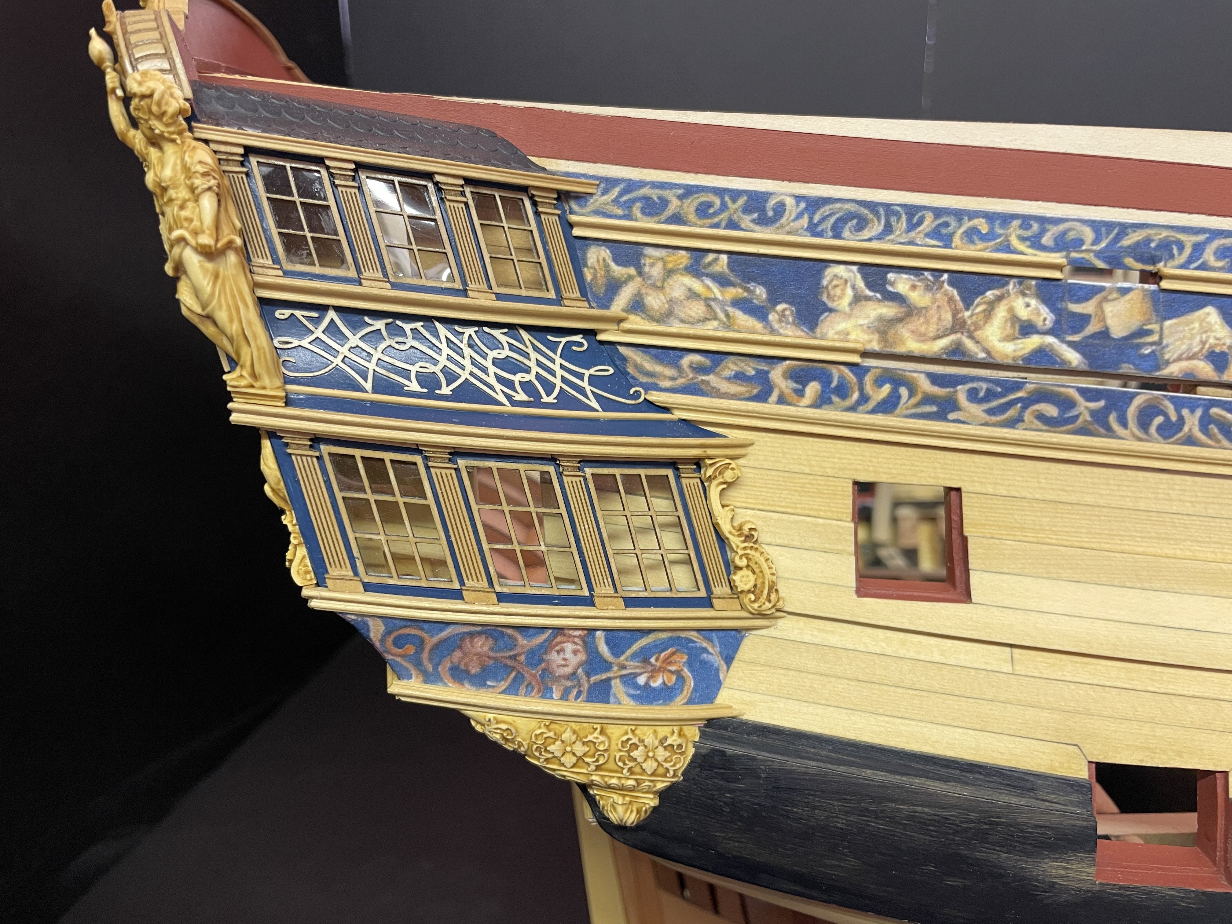
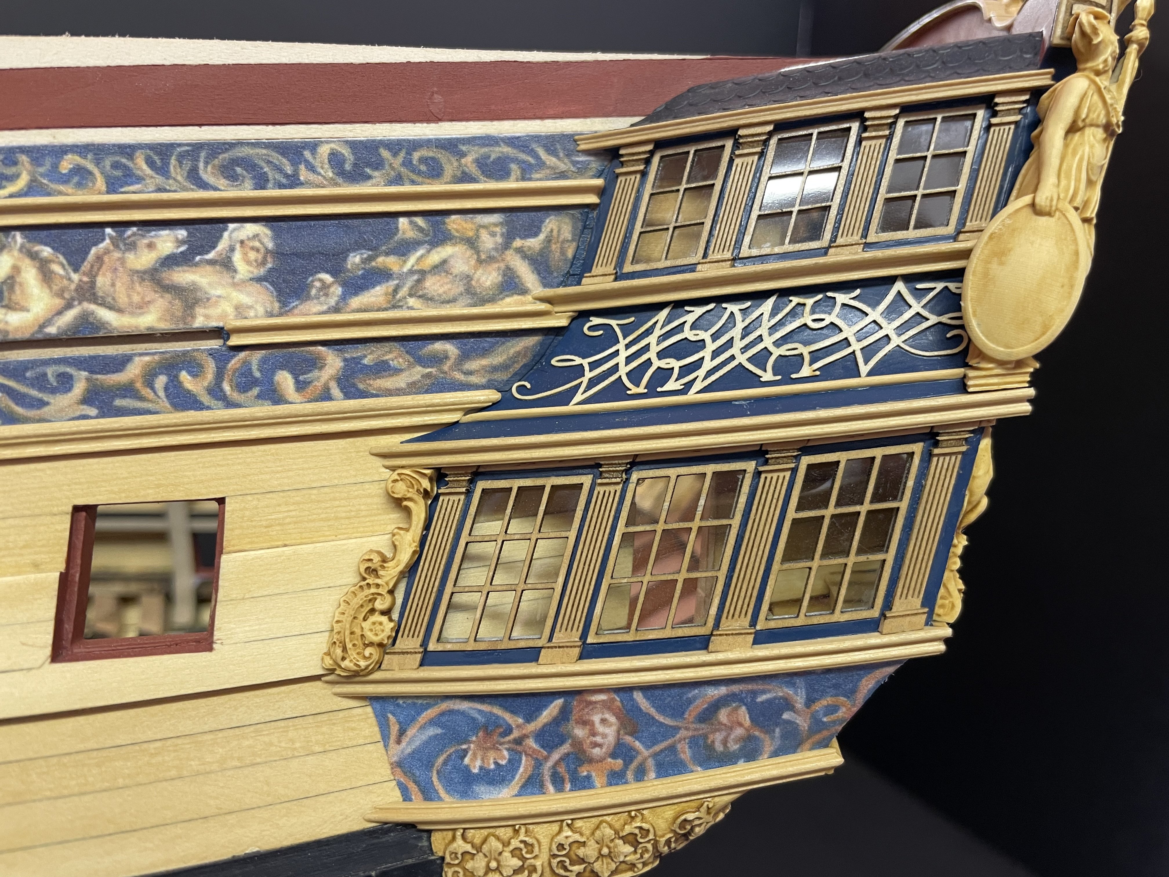
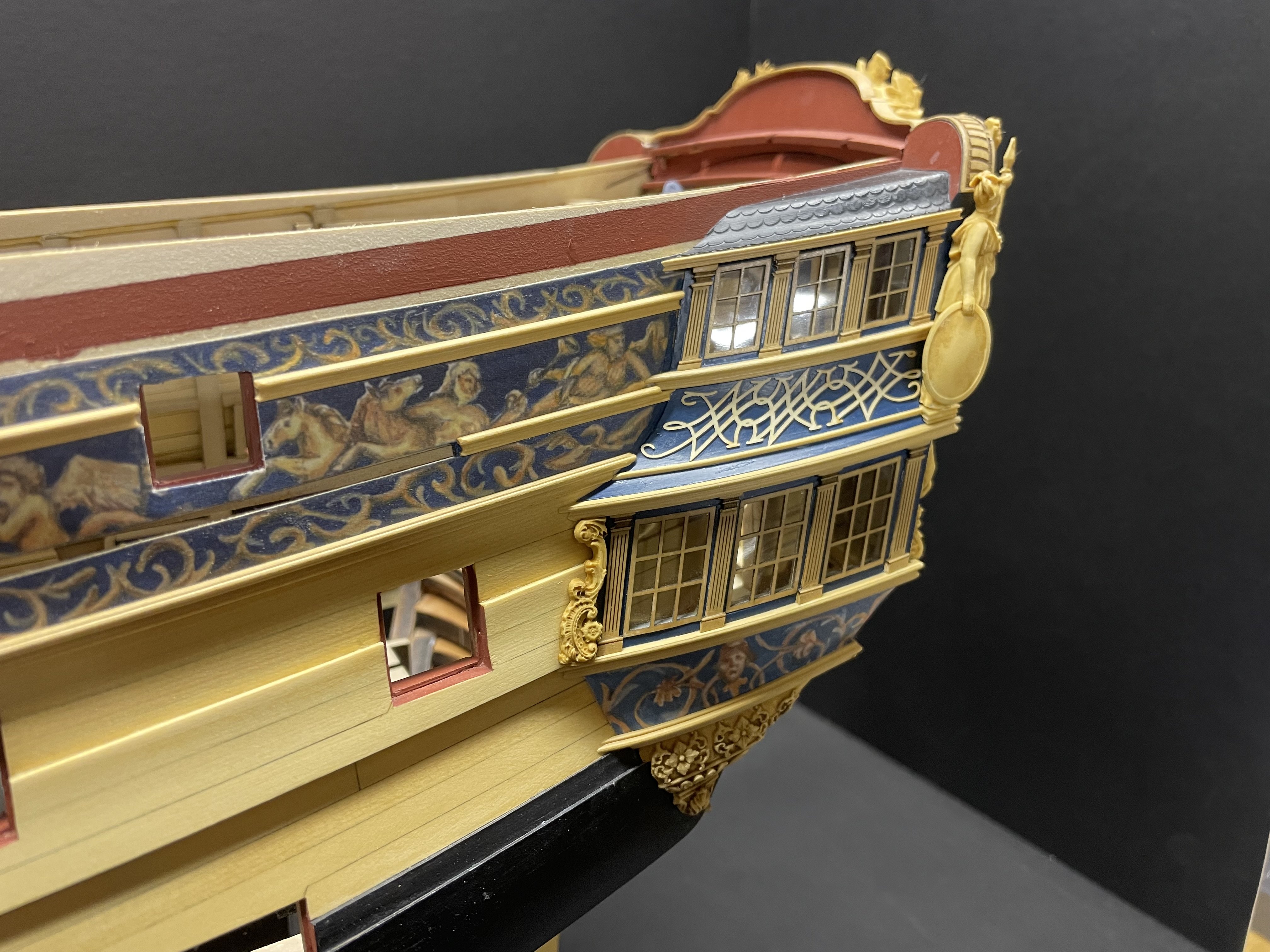
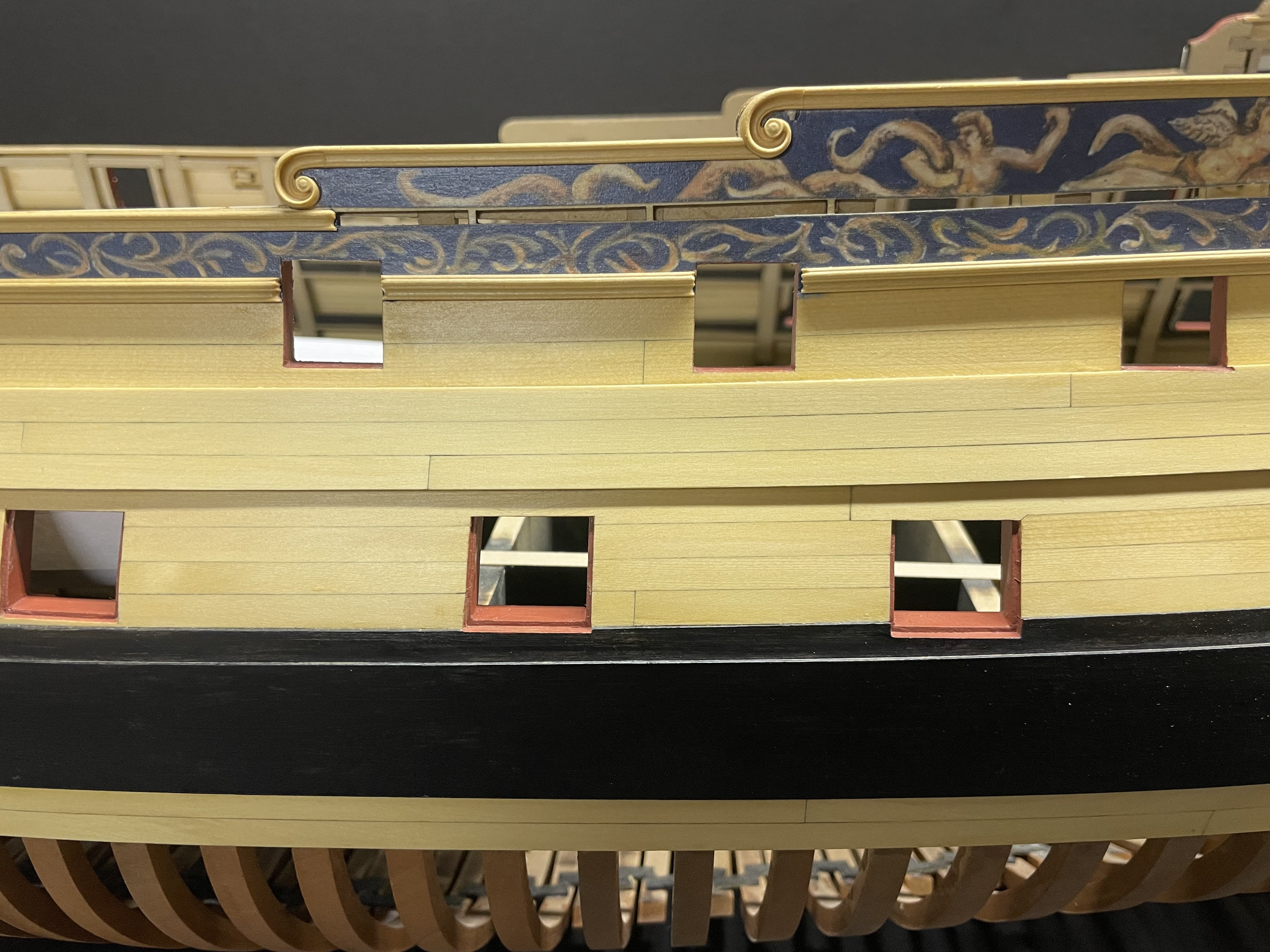
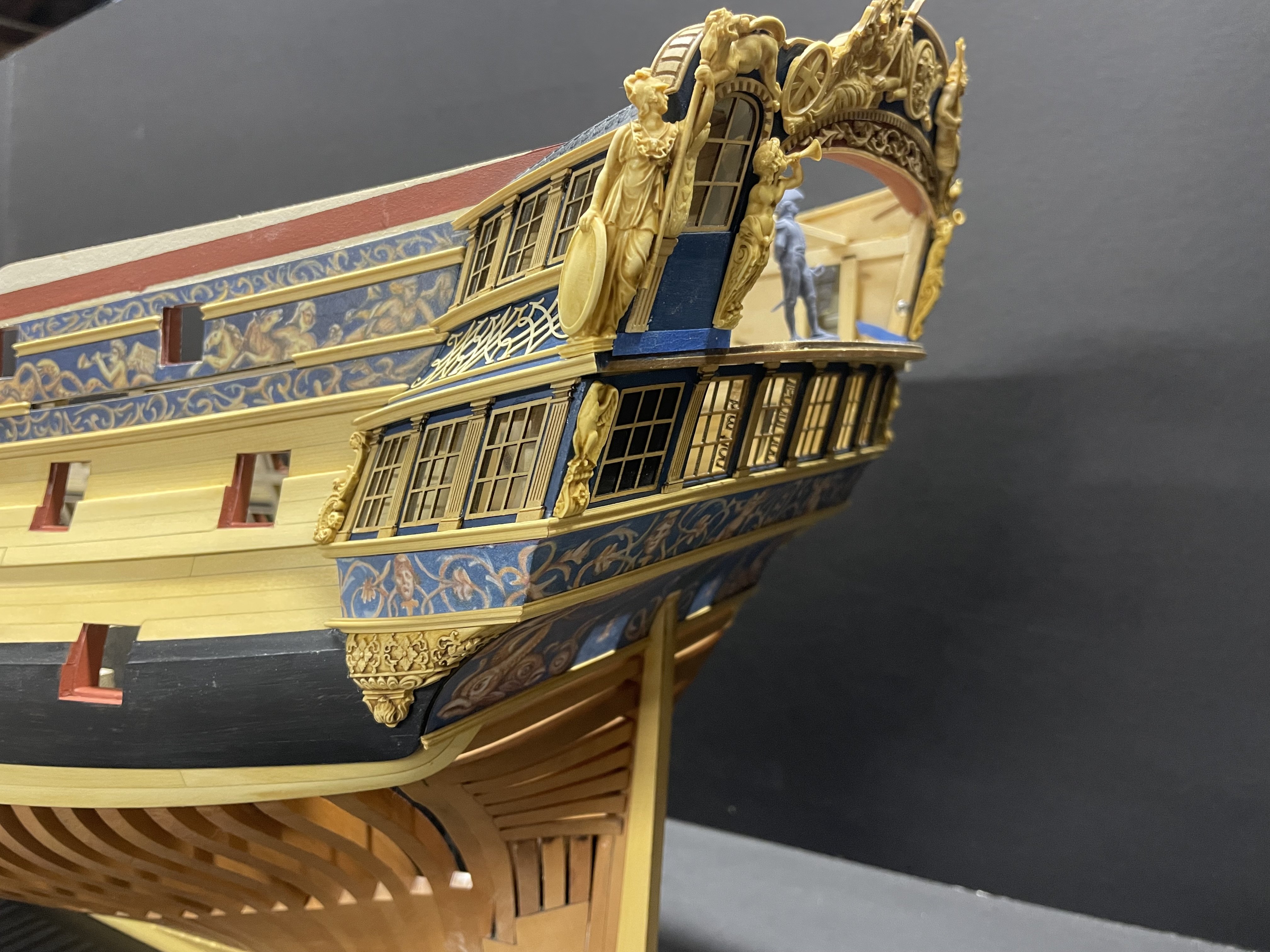
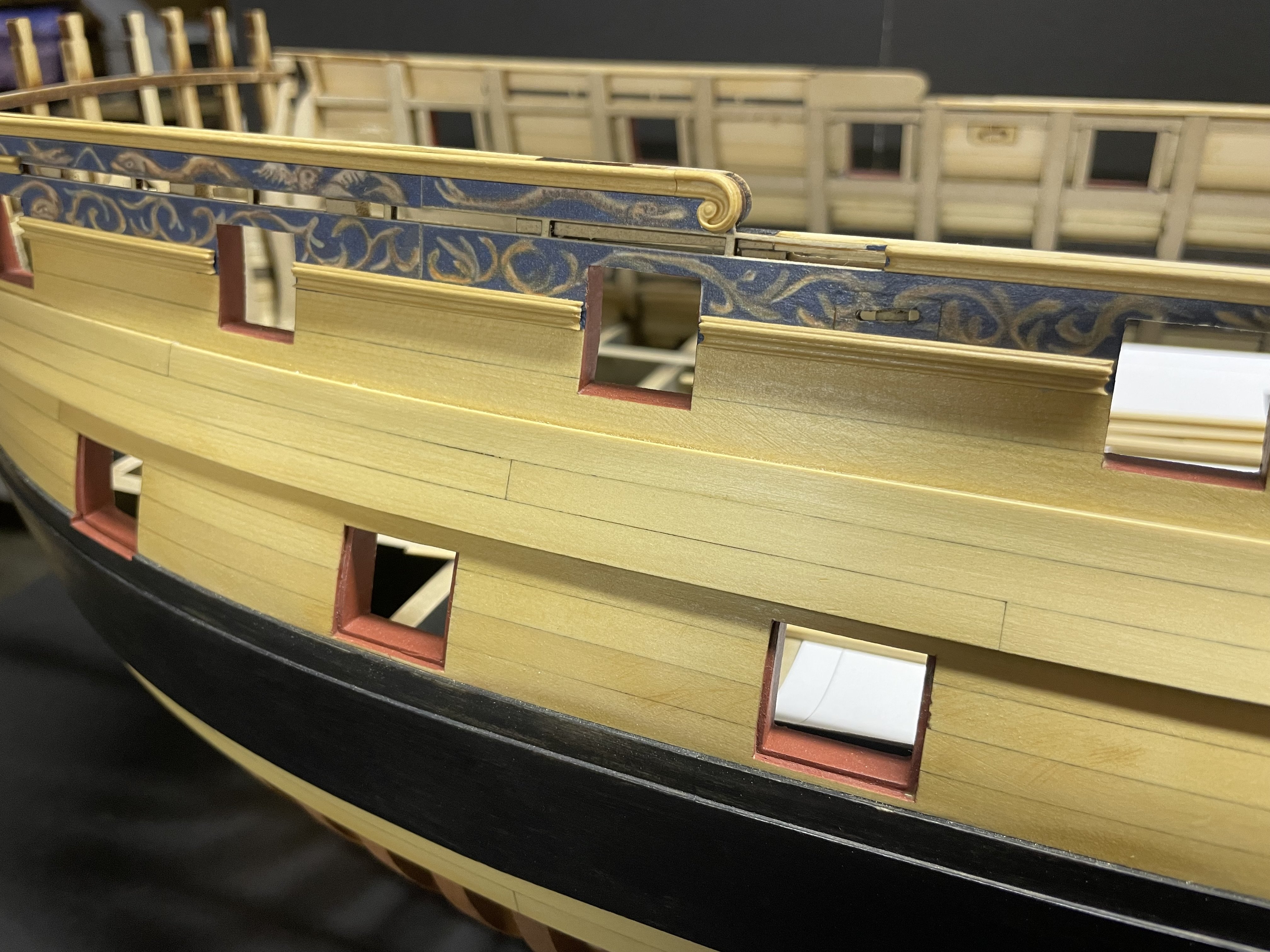
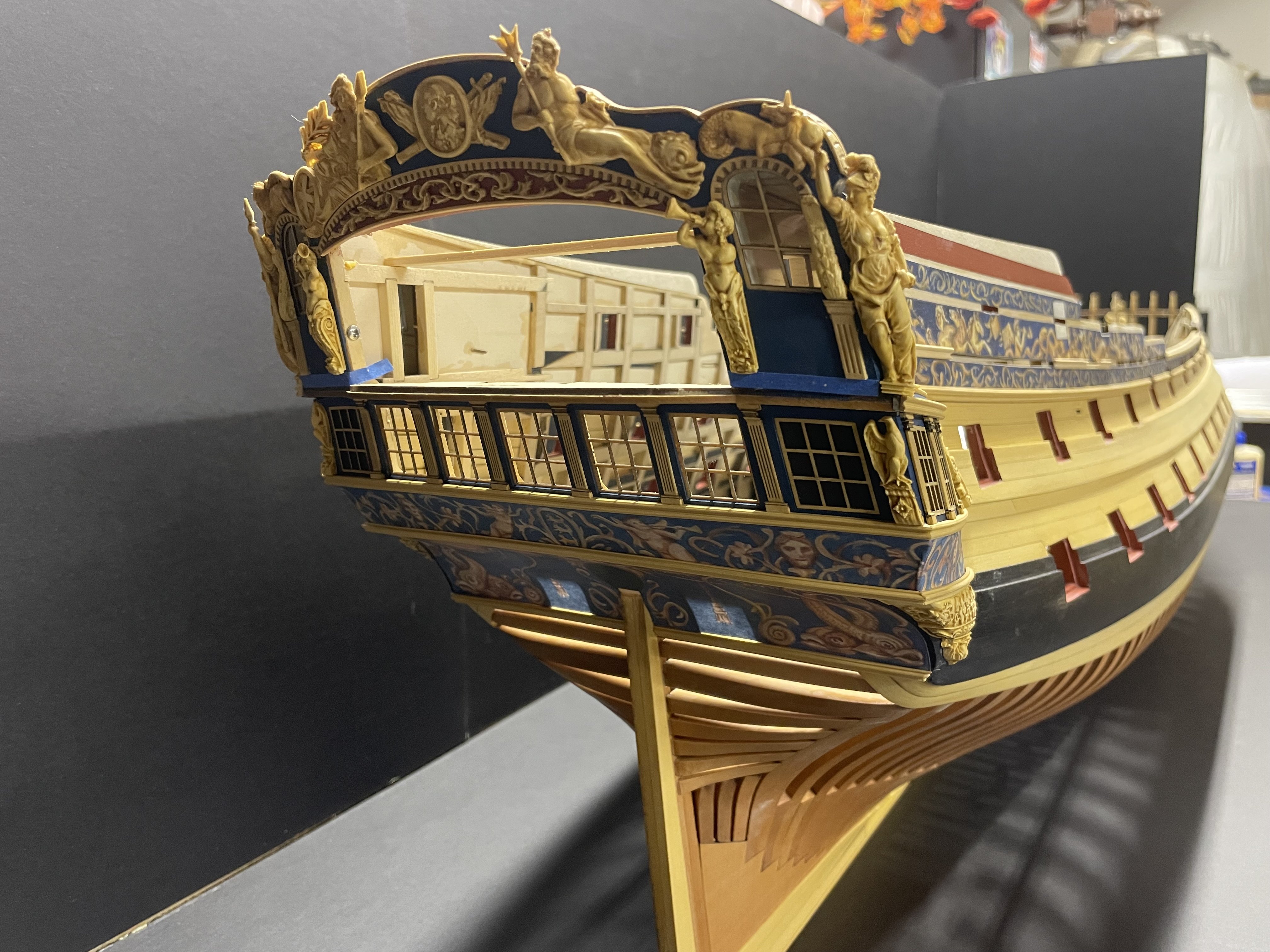
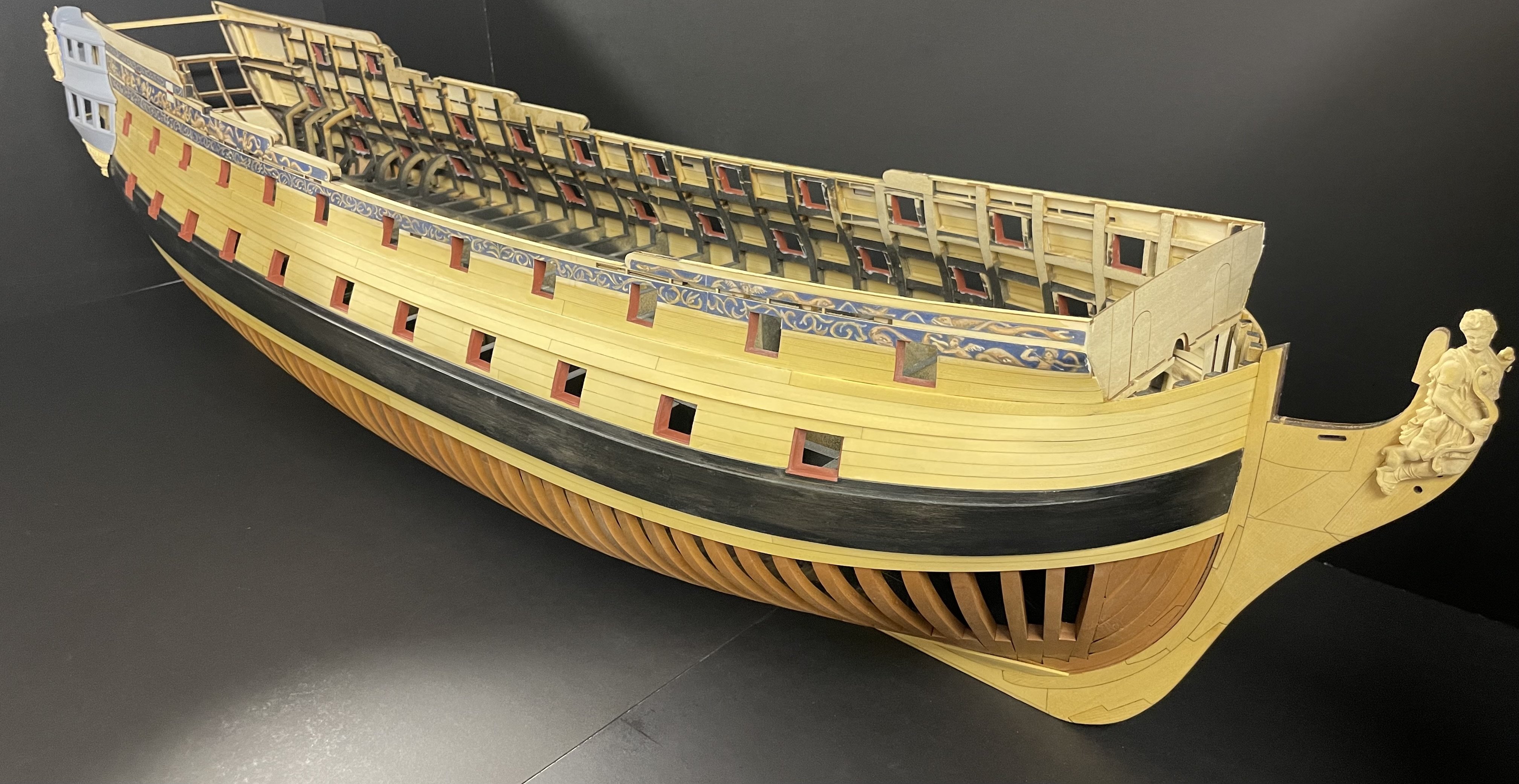
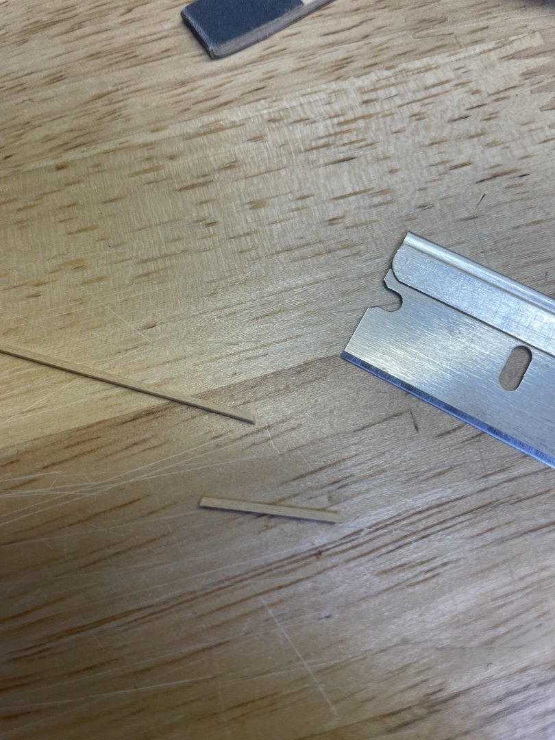
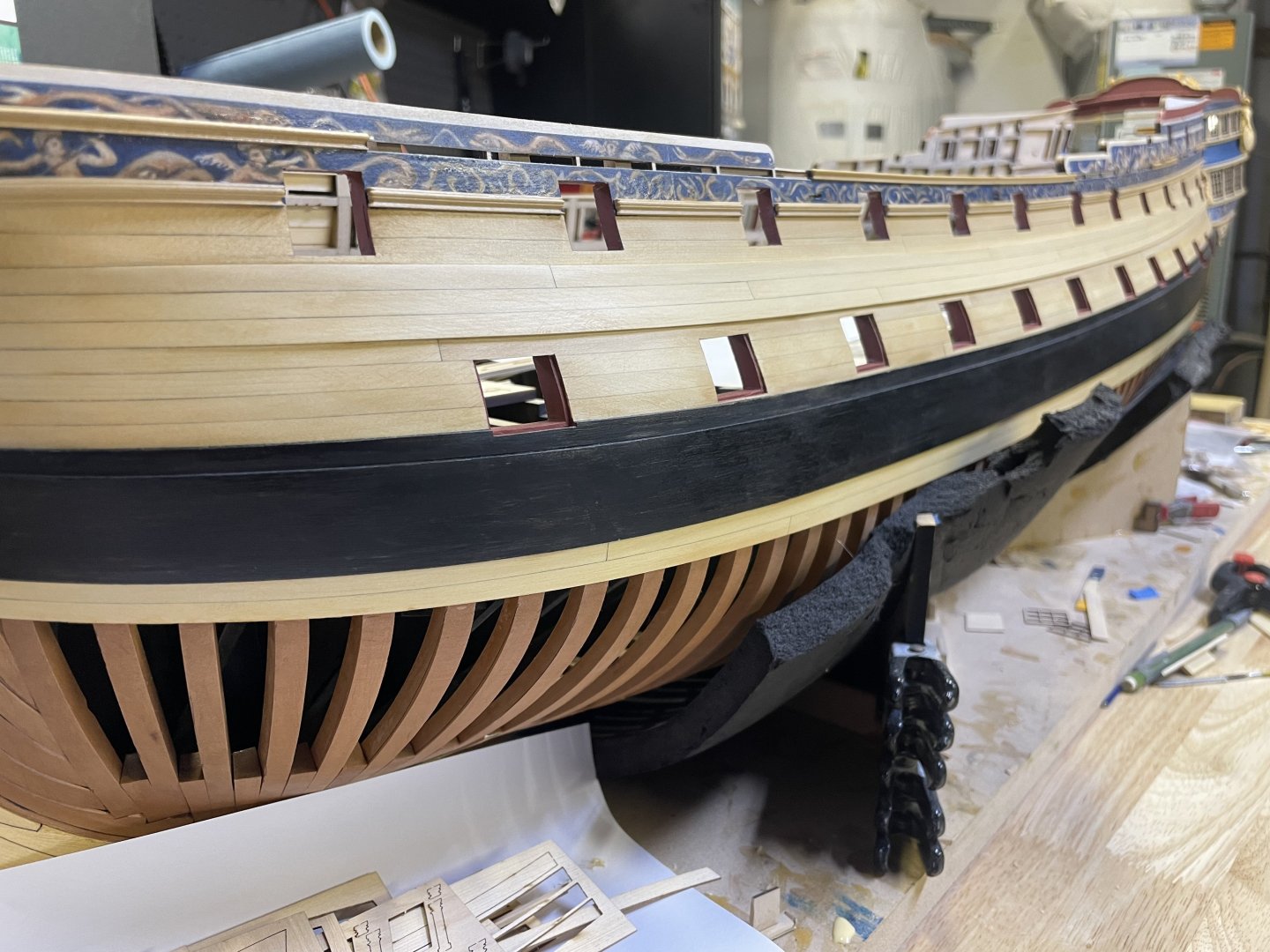
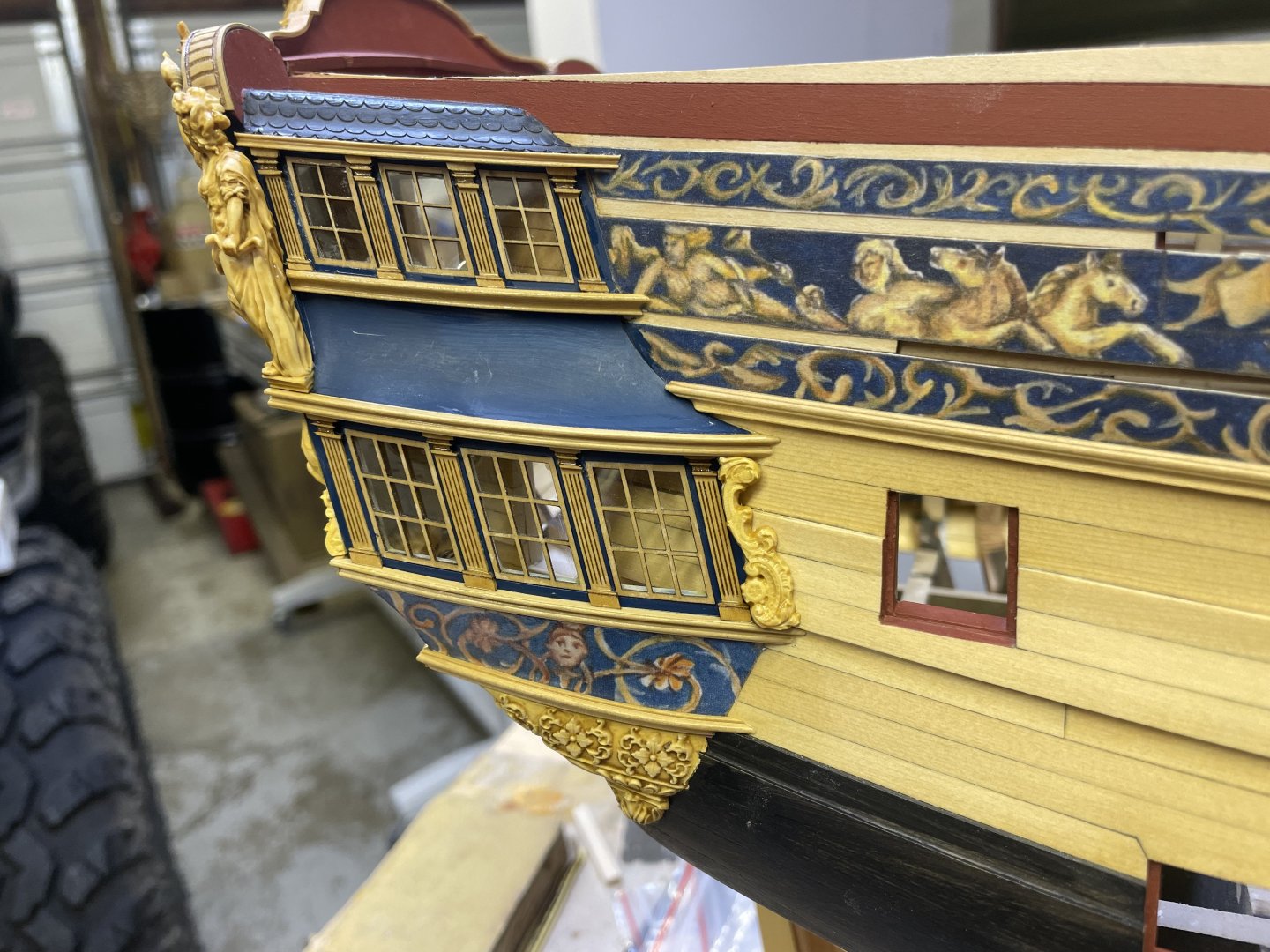
Chapter 3 concluded. I finished up by adding the small boxwood strip (.040x.040”) on the upper edge of the lower QG roof. These go between the columns and above the windows. Will begin chapter 4 in march which will be the main gundeck and fittings as well as spirketting for that level and I’m thinking possibly gun port doors.


-
Thank you Glenn. would definitely love to see you build one eventually.
-
That looks really good Steve. I’d use a matte clear coat like Chuck recommends. I noticed that the dye would come off on my hands when handling those parts during assembly. But very nice results!
-
I just updated my website I have 1 Portland kit 2 Winnie ch 1 1 Winnie ch 2 2 Winnie starters 2 capstans working on more
-
Hey guys, Im going to be winding down at the shop today as I have to get back to work on Friday (I still have to maintain a real job), so not much production for 6 weeks. As of today I’ll have another Portland kit up (they take about 1.5-2 days to produce), I’m also going to try and crank out some Winnie chapters as well as a couple capstans if possible. I’ll be available while away and I’ll keep the store open but I won’t be making anything until I return in early march. JJ
-
Thank you Kenny, that was my goal from the beginning when I designed them. I think it worked.
-
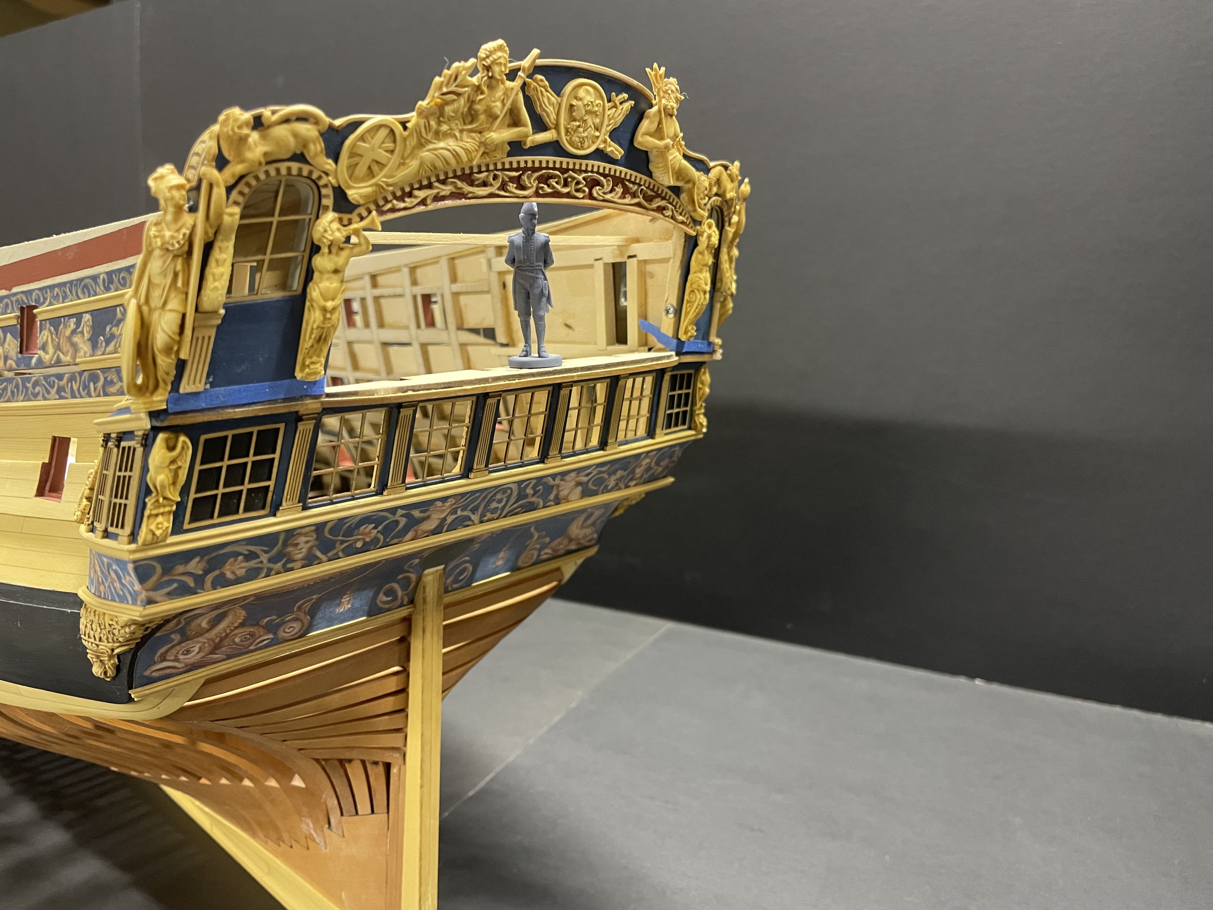
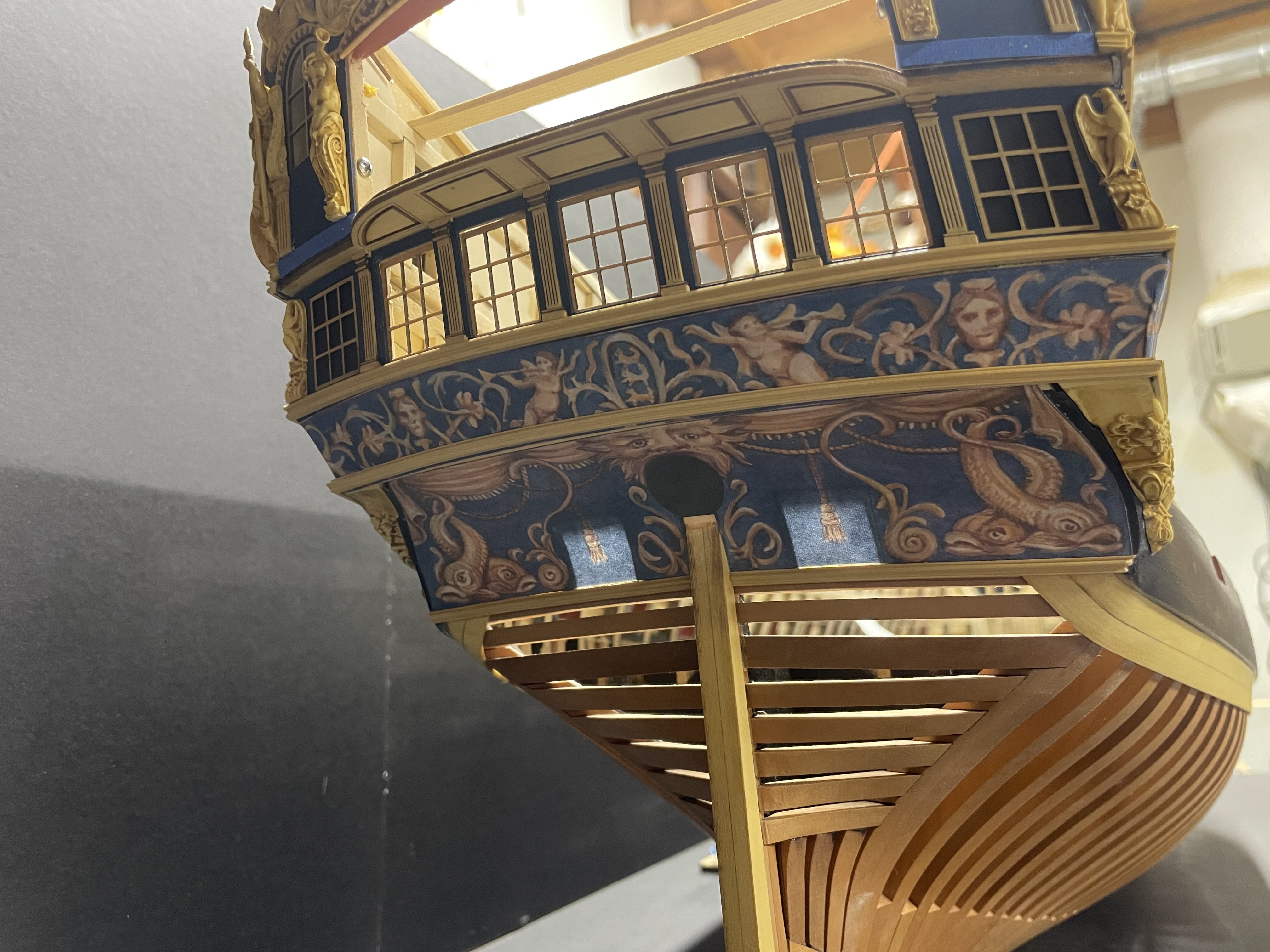
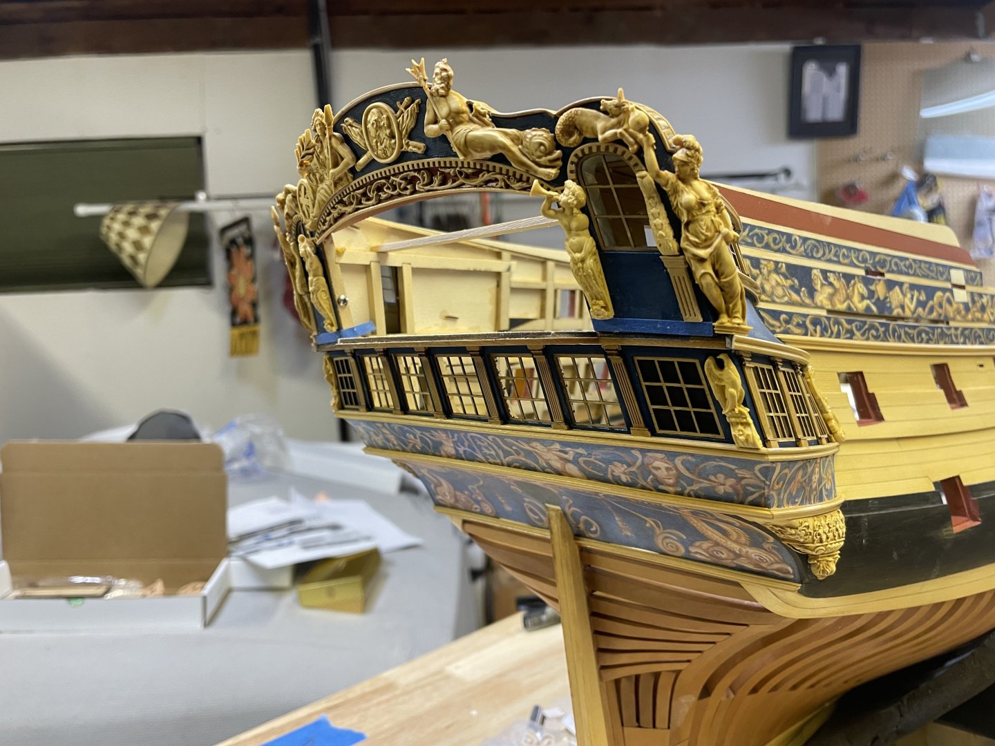
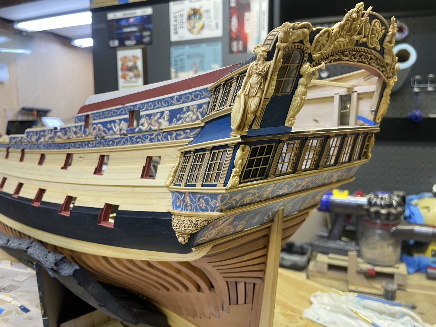
Almost finished with Ch 3. Need to add some strips to the QGs, a smaller frieze on the QG roofline and the stbd side upper molding and scrolls.


- 416 replies
-
- 27
-
-
-
Nicely done Steve. That looks really good!
-
Thanks Guys. It’s getting there. Gary, if there was ever a green light for ship modeling being displayed in the living room, Coming from the admiral that was certainly the best comment one could ever hope for!
-
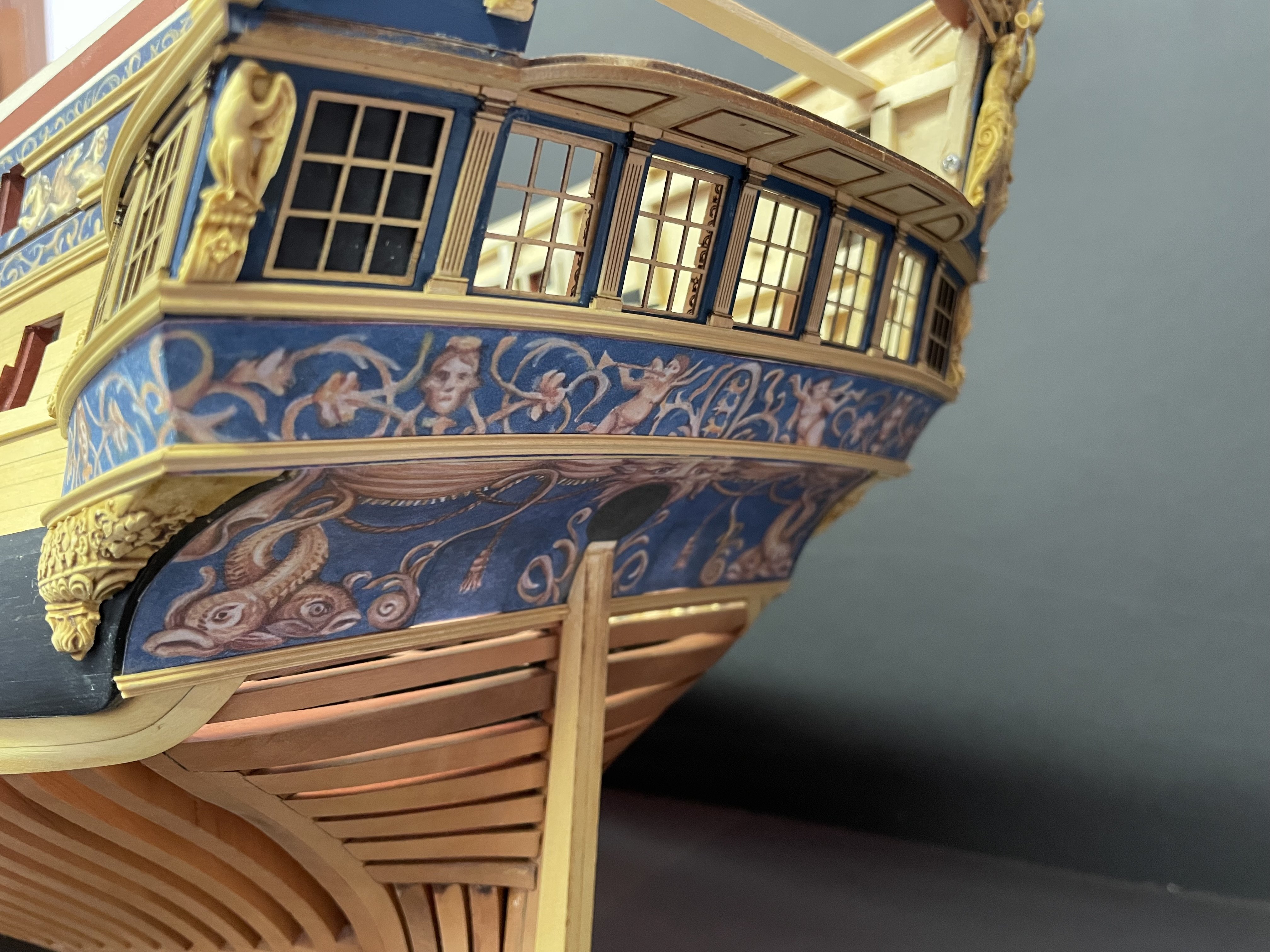
Few more Portland updates. I’m getting closer to finishing the QG’s. tomorrow I’m going to work on the lower QG frieze work that goes on the lower roof along with the thin strip of molding, also i have some boxwood scrolls to add! Should be a fun one. JJ
- 416 replies
-
- 27
-
-
-
Thank you Kenny. They are almost complete. Still some components to design and add. Updates soon.
-
Lovely work at that scale!