HOLIDAY DONATION DRIVE - SUPPORT MSW - DO YOUR PART TO KEEP THIS GREAT FORUM GOING! (89 donations so far out of 49,000 members - C'mon guys!)
×


Stuntflyer
-
Posts
1,197 -
Joined
-
Last visited
Content Type
Profiles
Forums
Gallery
Events
Everything posted by Stuntflyer
-
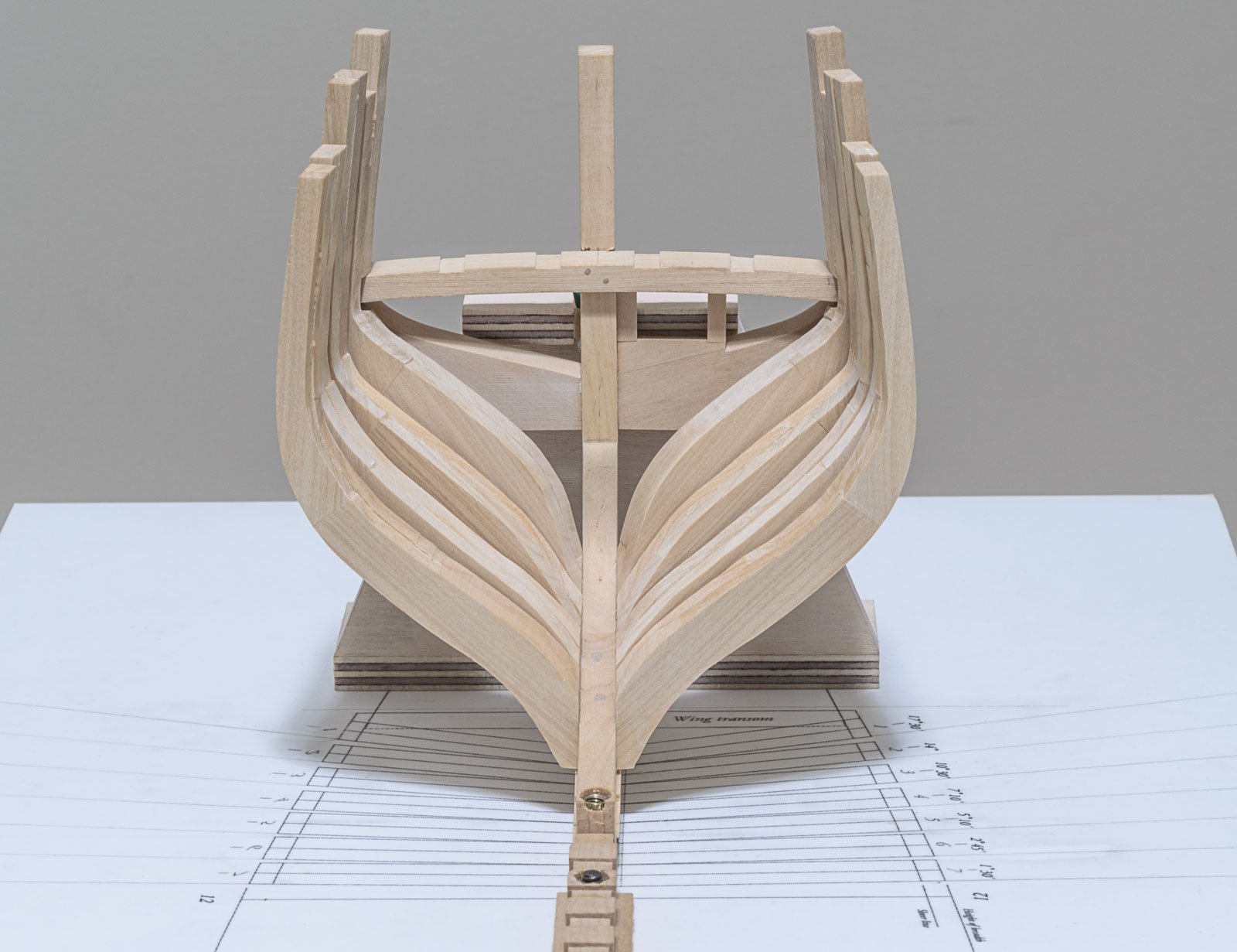
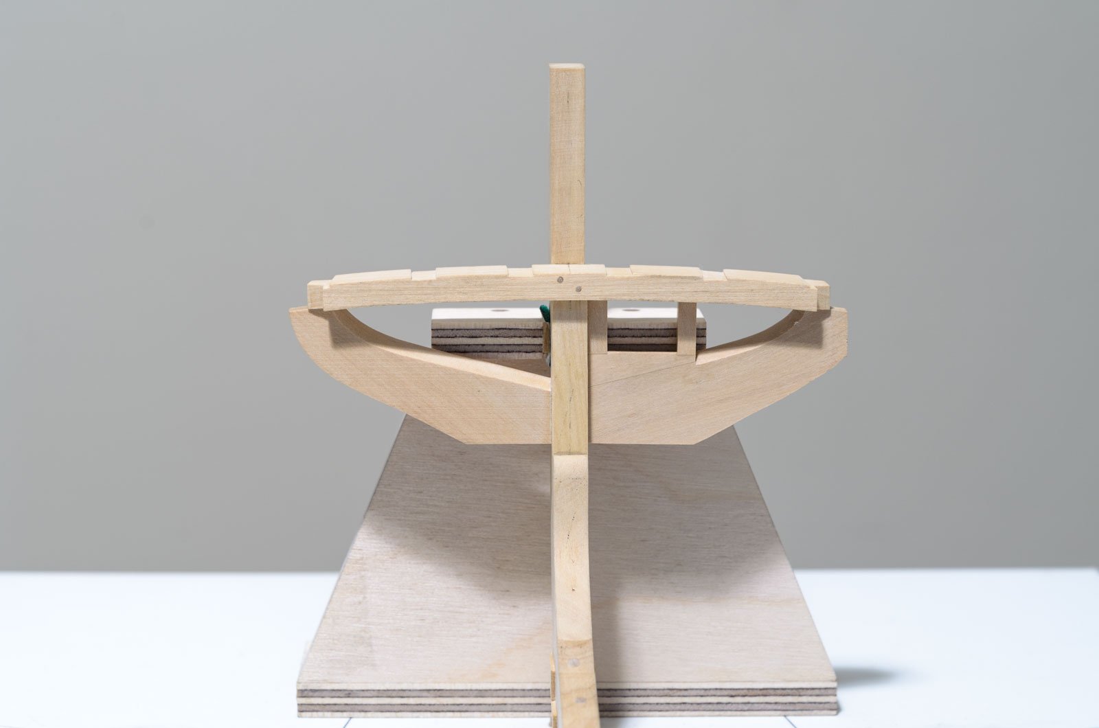
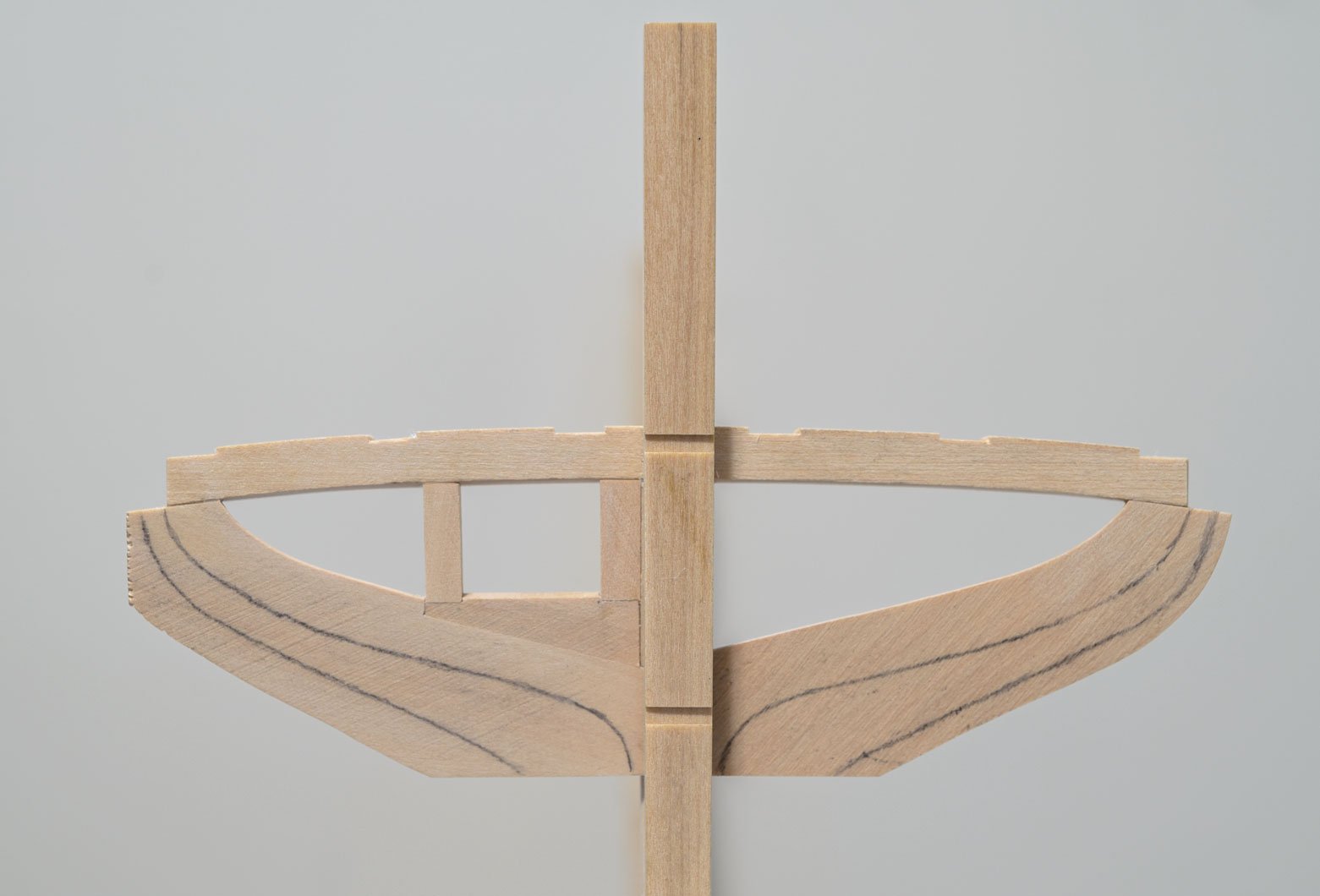
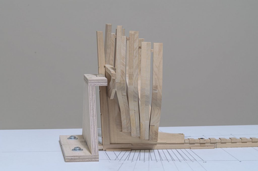
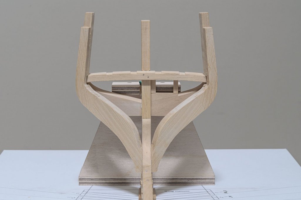
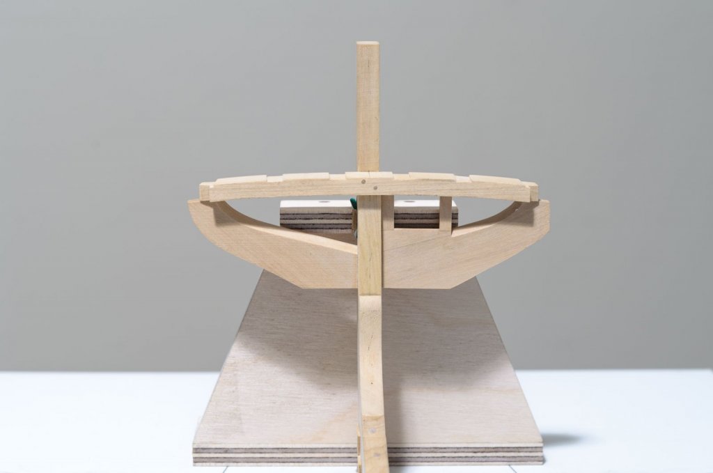
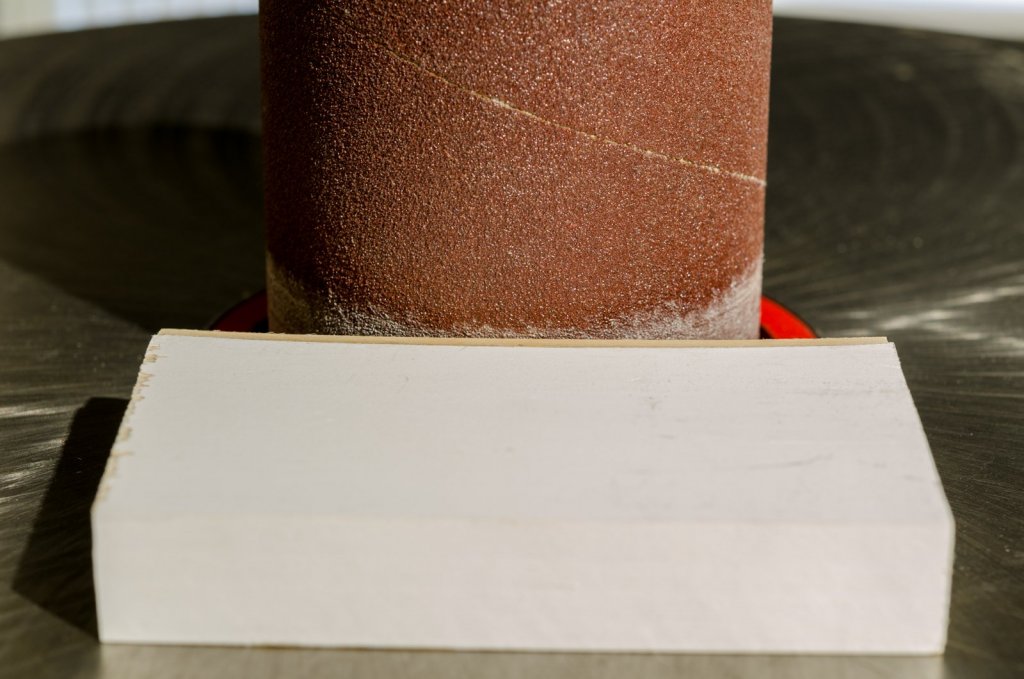
 I have completed an internal rough fairing of the first four aft cants. Lots and lots of filing, sanding, etc. This before and after photo should show just how much wood needed to be removed. The structure is quite strong with AC 1 glued to the wing transom and small spacers glued between the toptimbers. This allowed me to use chisels and coarse riffler files without fear of breakage. Mike
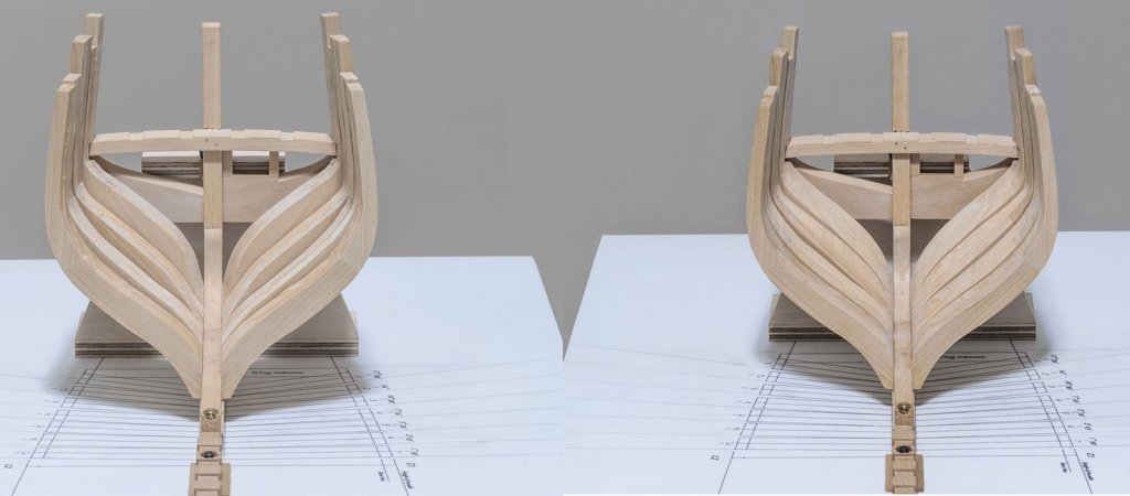
-
Chuck, I've seen your original Winnie first hand it's a beauty. I'm sure that Winnie "Version Two" will be every bit as nice and probably top it. I'm looking forward to the build and also hearing about those design changes you plan on making. Your off to a great start! Mike
- 1,784 replies
-
- 11
-

-
- winchelsea
- Syren Ship Model Company
- (and 1 more)
-
Thanks guys! I appreciate the feedback. I'm waiting for a new riffler file to arrive to handle some of the inside fairing work. Meanwhile, frame making continues. Mike
-
Great stuff, Chuck! Always innovating. . Mike
- 269 replies
-
- 8
-
-
- Queen Anne Barge
- Syren Ship Model Company
- (and 1 more)
-
Thanks for the kind words, ken and for the "Likes"! I now have four of the seven aft cants completed, though I'm still developing my preferred method of making them. Before moving onto the remaining three, I need to do a rough fairing inside the hull. There is a lot of wood to remove, especially on the two aft most cants. The outside of the hull will not be sanded or faired until all the framing is completed. Gonna be a while. Mike

-
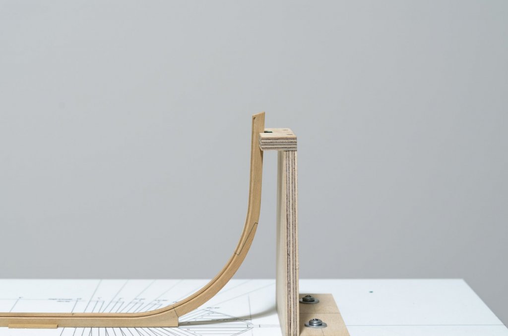
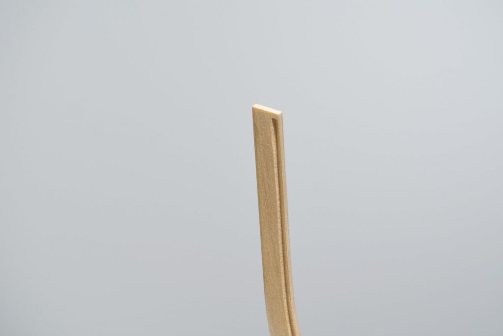
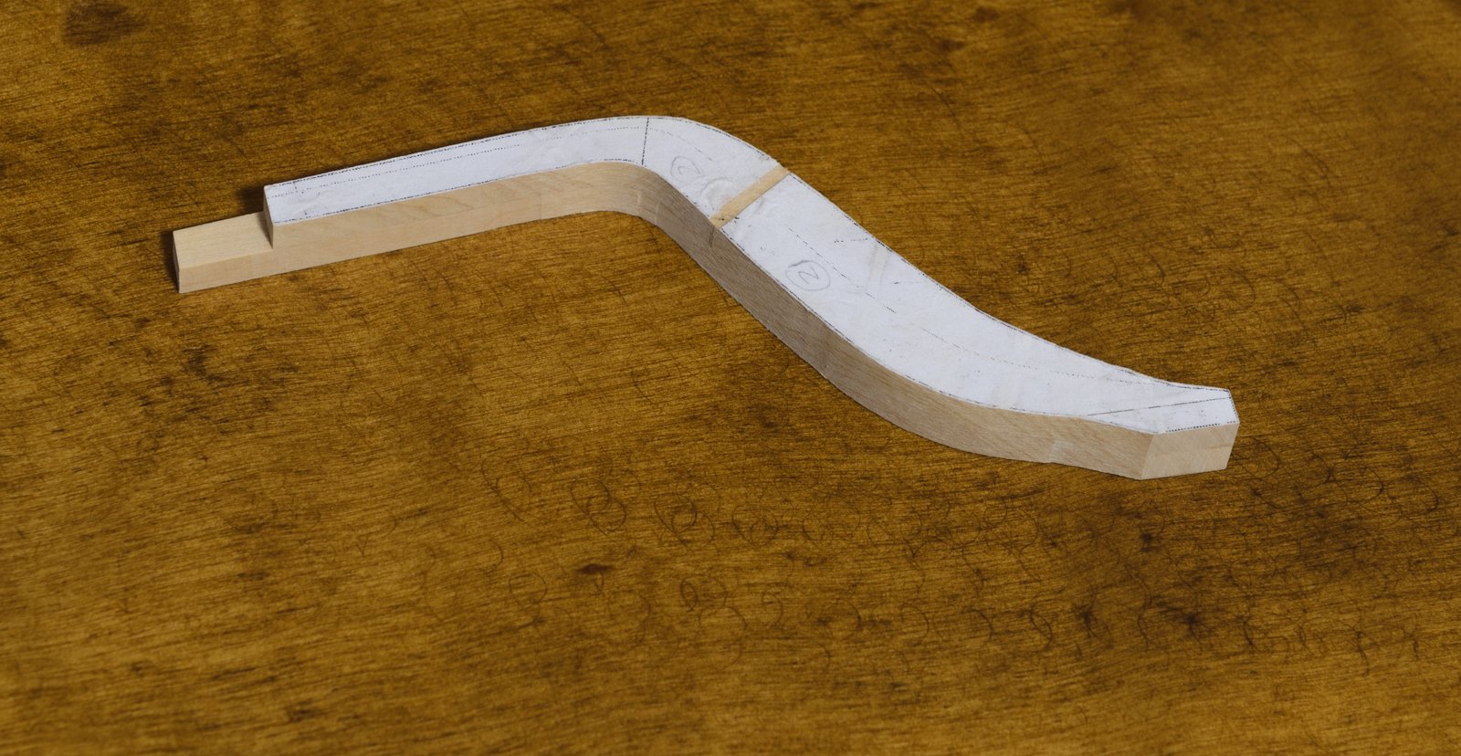
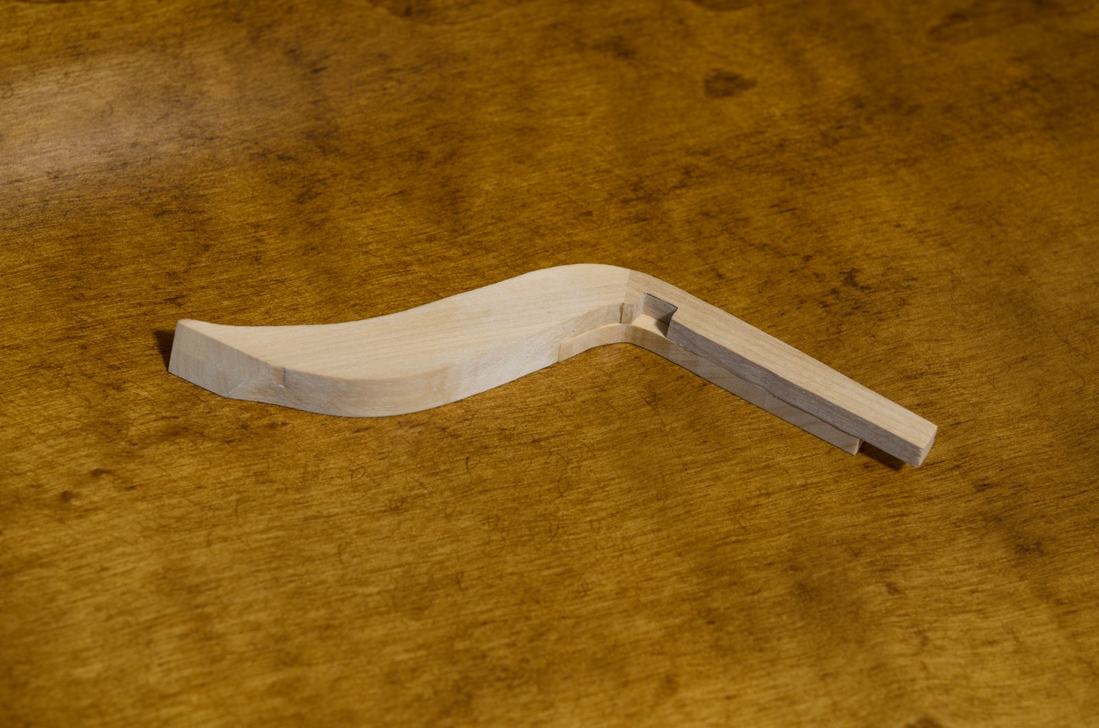
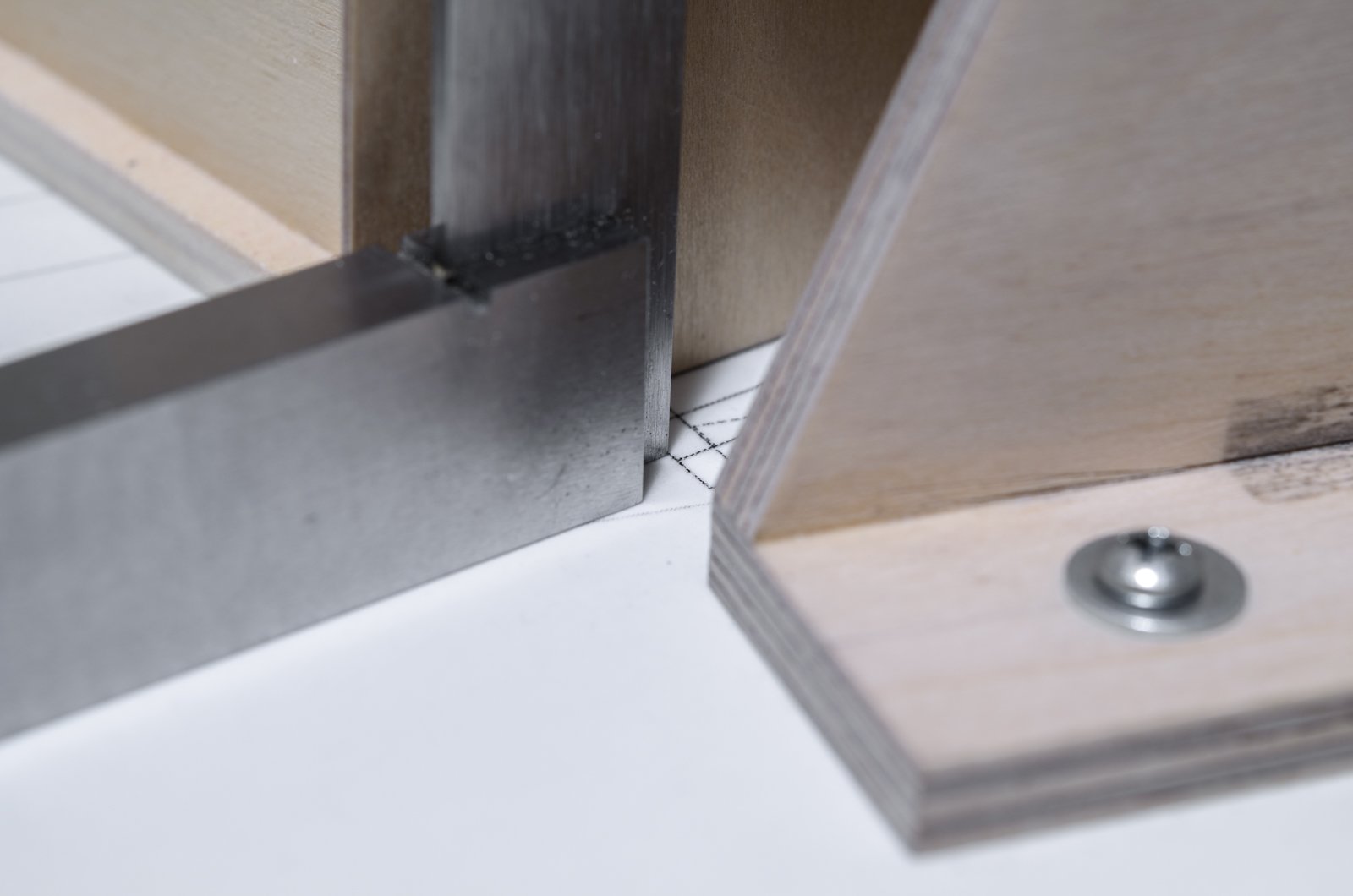
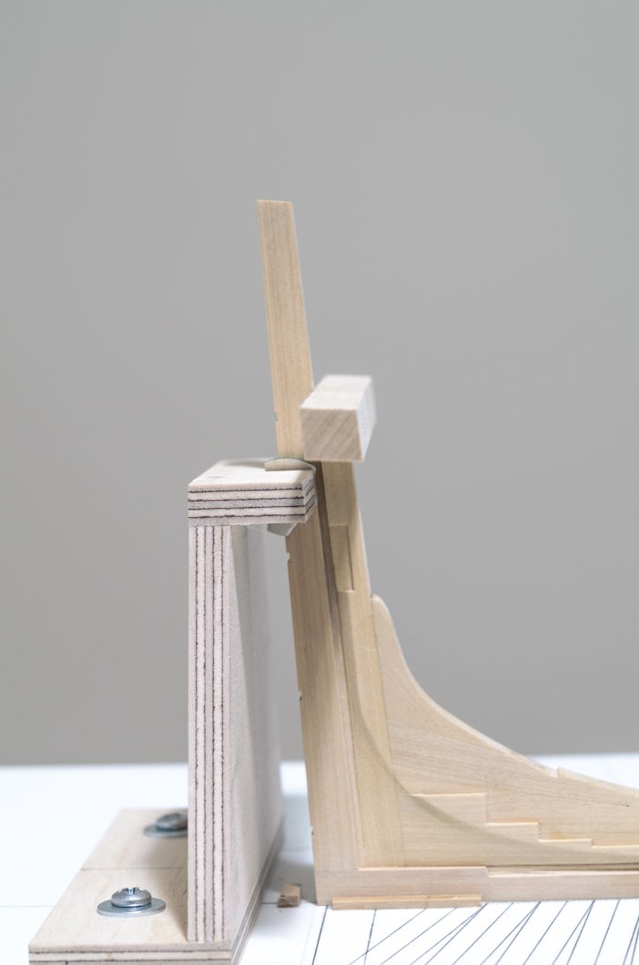
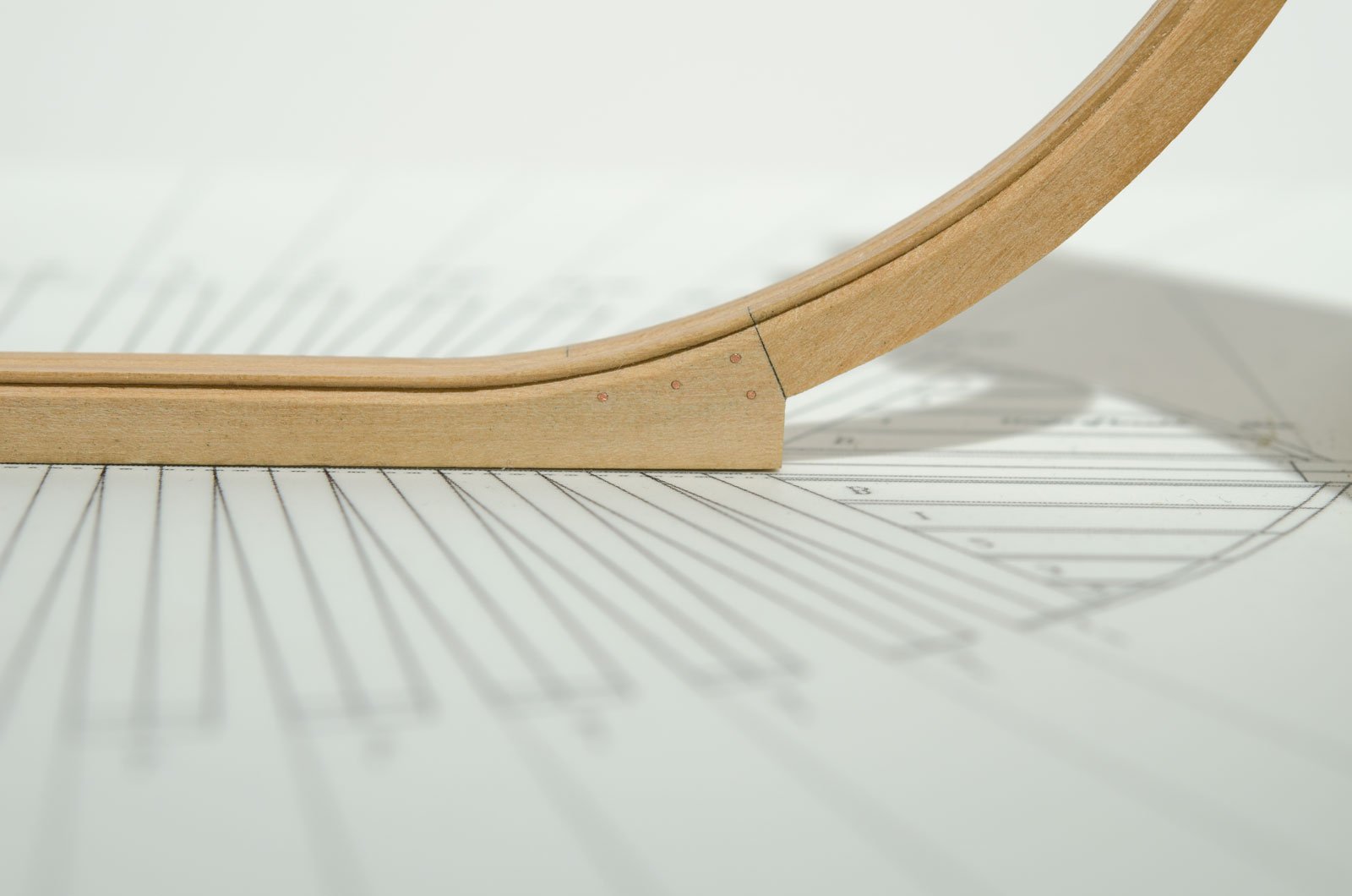
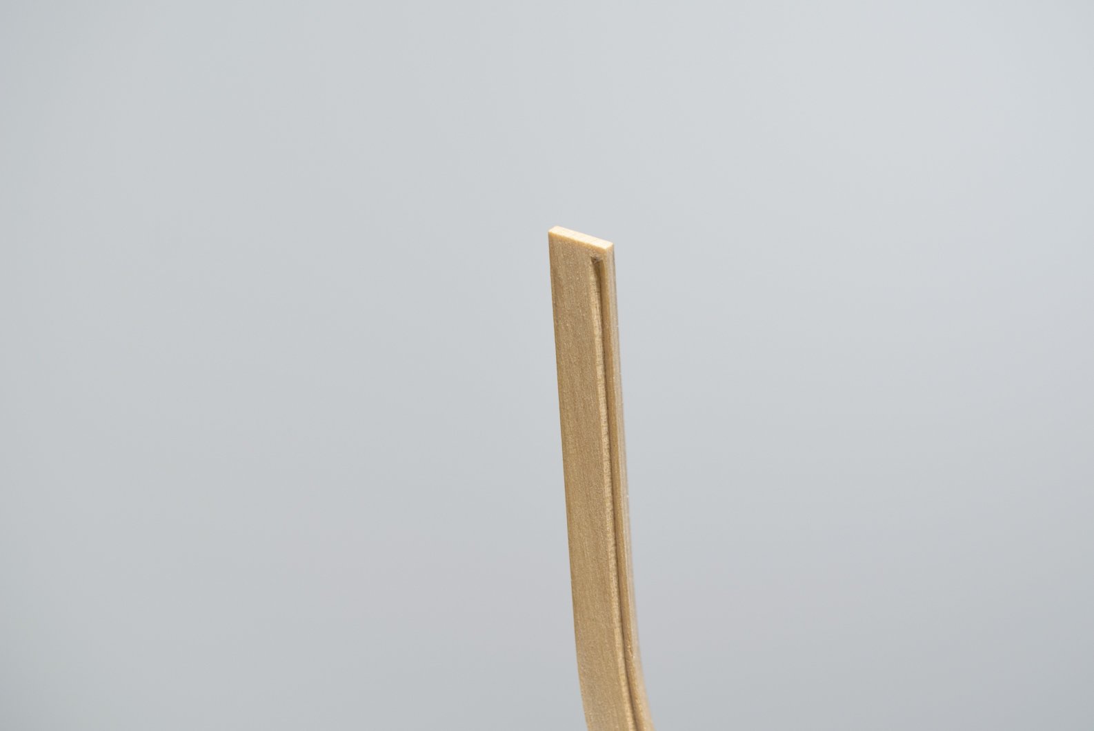
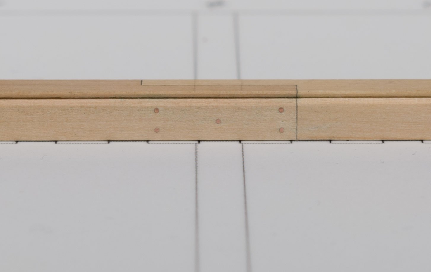
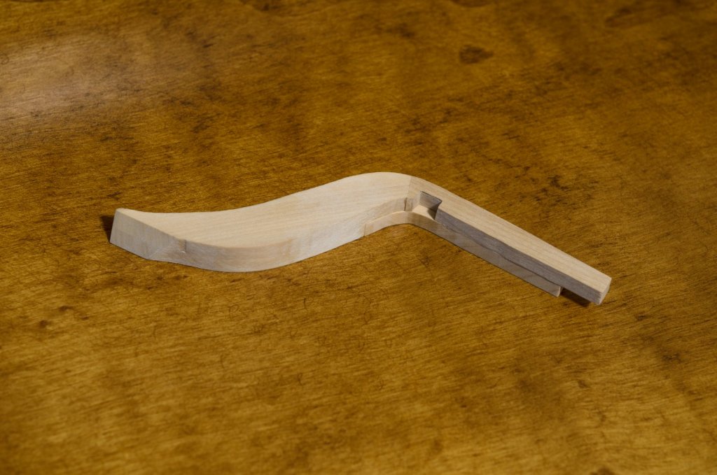
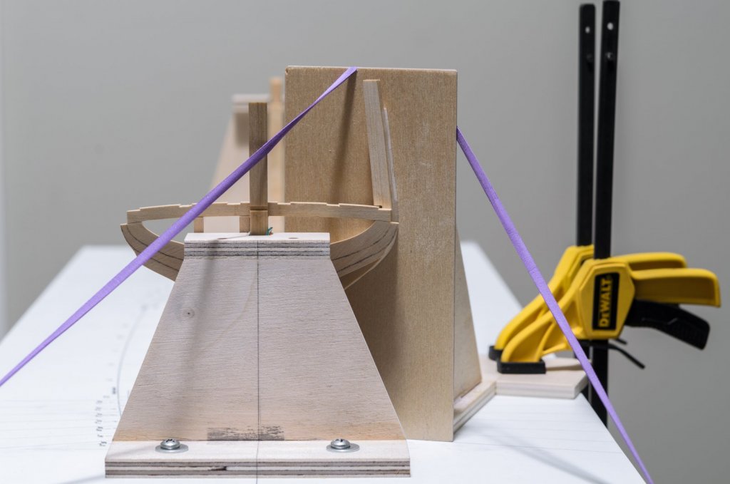
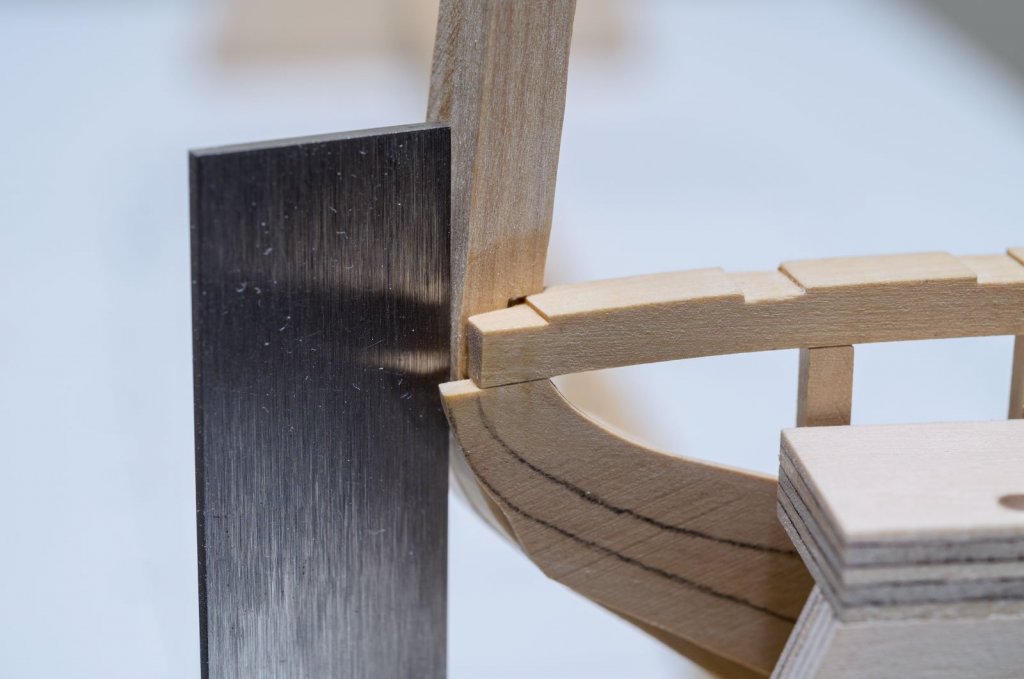
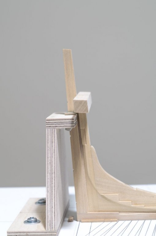
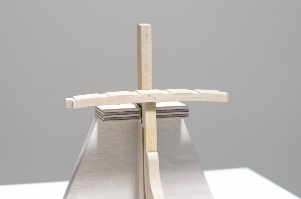
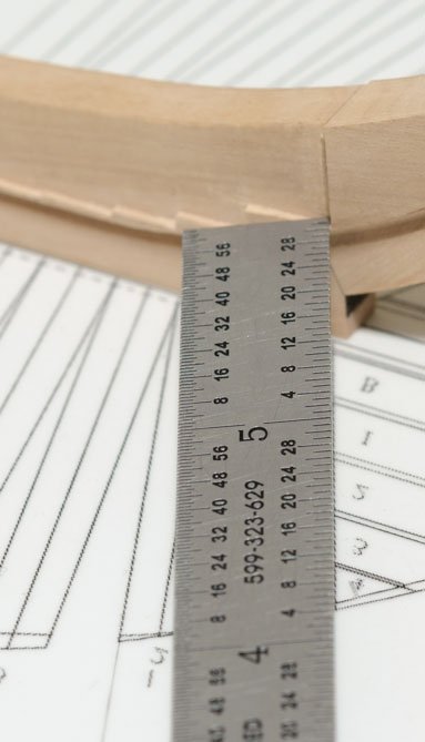
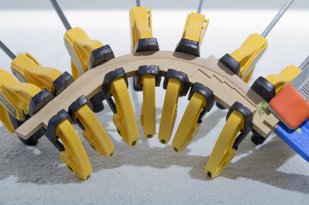
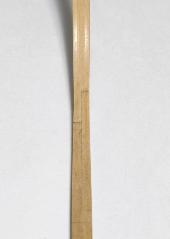
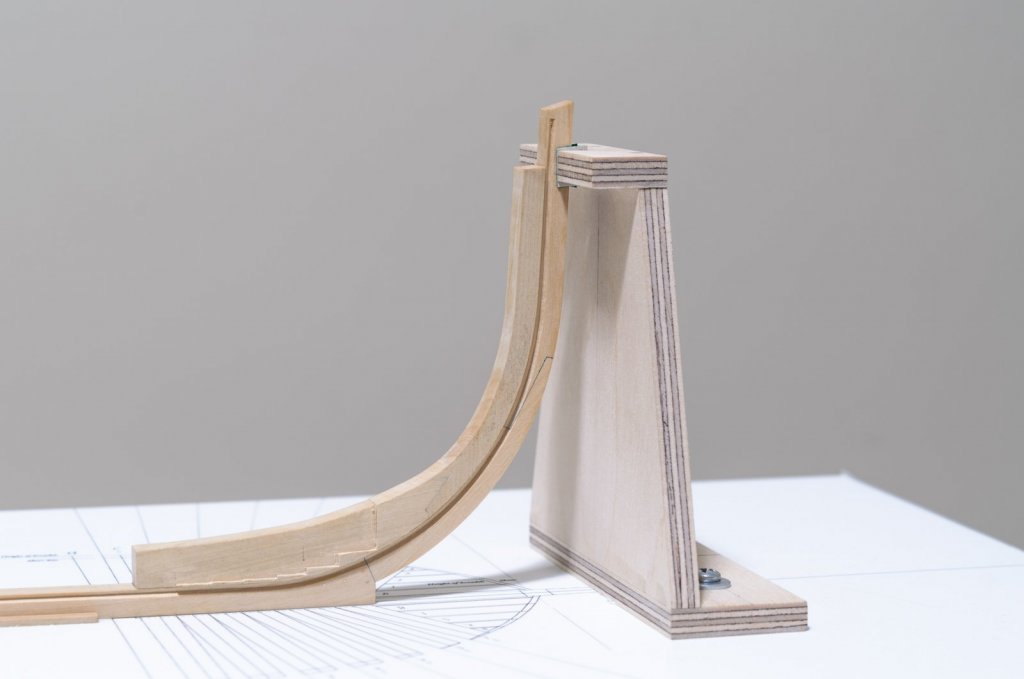
With the the stern framing completed, I'm ready to work on the 7 aft cant frames. They are all doubled with no scarph joints or chocks. Basically sections glued together with butt joints. To be safe, all of the sections are cut slightly past the line and double checked over the drawing before gluing them together. Here I have completed the assembly of aft cant No.1 (AC 1) port side. In order for it to line up properly, a score must be made on the aft side where it meets the wing transom. This is because it has not been faired yet and must be moved in a bit at the top. A bevel has been created where it will sit against the deadwood. My disc sander has an accurate adjustable table that makes this an easy process. Installing the frames was done with the aid of a 90° jig that was made from plywood. Clamps and a rubber band hold it securely in place. The score in the frame allows for the proper alignment with the drawing. Mike


-
Thank you all for your comments and "Likes" Continuing on with the stern framing requires that the fashion pieces be added. The feet of these pieces sit in the scores that were made earlier to the inner post. They are not the same shape since the one on the port side has a "timber loading port". A small filler piece was added to create the lower sill. Two vertical posts were added to define sides of the port. The angle where the pieces join the wing transom needed to be established and there was some beveling done on the inner face. I had fun making them! I left a generous amount of wood outside for the fairing later. Mike
-
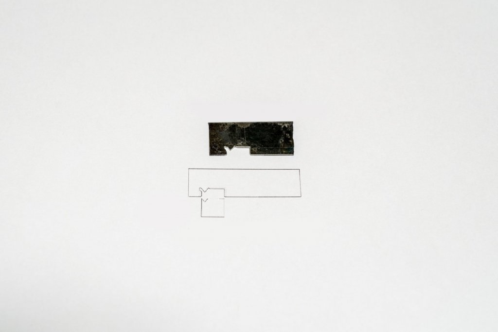
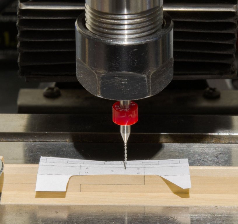
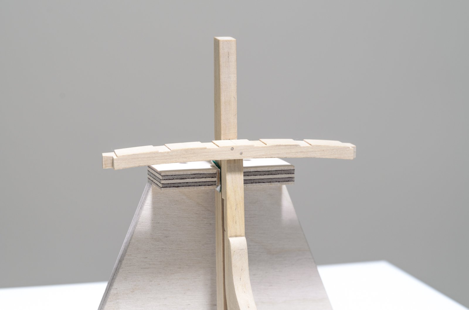
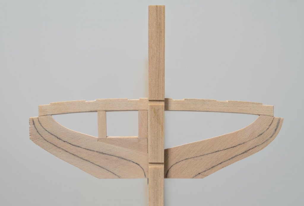
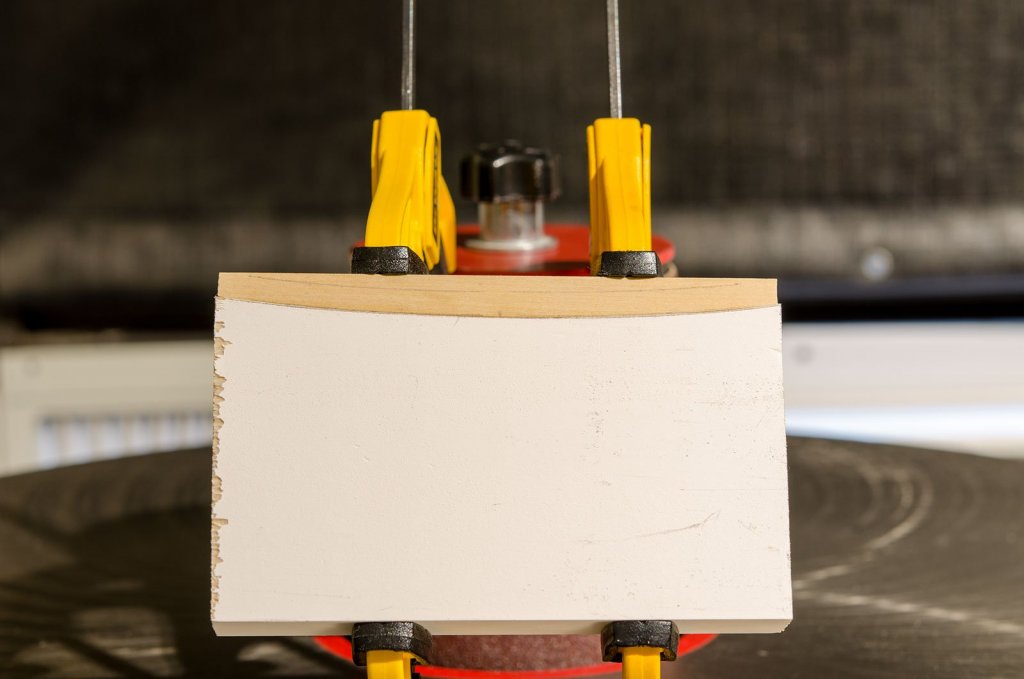
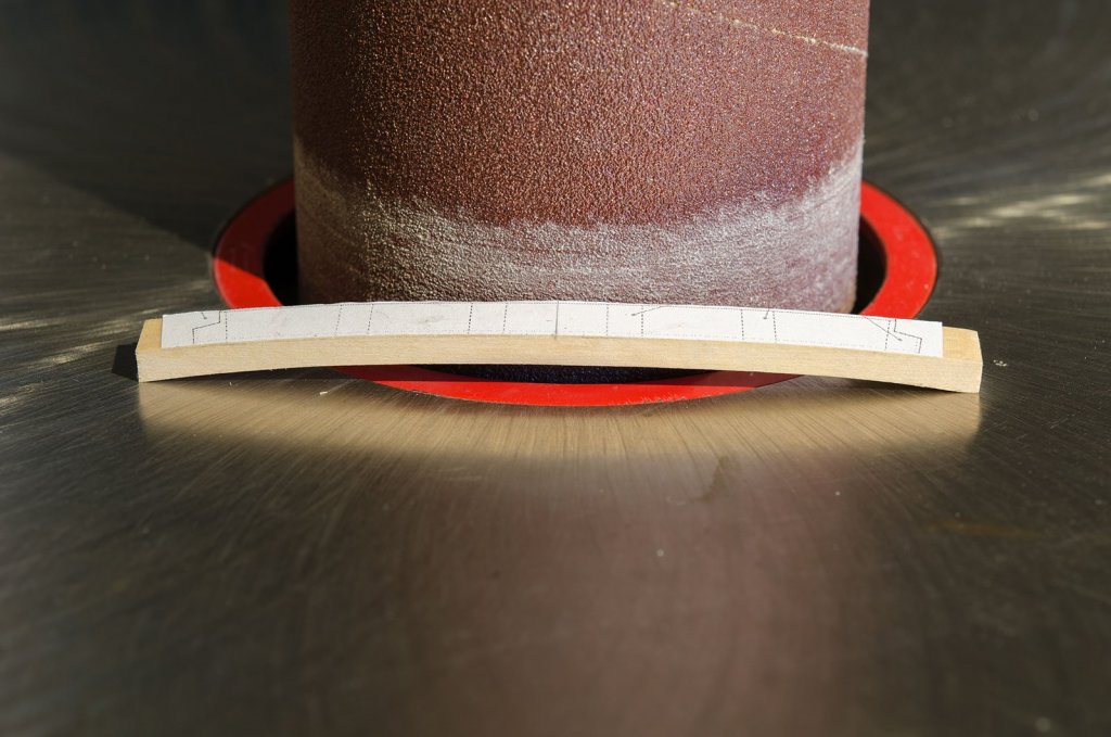
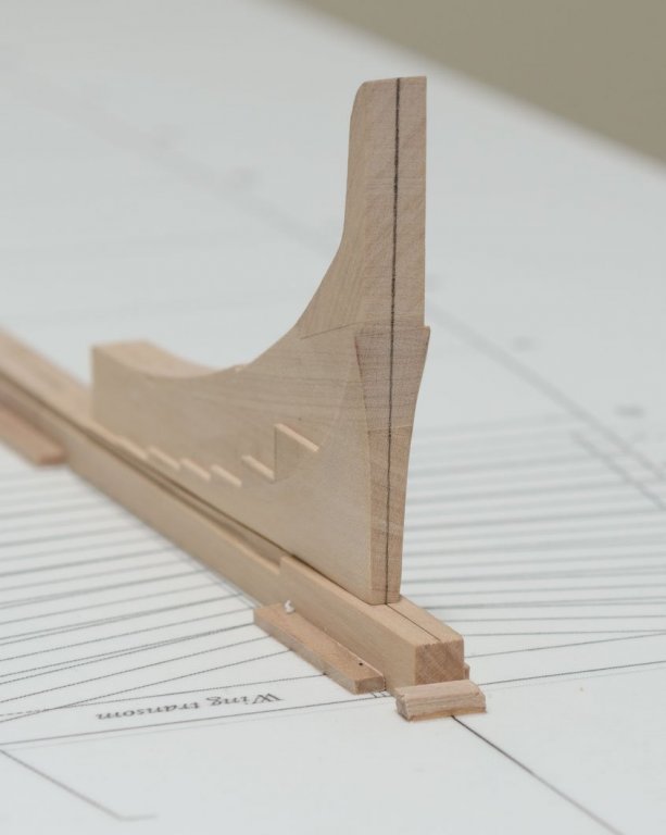
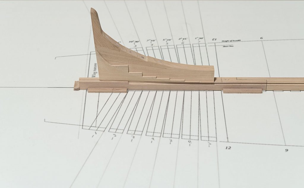
Work continues with the making of the transom wing. The initial shape can be seen while sitting on the inner post. From here a curve on both sides needs to be created. The convex curve was done on the disc sander while handheld. For the concave curve, the wing was glued to a pine block with "Elmer's School Glue" and sanded with the spindle sander. After establishing the curve, a paper template was glued the the wing. Scores need to be cut for the counter timbers and cut-outs made for the first aft cant frames. Afterwards, the finished wing was glued and pinned to the inner post. Careful attention was given to insure proper alignment for both centering and the wings relationship to the building board. Mike
-
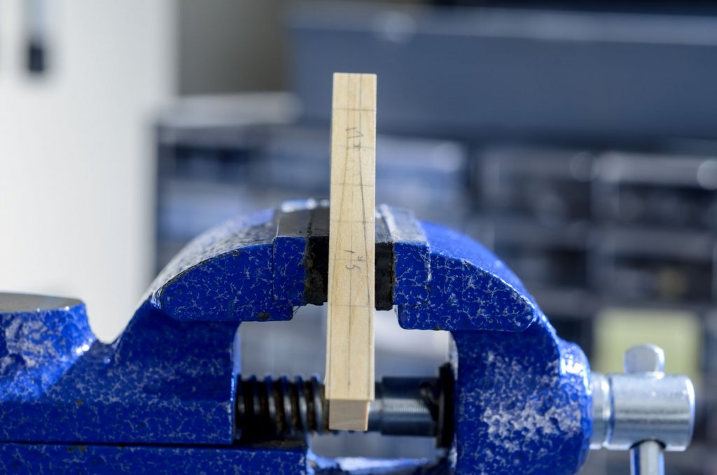
In an earlier post I noted stains coming from the black rubber protectors I purchased for my small hobby vise. I tried removing them with alcohol, acetone and lacquer thinner with no luck at all. However, this product works great and does an excellent job on pencil marks too. https://www.amazon.com/BADGER-16-606-Model-Airbrush-Cleaner/dp/B003976GKE Mike
-
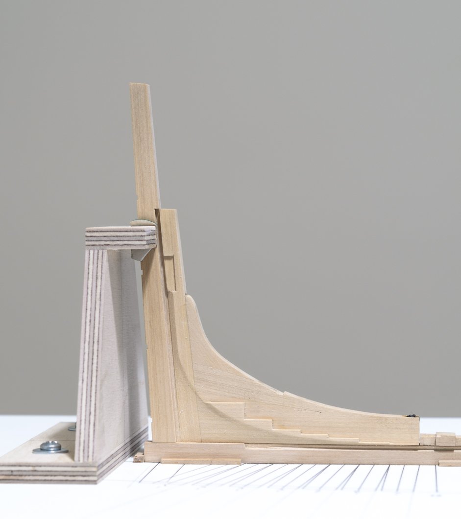
Its been a while since my last post. This might be considered a small update, but it feels more like a milestone. Before gluing the aft deadwood to the keel, I needed to add the inner post and sternpost to it and glue it down in one piece. The 12" sternpost has a straight taper down from the top to 10" at the keel. I shimmed the bottom end up and milled a rabbet on both sides. Gudgeon strap scores were milled prior to tapering. The 15" inner post has no taper. There is a score on each side for the "feet" of the fashion pieces. Due to the two fashion pieces having different dimensions, both scores are the same depth and width though not the same length. The aft side of the inner post, below the scores, needed to be reduced to a width equal to the space between the rabbets in the sternpost. Once that was done, more shaping of the bearding line was done to make the transition from the deadwood to the aft end of the inner post gradual. After gluing the completed stern components to the keel, I added the aft support. Mike

-
Kurt, That's very kind of you. Not only the rejects but the frustration in having to do things over. If I learn something from it and am happy with the result then it is all worthwhile. Mike
-
Cliff, So far it's all boxwood and for the upcoming frames as well. It would be hard to tell the finished appearance from my photos. I will be applying W-O-P to protect the wood later on and that will change things a bit too. If you want me to send you a sample both ways, then pm me. Mike
-
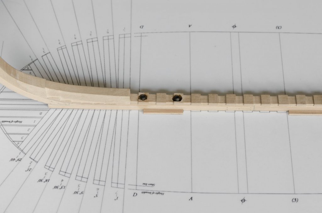
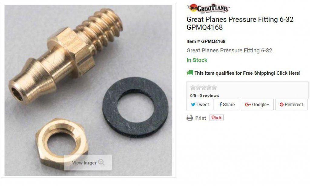
The central spine is held down to the building board using four 6-32 bolts. These bolts will also be used for the pedestal stands later. Mortises must be made to recess the nuts below the rising wood surface. I made the mortises using the Dremel and a 1/32" engraving bit. I did the first mortise using a standard hex nut that I ground down. After that, I decided to look for a smaller nut from the many parts bins I had stored away. Luckily, I found some pressure fitting nuts. (When I was flying controline aerobatics these pressure fittings were often used to change the characteristic of the motor run, via pressure from the motor exhaust to the fuel tank). The brass nut you see here is much narrower and thinner than a standard one and no grinding is necessary. I used these on the three remaining holes. The nuts were adhered to the rising wood with epoxy after securing the keel to the board. A drop of oil was applied to the end of each bolt thread and the excess wiped off to prevent any possibility of accidental adhesion between the bolt and nut. The aft deadwood is bolted, but not permanently affixed to the keel' Mike

-
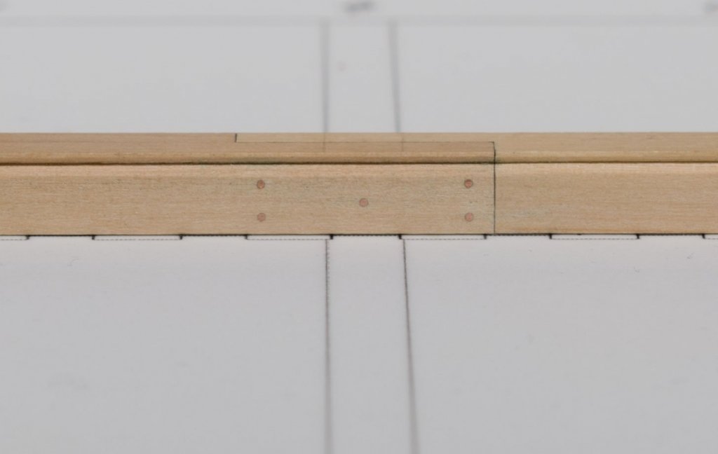
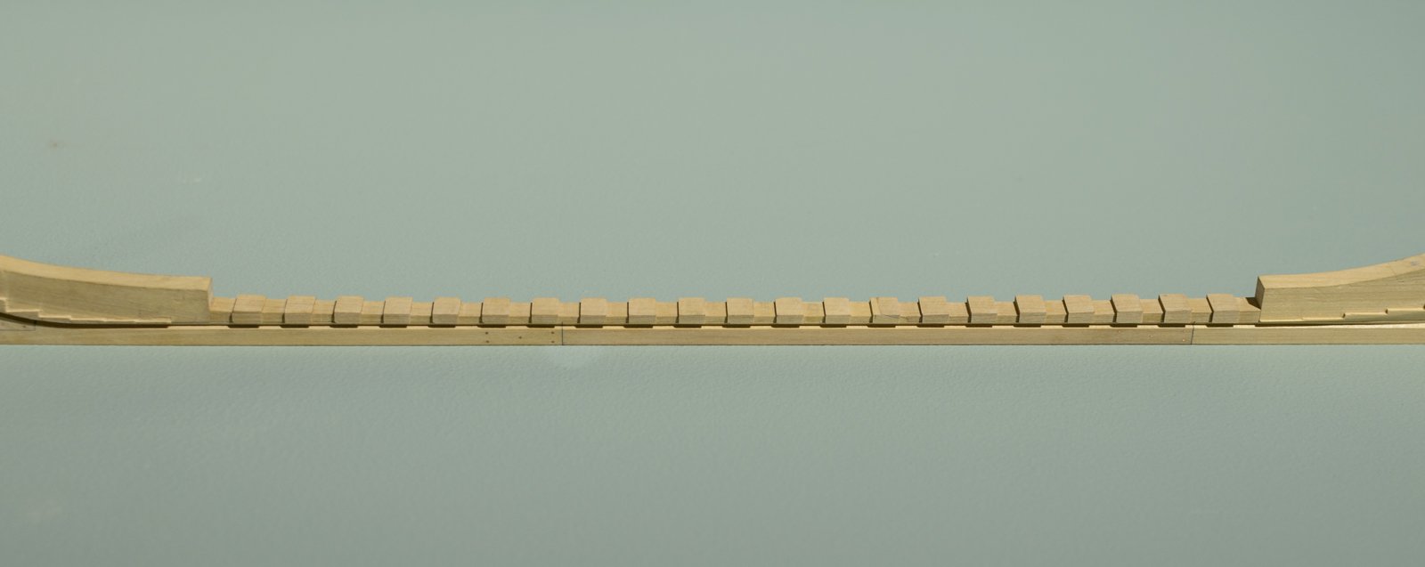
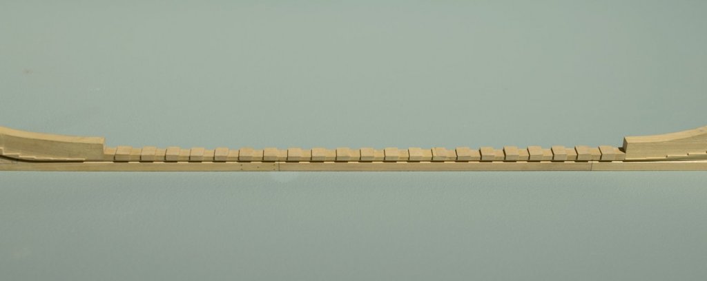
Thank you druxey, Ed, aviaamator, bdgiantman2 and Thomas for the nice comments and for all the "Likes" I managed to complete the rising wood over the past few days. It was made in two sections joined by a scarph joint. Most of the work was done on the mill with some minor adjustments done with needle files and miniature chisels. (http://www.leevalley.com/en/wood/page.aspx?p=72391&cat=1,41504). I made sure that station line locations on the building board lined up with those same locations on the rising wood. When everything lined up perfectly, the space between station lines was then divided up evenly and transferred to the rising wood. Mike
-
Thank you, Kurt! I'm still thinking about it and should have something worked out soon. Mike
- 452 replies
-
- 3
-
-
- cheerful
- Syren Ship Model Company
- (and 1 more)
-
Will do, druxey. Thanks for the reminder. Mike
-
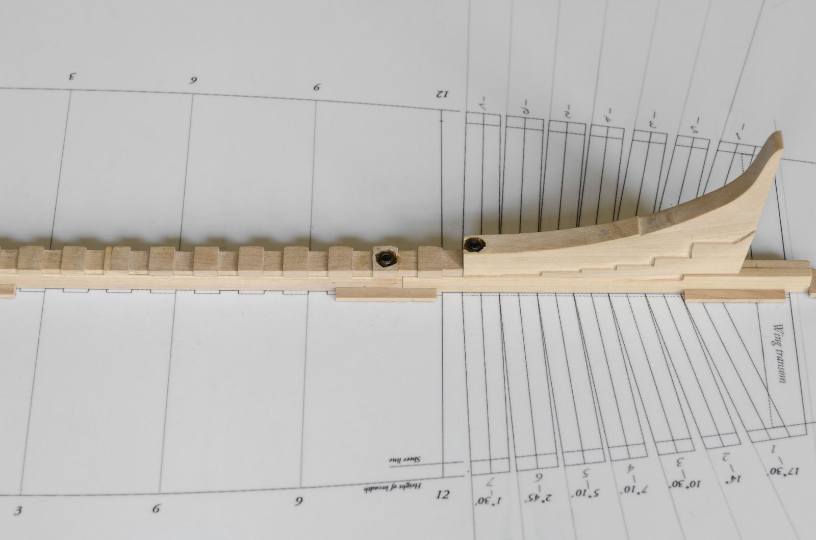
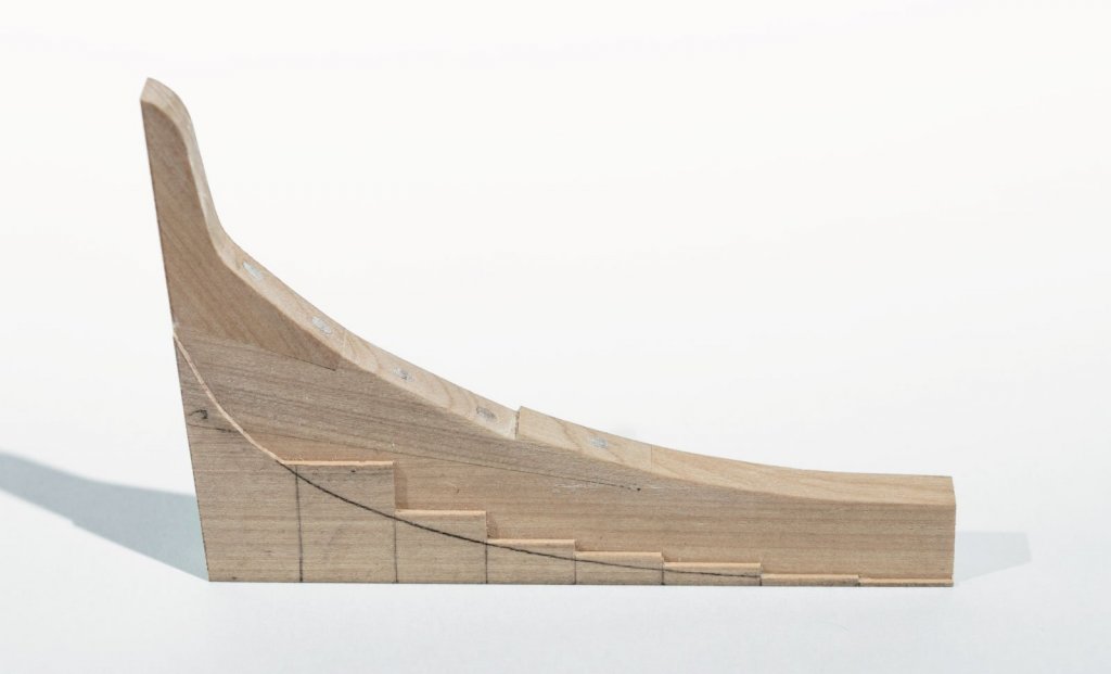
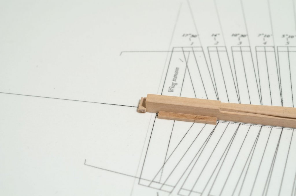
Work continues with the completion of the aft deadwood. 15" stock was joined in three sections, doweled and milled to 12". This is necessary in order to produce the stepping line for the aft cants. The forward most stepping line is only 1" high or .020 actual. I'm no mill man, but having one for this kind of work really helps. The bottom shape is approximated here as a starting point for determining the shape of the taper. I tapered it from the bearding line down. I later found that the rubber protectors that protect the wood while in the vise were creating a stain on the sides of the deadwood, especially the fore deadwood. Luckily this won't be visible later. f Like the fore deadwood, adjustments were made to the stepping line for cant frame alignment. Mike
-
That's right, Greg. I finished off the steps with a chisel while double checking that each step was in the correct position. After locking in the keel position with a small strip I found that a few steps were slightly off by a 1/2" more or less. I figured better to correct it now when I could do it off the building board. Mike
-
Cliff, Thanks for your interest in my build. I run the #2b pencil over the joint edge several times until fully darkened. For a darker joint, you could go with a #4b pencil. Mike
-
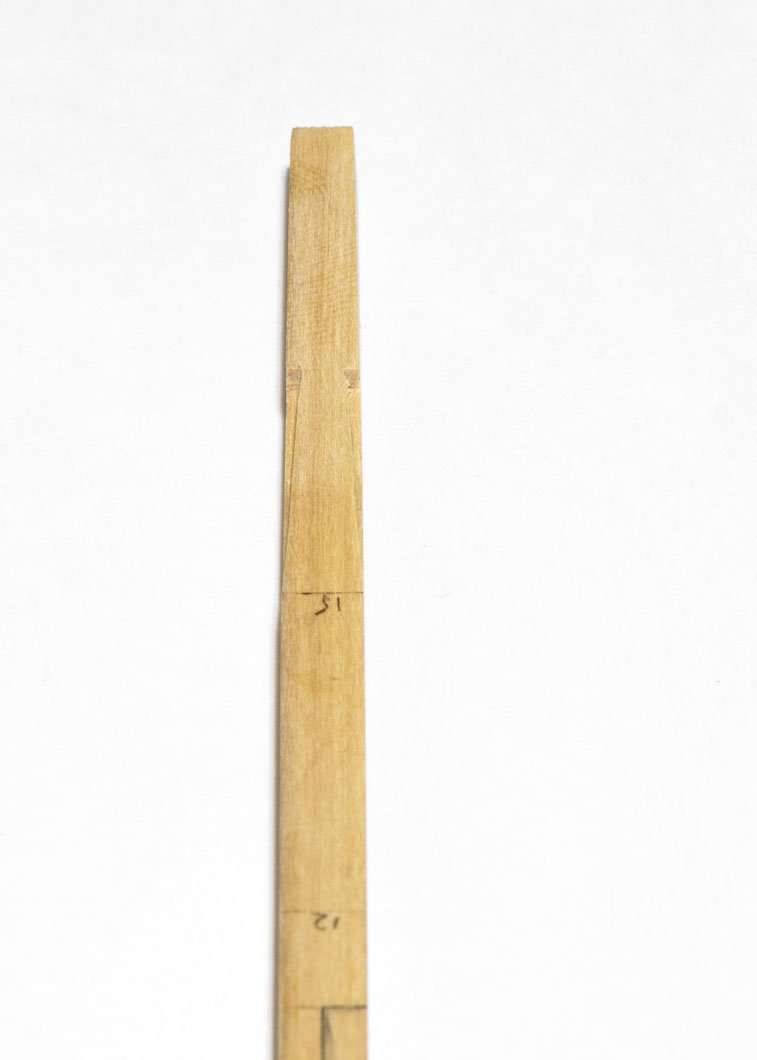
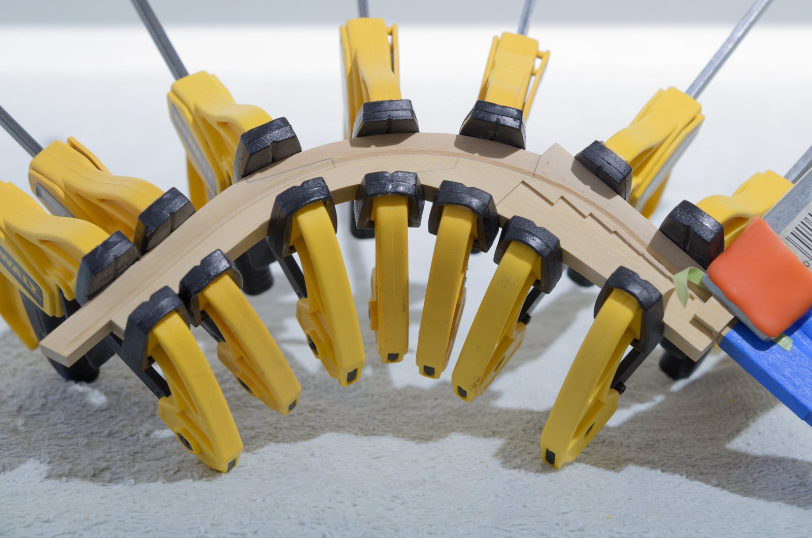
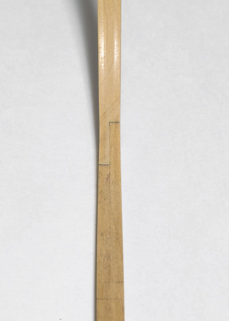
Making progress, albeit rather slowly. As they say, “The hurrier I go, the behinder I get.” The tapering of the keel and stem should be done before the rabbet is cut. The fore end of the keel is tapered from 12" to 10". This also reduces the width of the lower stem at the boxing joint. From there the stem is given a gentle taper to full width just below the whales. The transition from the boxing joint to the stem can be tricky, so care was taken while sanding. The aft end of the keel is also tapered down from 12" to 10". Once all the tapering is completed, the rabbet can be cut. The rabbet has been turned vertical and is approx 2 1/2" deep. This will allow for some adjustment later when the 3" planking is added. The fore deadwood and stemson where made from 15" boxwood sheet. The stepping line was done on the mill. There was no visible light coming through the joint prior to gluing. Those clamps come in handy! Mike


-
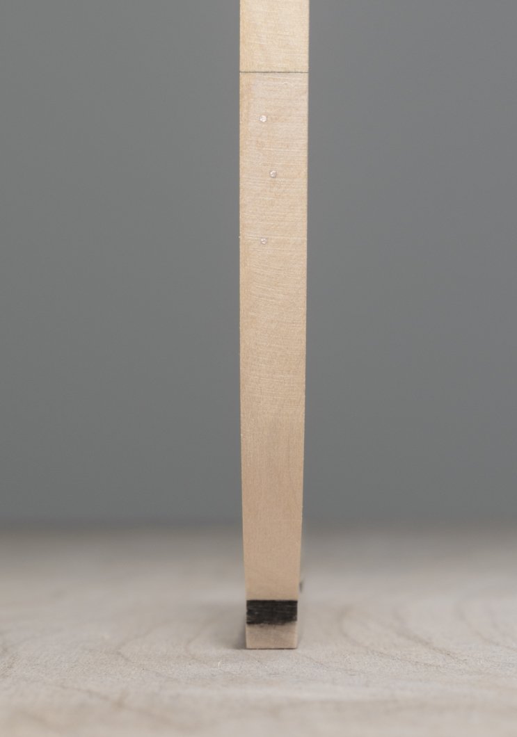
There are two ways that I know of to make the rabbet for the keel. One being a V-gouge and the other being a scraper. I have made some headway into learning how to use my chisels, but in the end I decided to play it safe and go with the scraper. The scraper was made from a hacksaw blade. After annealing, the shape was developed using a Dremel cut off wheel and some needle files. Although these enlarged photos might suggest otherwise, the 2" deep rabbet has a knife edge at the top of the keel and onto the stem. I spent a long time doing the rabbet, with very gentle pulls for fear of slipping or gouging the wood. Mike