HOLIDAY DONATION DRIVE - SUPPORT MSW - DO YOUR PART TO KEEP THIS GREAT FORUM GOING!
×


Stuntflyer
-
Posts
1,197 -
Joined
-
Last visited
Content Type
Profiles
Forums
Gallery
Events
Everything posted by Stuntflyer
-
 Thank you all for your interest in my new build and for all the "Likes". The three section keel is completed with the exception of the rabbet and joint bolts. The stem has been nailed for strength using 24 gauge copper wire. The tarred joints are done with a #2 pencil. The stem is in position relative to the baseboard and the support is secured as well. The keel is aligned straight and given side support from boxwood strips. I am starting to appreciate just how useful chisels can be when making these joints. I used to finesse them with a #11 blade and needle files. No wonder it took me so long. Mike
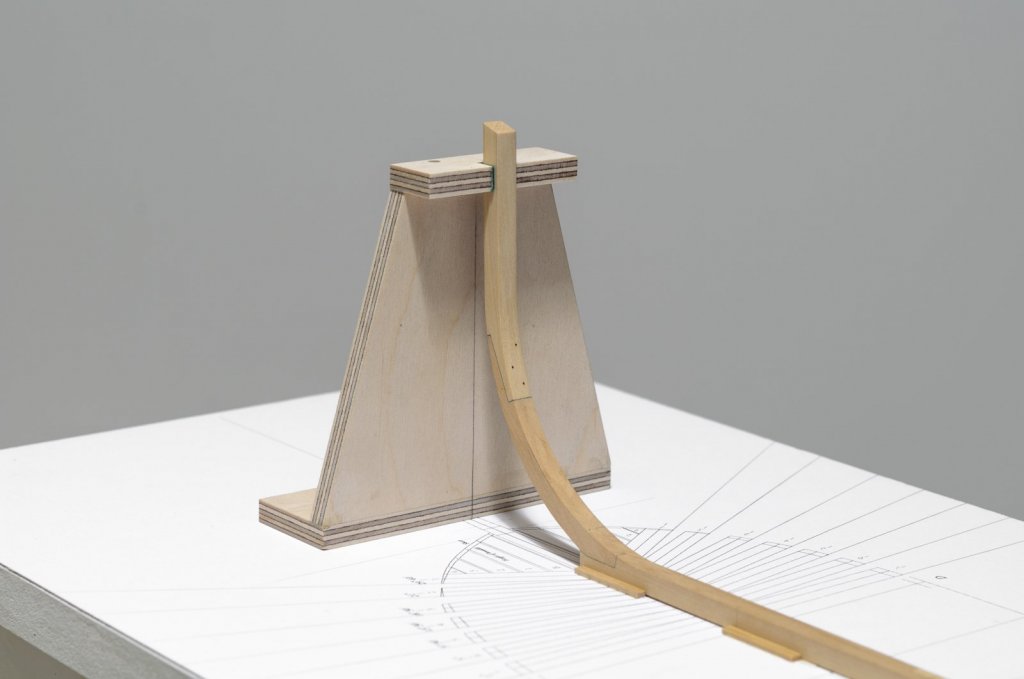
-
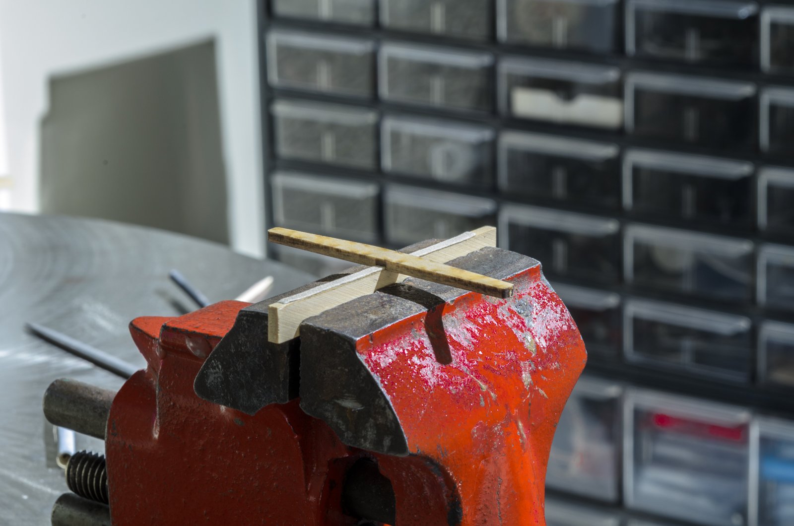
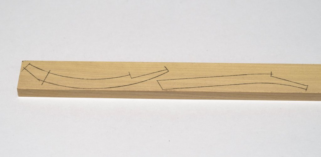
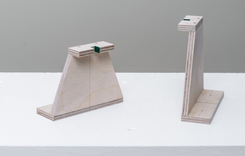
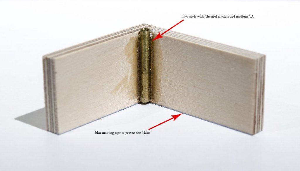
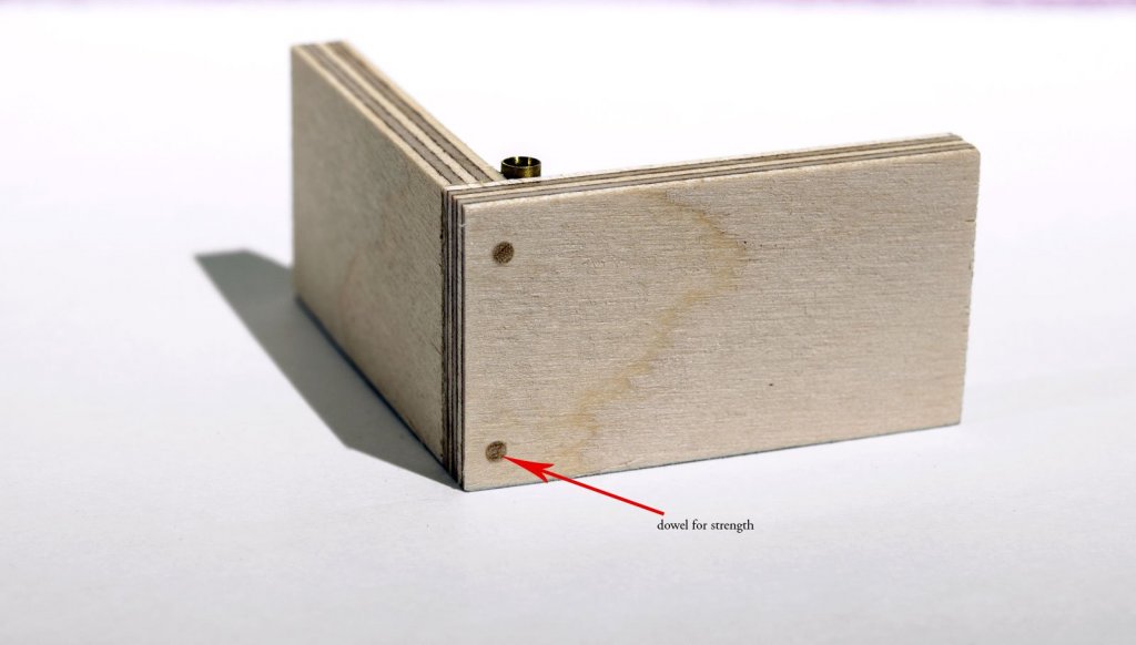
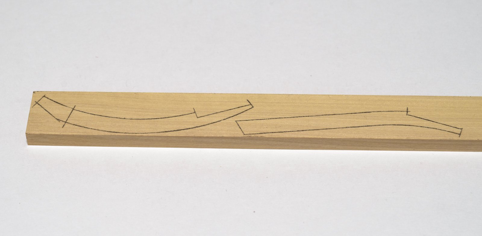
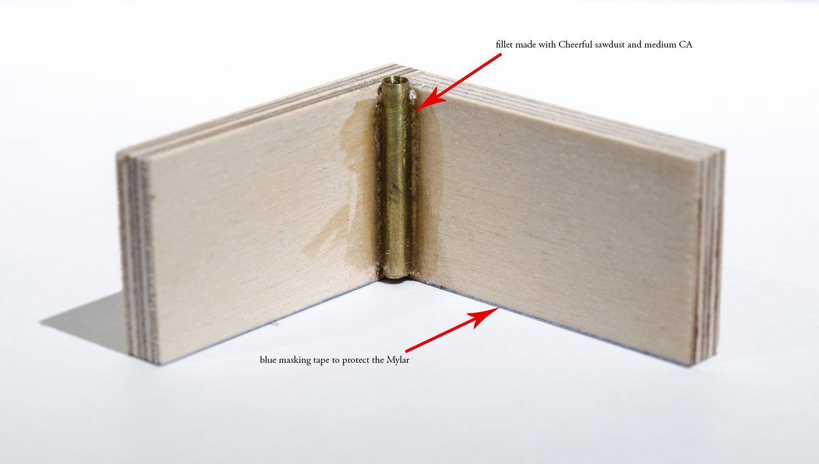
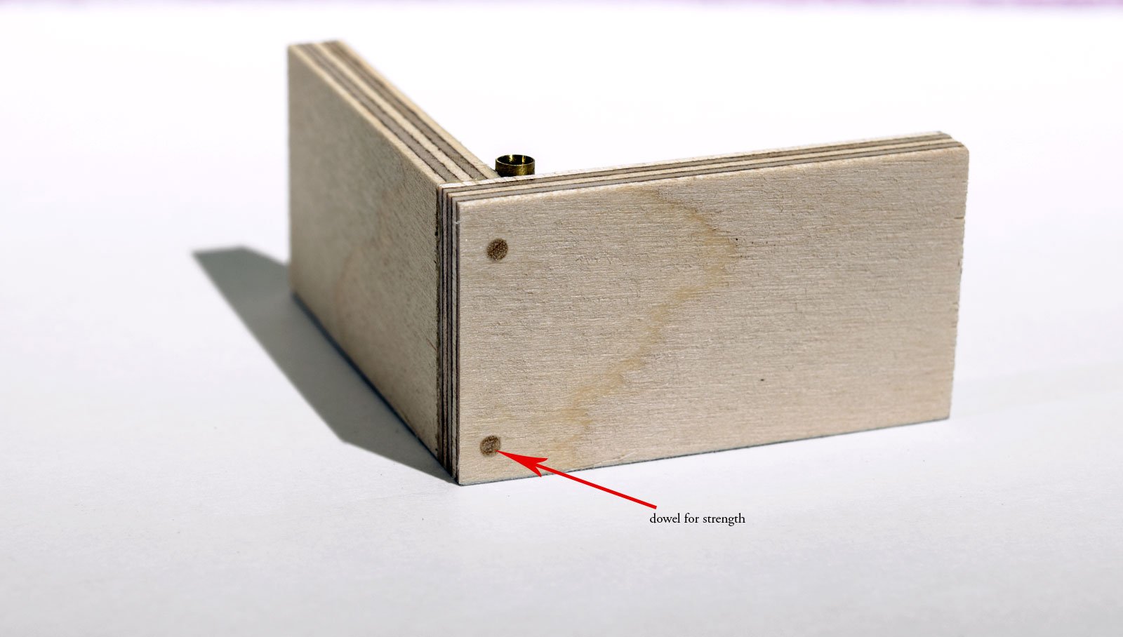
Hello everyone! After completing the building board I made the end supports for the central spine. They were made from 1/4" plywood and doweled for strength. Both supports have a 1/4" (actual) wide slot. I figured in the width of sticky back felt when cutting the slots. I'm using graphite transfer paper to trace drawings like the lower and upper stem. I should have some photos of the joined keel parts soon. Mike
-
Looking super nice, Thomas! Full size views show really nice detailing Mike
-
I'm no expert, Chuck. Looks very nice to me. Mike
- 269 replies
-
- 5
-

-
- Queen Anne Barge
- Syren Ship Model Company
- (and 1 more)
-
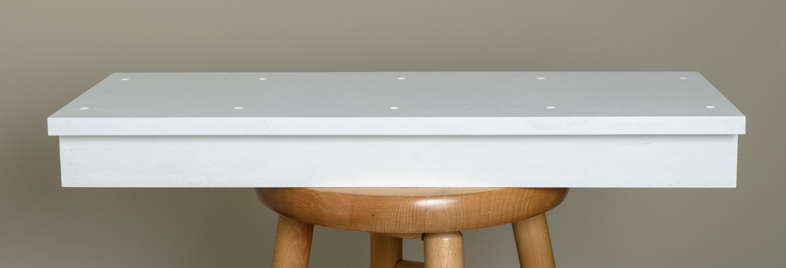
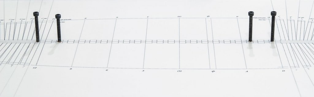
In an earlier post, I mentioned that the paper drawing for the building board was moving a bit due to high humidity. Even though my newly acquired dehumidifier flattened the drawing, I was skeptical about it remaining dimensionally stable. With that in mind, I removed the drawing from the board and replaced it with a Mylar drawing. Other than drawing directly onto the board itself, Mylar would be a good option to use. Holes for the pedestal mount need to be drilled. Since the building board is too wide to get a center hole on my drill press, I had to make a jig to allow for a 90° hole. The jig is made from scrap plywood 2 1/2" x 1/4" x 1 1/2". The brass tube is 1/8" i.d. The holes were drilled with a 1/8" x 6" long drill bit. I chose to use the Dremel tool instead of a hand drill as it allows for more control and places less side pressure on the jig when drilling. After center punching the hole locations in the building board, I drilled down approx 1/8" to establish the hole. The drill was then placed through the brass tube and into the shallow hole. Then it was simply a matter of holding the jig down firmly while drilling deeper. Note: To avoid any wobbling when using a long a drill bit, remember to shut off the Dremel before removing the drill bit from the hole. Afterwards I opened the holes for the 6/32" bolts that will used to hold the pedestals. After removing the bolts, the outer edges of the holes were cleaned up. Mike
-
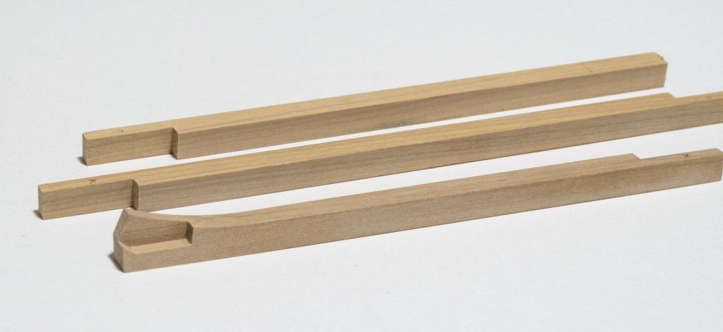
The 12" keel is made in three sections. The fore end has a boxing joint. I chose to make the fore section using two pieces of 6" wide stock in order to simplify the joint making process. Chisels were used to clean up the joint after cutting the initial shape with a scroll saw. The vertical scarph joints were made on the table saw. Mike
-
Michael, I had a lot of fun building her and Chuck's laser kits for the ship are great. Mike
- 452 replies
-
- 6
-
-
- cheerful
- Syren Ship Model Company
- (and 1 more)
-
Thank you all for the kind words and "Likes". Ryland, it was great seeing you at the Naval Academy while we checked out the Rogers Collection. If you are ever in the area, we usually have our club meetings the last Tuesday of the month. Erik, I will get those additional photos posted next week sometime. Mike, I'm still trying to figure out the display case and stand. As soon as I have something, I will post it. Mike
- 452 replies
-
- 5
-
-
- cheerful
- Syren Ship Model Company
- (and 1 more)
-
Hello everyone, My new build log can now be found here. https://modelshipworld.com/index.php?/topic/16300-the-hayling-hoy-1760-by-stuntflyer-mike-148-scale/ Mike
- 452 replies
-
- 6
-
-
- cheerful
- Syren Ship Model Company
- (and 1 more)
-
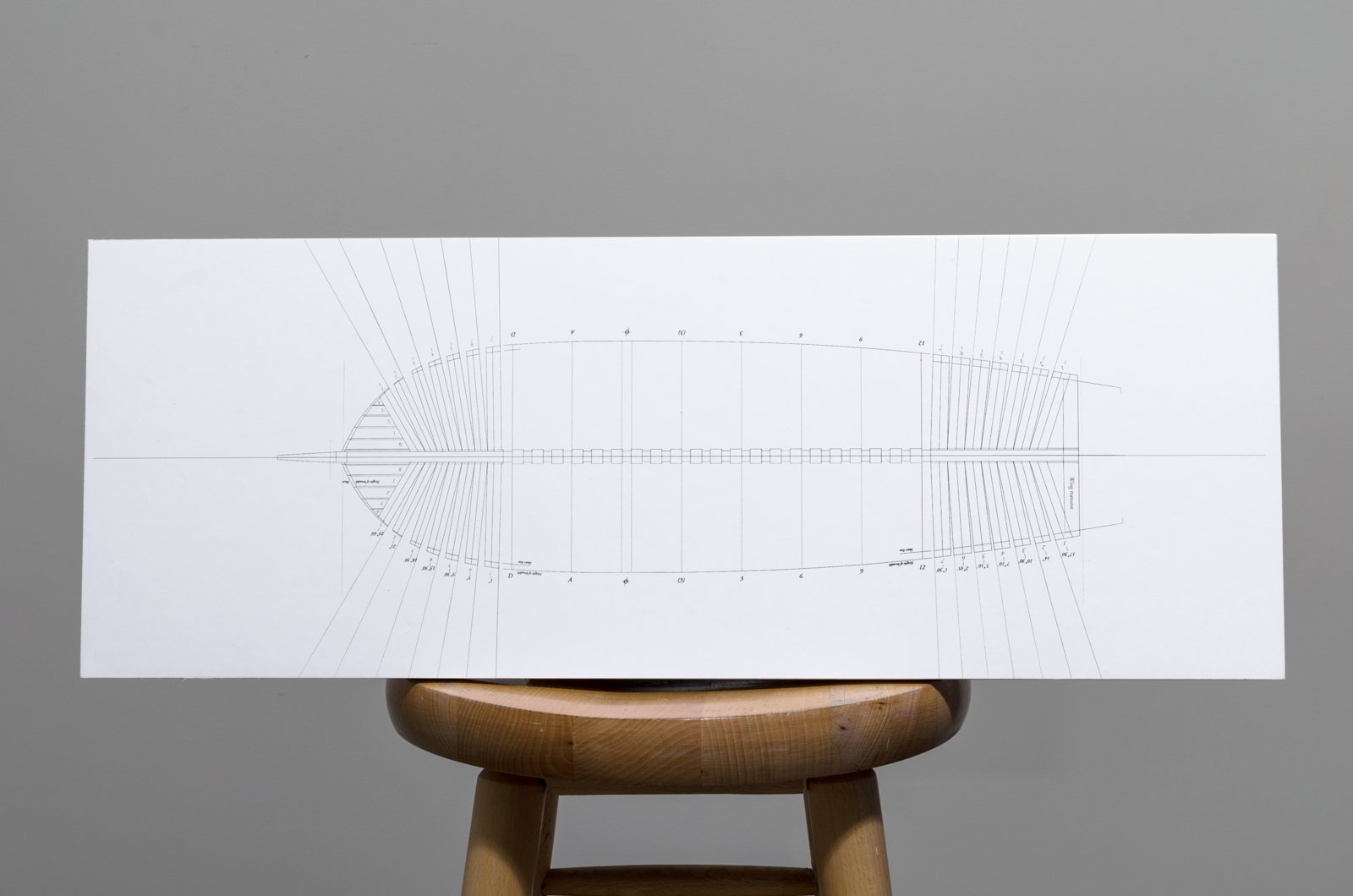
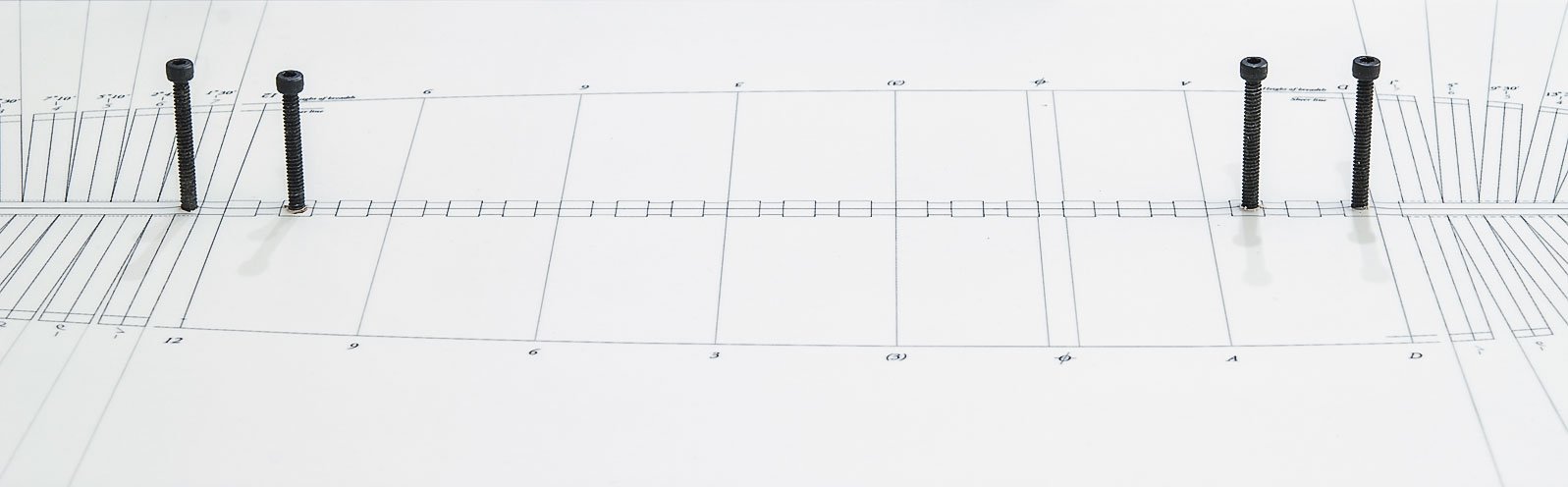
Welcome to my build log of The Hayling Hoy. This will be my first attempt at building a POF model. I am building Hayling from the plans drafted by David Antscherl, based on plans and documents in the Royal Museums Greenwich collection. I would imagine that without the RMG , that this build would never happen. So, a special thanks to the museum for making this build possible. Being a first attempt, I expect that there will be many do-overs along the way. In anticipation of that, I ordered 50% more boxwood sheets than the build would normally call for. All of the wood was supplied by Jason at Crown Timberyard. To play it safe, I went with 2" instead of 3" widths which should help to maintain flatness in the wood. To lessen the need for thickness sanding, Jason was able to supply sheets a few thousands over the scale inches needed. Much of the information for the build will be referenced from "The Fully Framed Model" Vol I thru IV at SeaWatch Books. https://www.seawatchbooks.com/SWBTitles.htm Before getting started, here are a few words from David Antscherl. . The Hayling hoy © David Antscherl 2017 What is a hoy? hoy, (bateau de passage, Fr.) a small vessel, usually rigged as a sloop, and employed in carrying passengers and goods from one place to another, particularly on the sea-coast, where ordinary lighters cannot be managed with safety or convenience. It would be difficult to describe, precisely, the marks of distinction between this vessel and some others of the same size, which are also rigged in the same manner; because what is called a hoy in one place, would assume the name of sloop or smack in another; and even people who navigate these vessels have, upon examination, very vague ideas of the marks by which they are distinguished from the above-mentioned. In Holland, the hoy has two masts; in England it has but one, where the main-sail is sometimes extended by a boom, and sometimes without it. This prolix, sub-clause filled entry in William Burney’s 1815 edition of Falconer’s New Universal Dictionary of the Marine leaves much to be desired in way of precise definition. Looking at plans of lighters and hoys, they seem to have much in common. Falconer defines a lighter as follows: lighter, (barque, ou gabare, Fr.) a large open flat-bottomed vessel, generally managed with oars, and employed to carry goods to or from a ship when she is to be laden with, or delivered of, her stores, &c. However there were also sailing lighters, very similar to hoys. These were about 60 to 70 feet in length. Both had fairly similar hull forms and were also usually sloop or cutter rigged. Lighters were distinguished from hoys by the heavy davit (or sometimes two) carried forward over the bow. The other difference seems to be that only hoys carried passengers as well as goods. Where does the name hayling come from? Hayling Island, shaped like an irregular inverted ‘T’, is located close to Portsmouth, Hampshire. Portsmouth lies to the west across LangstoneHarbour and to the east side is ChichesterHarbour. The island is connected to the mainland by a bridge at its narrower north end. An iron-age shrine built on the island later became the site of a Roman temple. Salt production on the island, recorded in the Domesday Book, continued until the late 19th century. A chapel was established on HaylingIsland sometime in the 12th century. This became St Peter's Church, now the oldest surviving church there. Its peal of three bells, cast in about 1350, is considered one of the oldest extant in England. In 1944 the island was used for a mock invasion exercise as part of preparation for D-Day. Oyster farming was carried out for many centuries, and the oyster beds are now being restored. That the hoy would be named after the island is appropriate, as she was designed to work in the adjacent Portsmouth harbour. Why a model of a hoy? The choice of Hayling as a subject was chosen for several reasons. First, it is a subject rarely seen in model form. Secondly the hull, if fully framed, is considerably less complex to construct than even that of a sixth rate, but still illustrates all its principal features. There are no ports or sweep ports to frame. Also, there are very few chocked joints required in constructing the frames. The frames consist of fewer pieces than in larger vessels. Neither does a model of this size consume many board feet of expensive exotic wood. All these features make her an ideal subject for a first effort at ‘real’ framing. In addition, Hayling’s rig is comparatively simple. A rigged model, even at 1:48 scale, will not take up too much space. Lastly, there is no carved work. Carving is something that puts off many model-makers from tackling 18th century subjects. The only ornament, a simple scroll head, is a relatively easy feature to model. A brief history of the Hayling hoy. Hayling was constructed by the well-known builder Henry Adams of Buckler’s Hard. Nelson’s favorite, Agamemnon of 1781, 64 guns, was one famous product of his shipyard. Others included Indefatigable, also of 1781 and 64 guns, and the frigate Euryalus of 1803, 36 guns. Buckler’s Hard is situated 10 miles upriver at a bend on the west side of the BeaulieuRiver. The lower tidal part of the winding river enters the Solent opposite the Isle of Wight near Portsmouth. Hayling was the third vessel of that name. The first Hayling, of 117 tons, was purchased in 1705 and rebuilt at Portsmouth Dockyard in 1729. The second, actually the rebuilt, Hayling, also spelled Heylin, was converted into a sloop in 1759 for use as a floating battery off the coast of Africa. This triggered the order to construct her replacement, the third Hayling. “New Hoy propos’d in ye (the) Room of ye (the) Hayling” was written on a draught (zaz 5828) signed Allin and dated 30th August 1759. Joseph Allin was joint Surveyor for the Navy with Sir Jacob Ackworth. A copy of another draught (zaz 5829) was sent to Henry Adams on 27th September as “per contract”. Hayling was launched the following year in 1760. After 22 years of service, she was lost when she foundered in the Channel in 1782. (David Lyon, The Sailing Navy List 1688-1860, page 321.) This was a lengthy working life for a knock-about service vessel. Hayling’s armament, if any, is not recorded. Two of four of her draughts that are extant -dated August and September 1759 - show four swivel mounts on each side. However, her ‘as launched’ draught, zaz 5830, does not. Whether swivels were actually fitted or not is unknown, but probably unlikely. Sources of information The primary source of information is through the draughts held by Royal Museums Greenwich, formerly The National Maritime Museum. There are four draughts extant. The first is a design draught showing a scroll head dated 3rd August, 1759 (zaz 5827). It shows very little detail and some pencil alterations have been sketched along the topsides. The second draught (zaz 5828) is dated 30th August 1759. It shows a fiddle head and for swivel mounts a side. Far more detailed than the first draught, it includes the profile and weather deck details in red ink. Titled “New Hoy propos’d in y(e) Room of y(e) Hayling” this draught has the signature of approval of Joseph Allin, joint Surveyor of the Navy. A third draught (zaz 5829) is also much more detailed, and is annotated as follows: “A Copy for this was given to Mr. Henry Adams for Building the Vessell (pr Cont’t) 27th Sept. 1759”. This also shows four swivel mounts a side and a fiddle head. There must have been more than one copy, as this draught is titled “A Copy of A Draught for Building A New Hoy in the Room of the Hayling for the Use of his Majesty’s Yard at Portsmouth”. The fourth detailed ‘as launched’ draught (zaz 5830) gives a table of dimensions of all Hayling’s masts and spars. It is undated, other than a modern pencil annotation of 1760, but states that her ‘Draught of Water when Launch’d Fore 5(') 5( ") Abaft 7(') 0("). No swivel mounts are shown. This must be the yard draught that was subsequently filed with the Admiralty. Further inboard details were gleaned from the draught of a 56' 0" mooring lighter (zaz 5895) dated 1764. This, conveniently, shows a cross-section from which I lifted scantlings for the longitudinal members of the vessel. To start things off I needed to construct a building board. This was made from 3/4" x 10" x 27" M.D.F. It is supported by 1" x 3" pre-primed pine battens longitudinally beneath. 1 1/2" dry wall screws were counter sunk into the M.D.F. to hold the battens in place. After checking to see that the board was flat in both directions it was given two coats of primer using a roller. The board drawing was then adhered to the building board with 3M Super 77 Spray Adhesive. Now, we have had a few humid days here and I noticed a slight wrinkling in the paper afterwards. This reminded me of some of the issues that Ben was having with his HMS Pegasus. In an effort to keep the humidity under control before this got even worse, I purchased a small room de-humidifier. In only a few hours the wrinkles disappeared. I keep the RH levels at 50% more or less. Note: I extended the fore and aft cant lines to make it easier to setup those frames later on. Mike
ZAZ5830.thumb.jpg.87a139c8286f9f20013a360f2a254bcb.jpg)


-
Thanks guys for the comments and "Likes". I should have the new build log up and running fairly soon. I will paste a link here when all is ready. It's gonna be fun! Mike
- 452 replies
-
- 4
-
-
- cheerful
- Syren Ship Model Company
- (and 1 more)
-
Thank you all for the kind words and "Likes". Mike
- 452 replies
-
- 2
-
-
- cheerful
- Syren Ship Model Company
- (and 1 more)
-
I completed the entryway stanchions and the flag over the weekend. This basically completes the model except for the stand and case. In the end I decided not to do the buoys. I did make them, but wasn't all too happy about how they looked. It's been a little over two years since the start and I have enjoyed the journey tremendously. I have learned so much and also made new friends along the way. A special thank you to Chuck for the tremendous support that he has given me since I started this project. The many things that I learned from him will surely be useful on future builds. Speaking of which, stay tuned. . Mike

- 452 replies
-
- 27
-
-
- cheerful
- Syren Ship Model Company
- (and 1 more)
-
Sorry to hear this, Bob. However I know that your repair work will look great. Mike
- 682 replies
-
- 4
-
-
- halifax
- lumberyard
- (and 1 more)
-
Thank you all for your comments and "Likes". I'm off to the United States Naval Academy today in what should be an eye opening experience. Other SMSNJ club members will be there as well. Very excited! Mike
- 452 replies
-
- 5
-
-
- cheerful
- Syren Ship Model Company
- (and 1 more)
-
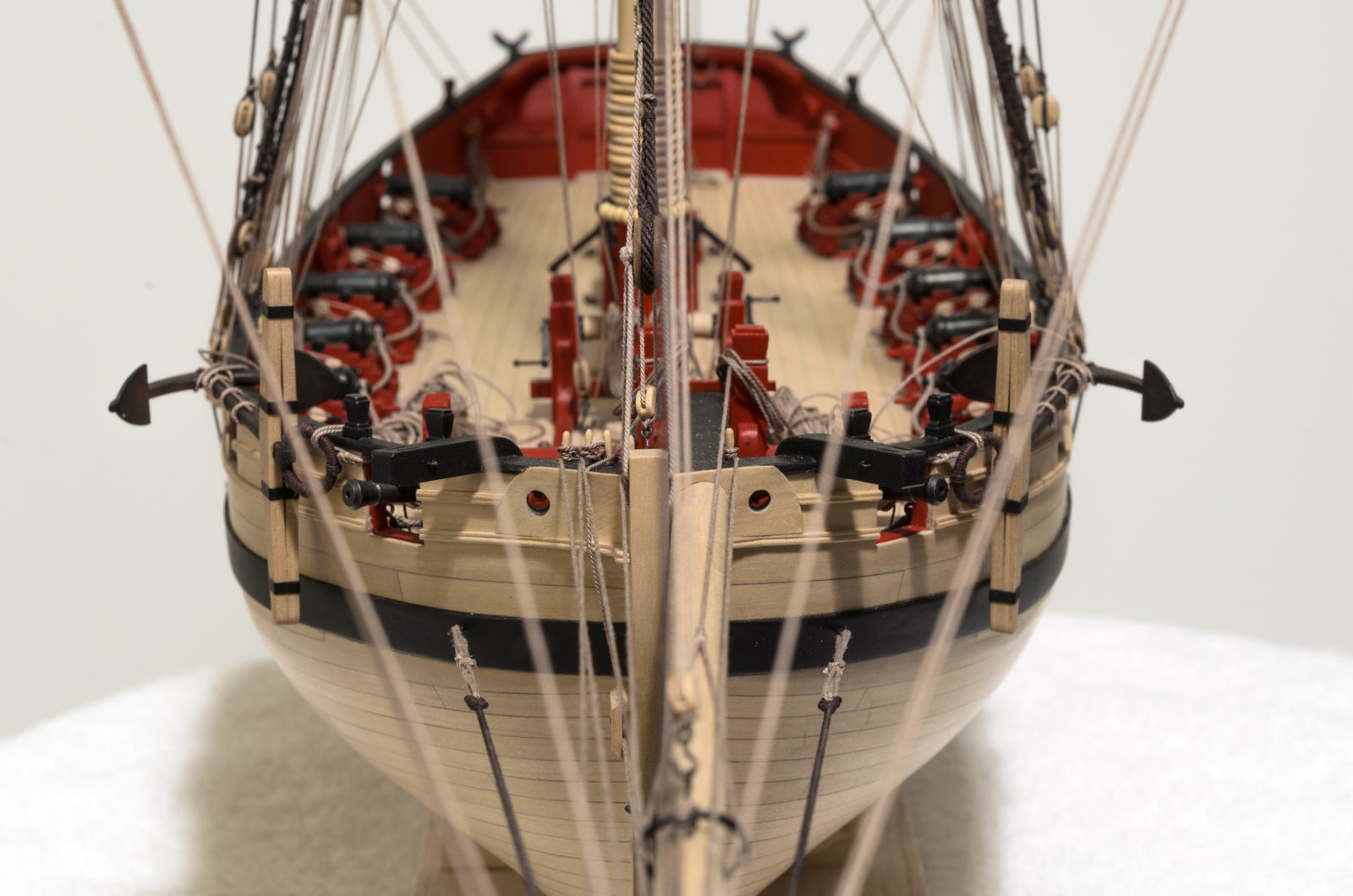
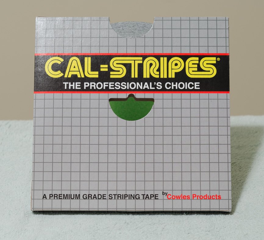
Work continues on the anchors and their rigging. I used Grimy Black and Rusty Red powders for weathering. The bands are made from striping tape cut to a width of approx .070. Puddening was done with .008 Dark Brown, close to 80 wraps each. Anchor and buoy rigging are .018 Light Brown. Speaking of buoys, that's next. Mike


- 452 replies
-
- 23
-
-
- cheerful
- Syren Ship Model Company
- (and 1 more)
-
Thank you so much for the comments and "Likes". Tom: The tri-state meeting in New London, CT is an event that I should attend. I will look into it and would most likely bring Cheerful along. Mike
- 452 replies
-
- 6
-
-
- cheerful
- Syren Ship Model Company
- (and 1 more)
-
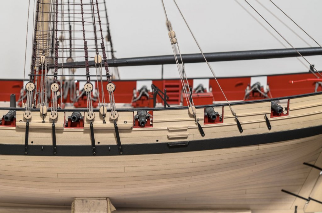
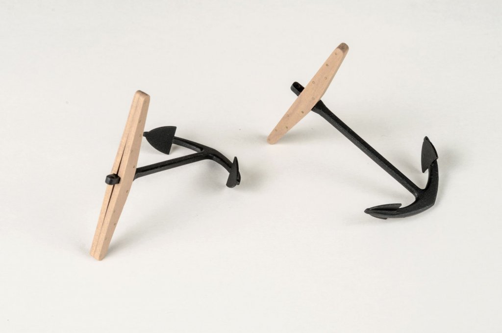
All of the remaining rope coils have been completed. I found this to be an exercise in patience and sticktoitiveness. Lines had to be re-tensioned and in some cases the number of belays were reduced to remove unnecessary bulk around the belaying pins. To avoid disturbing the surrounding rigging, I used tweezers, one in each hand, as fingers to re-tensioned and belay. A tiny drop of PVA was used under the pinrail to hold the rope while belaying. With six belaying pins on each side, the coils sometimes overlap slightly. Making seven instead of eight holes in the pinrail would allow for spacing the pins further apart. However, I'm not sure if Chuck would agree. Here are a few photos of the completed work. I'm really enjoying making the anchors from Chuck's kit. The slot in the stocks were first deepened leaving a thickness .045". If you don't do this, the air gap between the two stocks will be too wide. I used some sticky back sandpaper adhered to a 3/32" strip to achieve the required depth. I found that there was better control if I moved the stocks across the sandpaper rather than the other way around. I finally had a chance to test out a milling machine that I acquired recently from a fellow member. I had never used one before, so I was anxious to give it a go. It made simple work of making inline holes for the #76 treenails. I used Chuck's method (chapter 1 of the monograph) which uses a pencil to outline each hole along with a neutral toned filler. Next, the rings, bands and then those fiddly buoys. Weathering will be done later after all the parts are completed. Mike


- 452 replies
-
- 32
-
-
- cheerful
- Syren Ship Model Company
- (and 1 more)
-
Hello Johann, I'm just now doing a full read on this marvelous build log. The metal work is fantastic! Mike
-
Nice progress, Bob! It looks like planking that bluff bow might have been a bit challenging? Mike
- 682 replies
-
- 3
-
-
- halifax
- lumberyard
- (and 1 more)
-
Thank you all for the comments and "Likes" Sure, Rusty! I'll make you as many as you want if you will do my rope coils. Mike
- 452 replies
-
- 3
-
-
- cheerful
- Syren Ship Model Company
- (and 1 more)


ZAZ5830.jpg.941b22ab3878aa37371ed2566dd8f3cb.jpg)