Stuntflyer
-
Posts
1,126 -
Joined
-
Last visited
Content Type
Profiles
Forums
Gallery
Events
Everything posted by Stuntflyer
-
 I could be wrong, but I think that Frank is talking about the hawse holes.
 -
Yes, the angles are tricky. Start with a small diameter drill. A round needle file helps as well.
-
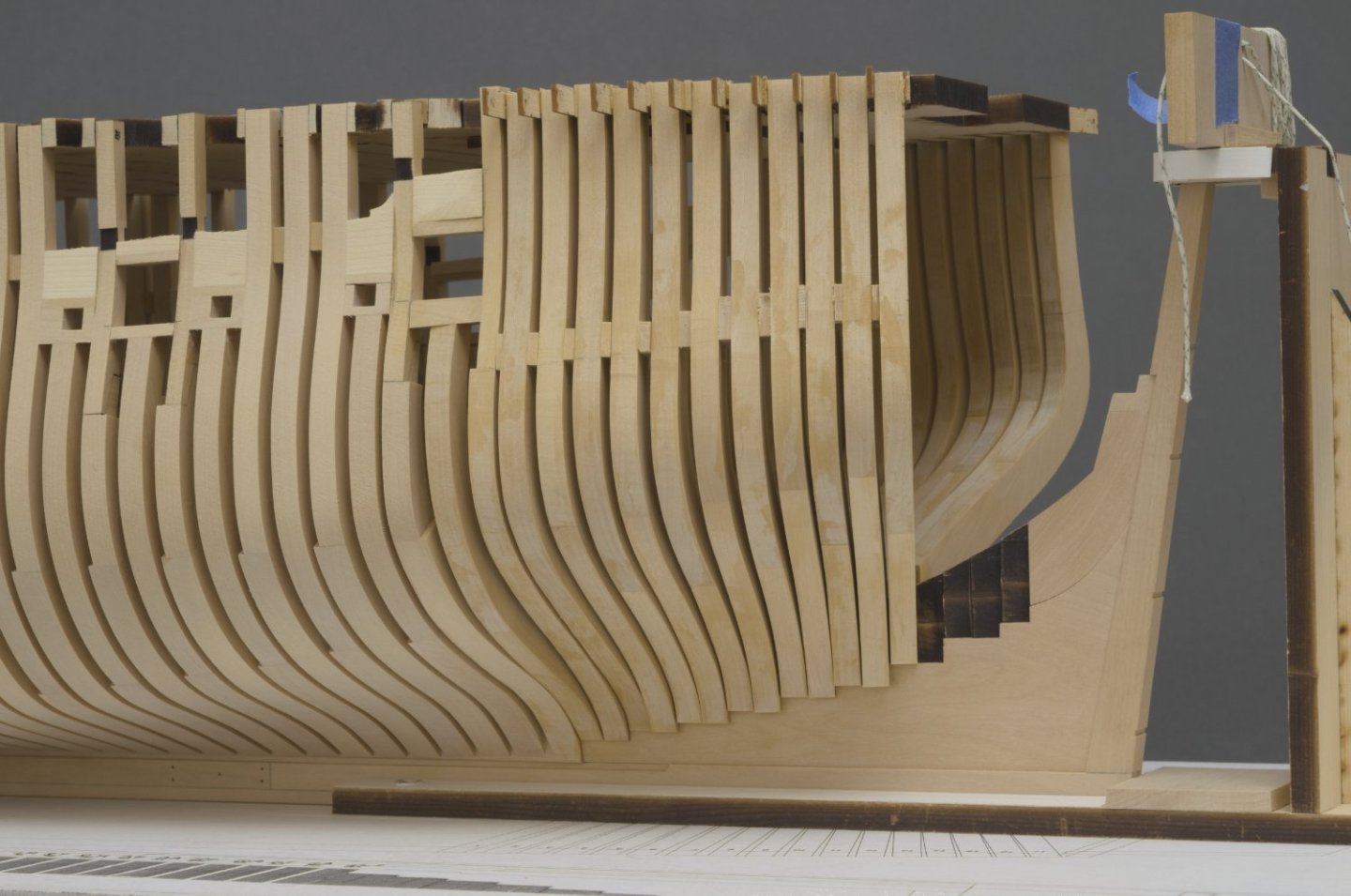
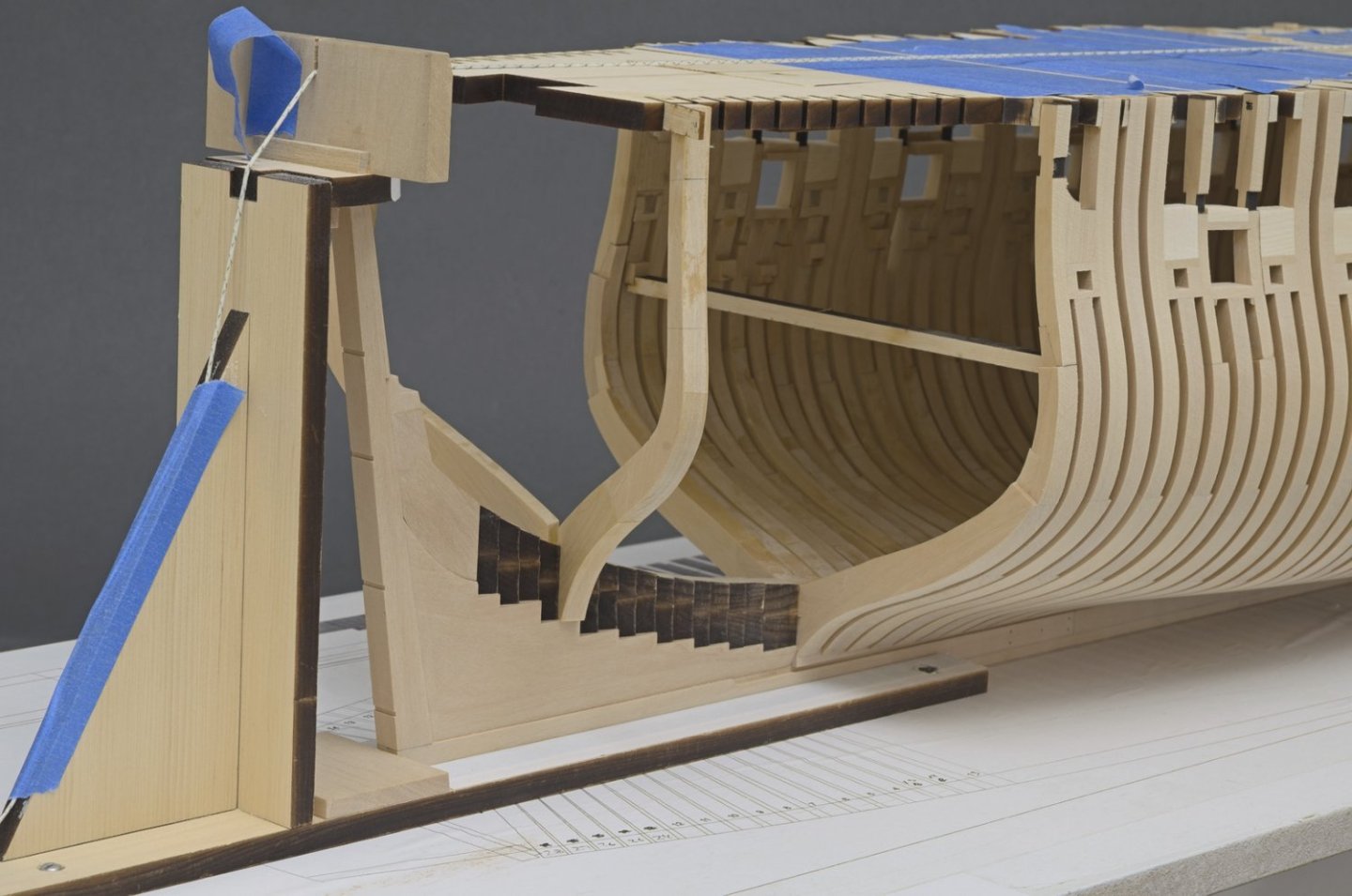
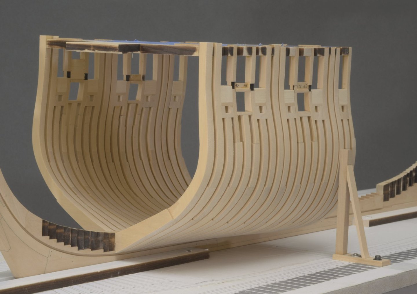
I've been moving right along on the aft cant frames. Just like the fore cants, there is a long span between the upper and lower attachments which results in some flexing. To stiffen things up I placed chocks between the frames. This will help greatly to keep the frames from breaking loose while fairing. The chocks were placed in the area between upper wale and the lower planking strake. They will be completely hidden. Mike
-
Brian, There will be quite a bit of interior details. I have not seen the plans for that, so I can't say exactly what details will be on the ship. Erik, I do try and get everything right when I install a frame. Using the machinist squares makes it rather easy to accomplish this. Something I like to do is to adjust the foot of frame to sit flush into the deadwood with no gaps showing. I'll use the disc sander for this, hand turned. None of this is difficult, just takes more time. With so many parts and small details to look at it's hard to say just how much of this will be noticed after the ship is finished. Mike
-
Cant frames (aft) Framing continues with the install of aft cant #24. This is basically a repeat of what was done with the fore cants. Just less work overall. Anyway, here you go. Mike
-
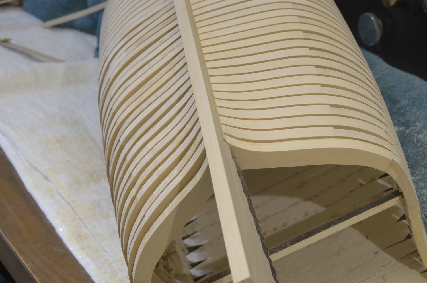
Greg, thanks! Not knowing exactly how it was going to fair, I had a real sense of relief when it turned out okay.
-
Thanks, Chuck!
-
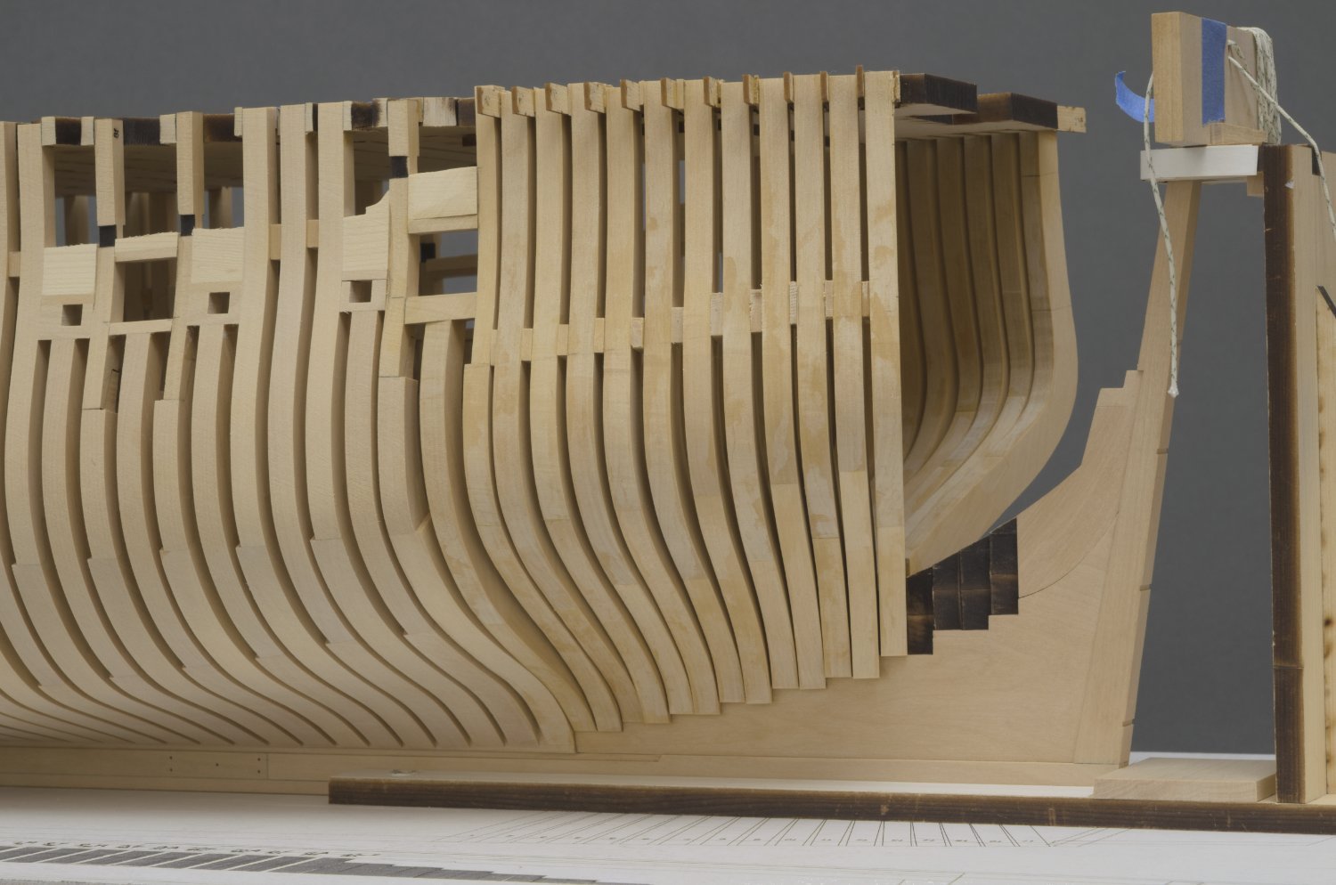
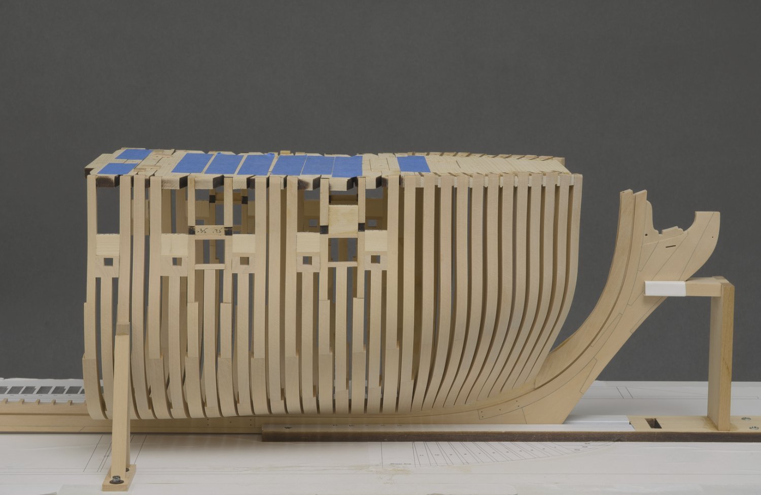
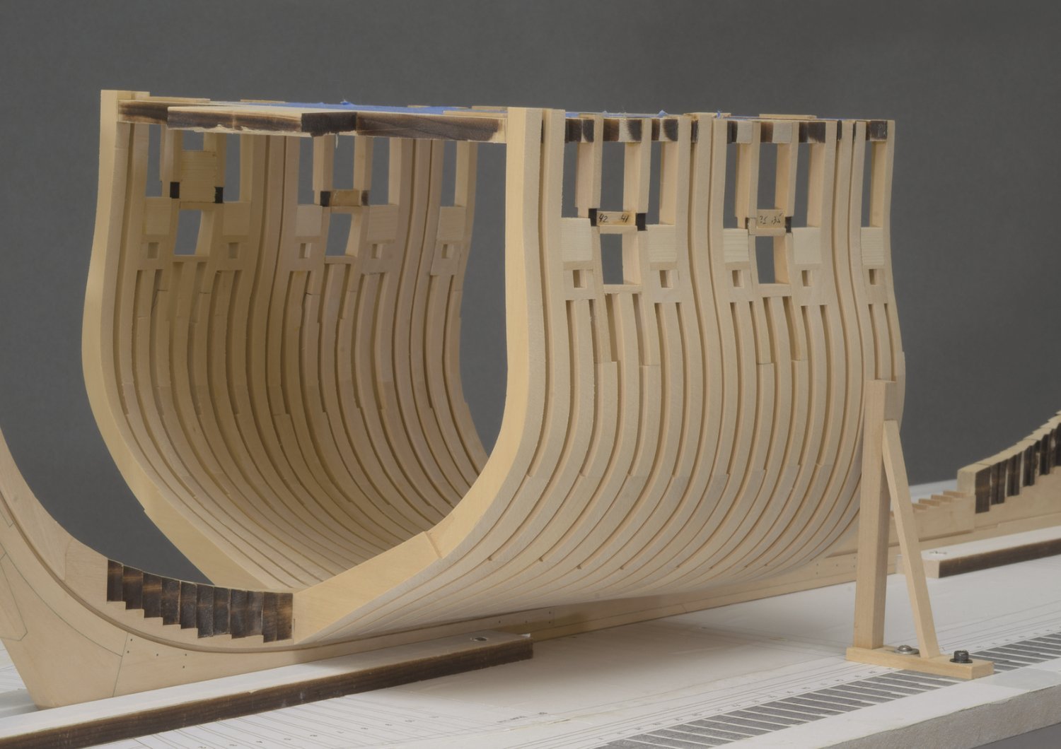
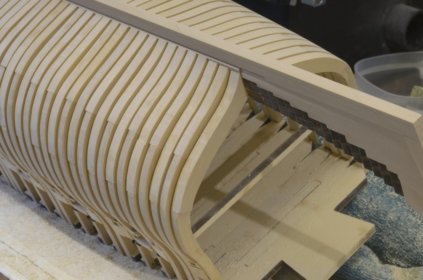
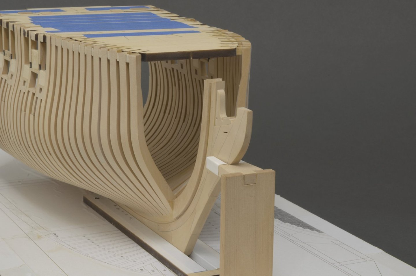
In spite of a mild case of vertigo, I managed to fair most of the port side frames. I purposely left the last 2 or 3 aft most frames partially faired. I recommend doing that in order to avoid any chance of over fairing when there are no additional frames to guide you. So, I will wait until I have some aft cant frames installed before I do any more fairing. I shot these photos to give you an idea of just how much wood needs to be removed. Judging from this, I am sure that the cants will require even more work. Mike

-
Whaat! Your not into selfies?😁
-
Welcome back Erik!
-
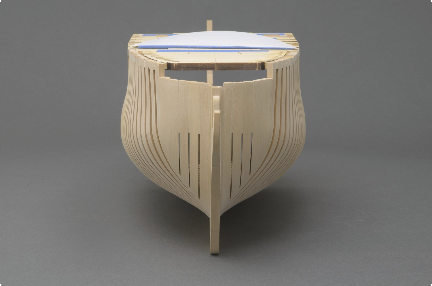
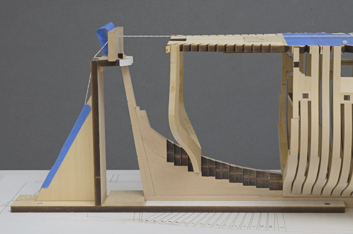
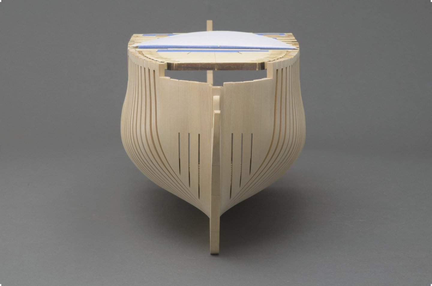
The last of the square frames were installed over the weekend. A little over six months for all the frames so far. Now the fun begins. Time to grease the elbows and start fairing. I'll be working mostly aft from the vertical support jig which is attached to the build board. Also I made tick marks on of a few of the cant frames that are in need of a bit more work. Mike

-
Oh, something I almost forgot to mention. A while back Tom (TBlack) asked me a question about the angle gauge on the tilt table attachment for the mill. He said> "Interesting setup, but you do have to trust the angle gauge to be accurate Any way to double check the angle?" See post 46 & 48. At the time I said that I trusted the gauge. As it turns out, Tom was on to something. The gauge is accurate as long as the pointer is positioned perfectly. That is not always possible and in fact it's a bit fiddly to work with. I discovered that my eyes could do a better job by using the uncut area of the milling bit to sight the lines on the frame drawing.
-
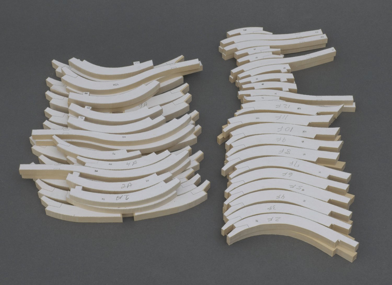
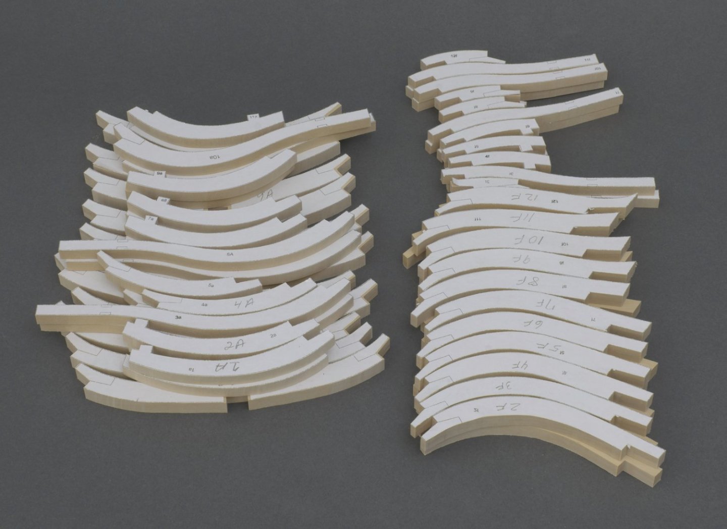
Square frames (pt. 2) Hi guys, Moving ahead I decided to cut out the remaining square frames from sheet and mill all 140 scarph joints. A real exercise in patience, like doing guns. Mike
-
Congratulations on a beautifully done Winnie!
-
I had the opportunity to visit Chuck last week. Photographs are always nice to look at, but being there is always better. At least when it comes to Chuck's Speedwell. He is using an advanced coloring technique to better mimic that of the contemporary model. The model has a subtle look to it where all the parts look proportional to one another and finely done. For example, the moulding that runs through the quarter badge is only 1/32' deep and the badges themselves are quite thin. I think it looks great! Mike
-
druxey, thanks for the tip!
-
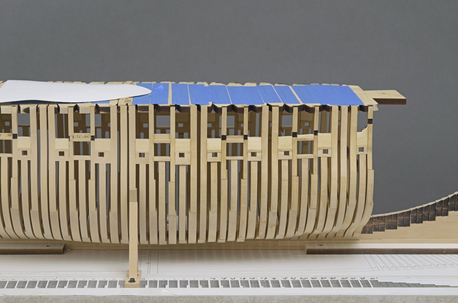
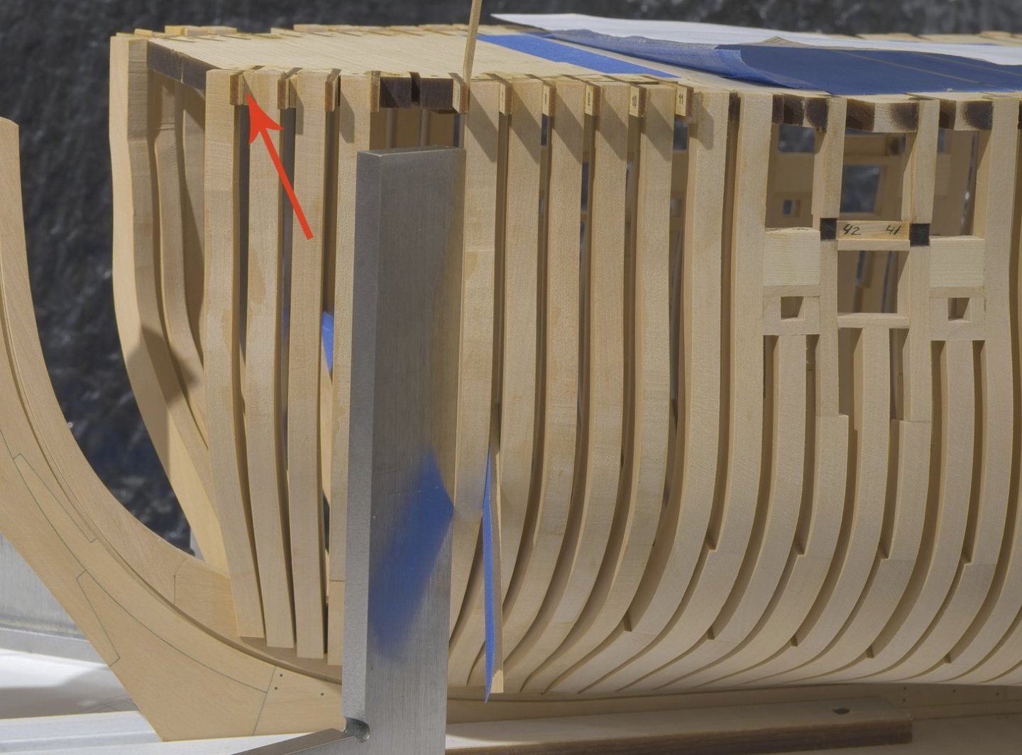
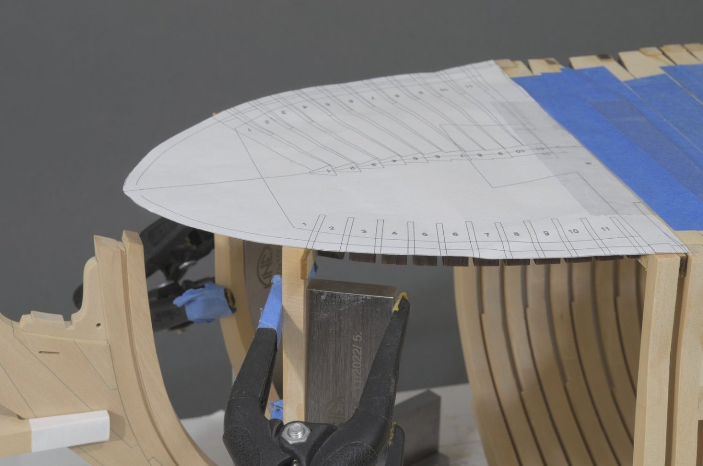
Bollard timbers More progress with the completion of the bollard timbers. I scratched these with the ongoing feeling that they might not work out for one reason or another. I did have to pull one along with the P1 filler piece, but luckily the glue hadn't set. What I found was that as meaty as these are at 9/32" that the wood would still develop a slight curl when using PVA. There was no good way to clamp pieces together. Generally I like to have some time to maneuver which the PVA allows for. In the end I went with slow cure CA. The paper template seen in the photo was stiffened with card stock. I flipped it back over the cant frames when I faired the curve of the top timbers, as seen from above. I can't stress enough how important it is to use it. It really does take the guesswork out of getting each side of the hull symmetrical. There is always more fairing to do though I think I'm close. Mike
-
I know exactly what you mean, been there myself. Trust me, your planking work will only get better. Still, you should be very happy with your result on the Winnie. Mike
-
Very nice, frank! you reached a milestone. You were willing to take things slow, and your efforts show that really nice work can be done if you take your time. I’m just curious, did you have a lot of throwaways? Mike
-
Thank you all for the kind words and for likes!
-
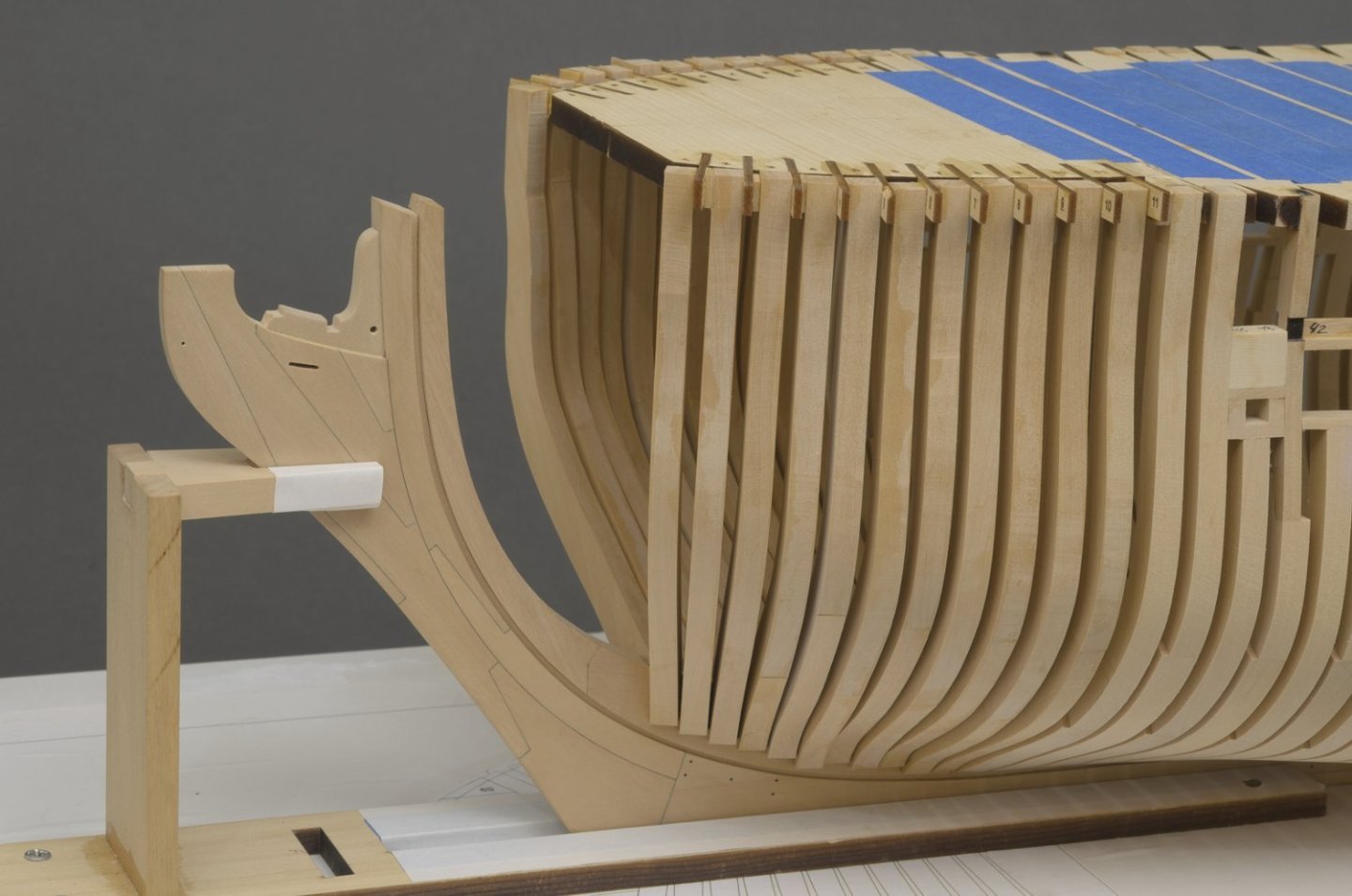
Adding the forward cant frames went rather quickly. Fairing them took me about three days, maybe more. Transitioning the deadwood into each cant frame had to be done carefully. I'm always finding the need to refine the previous fairing work after new frames are added, though less each time. I added the 3/64" P1 and P2 filler pieces to each side of the stem as well. Mike
-
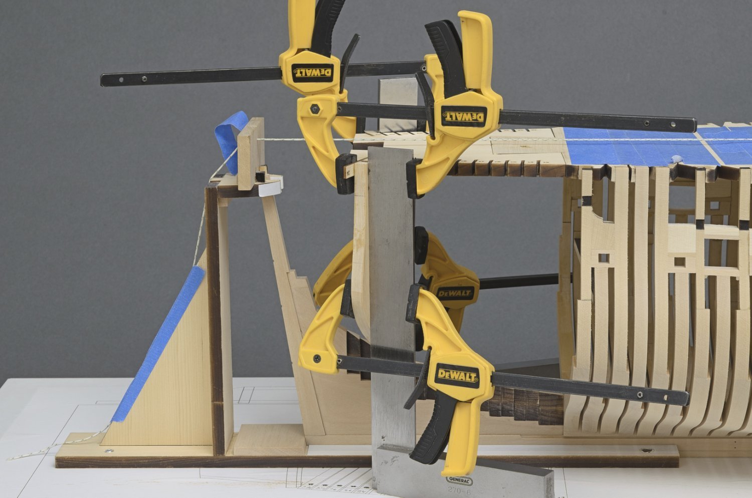
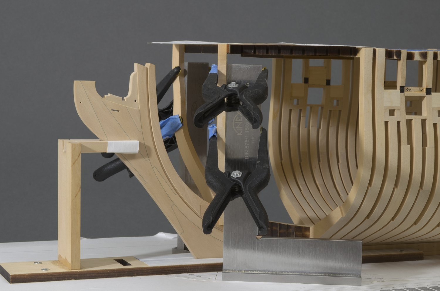
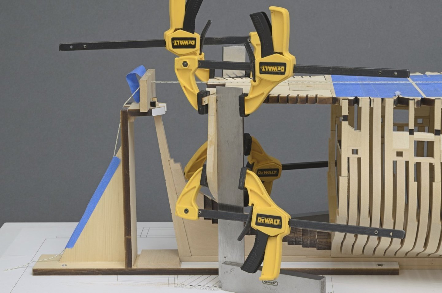
Keeping the cants vertical is really important. When the spacing started to get tight, I simply angled the machinist square to clear the frame already installed. A strip was used to hold the frame against the machinist square while the glue set. It was easy enough to get the right strip thickness by adding layers of painters tape. At the top of each frame, I added boxwood wedges to fill the gap between the frame and the numbered support strip. This ties everything together and should give a lot more support when fairing the cants. It's hard to see the true run of the cant footing since some of these cants are further away from the keel than others. Actually, the square frames where the same way, giving me the false impression that they would not fair in properly. I'm sure that things will work out okay for the cants as well. Mike
-
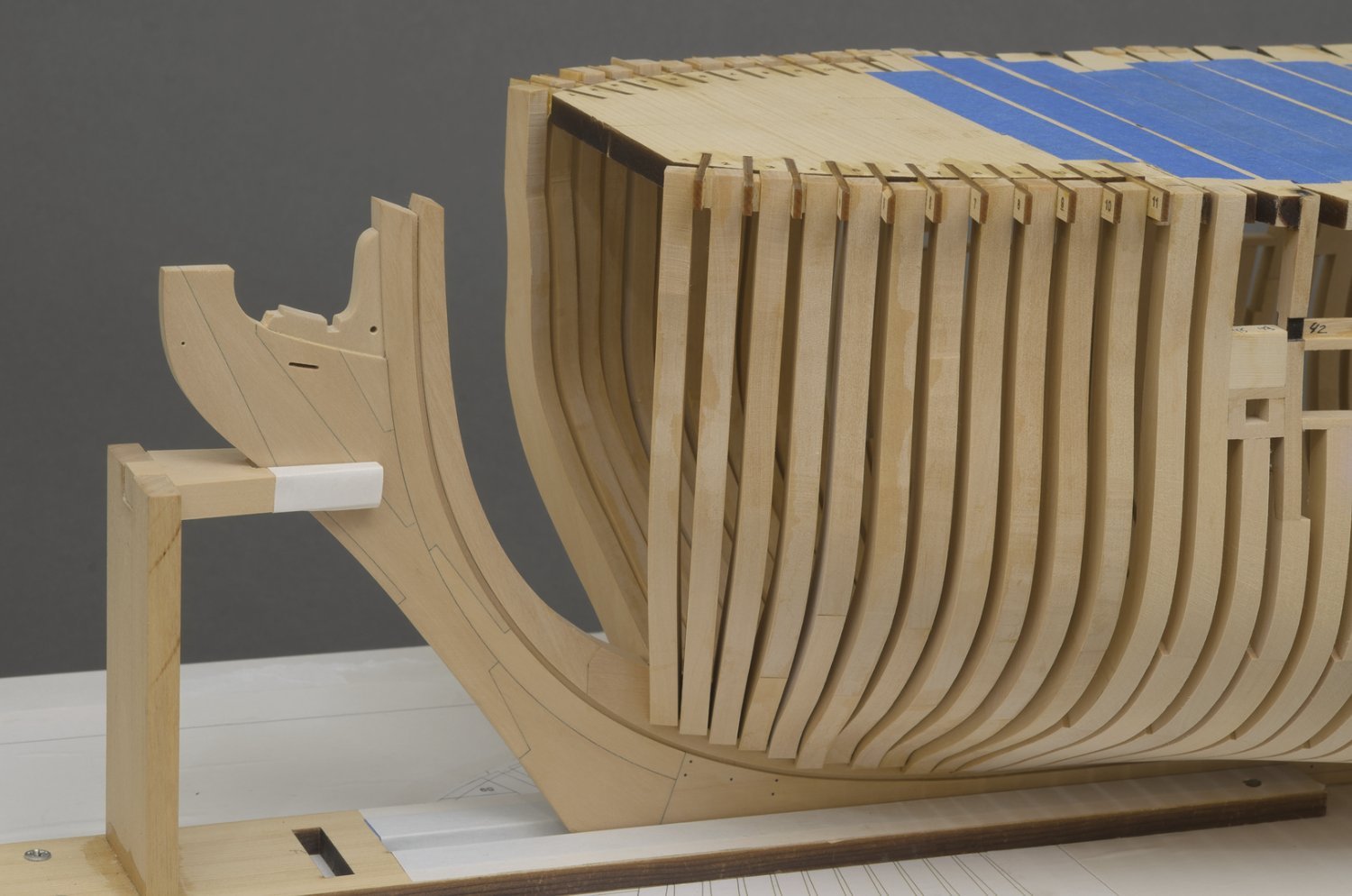
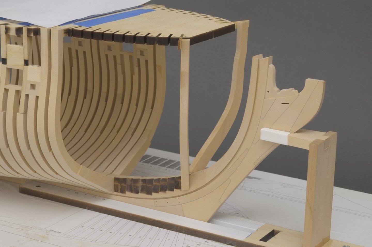
Cant frames (fore) Happy 4th everyone! 🎆 I started on the cant framing over the weekend. The first frames to go in are cant #1. They will also hold the front of the top jig in place. I made a slight adjustment to the foot of each cant in order to get a snug fit into the deadwood. While using a machinist square, I moved the frames outward a wee bit beyond the etched line on the strips in order to clear the bearding line. Not much, maybe 1/64" or even less. That was it. I was very surprised to see that the cants went in square to the build board. The paper template comes in handy as a double check on what you are doing. I actually prefer using it over just relying on the build board plan. The front of the template is at the aft edge of the rabbet as seen from above. Only ten more to go. Oh, yes I accidentally hit the top of the gammoning knee. Luckily it came off clean for easy replacement later on. Much later on! Mike

-
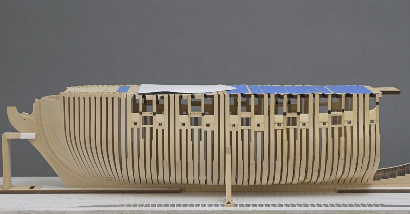
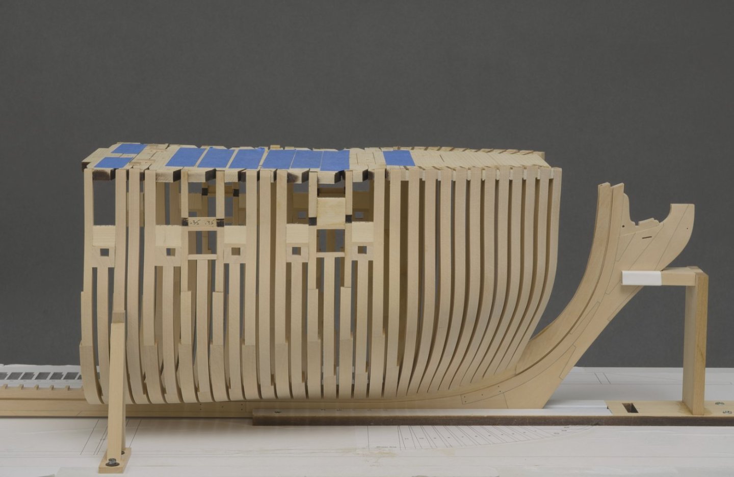
Hi guy's! A little over a month and 15 more frames added. Fairing continues after every 5-6 frames. I can't stress how important it is to fair as you go along. The hull shape is constantly changing, so the previously faired section needs additional work in order to match the newly faired section. Additional supports were added above the gun ports. Mike
-
Thanks, guys!