HOLIDAY DONATION DRIVE - SUPPORT MSW - DO YOUR PART TO KEEP THIS GREAT FORUM GOING! (Only 20 donations so far - C'mon guys!)
×


georgeband
-
Posts
301 -
Joined
-
Last visited
Content Type
Profiles
Forums
Gallery
Events
Everything posted by georgeband
-
 Tony, After a four year gap in model making I have been browsing your build logs again. My comment here is a bit late in the day but I must say I am delighted by the quality of your work which is an inspiration to me and others. Never mind your self-deprecating comments; your descriptions of the techniques you have adopted and improved are an education and the results shown in your photos provide ample proof that they are successful in the right hands. I look forward to following your next build. George
- 124 replies
-
- 2
-

-
- longboat
- Chaloupe Armee En Guerre
- (and 1 more)
-
I have looked up sail weights in Steel, pages 143-145. He lists 10 grades with number 1 the heaviest at 44lb for a bolt and number 10 the lightest at 15lb. A standard bolt is given as 38 yards long and 24 inches wide. One paragraph tells us that the six heaviest grades have 'at least 560 double threads of yarn'. I understand this to mean that what we call a 'thread' is actually two threads together, and there are 560 of these pairs across a 24 inch width. Technical term- these are the warp threads that run along the bolt of cloth. Other parts of this section say that doubled threads are also used across the cloth (weft threads). 560/24 = 23.3 threads per inch. The pitch between threads is about 1mm and on a model will be proportionately smaller. If you want scale size sail cloth using fine cotton lawn which is 240 threads per inch then your model will have to be at 1/10 scale or bigger! This is reasonable for a boat but for a ship in 1/64 or 1/85 there is a decision to make: live with the over scale thickness if you want a woven material, or use something like silkspan if you want the sails to be thin. Neither is perfect but if it gives a result that you like then be happy. George
-
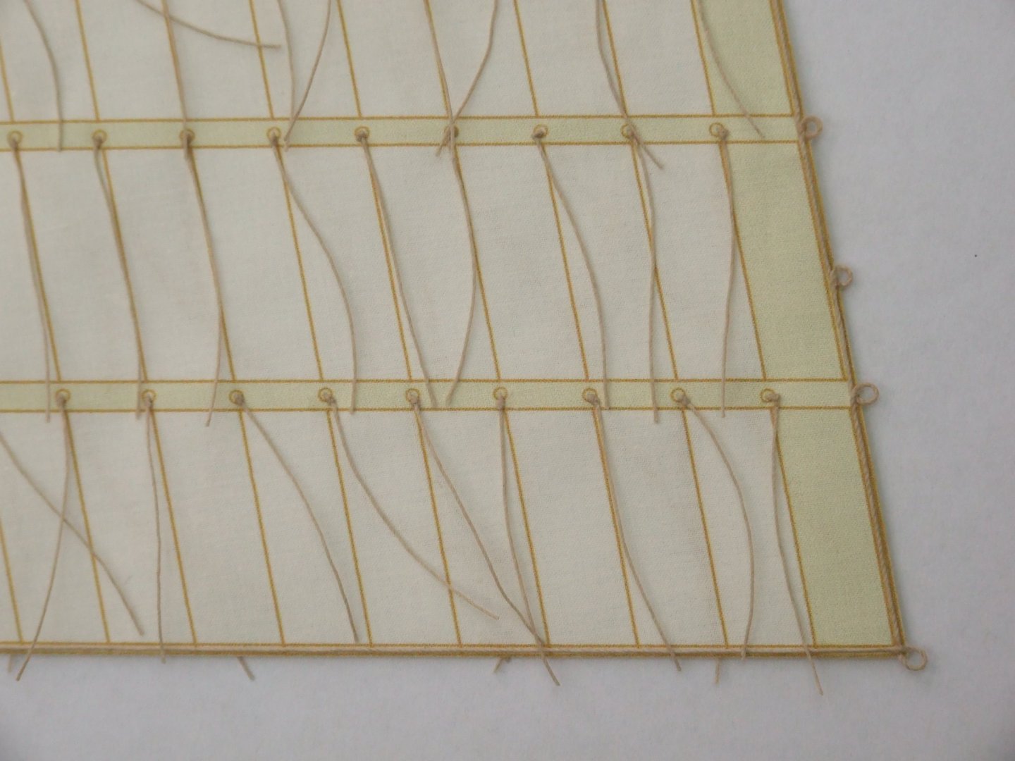
Allan, Ref your post #6 above. I drew the sails and dog ears on screen with all the seams as pale brown lines, then inkjet printed them on the finest cotton lawn material that I could find. This prevents one slip of a pen from ruining a whole sail. The material is intended for patchwork and quilters and comes in US letter size with a plastic backing. EQ Printables 9284. The thread count is 240 per inch which at 1/64 gives a pitch between threads of about 1/4 inch. Not quite a rope but still a lot thicker than a linen thread. The seam lines are darker than the sail itself because they have four layers of canvas and block the light more. At normal viewing distance the contrast between lines and background gives the right effect and open sails are nicely translucent. If you do want the sails to have a realistic scale texture then the silkspan approach looks better than what I did. It still leaves another problem in that the stiffness is too great for the weight and you have to build in the folds and drapes. That also applies to ropes that are not under tension and have to be coerced to lie in a smooth catenary curve. The photo below shows part of the gaff sail at a more normal viewing distance than the extreme close-up of the dog ears. All the rings around the reef points would have been difficult to draw by hand and an invitation to make a mistake. The bolt rope around the edge was glued on with PVA. George
-
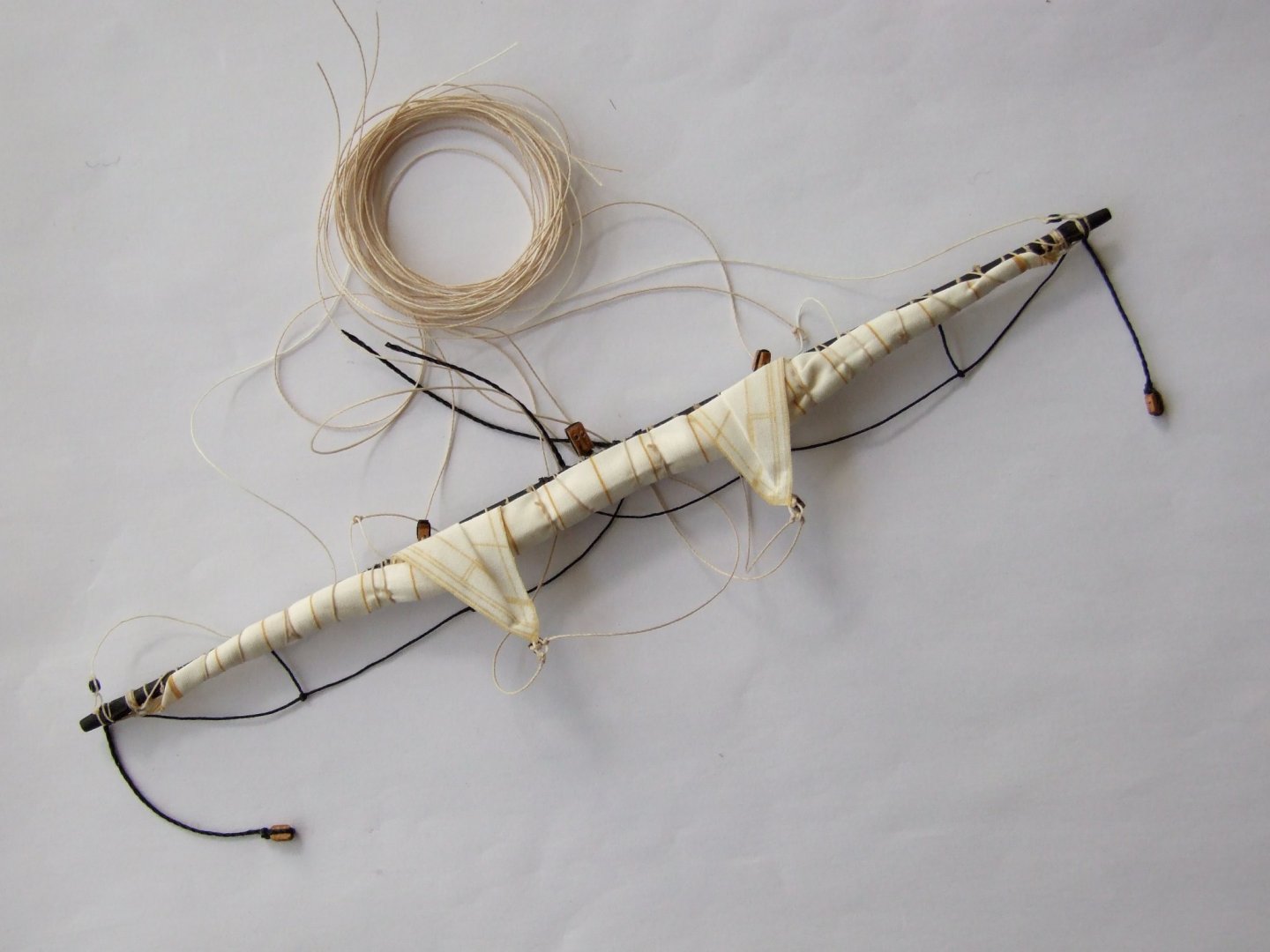
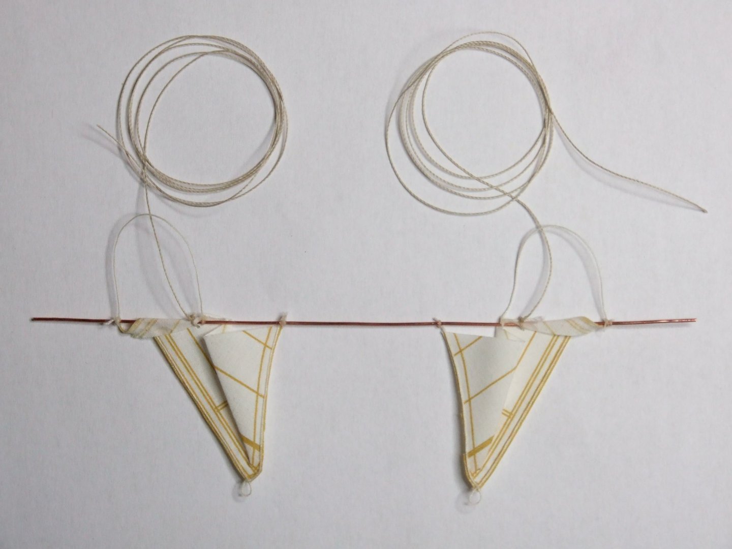
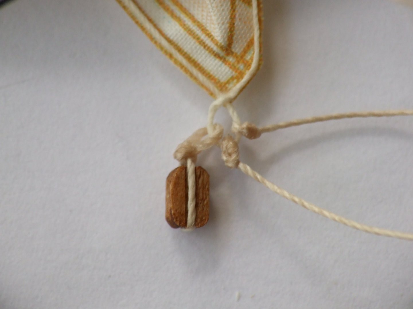
Tom, My interpretation of this problem rested on the way in which a square sail is furled. It is not 'rolled' but rather pleated and the final layer forms a skin over those beneath it. The furling action also brings most of the weight of the sail towards the centre of the yard (at least in the time of your Leopard). The lower corners of the sail stick out from the furled mass and were called dog ears. When a ship was sailing before the wind in extreme weather these dog ears were the only active sail area and were referred to as goose wings. On my model of Sherbourne I attached three ropes to each dog ear: the clew line, tack and sheet block. I also had a bunt line and bow line emerging from the skin by the dog ear. Henry says that the bow line was probably unhitched and I do not have any evidence to dispute this so follow his advice and have one rope fewer to deal with. The photo below shows the complete yard ready to be attached to the mast. The edge of the 'skin' is just below the visible edge of the yard itself and the dog ears rise up there and are bent over to hang down in front of the yard. I made the dog ears as triangles and mounted them on lengths of copper wire which was tucked among the pleats when furling the sail. On this photo the bunt lines have been coiled. The bow line is a loop which would have been between two cringles on the sail. This loop projects from the skin with the dog ear and I tied the bowline itself to the loop. The corner of the sail has a cringle and I tied a block and two ropes to it rather than trying to replicate the actual links which are complicated and hard to see at 1/64 scale. There is a fuller description on my website where you can also download a pdf file that has more photos. Here are links to both. https://www.grbsolutions.co.uk/ Sails.pdf George
-
Topsail schooner sail plans and rigging
georgeband replied to Dr PR's topic in Masting, rigging and sails
Phil, Thank you so much for providing all this detail. I am building HMS Whiting (based on Caldercraft Ballahoo) and have found extensive information from Admiralty drawings about the hull. However, the masts, yards and sails are a different matter. For these I have Petersson's book and four treatises on masting schooners. I have also copied the log book kept by her first sub-lieutenant. The mast and yard books present different rules so the sizes on my model will probably be set by eye and informed judgment. Fortunately I am not at that stage of building yet and can research a while longer. For the sail plan I will read your notes carefully then compare them with an Admiralty drawing for Adonis (similar but bigger...) and notes from the log book. That has its own problems with legibility but I have already seen orders about raising and lowering a ring tail sail. Once all that is sorted I can look at preparing a belaying plan. Lots to do. In your extensive research have you found anything which will transfer to a Bermuda built Ballahoo from 1805? I would be delighted to hear if you can add to the pictures I am trying to create. Best regards, George- 104 replies
-
- 4
-
-
- schooner rigging
- Topsail schooner
- (and 1 more)
-
Justin, Your copper plates are very impressive and add to the model. I am sure that they transform the impression she gives. I have a set of the Amati plates to use on a Ballahoo schooner (modified Caldercraft kit) and do not have any drawings for how they flow and align with each other. My concern is about how I should handle the stealers: near the bow I will probably taper some of the plates and at the stern I will probably fit in a few triangular pieces. The alternative is to change their angles a little, equivalent to bending a plank across its width. How did you deal with these issues? I would love to see a few close up photos of the bow and stern. Regards, George
-
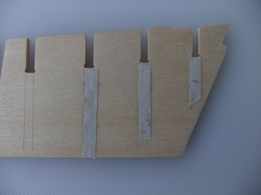
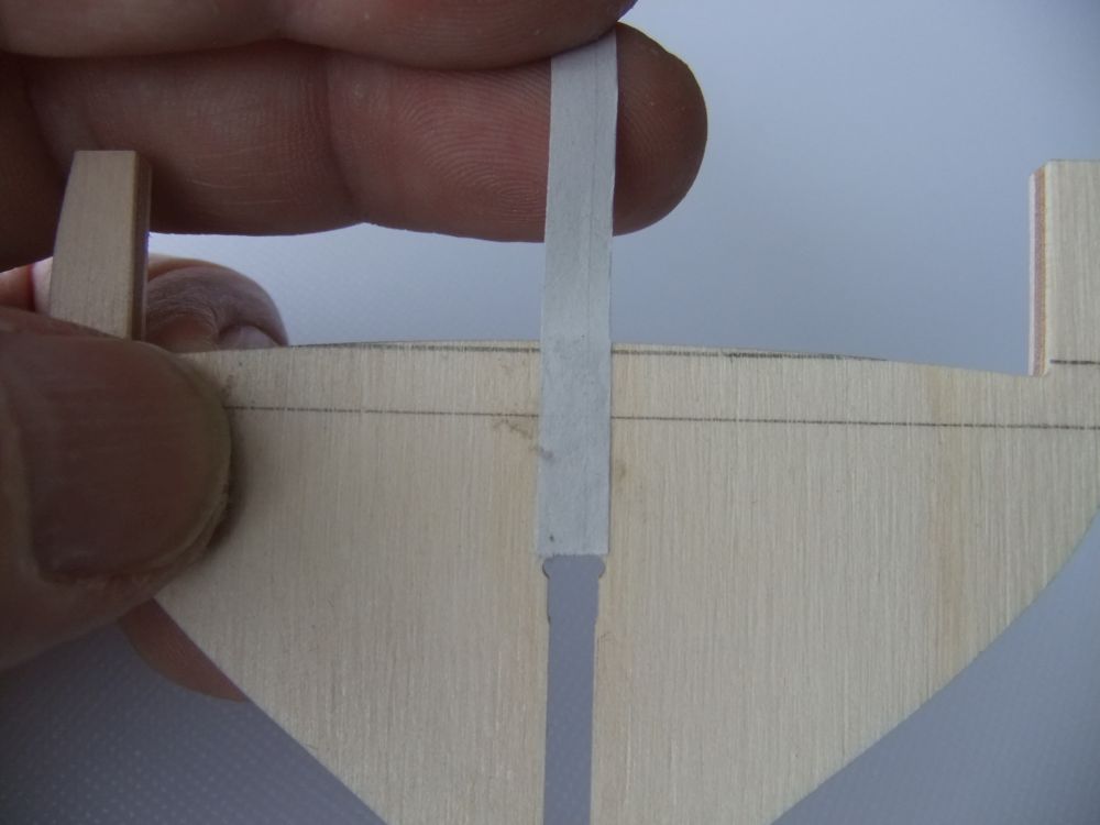
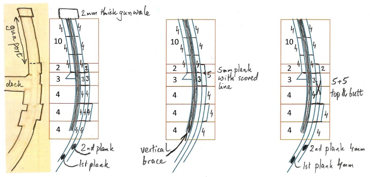
Bulwarks and wales... Here are my ideas for the second planking. The majority from the wales to the keel will be in 4mm walnut as supplied in the Caldercraft kit and I do not imagine any unusual problems here. The interesting bits are around the wales and then the bulwarks. The picture below has an extract from the Admiralty drawing ZAZ6118 with my pencil lines to improve the contrast. The printed numbers are the widths/ heights of the various sections in millimetres at 1/64 scale. (Apologies to people in the USA who prefer inches.) The lower part of the wale is quite distinct and I will represent it with an extra layer of 4mm walnut. The upper parts are not clear on the drawing and could be of different thicknesses. The differences are small, less than 0.5mm at scale, and could be indicated with a coat of paint. I have put three options that I am considering next to the scan. The first (on the left) uses planks that are 2mm, 3mm and 4mm wide. Some careful pre-sanding of the 3mm plank could reduce its thickness to make it sit deeper than the two next to it. The second option has a 5mm wide plank in place of the 2mm and 3mm which could be easier for construction. The third (right end) option replaces the 3mm and 4mm planks with top-and-butt pairs cut from 5mm wide stock. I am tempted by the top-and-butt arrangement because it looks good. However, it does not replicate the small change in thickness shown on the Admiralty drawing. I also do not have evidence which says that top-and-butt was used on this part of a small vessel, apart from the Marquardt reference above. Most of the standard references say that top-and-butt was used for the main wale and on this schooner I am not certain whether that means the 4mm plank at the bottom or the whole, thicker area. Has anyone dug in this patch before and found the answer? The bulwarks present a different problem because I did not use the ply sides from the kit. My plan is to bend some lengths of 4mm wide walnut and glue them vertically to the inside of the first planking. They will project 12mm above the top edge of the first planking and form the sides of the gun ports. I will plank them inside and out with 4mm wide planks: the bottom layer will be in continuous lengths with 2mm deep cut outs where the gun ports sit. The middle and upper layers will (probably) be from shorter lengths that fit between the gun ports. The novelty is that the outer layer is a continuation of the first planking. Has anyone got experience and words of advice about this method? George
-
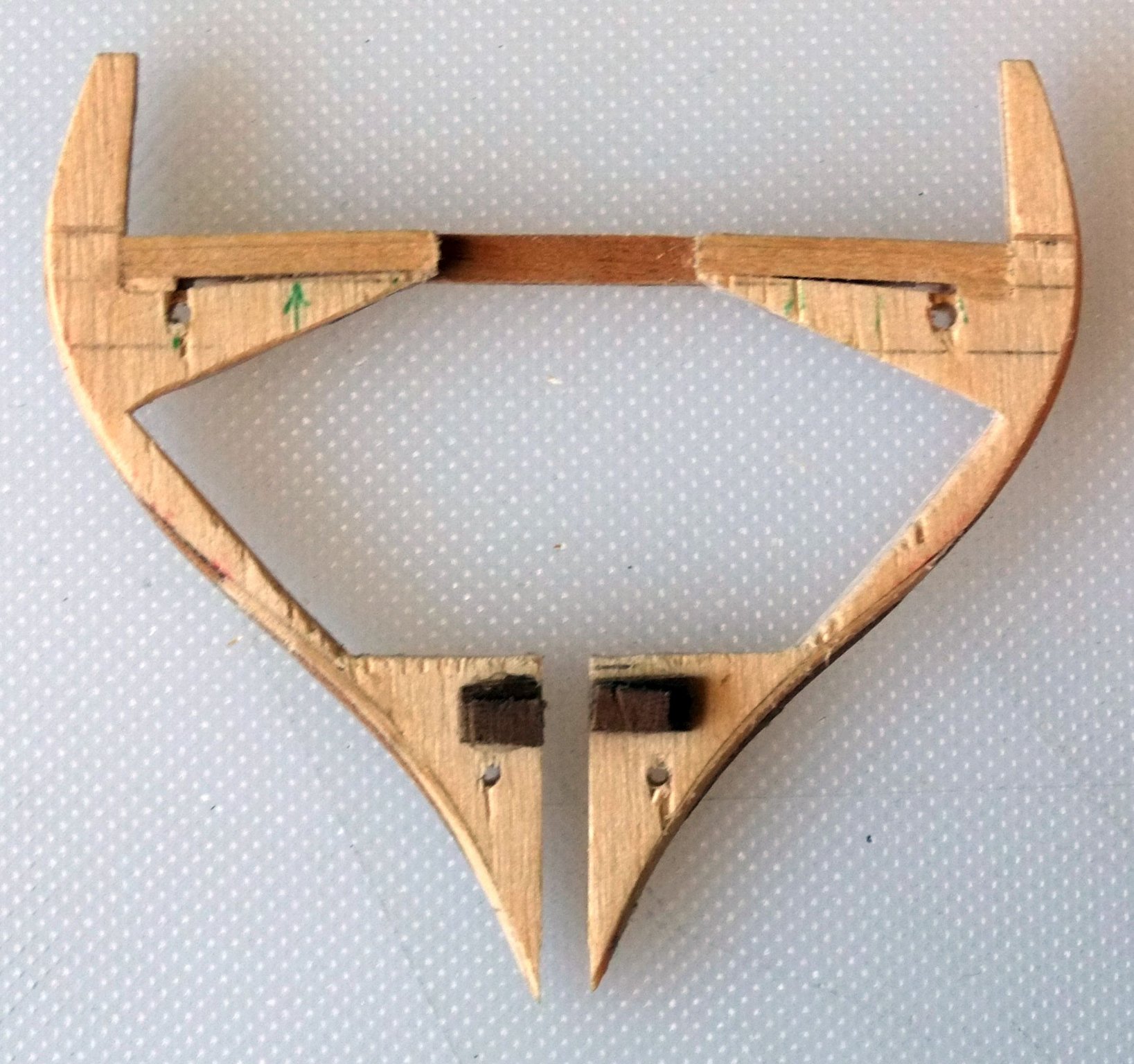
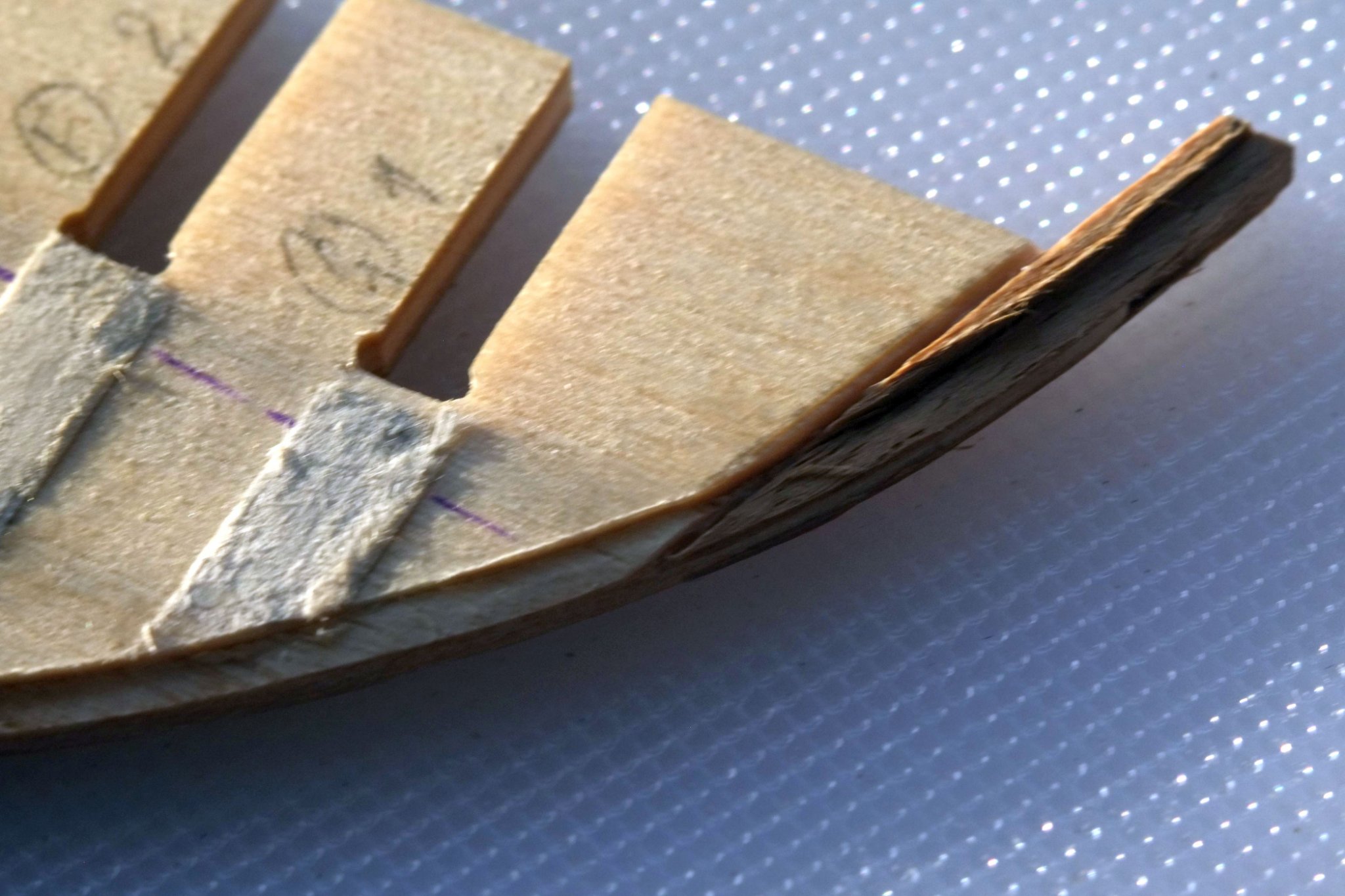
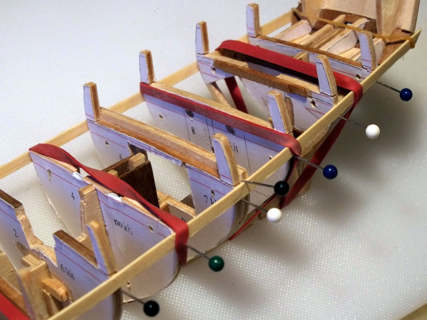
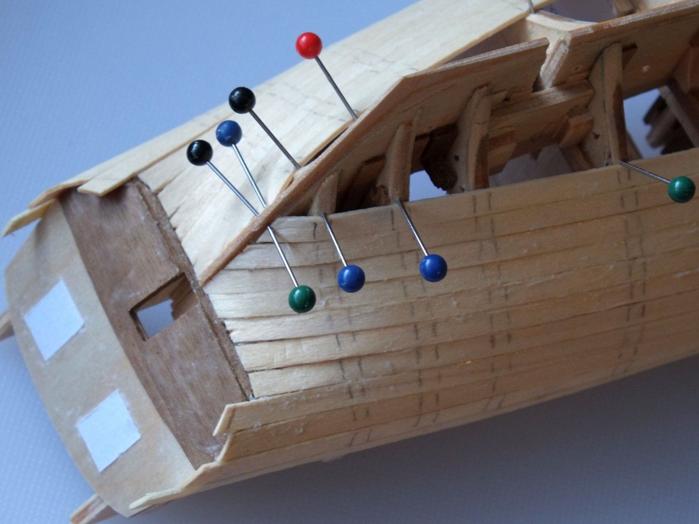
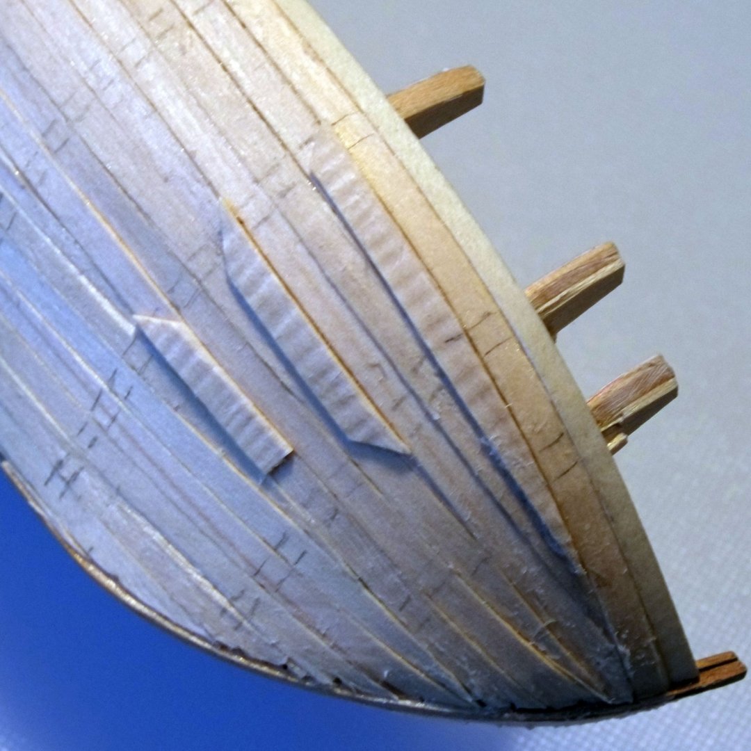
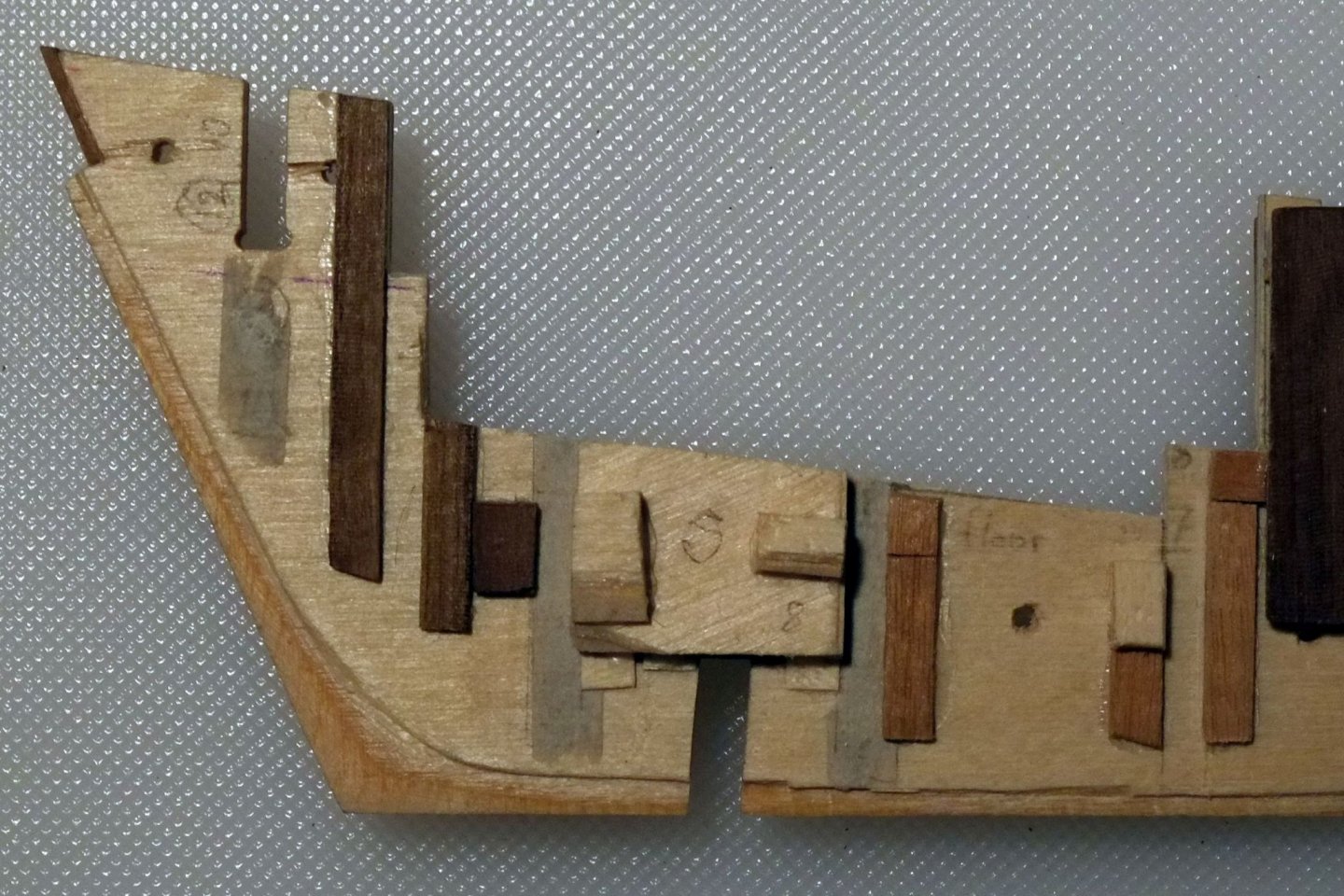
I have now fitted the first planking to the skeleton. Nothing particularly complicated here and it is mostly repeating the sequence of bend the plank and trim its ends, glue it in position and keep it in place while the glue sets. I set the datum line for my first plank with pins pushed into the bulkheads. The template drawings I had prepared have a couple of lines on them which show the wales and I used these instead of the ply bulwark pieces from the kit. Once the row of pins was firmly in place I prepared the first plank. Different people have their own preferred combinations of heat and water for bending: for lime wood I just soaked the planks for 15 minutes then bent them past the elastic limit to get them to shape. I put a drop of wood glue on each bulkhead then positioned the plank and held it with a couple of pins while I stretched strong elastic bands over the assembly. The elastic bands (courtesy of our friendly postman) provide firm pressure in the right place and direction, just make sure that there is a bulkhead beneath them otherwise that plank will bend where you want it to be straight. The other planks now have an edge to press against and be glued to. The first couple went down better with elastic bands and after them I could use pins alone to hold them down. I stuck the pins into the bulkheads at an angle so that they pushed the plank down and onto its neighbour. The picture above shows the stern tuck that you get if you follow the Admiralty drawings. The kit supplies a bulkhead and a transom for a square tuck which is quite different and I don't know why Caldercraft took the approach they did. The pencil marks on the planks show where the bulkheads sit and I find them useful when bending and tapering the planks. Quite a few of the planks at the bow need stealers. For the first planking I did this the easy way with simple tapers on the planks (simple does not mean a straight line taper, just that it goes to a point). I had expected stealers at the stern but there were only three per side that were big enough to need filling with little triangles of lime wood. Can you find them in the photo? The rear edge of the spine has a bearded rabbit to hold the hull planks. Near the keel the planks are nearly parallel to the spine so the spine is thin and the first and second planks will be sanded to give the correct total thickness. Near the counter the planks come in at an angle and I have put in a rebate (rabbet, rabbit...) to accommodate them. The transition between the two zones is either very complicated to mark and cut, or the ideal setting for a bodge job which looks good on the outside. Having spent many hours with a spreadsheet to calculate lines and angles for the bearded rabbit I am now tending towards sanding down to a desired thickness in the cross-over area. One mistake I made (several times) was to stretch some planks too tightly between the bulkheads instead of following a smooth flowing curve. These planks are recessed compared to their neighbours and I glued extra patches of lime wood over them to build up the thickness before sanding. I bent these planks to shape without heat or water, simply using round nosed pliers in little nibbles that show up as ripples on the photo. I have now sanded the hull, taking the opportunity of a dry spell to do it outside so that all the dust would blow away. Now I am waiting for a bright day to photograph it. The question that is bothering me for the next stage is the arrangement of the planks on the wales for the second planking. We have the Admiralty cross-section which helps but is not definitive about how the planks were fitted. I would like to fit them top-and-butt because it looks interesting. Marquardt in 'Global Schooner' says that the 'thick stuff' was often fitted top and butt and that is the best relevant advice that I can find. I will copy and post the Admiralty drawing with my ideas for how to model the second planking later. George

-
Sailor... Thank you for your comments. Some of the action takes place in NS around Halifax and Shelburne - is that near to you? HMS Whiting had a busy time around NS illegally press ganging in 1805 and Keith Mercer has written some excellent accounts of these histories. https://pc-gc.academia.edu/KeithMercer . My character joins Whiting for the next novel which is still only a faint image in my mind. George
-
Eamonn, I agree with your comment about the anchor stock looking too big. References such as Marquardt's 'Global Schooner' which go back to Falconer or Steel say that the length of the stock should be the same as the length of the shank. The anchors in my kit have a stock that is 50mm and the shank is 41mm so the proportions are quite wrong. Marquardt also quotes rules for the size of anchor and it works out that a Ballahoo should have anchors that weigh about 4cwt which is considerably less than the 12cwt in the kit. Their length is 7' 6" which translates to 36mm in our scale. I will probably buy a pair of Caldercraft's 3.5cwt anchors which are the right length, but it is a double shame that they provide the wrong size and with an oversized stock. George
-
Thanks for your message, Eamonn. I have been looking at your build and the recent discussion about serving the rigging puts me on warning that there is a lot to do here. I hope to shortcut some of my research by following what you have done on your superb build. My novel is set on HMS Leander from 1802 to 1805 and is a coming of age story. It has illustrations which purport to be drawn by the principal character. The grand finale is when a small schooner crewed by boys takes on a French privateer. I have learned a lot about publishing and am still trying to find a literary agent to promote it for me. George
-
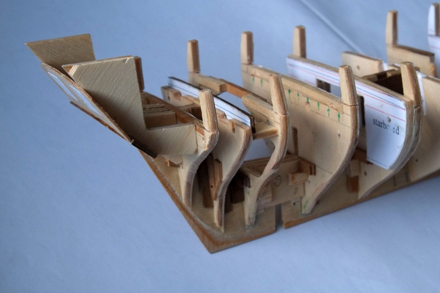
This build log for Whiting, a Ballahoo schooner using the Caldercraft kit, continues after a gap of nearly five years from when I started. Sometimes life gets in the way and mere cutting and gluing takes a lower priority. In this instance life was sometimes good (two wonderful grandchildren and finishing a novel), sometimes just time consuming (moving house and then building an extension), and sometimes not so easy. I have approached this build with the intention of making it as accurate as possible and showing a large part of the interior. The Admiralty drawings provide an excellent start and I have also spent many hours photographing log books for Whiting and then trying to read the handwriting. Currently I have just finished assembling the spine and bulkheads. The work included Drawing templates for the existing bulkheads to allow for steps in the height of the deck and errors in the camber of the deck and the curves below the waterline. Drawing templates for new bulkheads which are not in the kit. Adjusting the shape of the spine where it deviates from the Admiralty drawings. Adjusting the rake of the main mast as set by the spine. Cutting rebates into the spine for hull planking. Cutting slots into the spine for posts to use as stands. Reducing the size of the stem post, stern post and keel. Cutting out the spaces for the captain's cabin, the entrance lobby below the main ladder way, and the interior below the fore ladder way. The joins between the spine and bulkheads are complicated and a bit ugly here with blocks of wood holding things together. Rebuilding the counter and transom which are quite wrong in the kit. The next step is planking the hull which raises issues around the bulwarks and gunports and the details of the transom. I hope to continue fairly soon and not wait for another few years. Happy New Year, George


-
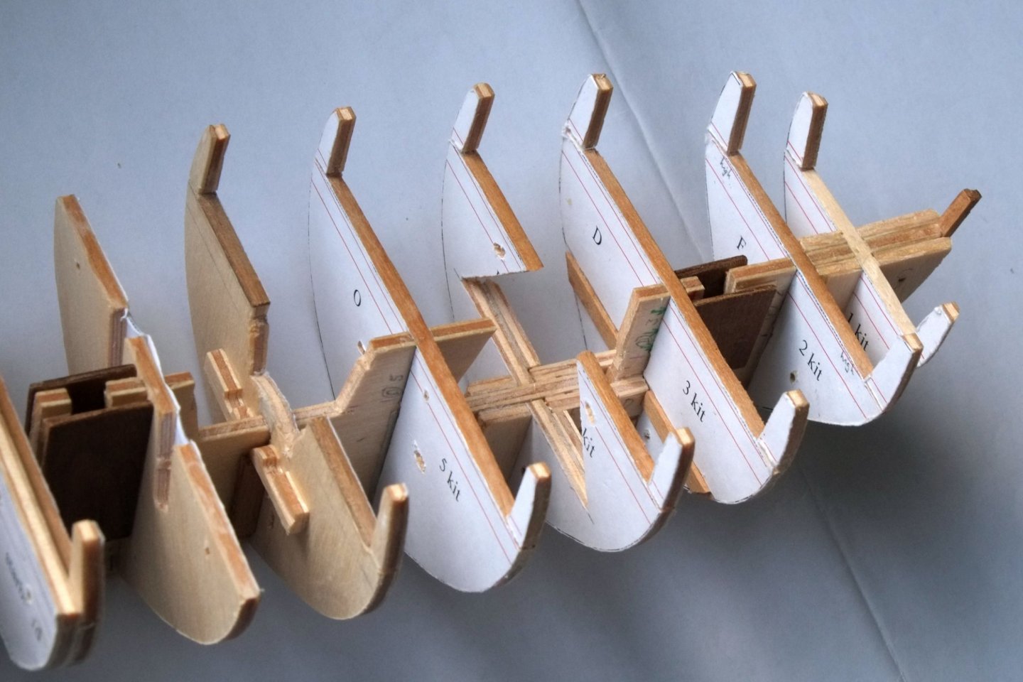
Cutting and gluing at last after a long break. I cut back the spine to match the Haddock drawing: the deck aft, the stern post, the curve of the bow, and the slot for the main mast. I glued in a couple of strips of 1mm x 5mm limewood into the slot, ready to cut back later to fit the mast. The raised deck above the commanders cabin will wait until a little later, as will other cutouts that weaken the spine. The slots for joining the bulkheads to the spine were too wide giving a sloppy fit. I glued a couple of layers of newspaper onto the spine and onto each bulkhead to thicken the parts and give a snug fit. I chose newsprint because it does not have the glazing of 'better' paper and should adhere well to the wood and also be less likely to delaminate. I have noticed this as a problem on previous models where ordinary paper splits into layers. Shaping the bulkheads continues to be a lesson in patience. I marked the parts by holding them over the profile drawings in Haddock (and Cuckoo) and then cut and sanded to shape. It became difficult to check the shape against the drawings so I drew a couple, cut them out and glued them to the bulkheads, and then had a line for cutting on the part itself. Much easier and I should have done that first. Then I checked my copied and reversed drawings and found that the maximum width on the fore sections did not match that on the rear profiles. The only way ahead was to redraw them all and make sure that they followed the profiles in the drawings properly. I did that, and then thought about what the Haddock drawings really show: the lines are the outer sides of the frames without the planking (the 'breadth as moulded'). The planking on Haddock is about 0.5mm thick (in scale) and I estimate that the double planking on the model will be about 1.5mm thick after sanding. I then drew new lines inset 1mm from the actual profiles as my cut lines. Next step is to print them, cut them out, glue them to the bulkheads and begin sanding or packing out the profiles. This time they will be right. George


-
I am trying to find one particular copy of Bowditch, and wonder if someone knows its whereabouts or even has it themselves. It is all part of a long research project to establish the history of HMS Whiting, the Royal Navy schooner which was captured twice in 1812. While browsing through the interweb I found an extract from Goodspeed's catalogue of second hand books for 1959. It is only 'snippet views' but I managed to put together enough to show that the copy was originally owned by 'Woode Langdon Captain of the Brig Drummond at Portsmouth in Virginia' who gave it to Lewis Maxey, commander of Whiting. Whiting was the first capture of the War of 1812. She was released from her capture, sailed away and was then captured by the French privateer Diligente. The copy of Bowditch was then possibly returned to Langdon. The book has hand written entries by Langdon and Maxey and annotations to a map opposite the title page. If anyone here knows where to find this copy, and can get me photos of the marked up pages, then I will be most grateful. I know that it is a very long shot to try to find one particular copy of a book, but it is probably sitting on a shelf somewhere. George Bandurek
-
- 2
-
-
Superb execution, but what really impresses me is the detail planning that precedes the constructional steps so that you pre-empt the problems. One question: what is 'Gesso'? It is not something I see in the shops in England. George
- 641 replies
-
- 2
-
-
- greenwich hospital
- barge
- (and 1 more)
-
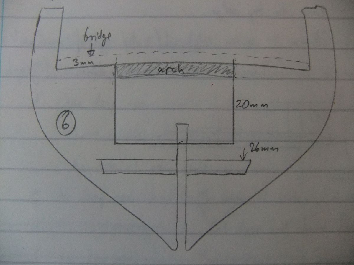
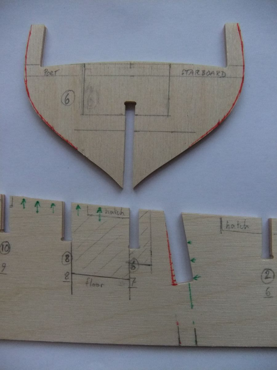
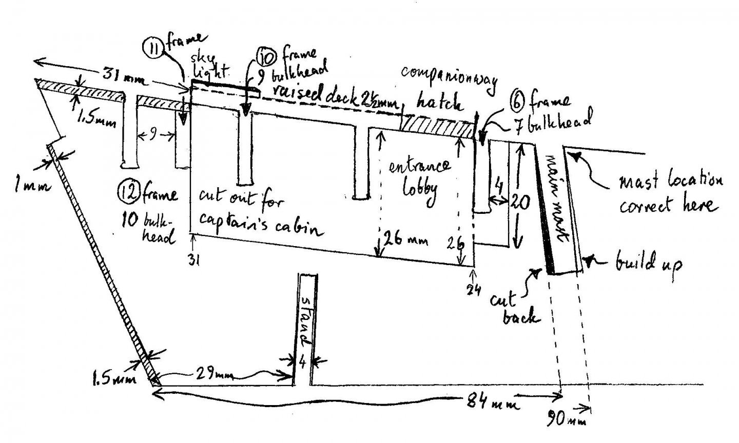
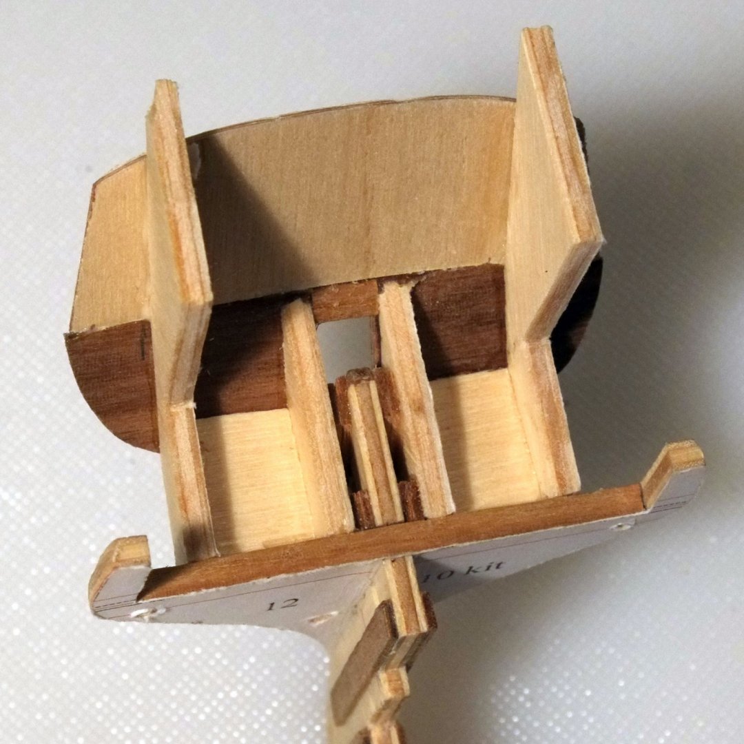
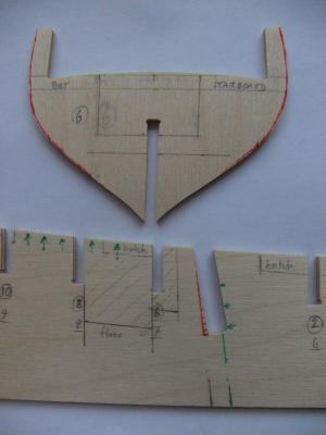
Another week goes by and I have still not cut wood or applied adhesive. But I have been busy interpreting and measuring and planning, which should make the build a lot smoother when I finally begin. Bulkheads I used the sectional drawings in Haddock ZAZ6116 and with some copy-paste, cropping and reflected images I created full sections instead of half sections, making it much easier to compare the kit bulkheads. The useful extra step was to mark the position of the top of each deck on the drawing so that it was easier to align the parts. The photo shows in red where I will have to trim back the kit parts, mostly above the waterline. Section 12 on the drawing, bulkhead 10 in the kit, is somewhat oversize compared to the drawing. Section D, bulkhead 3 in the kit, has two sets of lines on it. The inner set are a close match for the drawing, but the bulkhead is a couple of mm too far aft in the kit. I now intend to leave the mounting slot as it is in the kit which means that the bulkhead should be a little bigger than the drawn section: the outer set of red lines are my cutting guides. The horizontal pencil line about 5mm below the deck marks the edge of the main wale to make planking easier later. Deck camber The deck on the bulkheads has a much steeper camber than that shown on ZAZ6118 especially near the bulwarks. I will pack the deep gullies with some scrap wood and then sand to shape to make them a bit flatter. According to the drawing the centre should be about 1.5mm higher than the edges at the waterways. Entrance lobby Section 6, bulkhead 7 in the kit, requires major surgery because I want to leave the 'entrance lobby' visible through the cover over the hatch. There is a large asymmetric hole in it, the floor and ceiling are at different heights on either side, and it will be fragile for a while during modifications. I will cut a rectangular hole then build a couple of bridges/arches over it to represent the deck beams. (The height from floor to ceiling is about 20mm in the main hold where the crew live. This translates to 1.28m or a bit over 4 feet, and even lower under the deck beams. Hardly comfortable.) Ears on bulkheads The kit bulkheads have ears or tabs which are used to temporarily hold the bulwarks and then should be snapped off. The bulwarks have a curvature (tumble home) which is difficult to achieve with the supplied ply pieces and I am considering another approach: Finish the double planking of the hull Bend some 1x4mm planks and use them as frames, glued upright on the inside face of the hull planking Plank the outside faces of the uprights Plank around the gunports on the middle layer Plank the inside faces of the uprights The total thickness is 3mm if I use 1mm planks and is only slightly over the true thickness shown on ZAZ6118. The steps at the wales will, I think, effectively mask the fact that the hull is double planked but the bulwarks are single planked on the outside face. Has anyone tried something like this previously? Is there something that I have missed? (I still need to plan the positions for a couple of slots in the bottom edge of the spine for mounting rods, so not quite ready for building yet.) George

-
The evidence for mast tackles being used for catting and fishing the anchor is certainly there, and the picture from Luce that Juraj found sums it up nicely. I am not sure what would be done to haul in the main anchor cable though, and it could be deck tackle or the mast tackle. My own thoughts are that deck tackle would be used because it lines up naturally with a hawse hole. On a model it does not really matter unless you want to show the anchor being weighed so it is a question that we can duck quite easily. I still would like to know though. I have put some references to 'treatises' on the subject in another thread. http://modelshipworld.com/index.php/topic/12399-schooner-haddock-cuckoo-ballahoo-drawings-windlass-and-catheads/#entry381752 Gregor, you mentioned above that the bower weighed 390kg. I have found on Google that a man can pull 75lb, or about 35kg. Factor in x4 mechanical advantage from a pair of blocks and you get 140kg before any losses from friction. A team of four men could lift that anchor with power to spare! Lovely looking models you are building. I wonder if someone will offer a laser cutting service, in the same way that photo-etching can be done for you. George
- 121 replies
-
- 4
-
-
- la jacinthe
- schooner
- (and 2 more)
-
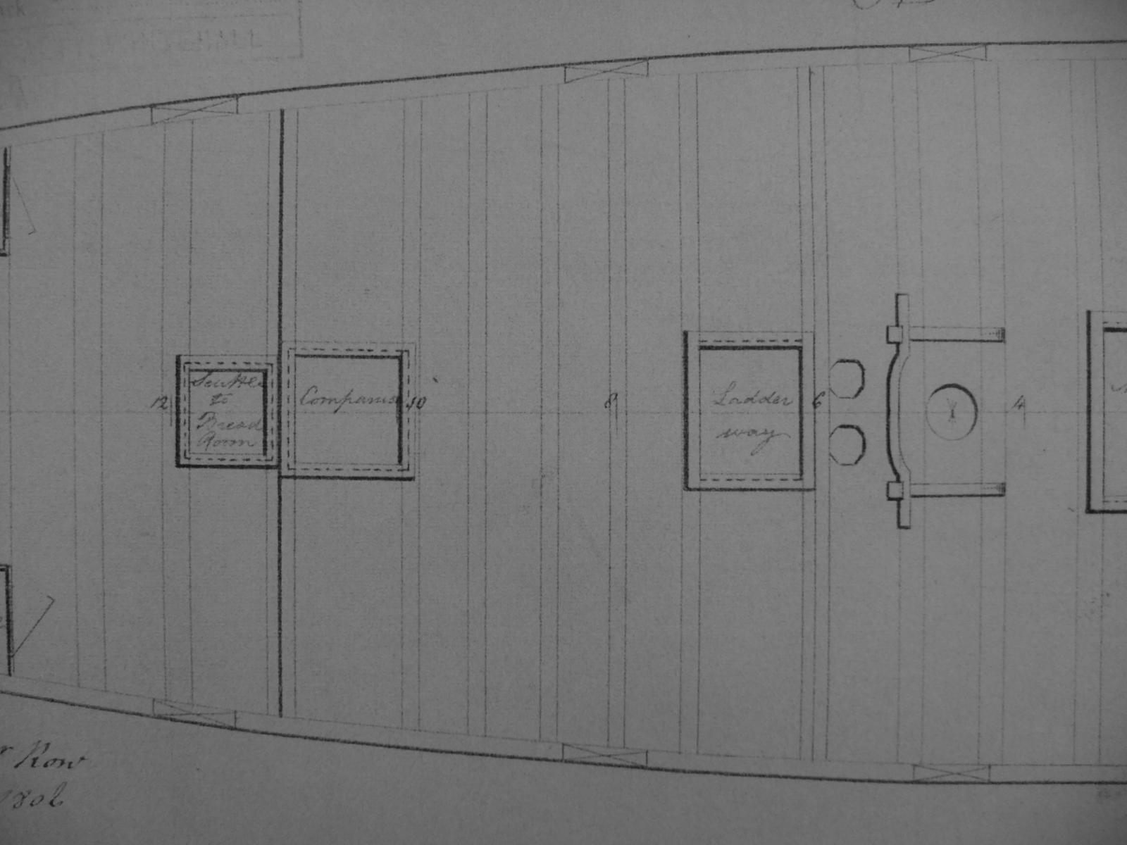
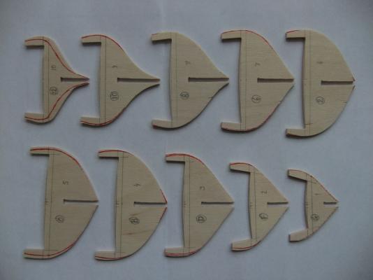
Thank you all for your comments. I had thought that this build would be well defined because of the abundant plans, but it is not so simple even when documents exist. The NMM drawings that I have downloaded are (all ZAZ numbers) 6110 Lines originally sent to Bermuda 6111 Early variant, side view 6112 A picture as much as a drawing, with a sailor and a boat and other bits. Not certain if it is a Fish class, but looks very similar. 6113 Lines sent to Bermuda, side view 6114 Yet another variant, side and plan 6116 Haddock side 6117 Haddock plan 6118 Haddock section 6320 Cuckoo and Wagtail side and sections My kit arrived from Model Dockyard last week (thank you to Nick Tonkin for quick delivery) and I have checked that all the pieces are there. I have also compared the central spine and the bulkheads and the stem and keel and rudder post with the Haddock and Cuckoo profiles and it is not all good news. The spine is mostly the right shape (!) and it lies well over the drawing if you align the fore mast, and the lower edge with the thick keel line, but it will need some changes and I have marked them below. The bow has to be cut back The stern has to be cut back The top edge is too high near the tiller and too low over the commander's cabin The counter and transom will need work later The angle of the main mast is wrong. I guess that Caldercraft made them parallel A couple of bulkhead slots have to be nudged along. In addition to the remedial work I will make cutouts below the hatches, and a big space for the main ladderway. I will also cut a couple of slots in the bottom for mounting points (brass tube to support the model and carry fibre optics for internal lighting). I would like to show the fore ladderway too but it is right over one of the bulkheads and I might leave it closed. The bulkheads are mostly OK compared to the sections on the drawings. A couple near the middle, 0 and 2, are too wide and most are too deep at the keel. Section 6 matches the drawing but is a little too far forward and will need to be made wider. It could be moved towards the rear, but is in the right place for its rear face to be the wall of the 'entrance lobby' so I will make it a little wider. Similarly, section D is the right shape but needs to be moved forward. The rearmost section, 12, is just wrong. (I have used the labels for the sections on the Haddock/Cuckoo drawings and not the kit numbers for the bulkheads.) The fit between the spine and the bulkheads is very loose and will need to be packed, probably a couple of layers of ordinary paper will do the trick. The walnut pieces for the stem, keel and stern post are well oversize. I will replace the keel with a piece of 4x4, cut down the stern post, and probably use the kit stem as the basis for a new one. The outside edge of the stem is not a smooth curve and you can see how it was approximated by four sections: sloppy design of the CNC cutting plan. The bulkhead at section 12 shows steps in its 'curve'. Bearding and rabbets to come. I will probably concentrate on the bearding and trim back the spine to allow for the thickness of the planking to achieve a finished thickness of 4mm. The stem, keel and stern post can then be glued on. Comments on this approach? Final point about the deck furniture. There is another thread about gunports where the discussion shows that they are not square. On Haddock there are lots of lines on the side view and it is easier to look at the plan view, and on the Cuckoo drawing, to decide which are the sides of the gunports. They are mostly perpendicular to the deck but not always. The drawing also shows hatches and the cover over the main ladderway (green on the photo) and these all follow the lines of the frames. So the carpenter building Cuckoo on the slips would have a horizontal keel, vertical frames, and according to the drawing the sides of the cover would also be vertical, while the roof slopes from rear to forward. Surely this cannot be right because when the schooner is afloat the sides of the cover would be sloping back, it would look a mess and the doors would be a right pain. Perhaps the cover (and hatches) are built after launching and the carpenters who work on a floating deck set their verticals with a plumb line, or with a set square perpendicular to the deck, and ignore the lines on the drawing. Building should start next weekend unless my wife has arranged some social engagements. I don't expect rapid progress on this log! George
-
Juraj, Thanks for the link about La Jacinthe which I have not seen previously. I find it reassuring when other drawings support my conclusions! There is another thread that is about windlasses and catheads, where I have given some calculations about how many men are needed to raise an anchor. I estimate that one man can pull about 200lb (call it 100kg) using a set of blocks that gives a x4 mechanical advantage. A one ton anchor is quite achievable. This link should take you there, or just search for 'windlass'. http://modelshipworld.com/index.php/topic/12399-schooner-haddock-cuckoo-ballahoo-drawings-windlass-and-catheads/#entry380007 George
-
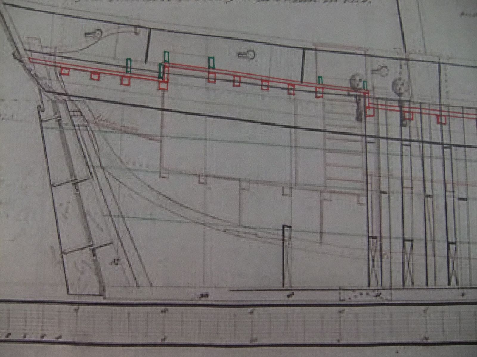
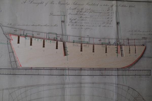
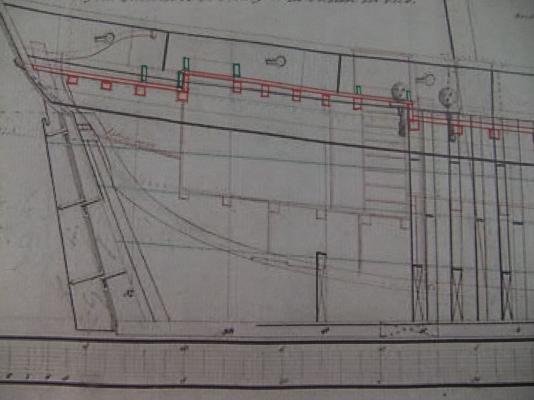
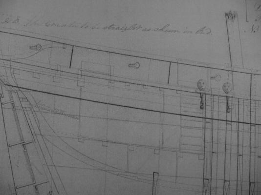
Juraj, I have not come across a windlass on the lower deck on other ships, so would suggest that this is unlikely. Larger vessels sometimes have two capstans, one above the other on the same shaft, so that more force can be applied to raise a heavy anchor, but I have not seen a single capstan below the deck. Part of the problem would be friction where the anchor cable is taken around a bend where it is fed down into the lower deck. The low ceiling height would also limit the length of the bars to turn the windlass, making it even harder to use. The other issue for Haddock is that the drawing shows no windlass above or below deck. I like your creative solution to the problem of 'no windlass', but unfortunately I don't think it would work. (Is this where someone finds a photo of a ship that has a buried windlass?) I have marked up a drawing of Haddock in red to show where the steps in the deck occur. They can be found fairly easily by looking for the cross sections of the deck beams. There is a NMM drawing for Cuckoo which shows the same features a little more clearly (it is meant to be a copy of the Haddock drawing sent to another builder in England). The photo also shows the various openings in the deck in green. The plan view of Haddock shows the deck beams, and the steps are where two beams are next to each other without a gap. If you want printed copies of the NMM drawings then copy the images from the NMM website and paste them into Word. You can then change the size of the drawings to get the scale you want. They do not quite fit onto A4 paper in 1/64 scale. George
-
It is very reassuring for me to see the Haddock drawing above from daves. I have been looking at this drawing for a long while and the varying sizes and shapes of the gunports did not look right, but I have to trust the shipwright who measured the schooner and drew the lines. Equally interesting is how the original build in Bermuda was altered by the people at Portsmouth - the fine dotted lines show the changes. George
-
Gregor, I have the same question about a windlass (and cathead) for the Ballahoo class schooners built in Bermuda. The drawings for Haddock at the National Maritime Museum do not show the windlass, but an earlier drawing does. I will have to go deeper into the references on seamanship to see if there are any clues there. George
- 121 replies
-
- 3
-
-
- la jacinthe
- schooner
- (and 2 more)
-
Tony, Kester, Thanks for your comments. I think it is right that the anchor cables enter through the corners of the main hatch; that is what I intended to say but was probably not very clear. The reasons you (Kester) give are a good justification for what feels right to me. The plan drawing for the lower deck on Haddock does label 'cables' at the sides, midship. Christmas celebrations will keep me away from the laptop for a while. Enjoy your break. George
-
I will be using the Caldercraft/Jotika kit of the Ballahoo schooner (Fish class) to build a model of her sister schooner Whiting. Why Whiting? Because she has an interesting history that I have researched in depth and I continue to study log books and other records. We are blessed with several drawings of the Fish class and their fore-runners at the National Maritime Museum and the drawings of Haddock in particular are excellent (ZAZ6116 and ZAZ6117 are the best two). I am now trying to interpret some features on the drawings and already have several questions about aspects that confuse me. I hope that some of the experienced shipwrights here can help. Height of the deck This is a big issue where the Caldercraft kit seems to make a major simplification. The kit has a level deck from stem to stern, but the drawings show that the deck is higher over the commander's cabin and the 'entrance lobby'. The side profile is a bit fuzzy but the deck planking and the sections through the deck beams show where the deck is higher. The plan view shows where there are pairs of deck beams at the steps, one at the low level and one at the high level. Is this something that Caldercraft and other builders have missed, or am I misinterpreting the drawings? (There are a couple of photos below that show extracts from the drawings.) Windlass and catheads The drawings do not show a windlass which is plausible for the size of anchor that this vessel would have carried. I have read that a couple of blocks would be set up in place of a windlass to raise the anchor, and then more blocks for the final lift because there are no catheads either. It all seems reasonable, if hard work for the crew, but an alternative explanation is that the drawing does not show the windlass or catheads but they would be fitted anyway. The builders might be expected to know to add these items, in the same way that they know about masts and yards even though the drawings do not show them. (There is an old saying that 'absence of evidence is not evidence of absence.) Any thoughts? Holes in the deck for anchor cables There are various names for these holes (Navel pipes?) which were used to route the cables from above deck down to the cable tier. The Haddock drawings do not show any and I guess that this is correct, the alternative being to cut away the fore corners on the grating over the main hatch. I suspect that the holes in the deck are later practice but have no real evidence to support this assertion. Does anyone have information from contemporary models or paintings? More to come later... George Bandurek (Previous model is Sherbourne, completed 5 years ago)

-
'Billy Ruffian' by David Cordingly is an enjoyable history of the Bellerophon, find it on Amazon or other places. My memory served me badly about the heights of the crew: the average was 5 feet 5 inches and none was above 6 foot. One was under 5 foot tall. George
- 188 replies
-
- 1
-
-
- Sherbourne
- Caldercraft
- (and 2 more)