
HOLIDAY DONATION DRIVE - SUPPORT MSW - DO YOUR PART TO KEEP THIS GREAT FORUM GOING! (Only 72 donations so far out of 49,000 members - Can we at least get 100? C'mon guys!)
×


Beef Wellington
-
Posts
2,249 -
Joined
-
Last visited
Reputation Activity
-

 Beef Wellington reacted to flyer in HMS Bellerophon by flyer - FINISHED - Amati/Victory Models - scale 1:72
Thank you, Alan.
To reduce the sail area this way was just a random idea which for once seems to work.
I'm afraid I'm unable to express the real amount of fun I had setting up all those lines - there might be readers of minor age. Frankly, it wasn't too bad but a bit tedious.
After seeing my photos I had to start - as it very often is the case - to rework the sail stowing. The starboard clew looked to loose and was tightened.
Thanks again for the positive feedback. It's always a big motivation.
Peter
-
Beef Wellington reacted to AON in HMS Bellerophon by flyer - FINISHED - Amati/Victory Models - scale 1:72
I find it interesting how you reduced the sail area... lowering the head, as I had seen this once before where the fellow scalloped the foot.
The end result is all that matters, and yours look pretty darned good!
Well done. You taught me something today. Thank you.
I imagine play rope snugging tag is as much fun as you make it out to be
-
Beef Wellington reacted to flyer in HMS Bellerophon by flyer - FINISHED - Amati/Victory Models - scale 1:72
mizzen topgallant yard and sail
According to my sail plan the mizzen topgallant sail is furled. Zu Mondfeld recommends to reduce the area of furled sails by about one third - to get a smaller coil of sailcloth.
This I followed and made a smaller sail, however with the same width of head and foot. Seams were penciled on and the hem was glued as usual, but no reef bands ore linings were put on. Also the boltrope covers only the head and the clews to further reduce the bulk of the furled sail.
The sail was then bent to the yard and tie, clew lines and simplified bowlines added. Now the sail was furled as tight as possible - but no harbor stow fit for an admirals inspection - and bent to the yard. The clews are hanging down on the forward side as seen on various illustrations.
The yard was put up with its tie and fixed to the mast with a simple truss parrel according to Lees. A whole arrangement with parrel ropes, rips and trucks - as shown on the kits plans - seems to me too bulky for such a light spar and out of proportions.
Now lifts, braces and sheets were installed and balanced against each other to have the yard horizontal and braced parallel to the topsail yard and the crossjack. The clew lines were set up to fix the clews against the pull of the sheets.
Each pull on one line of course sets up the balance and requires adjusting of several other lines - a heartwarming procedure which gives a lot of joy and generates a peaceful mind. (...)
The bowlines were set rather taut and help to fix the position of the yard.
Not all belaying points were marked on the plan and I had to change a few and find some new ones. As far as possible I used Lees as a help but sometimes I differed and looked for a simple and yet logical solution.
Lines were only provisionally belayed until all lines and forces were balanced (or nearly so) and then fixed with diluted white glue and the ends coiled up.
Now the mizzen mast is fully rigged except for the flag line and the next step awaits me - the mighty main yard with its furled mainsail and as an extra the stowed yard tackles.
reduced sail marked in blue on the plan
first side of sail marked on cloth
sail with lines attached - ready to furl
yard with furled sail, ready to hoist
topgallant yard in position
mizzen mast with all spars on
the poop deck gives now a properly busy impression
-
Beef Wellington reacted to flyer in HMS Bellerophon by flyer - FINISHED - Amati/Victory Models - scale 1:72
the new crew from Vanguard Models
After seeing Chris Wattons crew figures I had to try and hire a few of them. In my opinion, they surpass all expectations. The lively and individual stance of the figures makes them come alive. The details, such as faces with individual features, are just unbelievable - true works of art - and this in scale 1/72!
I read what Chris Watton wrote about having more figures sculptured and the cost of each individual masterpiece, but -
"Chris, if you ever have time to think about making more figures available, I humbly suggest to make a few more working seamen doing everyday work , such as a lookout or one climbing the rigging or scrubbing the deck. You should be able to sell more of them, than of costly individual figures of heroes - after all one skipper per ship is sufficient but you need hundreds of seamen. (However a captured Napoleon in 1/72 on the poop deck of my Bellerophon would just look great...)"
Back to Bellerophon: There seems to be a problem with carronade number 5 on the poop deck. A gunners mate is discussing it with the gun captain while two of his crew await orders. The skipper is watching the proceedings from some distance. A very quick and moderately able painter was fortunately there to catch the scene.
The figures are painted with standard admiralty paint. Initially I wanted to remove the bases but was afraid of some involuntary foot amputations. After painting the bases yellow ochre they are quite unobtrusive and blend in with the deck sufficiently to let them stay for the time being.
that seems a rather engaged discussion
the skipper looks quite content with his new uniform
-
Beef Wellington reacted to flyer in HMS Bellerophon by flyer - FINISHED - Amati/Victory Models - scale 1:72
crossjack, mizzen topsail yard and sail
First thing was the making of the mizzen topsail. It is penciled and glued according to the kit's plan - a great help and a mark of the quality of the kit.
Setting up the crossjack was pretty straightforward. In order to create a more dynamic picture and to save space I braced the yard. Trying not to put too much pressure on shrouds and other standing rigging and to get a noticeable effect I settled for an angle of about 20°. Before fixing the running rigging accordingly, I put up the topsail yard as well to check the feasibility of the whole arrangement.
A few forgotten blocks on the yards were easily added. Another problem was the block for the topsail yard lift which suddenly appeared on the plan for rigging stage 5. It must be spliced between the first two shrouds of the mizzen topmast and should better be included, when setting up those shrouds.
As always I didn't use separately made rope coils but did make coils with the actual ends of the threads. It's a bit tedious and looks less uniform and tidy - in my eyes more naturally (Bellerophon isn't actually ready for an admirals inspection but just in an everyday state). Those coils are fixed with diluted glue. An additional benefit - which I was already glad to have several times - is the possibility to soften the coil with water and reset a rope with some additional length available.
sail in the making
crossjack in place
block for topsail yard lift wedged between the shrouds
mizzen topsail set
the pin rails are filling up
the mizzen top - one of Stephen Maturins favorite places
the sails begin to draw
-
Beef Wellington reacted to flyer in HMS Bellerophon by flyer - FINISHED - Amati/Victory Models - scale 1:72
spanker
The spanker was laced to the gaff and the mast.
The finished model should depict a situation where light winds from the aft port quarter just ceased for a moment (I don't want to show the sails swelled up because I consider this rather difficult and additionally would mean Bellona couldn't be on an even keel). So gaff and boom are swung to starboard but the sail as well as parts of the rigging are hanging limp.
While belaying the various lines I found that although the belaying pins look a bit plump, the holes for them are still too large and the pins have a tendency to jump out and get lost. On former builds I could push them into the holes with a little force and they were just jammed tight. Diluted glue was necessary here to keep the pins in.
spanker set
sail laced to gaff and mast
spanker viewed from port and starboard
-
Beef Wellington reacted to flyer in HMS Bellerophon by flyer - FINISHED - Amati/Victory Models - scale 1:72
Techtonic, your transom really will look good. Well done!
The ship is coming along nicely too - it's a pity I can't find your build log.
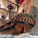
As some food for thought I have a picture showing our hero's left side. It doesn't look bad and with all the rigging also being prominent in view, I think you need not to base your decision about which variant to build on that view of the figurehead alone. And resting places may change...
-
Beef Wellington reacted to Ian B in HMS Bellerophon by flyer - FINISHED - Amati/Victory Models - scale 1:72
After lots of agonising I started with a couple of furled sails..I will do a mix of full and furled.. so thanks for your great dry runs with the paper..super idea
-
Beef Wellington reacted to Blue Ensign in 36 Foot Admirals Barge by Blue Ensign – FINISHED - Vanguard Models – 1:64 scale
Post Eight
I took the obvious and simple approach.
9397
The bulkhead was faced up with a piece of 0.6mm Pearwood sheet.
9404
A new platform was cut out of the same stuff.
9405
The plank lines were lightly scribed into the surface.
9410
Wash boards will be fitted around the edge.
9412
I still can’t help feeling that the fore platform should sit below the gunwale level.
Every contemporary model I have seen shows this, as indeed does the Vanguard Pinnace kit in the same series.
I did wonder if I had somehow made a mistake in the build, but the kit photo’s show pretty much the same result.
I can’t contemplate chopping out the bow bulkheads to lower the platform, I fear it would put too much strain on the delicate construction, so we are where we are.
9414(2)
The final option is to add wash boards which go some-way to redress the balance and give a more authentic look, but it is a compromise.
9415(2)
I happened to have some spare wash boards from the Yawl kit.
9429
The detail devil in me can’t help noticing one other anomaly.
The first thole pins are shown adjacent to the fore platform, at the same level.
It was not uncommon for the first rower to sit on the platform but with the kit configuration the rower would be above the tholes which makes no sense.
This is an attractive model, and perhaps many will care little about the details I have highlighted. Some may say at 1:64 scale it is sufficient for the purpose.
I would, however, urge Chris to re-visit this kit, re-design the first two bulkheads to lower the platform to the same level as the thwarts (as per the Pinnace kit) and reconfigure the oarlocks to single banked rowing on each thwart.
‘nuff said, on with the build.
B.E.
18/11/2022
-
Beef Wellington reacted to dunnock in HMS Diana by dunnock - FINISHED - Caldercraft - 1:64
Thanks to all for the likes.
Continuing with catharpins, futtock shrouds and shroud cleats.
I made the first catharpin for the main mast, checked it for length on the model and thought I would make a simple jig using two pins in a piece of wood so that they would all be the same length. However when it came to fitting the other three to the futtock stave, I realised that my cunning plan didn’t allow for the increasing distance moving aft between port and starboard shrouds.
Luckily, I hadn’t cut the tailings off, so I could just cut one of the siezings from each catharpin and size them independently on the model. To make sure there was no mix up, I numbered each one before This process was repeated for fore and mizzen masts.
I hoped that once the futtock shrouds were fitted any slight slackness would disappear.
I wasn’t keen on Caldercraft’s instructions for making the futtock shrouds, using rope for deadeye stops and then leading it down to tie off at the stave. I had some 3mm strops left over from Swan so used these. The shrouds were made from 0.75mm stained rope. This is a little on the heavy side but still looks good to my eye. A hook was seized into the upper end of the shroud, clipped into the eye of the strop and led down to the futtock stave. The shroud is wrapped around the stave and then tied to the lower shroud with three siezings.
The mizzen futtock shrouds were set up in the same way but using 0.5mm stained rope.
The ratlines should be added next, but I will leave that until the topmast shrouds are set up so that any variations in their tension do not distort the ratlines.
The shroud cleats were tied on by first clove-hitching a length of thread onto each end and fixing with a dab of dilute pva.
Each cleat was then tied on to the shroud with overhand knots and another dab of pva. Making sure that the clove hitch is centralised helps with positioning the cleat on the shroud. Based on the belaying plan in the AotS, cleats are tied to every shroud on the foremast and the last two shrouds on the mizzen.
I'm working on the lower stays and collars now
Thanks for looking in
David
-
Beef Wellington reacted to Blue Ensign in 36 Foot Admirals Barge by Blue Ensign – FINISHED - Vanguard Models – 1:64 scale
Post Seven
The gratings are secured in place using tiny spots of ca but I have found with my previous small boat builds that small enough not to spread thro’ the gratings with an annoying shiny reflection, is not always sufficient to hold securely, we shall see.
9395
I took the precaution of cutting a pattern to fit over the gratings to protect the surface during the extensive messing around inside the boat to come.
9394
The ribs are easily fitted given the notches in the grating pattern, and they do stiffen up the hull.
9393
There is an adequate supply of strip for this purpose.
There are one or two little bits to fit as per sections 32- 35 of the blurb, but back in section 13 there is a part B25 indicated, which as far as I can see is not mentioned again.
9389(2)
I suspect it may have something to do with the Foredeck but If it is, I think the instructions need re-visiting to be more specific in this area.
9388(2)
It’s not an easy match in any case, and the foredeck fitting has issues. If the notched back edge is intended to slot into the second bulkhead, then the first bulkhead should sit below the gunwale.
9292(2)
The first bulkhead and bow pieces are level with the gunwale.
(The bow stem extension has broken off, but that is easily fixed.)
9393(2)
This bulkhead, from the photos appears to form the vertical face of the fore platform.
9390
This rather unflattering macro of the bow end demonstrates the issues.
(Part of the Pearwood bulkhead on the port side snapped off during trimming.)
The problem is how to model the fore platform.
To use part B25, the first bulkhead would need to be rebated to accept the part, not an easy task at this point.
My thoughts are that the second bulkhead be infilled and brought level with the first bulkhead, and a piece fashioned to fit.
If this stands a tad proud of the top line planking, it can be used to support a bow wash strake.
I need to ponder this awhile, but until it’s sorted, I can’t really move forward with this build.
B.E.
17/11/2022
-
Beef Wellington reacted to mtaylor in HMS Sphinx 1775 by mtaylor - FINISHED - Vanguard Models - 1:64
Thanks for the advice and comments everyone. To carry one with Sphinx, I am working a bit outside the instructions at this point and sorting processes and methods out. Hopefully, I'll have it completed by the end of the year as long as nothing else gets in the way. I'll update once I have some real progress.
-
Beef Wellington reacted to BANYAN in HMCSS Victoria 1855 by BANYAN - 1:72
Thanks John.
Hi Keith, the whole is made from wood. The hull was carved from a block then hollowed out to shape; then the lining simulating cork covered with canvas) added. I have still to add duckboards, lifting gear etc. We have omitted the tholes at the moment as they are so small art this scale - but I am tempted to do this when I add the pre-painted (vermillion) rubbing strakes and boat badges in the bow.
I have yet to come to grips whether hanging loops would have been included with the rubbing strakes, for men to hang onto or assist their scrambling into the boat. The UK Life Saving boats were starting to show them, but not evident in the NMM model.
cheers
Pat
-
 Beef Wellington got a reaction from Blue Ensign in 36 Foot Admirals Barge by Blue Ensign – FINISHED - Vanguard Models – 1:64 scale
Just found you again BE, thankfully before you're finished. The small boats are fascinating and this is definitely one that has tempted me. I'm amazed that the flying transom only became detatched once, and have no doubt that the silk purse is not far away...definitely agree on the replacement of the transom panel.
-
Beef Wellington reacted to Steve Anderson in HMS Victory c.1765-1791 by Steve Anderson - FINISHED - 1:64 scale
Part 6 The Figurehead.
Pictures say more than words on this phase of "Victory". The material I used to carve this is called prototyping foam, also known as butterboard. It is a urethane fine cell structure that can be carved, milled, and sanded. It's available through McMaster-Carr. The huge advantage is there is no grain to contend with. That said, lets get down to the carving and painting of Victory's original figurehead.
For the tools I used a Dremel with a small ball cutter for removing large areas of material. Since I'm an Engraver I modified a few cutters into miniature chisels. Finally riffler files to smooth things out.
Side note: I repositioned what I call the "Rose Parade" waving of arms and hands.
From NMM the 1/2 scale sculpture of the figurehead which I scaled to 1:64.
Next Part 7 The stern galleries and start of the upper deck long 12 pounders.
-
Beef Wellington reacted to catopower in HMS Wolf 1754, 10-gun Brig (Snow) - Shipyard - 1/72 - CARD
Shipyard is a line of paper/card models from Poland, where paper models seem to be so prevalent. Shipyard includes kits of sailing ships, world lighthouses, dockyard structures, and more. But, this review is a look at one of their higher end products – one of their kits which, rather than featuring printed paper parts that must be cut out from their sheet, instead provides laser-cut parts that must be cut loose from their sheets and painted.
The range includes the small schooner Berbice, the Santa Maria, the cutter HMS Alert, all the way up in size to the 28-gun frigate HMS Mercury. The HMS Wolf kit, released around 2015, is about as close as one can get in size and complexity to the HMS Mercury kit, though their kit of the Dutch pinnace Papegojan is probably just about as detailed and complex.
All of Shipyard's laser-cut card kits are made in 1/72 scale. They all come in large, flat boxes that contain all the laser-cut components, plus color printed instructions, some plan sheets that are mostly for the rigging, laser-cut and etched sails, color printed flag sheets, wooden dowels for masts and yards, laser-cut blocks and deadeyes kits, white linen rigging cord, turned brass cannon and swivel gun barrels, cast resin decorative pieces, several jars of acrylic paint, a couple nice paint brushes, and more.
Everything comes pretty neatly packed with various components stored in separate cardboard boxes, which helps protect all the parts during shipping.
The instruction book is 32-pages in full color, including the cover, and is mostly photos at each stage, with the significant parts labeled by their part numbers. There is some text, but not much. What there is is in Polish, with German and English translations also given.
The Instruction Booklet
The one thing that is not included that I think would be really helpful, is a parts list that shows the numbers, where in the instructions the part is called for, and on what sheet to find the part. I'll come back to this later.
The Plan Sheets
Masting and rigging is detailed in the separate plans sheets. There is no one overall profile plan sheet, these are all just detail sheets. But, if you look closely, you'll notice that some assemblies, like the gun carriage are more fully detailed in the plans sheets. Also, the metal parts that you need to make, like hooks and eyebolts and such, are identified on one of these sheets, not in the instruction booklet. So, it's a very good idea to study these sheets to see what's described on them.
The kit contains no eyebolts, split rings, hooks or things of that nature. Instead, a couple sizes of copper wire are provided, and the plan sheet below identifies the small metal parts you must make in various sizes. These are all identified in the plans with the letter 'Z' as a prefix. The instruction manual will call for these parts, and you will find no part with this number. Again, that's because you have to make all the Z parts yourself from wire.
If you prefer to make your own sails out of, say, paper, some nicely detailed patterns are provided, showing locations of reinforcements, cringles, reef bands, etc.
The Parts
As you can see here, there are a lot of parts sheets, and on each of those there are a lot of parts. There's a LOT of detail here, and just seeing how much detail there is in the kit makes the kit really exciting to work on.
By the way, my apologies – these photos are on the blue background of my cutting mat and the photos were taken with an iPhone, which does it's own automatic color balance, so all the sheets look kind of yellowish here, which they are not.
The only color printed parts in this kit include the flags sheet, which is printed double-sided, and the decorative friezes. I don't know if this was intentional, but my kit included two copies of this sheet.
Apologies too for the bad focus on this photo – I don't know what happened here. In a sharper world, you'd see all the bulkhead parts and hull stiffeners. Those who've built Shipyard's paper models probably know already about how well these laser-cut parts fit together, and form a very stable hull structure.
This odd, brownish looking sheet is actually dead black. But, at least here you can see that the part numbers are there. When I looked at this sheet, I had to hold it at an angle, under a bright light in order to see the number or to even identify the part.
There is one small sheet of clear acetate for the windows and the stern lantern.
Note that the deck planking is engraved onto the card pieces, with nicely located butt joints, nibbed plank ends, proper scarf joints, and treenails.
Lots of parts make for lots of details and lots of work. But there's no shaping, drilling, milling, filing, sanding, carving, required. it's all mostly cutting, gluing, and painting.
Sorry, I didn't take pics of the cannon barrels, resin "carvings", brushes, rigging line, or the paint jars. But, I will mention that earlier kits of this line had jars of paint that could easily dry up. I'd mentioned this problem to Shipyard years ago. They have since gotten jars with rubber grommets in the lids to create a better seal, and this seems to have alleviated the problem.
Speaking of paints, those included in the kit are apparently some decent quality artist's acrylics. They go on dead flat and have some transparency to them, so you should be able to see some of the laser-etched details through the paint. The paint is a Polish brand called Renesans. I like them, but they hard to find, except on some European online art supply stores.
Summing it Up
This is a pretty well detailed looking kit. It, and the entire line of Shipyard laser-cut kits, are very different from most paper model kits, given that nearly every paper model kit is mostly paper that has to be cut, rolled, folded, or curved, and may have a laser-cut skeleton for strength. This kit is entirely laser-cut, but includes parts using other materials for best appearance or easiest construction.
The heavy use of laser cutting comes at a cost, and these laser cut kits are a lot more expensive than traditional paper models, and this kit is no exception. This kit has a cost that's somewhere in the neighborhood of $200, give or take, depending on where you purchase it. That's a lot more than a traditional paper kit, but not really much different from a comparable wooden kit, and there's a lot more to it than a box of wood with some laser-cut pieces.
The kit is available from a number of online shops, including Ages of Sail, where I got mine, Cornwall, Shipyard's online shop, and maybe someone will chime in about a Canadian shop.
Did I miss anything?
-
 Beef Wellington got a reaction from hollowneck in HMS Granado by HardeeHarHar - Caldercraft - 1:64 - Bomb Vessel
You have a very fine model coming together here Brian. Especially like your photos of the stern, the colour combination is very pleasing to my eye! Will be following along from here...
-
Beef Wellington reacted to Some Idea in How do you get a smooth finish?
Some great advice but there is no short cut to getting a super smooth finish. I built Billings Fairmount Alpine using epoxy as a sealer and I too used Halfords Matt primer to see the imperfections. Any imperfections were filled using a fine two pack polyester car filler. It just takes hours of patience which you obviously have.
The finish you have achieved is fantastic and a real credit to you.
Here’s my effort after probably the same hours that you put in. Looks about the same I would say
-
 Beef Wellington got a reaction from Wintergreen in 36 Foot Admirals Barge by Blue Ensign – FINISHED - Vanguard Models – 1:64 scale
Just found you again BE, thankfully before you're finished. The small boats are fascinating and this is definitely one that has tempted me. I'm amazed that the flying transom only became detatched once, and have no doubt that the silk purse is not far away...definitely agree on the replacement of the transom panel.
-
 Beef Wellington got a reaction from mtaylor in 36 Foot Admirals Barge by Blue Ensign – FINISHED - Vanguard Models – 1:64 scale
Just found you again BE, thankfully before you're finished. The small boats are fascinating and this is definitely one that has tempted me. I'm amazed that the flying transom only became detatched once, and have no doubt that the silk purse is not far away...definitely agree on the replacement of the transom panel.
-
 Beef Wellington got a reaction from Canute in How do you get a smooth finish?
Looks great. Was the primer that you used matte? That would make seeing any imperfections that mush harder, as it looks like the finish has a satin finish which would show these much more.
-
 Beef Wellington got a reaction from Peanut6 in HMS Granado by HardeeHarHar - Caldercraft - 1:64 - Bomb Vessel
You have a very fine model coming together here Brian. Especially like your photos of the stern, the colour combination is very pleasing to my eye! Will be following along from here...
-

 Beef Wellington got a reaction from Knocklouder in HMS Jason by Beef Wellington - Caldercraft - 1:64 - Artois-class frigate modified from HMS Diana 1794
Hancing pieces and volutes....
I'm a little embarrassed that it has been so long that I've been away, somewhat from the shipyard but also this wonderful site. With the weather starting to turn and a bit more available time it seemed a good time to get back into things and try to pick up from a point that I left a little disheartened so many months ago. To be able to move forward, I had to come up with a solution for the hancing pieces which should then really allow much of the final hull form to be finalised. The problem I faced stemmed from the fact that I had to come up with a hancing piece volute 6mm high (per NMM plans) to transition the upper rails into the waist, and following a profile already established for the other rails. Although these are not large details, they are features that to my eye need to be sufficiently elegant and accurate to avoid detracting from the lines of the hull. I tried many different approaches, but here is the one that worked best for me and provided a method of construction that allowed consistent results. I'll apologize in advance for quality of the photographs, I was so focused on the work and forgot to check the photo quality as I progressed.
2.2 mm holes were drilled using a pin vise into some 2mm pear wood (actually 1.5mm + 0.5mm pear laminated together cross grain because I didn't have any 2mm sheet stock), this matches the starting thickness used for the upper rails which started as 2x2mm square strip. (A 2.2mm hole was found through visual trial and error to introduce the gradual narrowing of the rail into the end of the volute). A 1.5mm diameter recess was then carefully made at the edge using a round needle file at 45deg to the bottom of the hole. Each 'blank' was then cut from the sheet, given a slight reduced profile using an exacto blade, and a thin cut made above the filed lobe (explanation below).
Small sections of 1.5mm diameter pear dowel were then glued into the 1.5mm recess, so they very slightly protruded above the top of the block. Sufficient PVA glue was used to ensure that these were well bonded. Once dry, a the top of the blanks were gently cut back and carefully finished against a circular sander so that the top edge of the blank was tangential to the top of the 2.2mm drilled hole (the cut previously made above the recess allows this section to release easily as it will no longer be needed.
A length of 2x2mm pear wood strip was scraped with the same molding profile as used previously in the build, but care taken to leave an untouched section toward the end. The volute blanks were then attached to the unfinished end of the scraped molding. PVA glue was used generously, and left to dry overnight to ensure a full strength bond. Once dry, the excess was then carefully cut away to give proportions pleasing to the eye (mine at least) and ensure that the final volute form would be 6mm high. The rough cut was then very carefully reduced to its final shape using various grades of sanding sticks.
Once the final shape was achieved, a profile needed to be introduced to match, and transition as smoothly as possible from the molding strip into the curve of the volute. To do this I needed to create a second scraper profile at the very edge of a razor blade to work on the volute curve effectively (the scraper profile used previously for strip had been centered to give best control on straight strip). This was performed very slowly as catastrophic failure would be very easy! While it is true that it took multiple experiments to get this method down, it did work well and the four needed volutes were all first time efforts with no rework, and despite the many imperfections highlighted by the macro lens, the results to the naked eye exceeded my expectations.
In position, the volutes will now allow final shaping of the hull profile. Onto the next challenges!
-
 Beef Wellington got a reaction from AJohnson in HMS Granado by HardeeHarHar - Caldercraft - 1:64 - Bomb Vessel
You have a very fine model coming together here Brian. Especially like your photos of the stern, the colour combination is very pleasing to my eye! Will be following along from here...
-

 Beef Wellington got a reaction from HardeeHarHar in HMS Granado by HardeeHarHar - Caldercraft - 1:64 - Bomb Vessel
You have a very fine model coming together here Brian. Especially like your photos of the stern, the colour combination is very pleasing to my eye! Will be following along from here...