Maury S
-
Posts
1,490 -
Joined
-
Last visited
Content Type
Profiles
Forums
Gallery
Events
Everything posted by Maury S
-
 Nicely done. Maury
 -
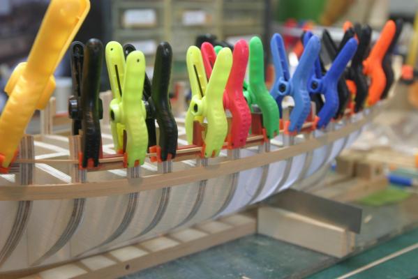
I started the planking above the wales. Tick strips were used to get the width of the planks...both sides line up. The first section of the strake fit well with a little heat from the bending iron. The longer next section will be trickier with the bend over the longer run. If I can't get a good fit, I'll spile the plank. The shadow between the plank and wale is much more pronounced in the photo. Some sanding will smooth it out a lot and the second layer of the wale will also hide it. Maury

-
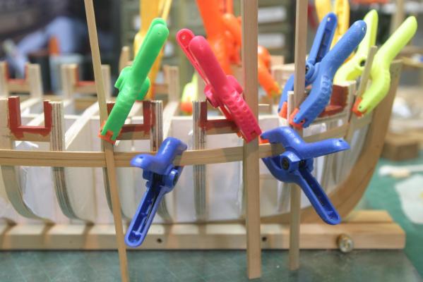
Molding was put on with 1/64" reveal and when the clamps came off, there were a lot of "bumps". A fair run is more important to me than a perfect 1/64" reveal, so back to the isopropyl for some adjustments. The port side looks good, but there is still a bump on the starboard. To make the molding fair at the forward gun ports, I set one end, then laid another strip of 1/16" across the top to make sure they aligned well. That came off since it was not glued. Maury

-
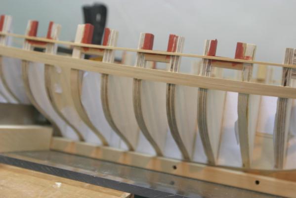
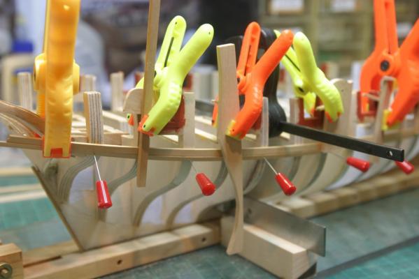
Wales going on. After the first one on the other side went on, I noticed it had slipped up during clamping and had to go to work with isoproply and undo about 10 spots to re-position it. All is well now. After the first strake was set and glue dried, the second went on. No further need for the batten so it came off. I did not bother to bevel the edges since they will be covered up with the second set of wales. I will smooth out the surfaces and run a sanding stick over the top and bottom edges for a smooth transition to the planking above and below. Maury

-
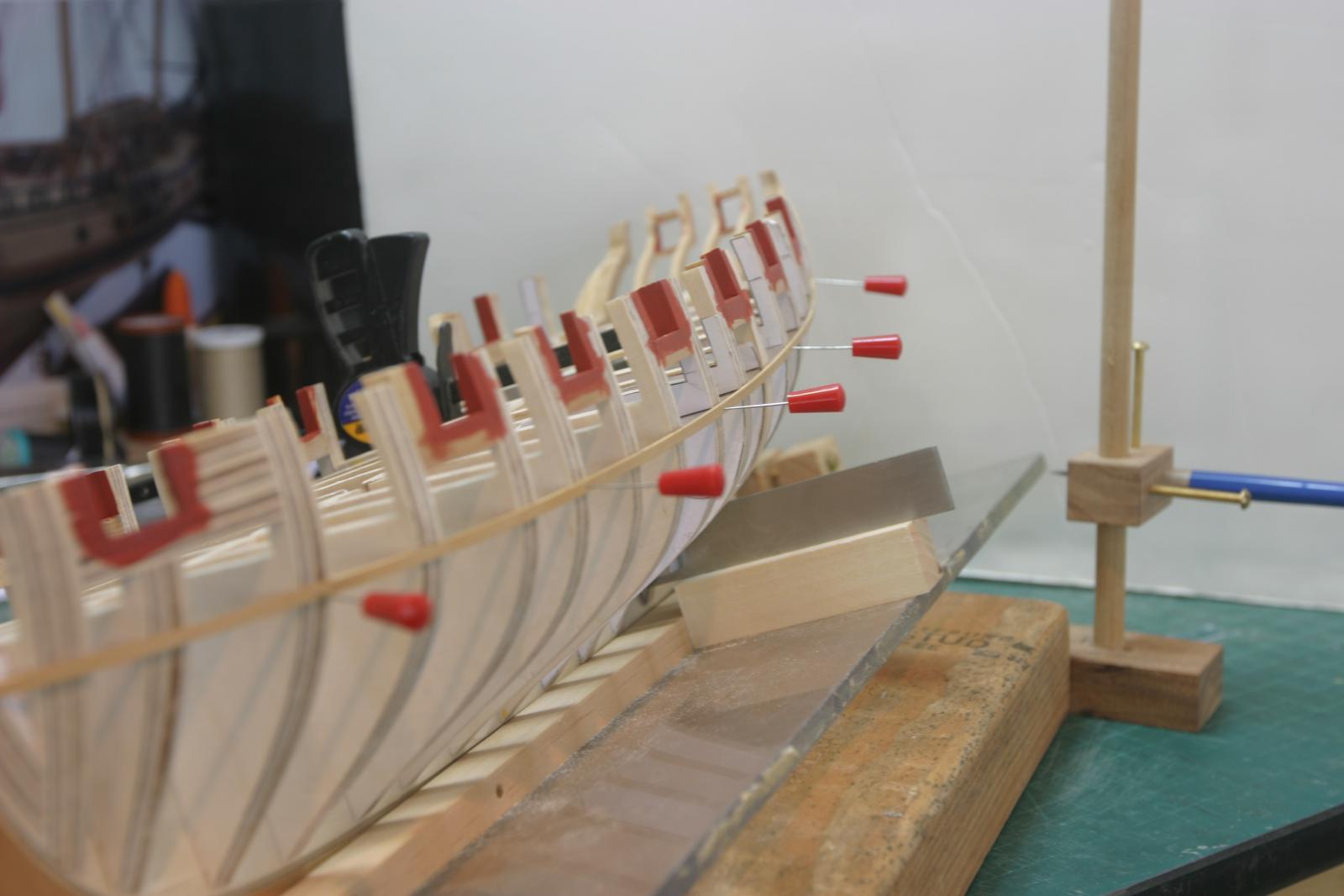
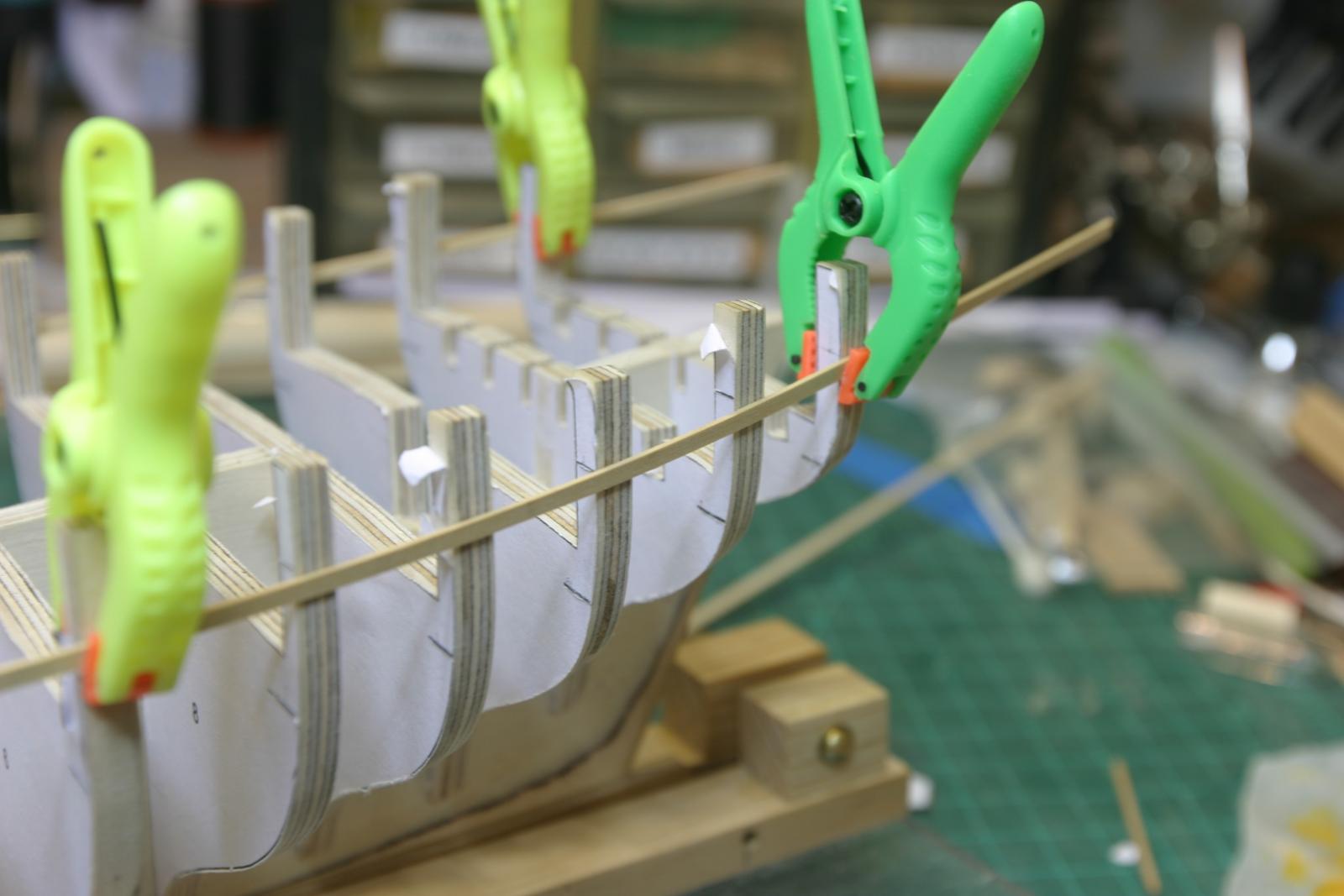
Inside of the gunports were painted (conditioner and three thinned color coats). I mixed a more "Copper-bottom" red than the one Chuck used...just personal preference on the color. A batten was installed using the lower reference marks, adjusted to a nice smooth run and pinned in place. I marked the height from the base board at several bulkheads and the stem and stern and repeated it on the other side. Even run from all angles. The bow-on shot looks like they may be a bit off, but the camera is tilted a ever so slightly. Both measure the same. Maury
-
I used some 1/16" basswood to build up the stern frames so there is a 1/16" notch per Chuck's instruction. I dampened the short pieces and bent them with my bending iron, then glued them in place and after 24 hours, faired them. I'll spend some time tomorrow checking the fairing of the bulkheads from every angle. It seems painting the inside of the ports is next, then on to planking. Maury
-
Thanks Chuck. It was over sanding!! I intentionally sanded it down. Easy enough to build back up. I've done plenty of that. Maury
-
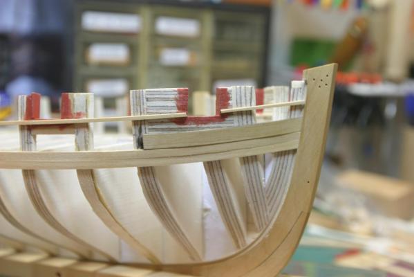
Sills and lintels are in and faired. Square tuck installed and fillers behind are faired. I'm not sure yet how the planking will lay at the intersection of the stern and square tuck. Some more fairing of the last bulkheads may be in order. Maury


-
Installing Sills and Lintels in the stern...The sills and lintels need a very slight bevel so I used my Miter-Sander with the 1 degree block. Flipped over for a parallel bevel on the other side. The starboard sill went in first, carefully measured position from the plan sheet (about 1'32" above the knuckle of the frame). I used a long beam set on a block well forward so the sill (fore and aft) would be roughly parallel with the deck and the port and starboard sills would be the same. Clamped and waiting to dry. Once both sills were in, I used a 25/64" block (the inside measurement of the ports) to set the height of the lintels. Maury
-
thanks Chuck, I see now that the inside is not planked. Maury
-
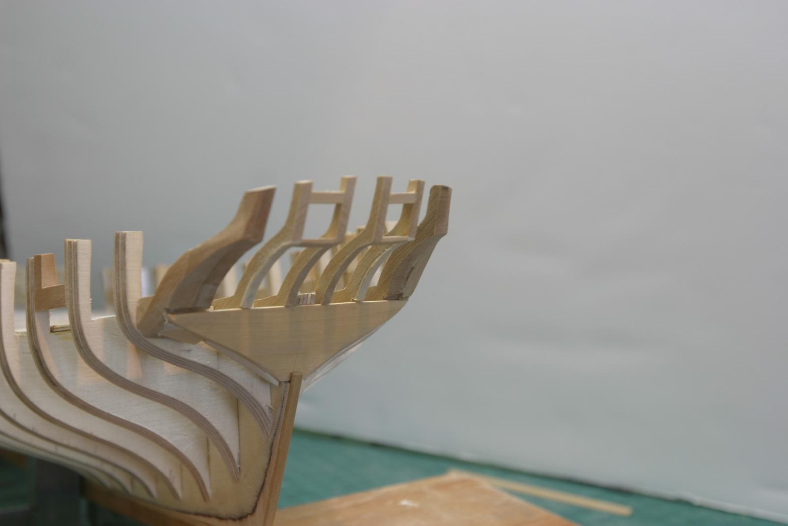
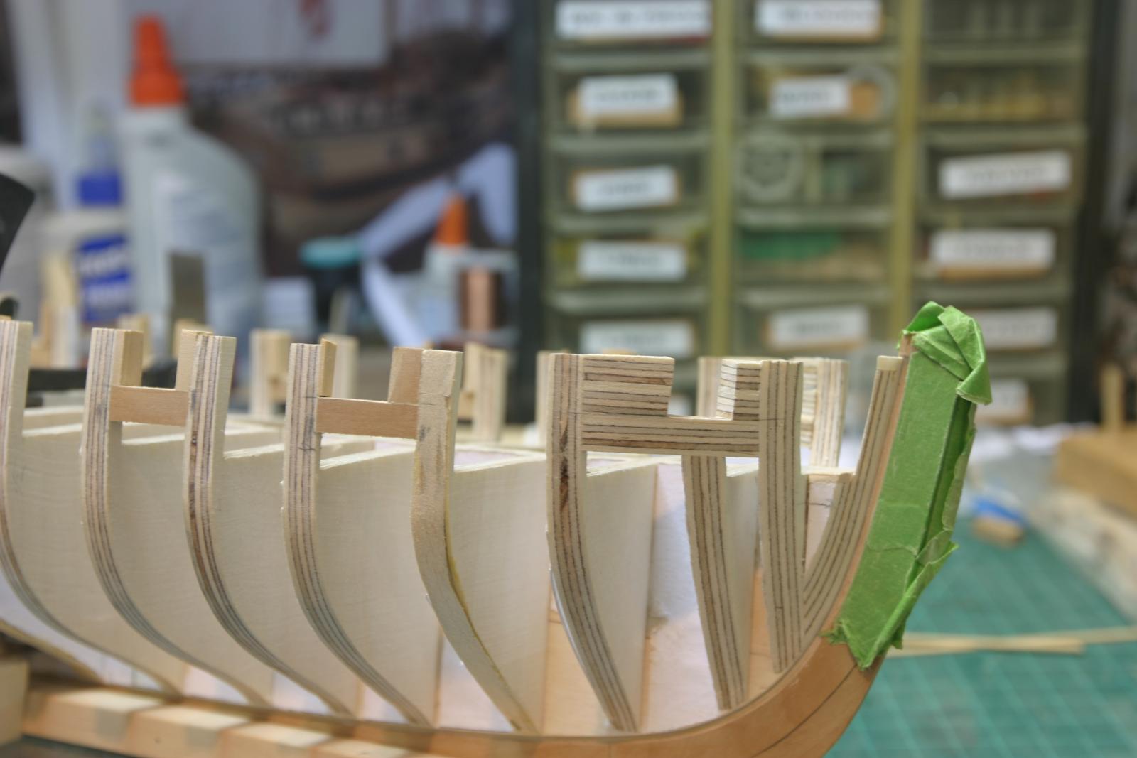
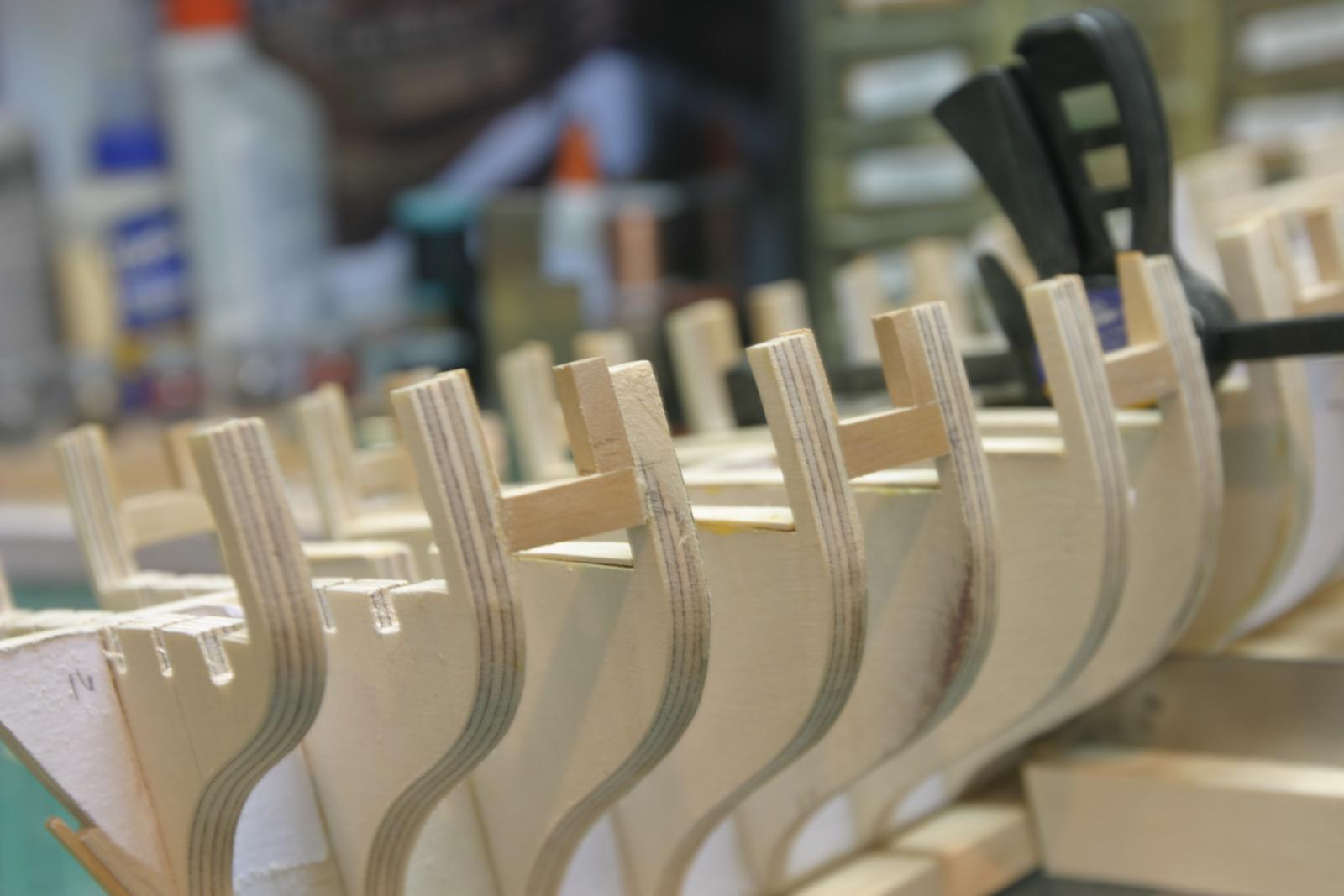
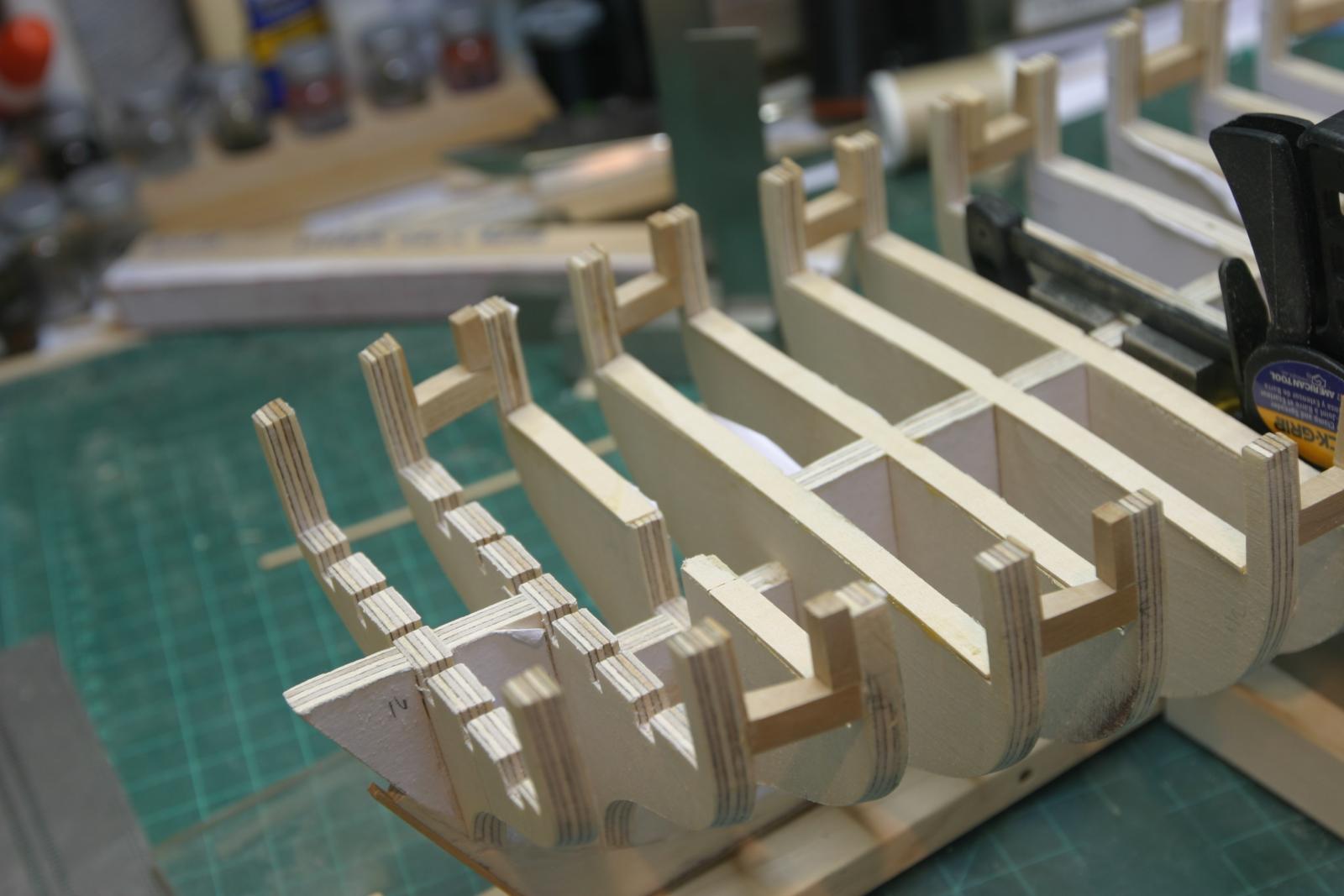
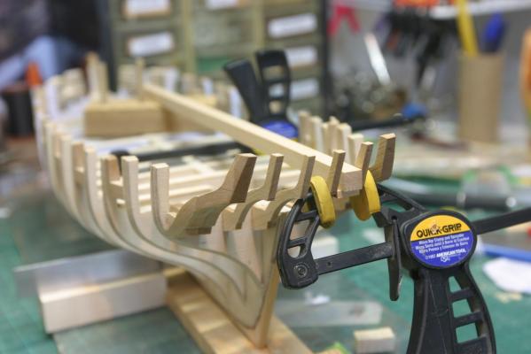
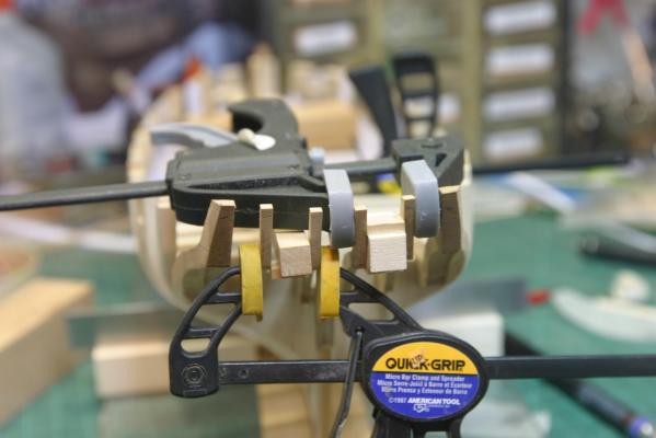
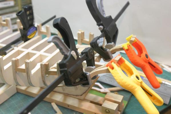
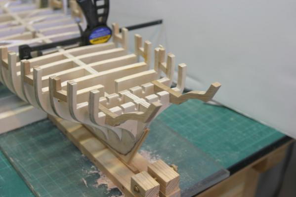
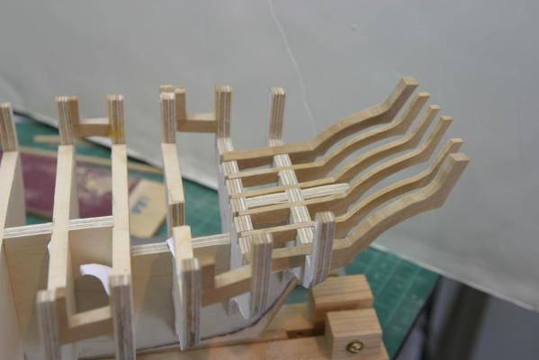
Stern frames going in. After sanding down the outer frames (ZZ) to be fair with the side frames, I started on the inner stern (X) frames. Knuckles at the correct height and the spacing between them being set by using a block between them to maintain the proper spacing. Next, the Y frames go in, with spacers for the width of the gun ports. The numbers on the blocks are 100ths of an inch in width. Next will be the sills for the gun ports. That will stabilize the X and Y frames. I don't see why I shouldn't put extra blocking between the X frames and Z and ZZ frames. It will just tie everything together better. When the clamp is removed and the blocks fall off, there is a nice bend to the stern. It will be nice when faired! Maury


-
Chuck, Re. the horse shoes, straps, etc. What is "Laser board"? Are you going to offer this as an extra? Rapidly approaching a "Kit". Maury
- 1,051 replies
-
- 1
-

-
- cheerful
- Syren Ship Model Company
- (and 1 more)
-
Chuck, I assume your horseshoes and butterfly pieces let-in to the keel. It looks great. Maury
- 1,051 replies
-
- 1
-
-
- cheerful
- Syren Ship Model Company
- (and 1 more)
-
Ed, She looks great. I'm surprised there is so little availible light in the cabin. No side port holes back there, so just a skylight? It's amazing the relatively small rudder size considering the rudders on today's boats. Not much considering the size of the ship. Maury
- 3,618 replies
-
- 2
-
-
- young america
- clipper
- (and 1 more)
-
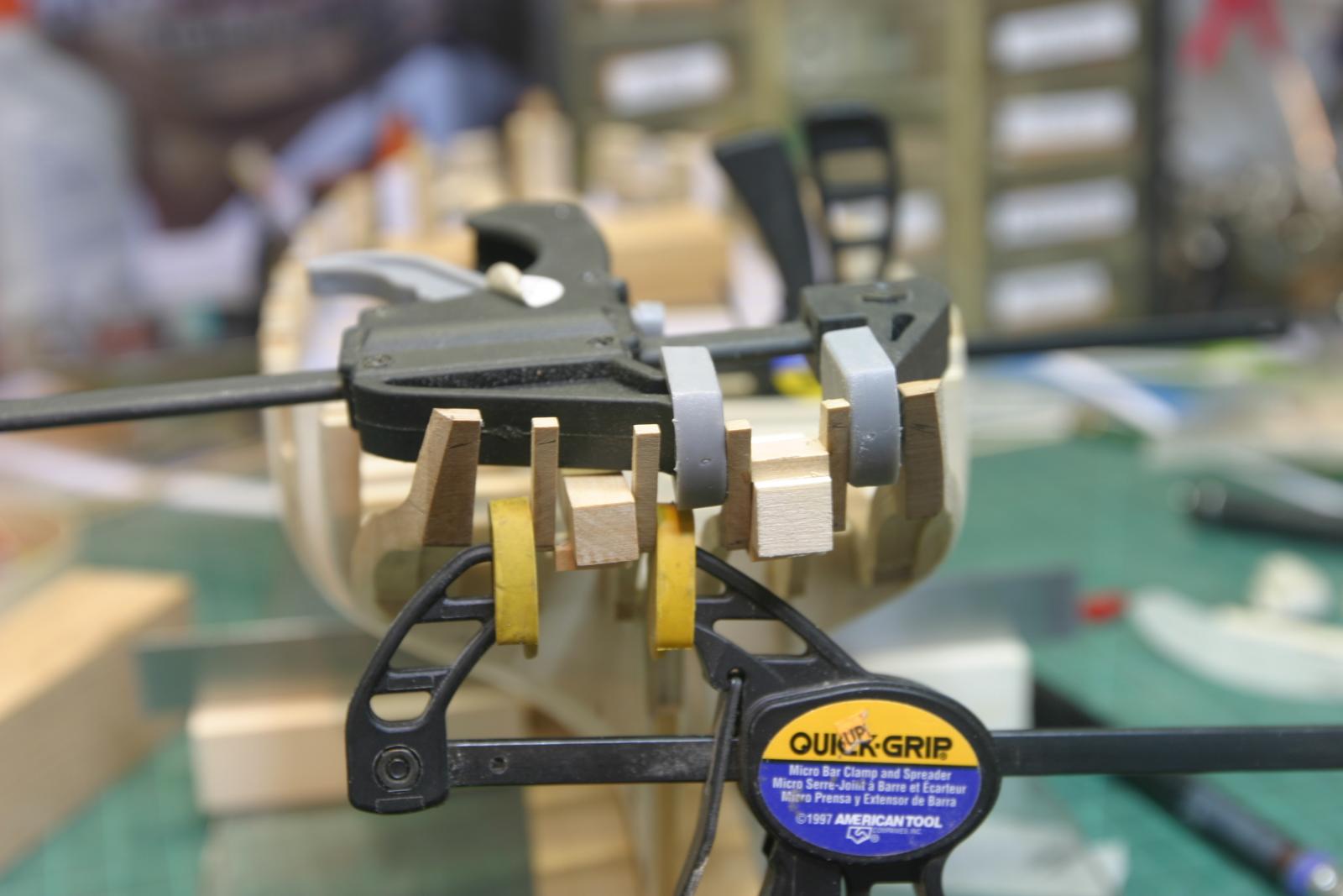
I used a steel rule to measure the height and tilt of the frames "Z". Held in place while the glue dried. Then the outer parts ("ZZ") were glued on. A large amout of these frames will be sanded down to get the right shape of the stern. There will likely be a lot of stress in the sanding so they will set for 24 hours before I go at them. Maury
-
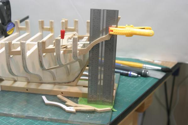
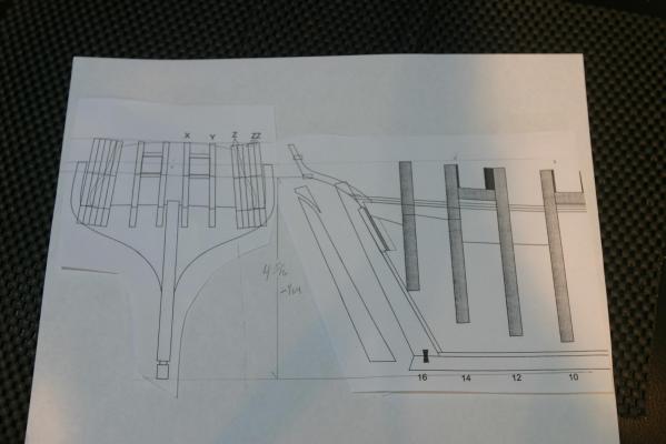
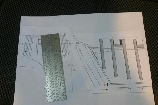
Measurements to determine the placement of the stern frames: The horizontal spacing is straight forward from the stern framing plan. Vertical spacing is a bit more of a challenge. The height above the building board to either the frame knuckles or top of stern frames are the obvious points of reference. Since the keel is curved I needed to find a line from the bottom of the keel (BOK) at the dead flat to the BOK from the stern frame. I cut out the stern frame plan and re-positioned it next to the end of the frame side elevation. See picture. By aligning it horizontally with the top of stern frames or top of bulkhead extension at BH #16 and taping in place, you will see the BOK is lower than the BOK at BH #16. I ran a line from the BOK at dead flat to BOK on the repositioned stern plan. At the aft end of the keel, the BOK is about 3/32" above the line just drawn. That's the amount of curve in the keel. I made a shim 3/32" and stuck it to the BOK at BH #16. With the skeleton back on the building board, and clamped down on the shim (and at dead flat) and plumb, I can accurately measure from the building board to the knuckles of the stern frames (about 4- 5/16"). To make sure the outer stern frames (Z) are tilting in per plan, I ran a line parallel to the inner-most frame to the line described above. See second picture. I measured from center line to the angled-line intersection and marked that on the building board. Holding my steel rule to the inside of the frame, touching the building board shows if any tilt adjustment needs to be made....or you can just eye-ball all of the above. It took more time to write this than do the measurements. Maury
-
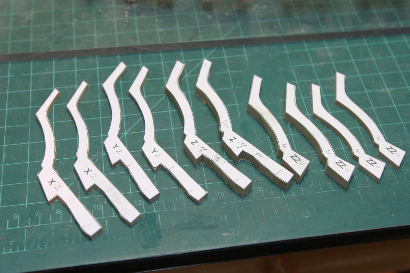
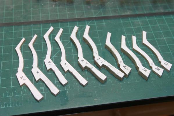
I cut the stern pieces on my scroll saw. The "Z" and two of the "ZZ" pieces were cut from 1/4" stock, the "X" & "Y" from 1/8". I cut and test fit all the pieces, not just "Z". They all inter-relate. Most of the notches in the bulkheads The angle of fitting is important for "Z". Any minor variation in the notches on the last two bulkheads makes a big difference in ultimate top of the stern frames. They are in roughly, but I need to make a bunch of measurements to confirm angles and heights. Maury
-
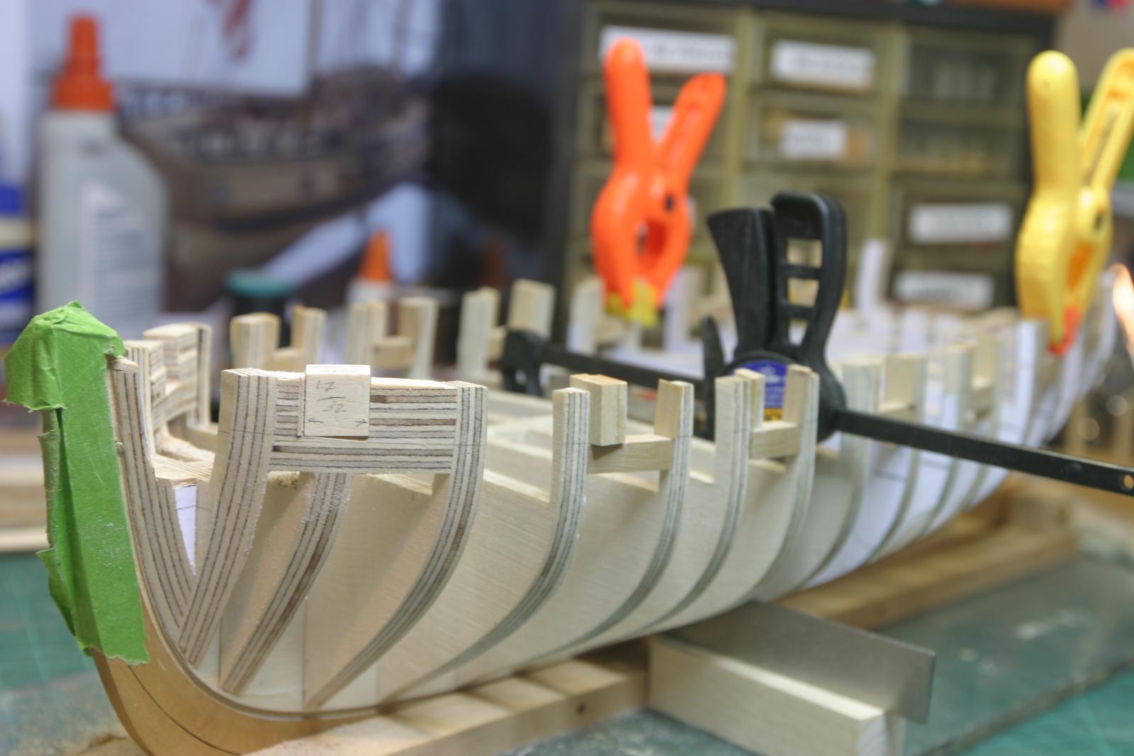
Sills fairing is done on the outside. One warning. I did not remove all the pattern paper from the face of the bulkheads before gluing in the sills. That creates a weak joint and a few failed under the stress of sanding. Make sure the pattern is removed before gluing. I started to fair the top of the bulkheads that create the deck beams. There were some low spots in the back, so I glued on some 1/32" basswood strips and then faired the deck before I add the stern pieces. Maury


-
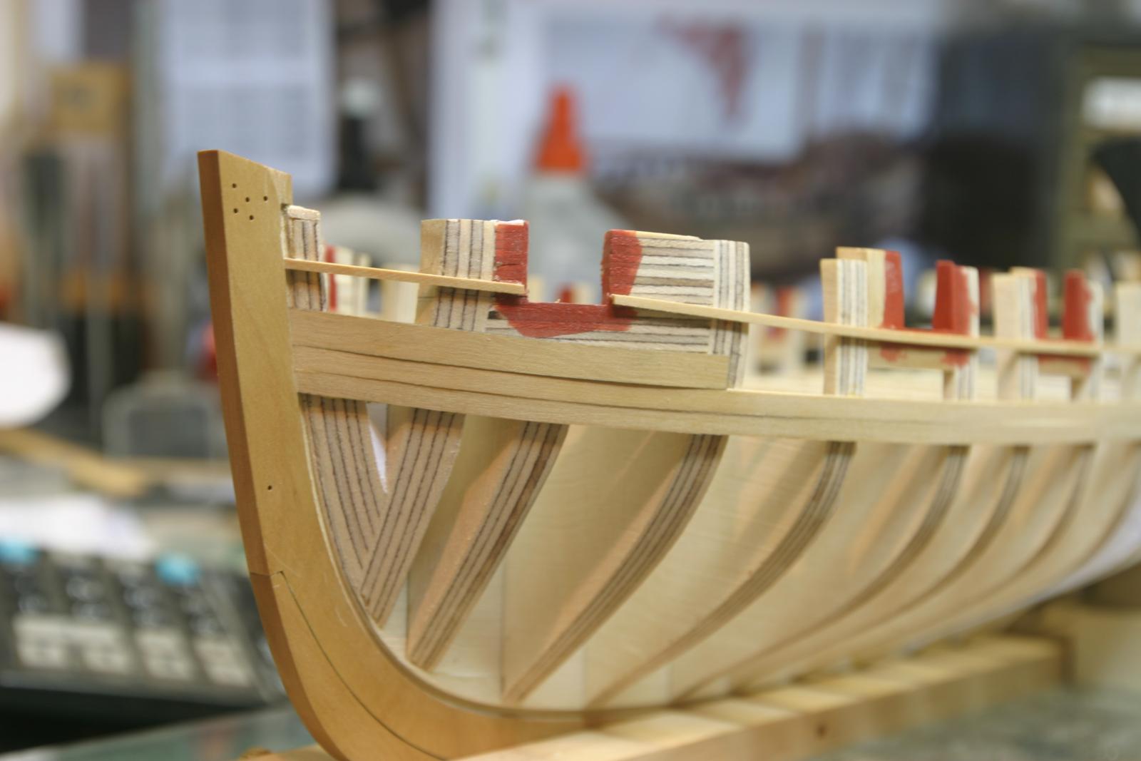
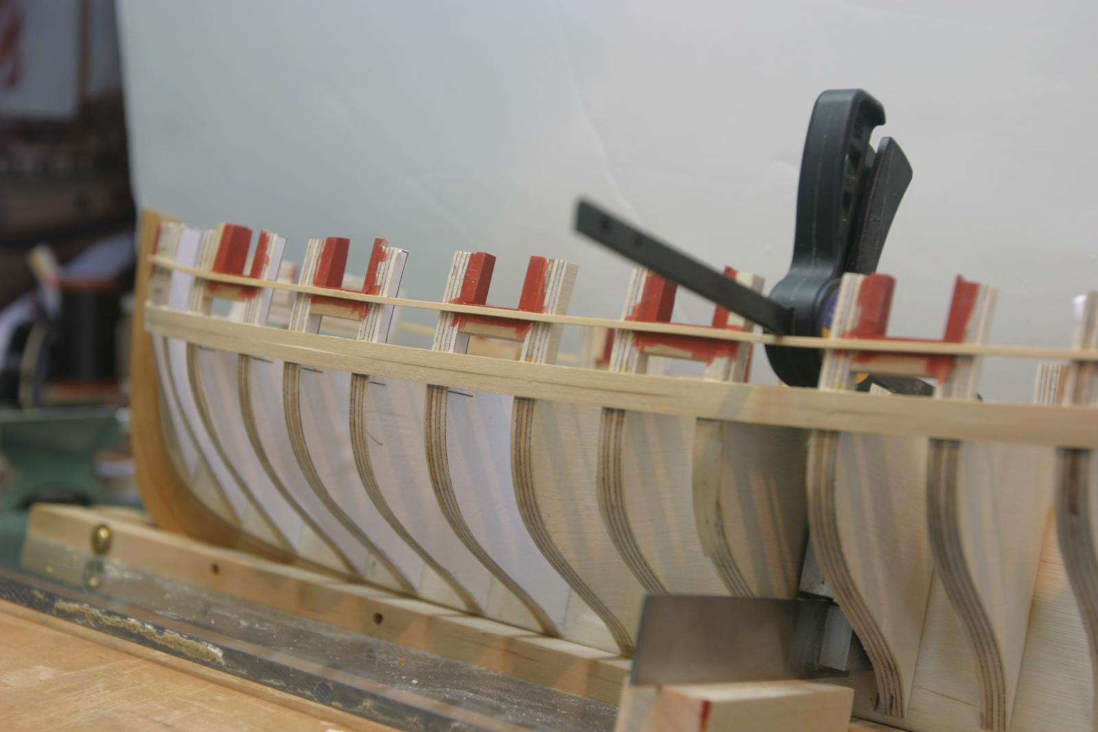
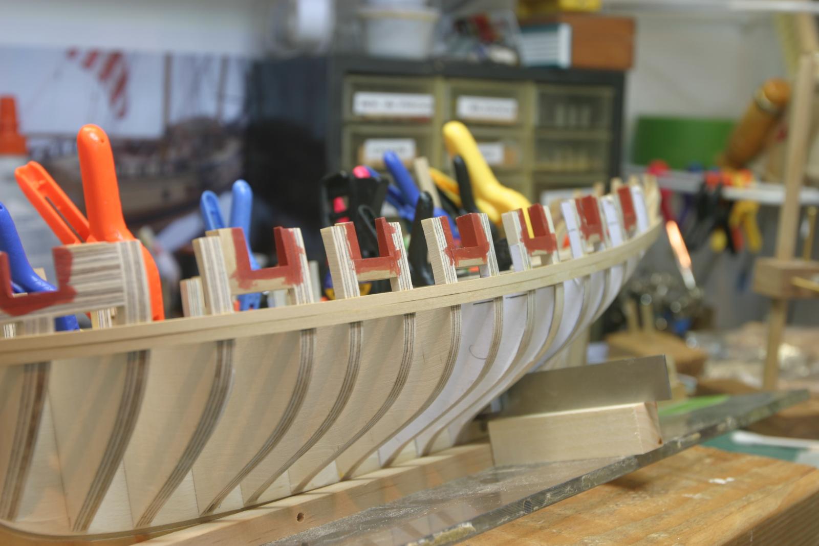
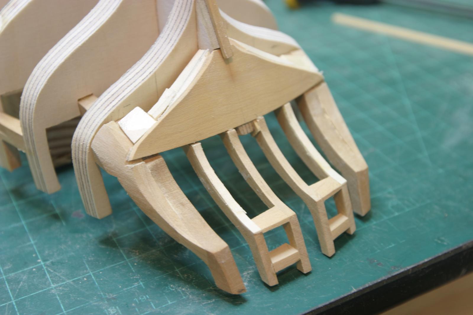
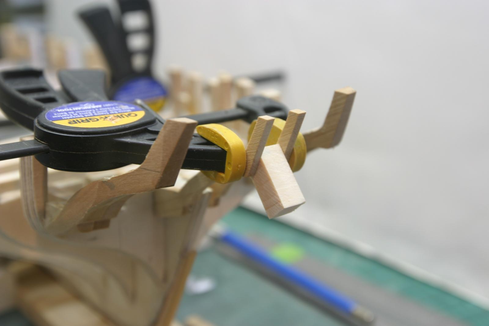
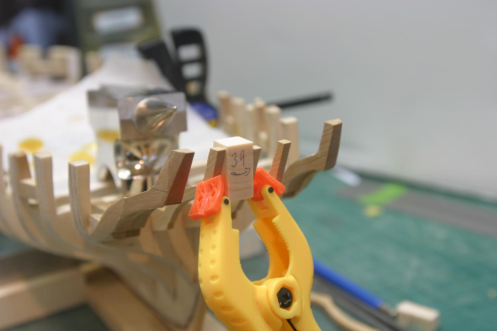
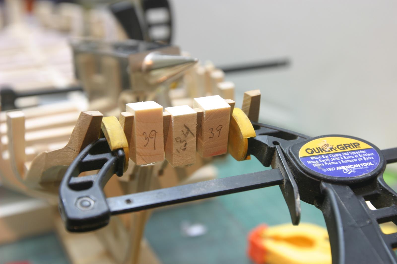
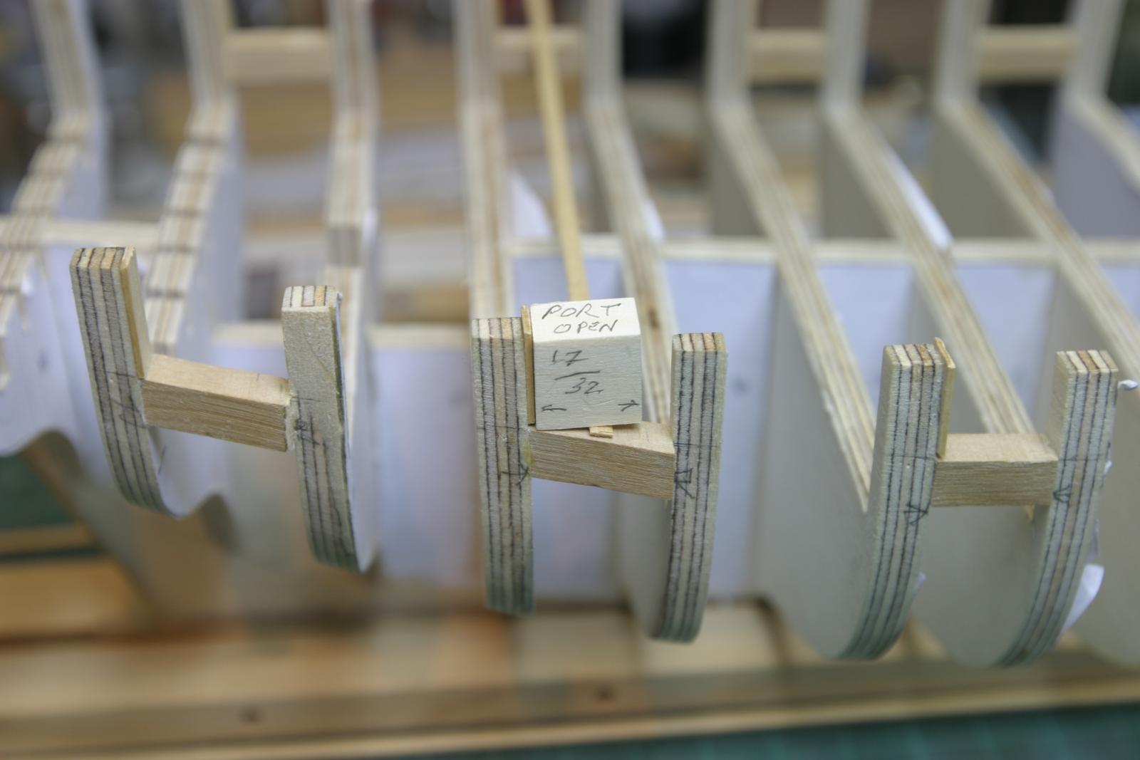
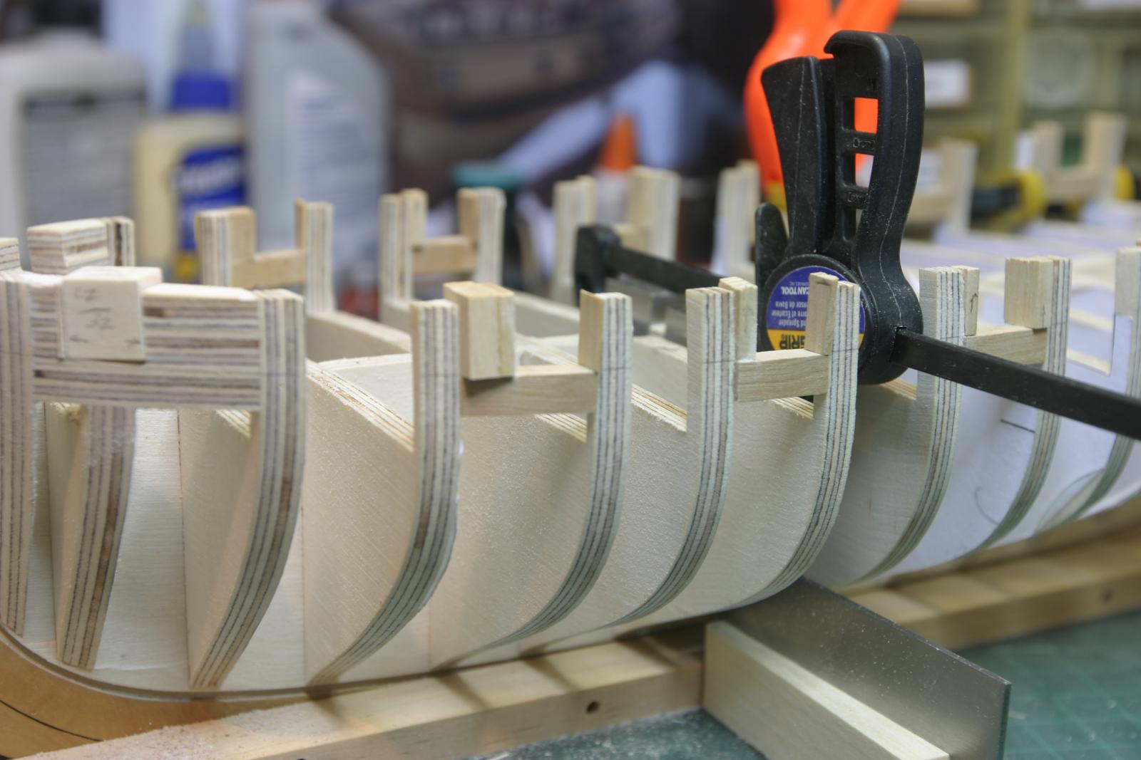
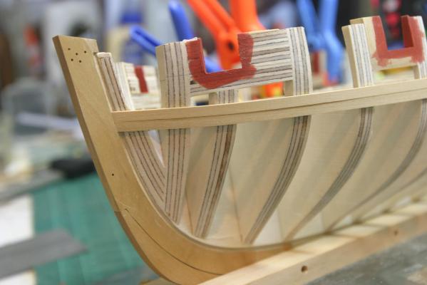
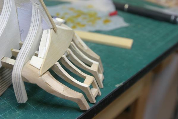
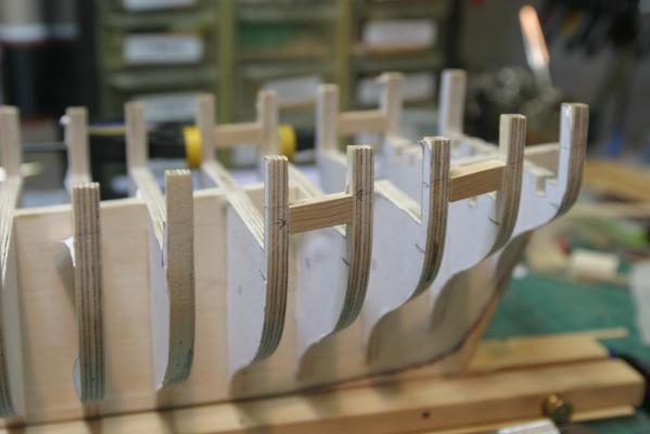
Ports roughed-in. I made a block 17/32" wide representing the size of the port openings. I put the thinner of each vertical in place on both port and starboard. Then I used the block at each port to determine the thickness of the remaining verticals. Any slight variations in size of verticals was made up in the thicker piece. Lots of bits and pieces from the scrap bin. Chase ports were cut with a razor saw and finished off with a coarse flat rifler file and then 150 grit sanding stick. They all need fairing now. Maury


-
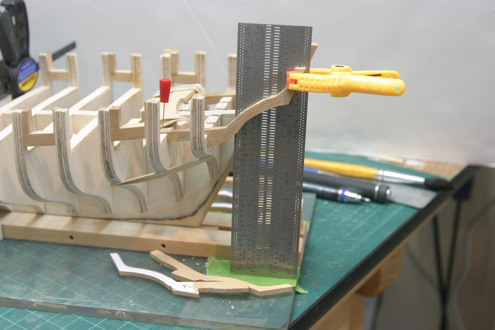
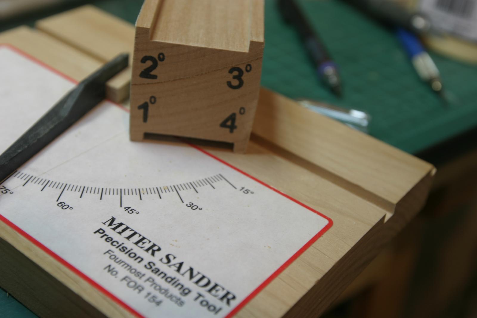
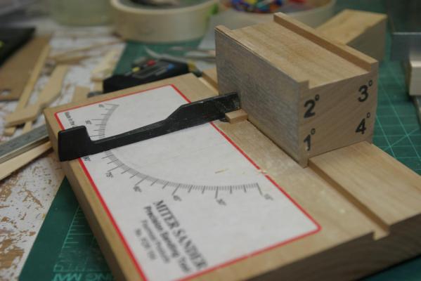
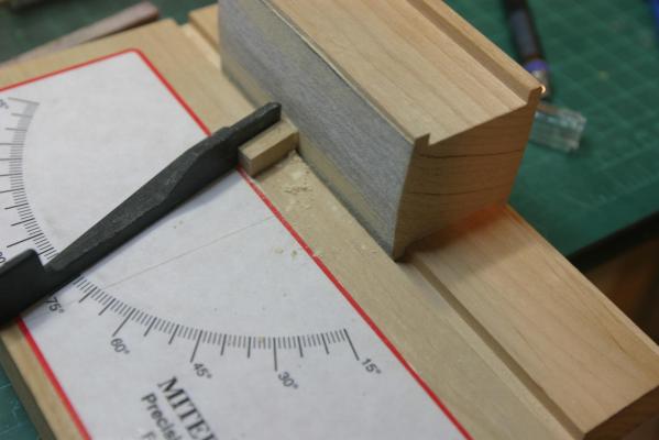
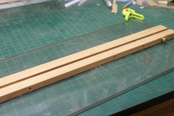
More work on the port sills. The sills require beveling in two dimensions. The ends have to be mitered (sides) so they fit between the bulkhead uppers, but they need an additional bevel in vertical plane where the sill rises following the shear. I use a Miter Sander. It comes with three sanding blocks with angles from 0 to 8 degrees. Here I'm putting a 4 degree bevel on one end of a sill. The other side gets a similar bevel on the opposite edge so they are parallel. They get inserted between the uppers following the new modified reference lines drawn on the bulkhead uppers. You can see the grain on the boxwood, which is a big disappointment with the quality of wood I got from Lumberyard. It won't matter in this spot, but where it's visible, I'm going to go to with Crown for my next buy. Maury

-
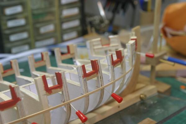
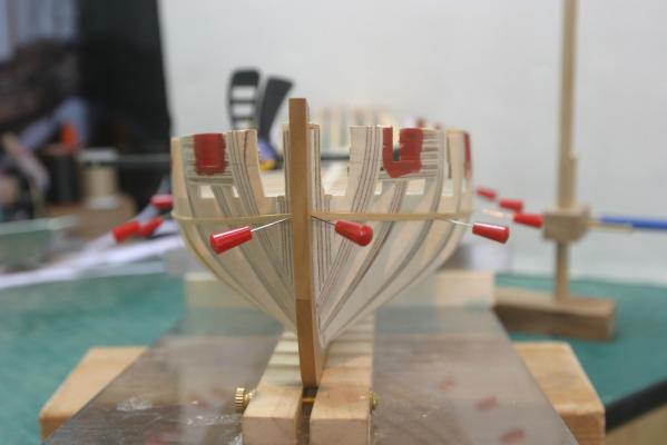
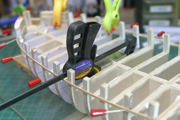
Continued work on the fair lines for the port sills. Today I had trouble attaching the photos in the order I wanted. (The second picture is the jig I use to hold her while I'm working.) One strip of wood is glued to the plexiglass base, the other is loose and connected with bolts to tighten the keel in the jig. Very basic. The first shot shows two machinist squares being used to make sure the spine is held plumb. Measurements from side to side are now possible. I checked the height from the base to the top of the battens at the back side of the fore bulkheads and the front side of the aft bulkheads and made sure the stbd. side matched the port side at every intersection. Once I was happy with the lay of the battens, a thin pencil line was run across each bulkhead at the top of the batten, creating "modified" upper reference lines. Maury
-
I was thining they should line up square to the outer planking like the ports in the front. It is sure easier to just leave the inner edges parallel to the bulkhead extensions. Once thinned down, it probably doesnt matter.
-
One more question. Should the port uprights be beveled so the openings are square with the outer planking rather than square to the keel? Maury
-
Plans question for Chuck: The bulkhead plan (use dead flat as example) upper reference line is 16/32" above the bottom of the floor (top of deck beam equivilent) at the sides. On the plan side view showing bulkheads and port sills, the top of sill (= upper reference line) is 12/32" above the bottom of the floor (top of deck beam) . Is the side view showing the floor (top of deck beam) at midships reflecting the round-up of the deck or at the side? Maury
-
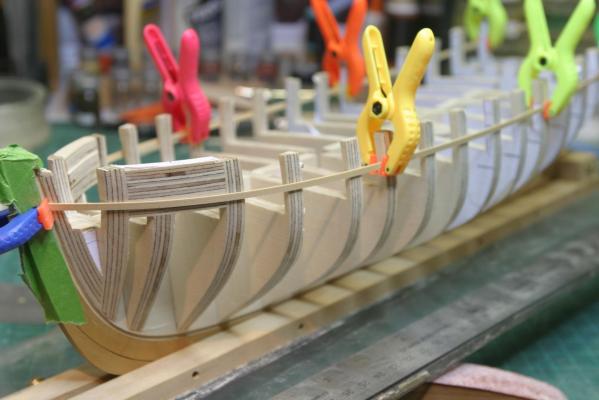
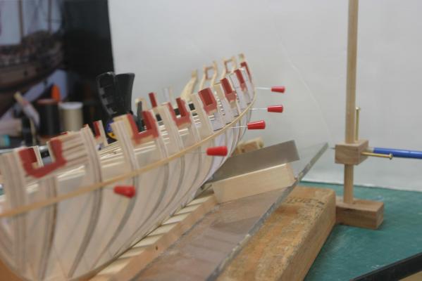
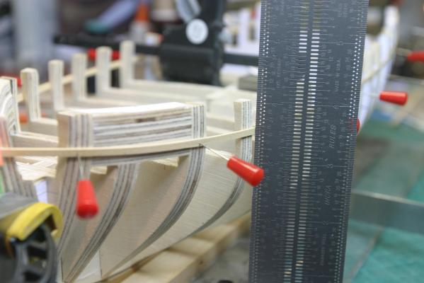
I've faired so that a batten lies flat across all bulkheads. Next is to set the tops of the port sills via the use of a batten that runs the entire length, top aligned with the upper reference lines. Chuck warns they will not all line up and need minor adjusting. I can get a fair run with some ref. lines above and some below the top of the batten. Now for some assistance. There is no upper reference line on the aft-most bulkhead, so I penciled one in at 24/32" above the lower one (approximate spacing of the preceding bulkheads). See second photo. At the end of the run of the batten, if I use the second from aft, the batten would be quite a bit higher. If I use the third from aft, it would be lower. The penciled-in one is a compromise, but I'm not sure what is appropriate at the stern. Any thoughts? Maury