Maury S
-
Posts
1,490 -
Joined
-
Last visited
Content Type
Profiles
Forums
Gallery
Events
Everything posted by Maury S
-

Echo by Maury S - FINISHED - Cross-Section
Maury S replied to Maury S's topic in - Build logs for subjects built 1751 - 1800
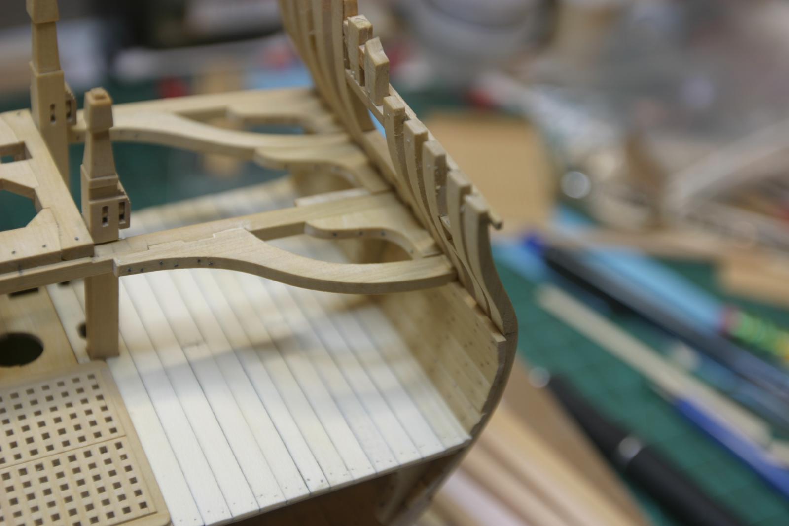
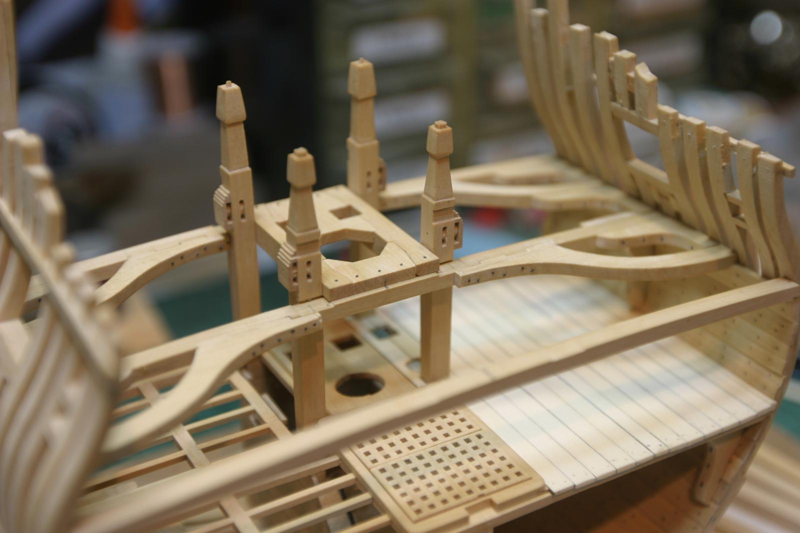
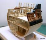
Very little progress...other obligations. Upper deck beams and knees in place. Next up the carlings and ledges. The hanging knees on the aft beam hang out from the planking. I'm not sure whether to put them on. Any thoughts? Notice on the first pic. there is a turned pillar supporting the center of the foreward beam, This was taken from a cross section in a much earlier chapter. It sits atop the king plank (segment) and required notching the frame for the lower deck gratings. I'm not sure this is correct...just how I interpreted the earlier illustration. Maury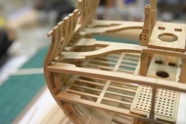
- 324 replies
-
- 11
-

-
Alexandru, Insects can not stand orange oil. It's avail. as an insect repellant or furniture polish. It's non-toxic to humans and pets. Wipe a little orange oil on the wood and they'll leave you alone. Maury
-
Steve, the 1/16 bit is WAY TOO BIG.. That would be 3" at 1:48 scale. Maury
-
Echo by Maury S - FINISHED - Cross-Section
Maury S replied to Maury S's topic in - Build logs for subjects built 1751 - 1800
Look at Greg's pictures for inspiration! I keep a picture pinned up in my workspace all the time. Maury -
Echo by Maury S - FINISHED - Cross-Section
Maury S replied to Maury S's topic in - Build logs for subjects built 1751 - 1800
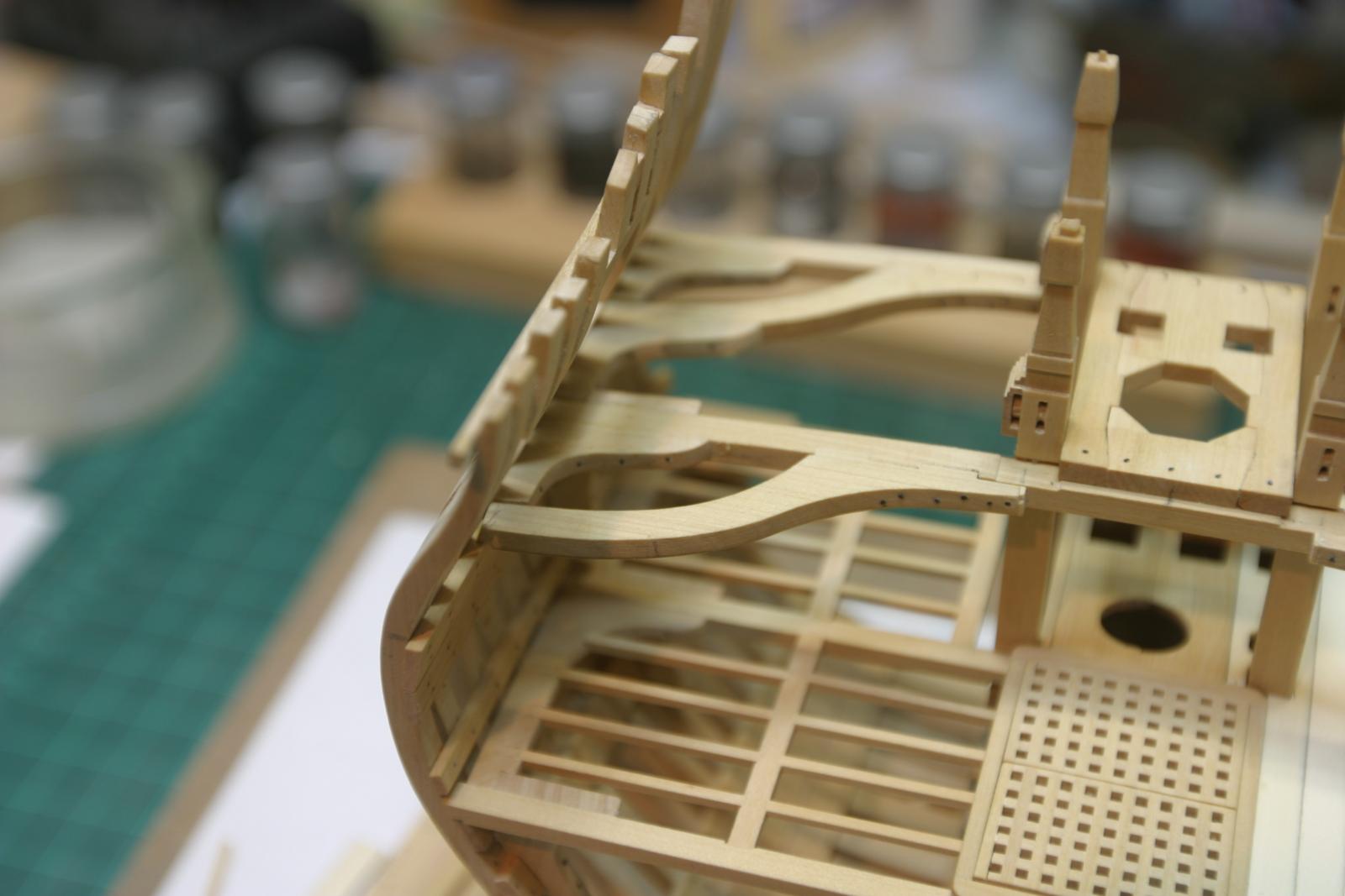
Adding pieces to the deck. As the hanging knees on the mid-beam are now in, next items were the forward beam arms. After they were dry, the lodging knees were added and lastly the forward deck beam installed. Next come the remaining lodging and hanging knees. Maury

-
Echo by Maury S - FINISHED - Cross-Section
Maury S replied to Maury S's topic in - Build logs for subjects built 1751 - 1800
Thanks for the comments. The fishing line is black monofilament under the brand Amnesia. I think it's the 20 lb test. It measures at about .017" or about .81" diameter at 1:48 scale. I bought it on Amazon. Be careful, it comes in all sorts of glow in the dark colors. Maury -
Echo by Maury S - FINISHED - Cross-Section
Maury S replied to Maury S's topic in - Build logs for subjects built 1751 - 1800
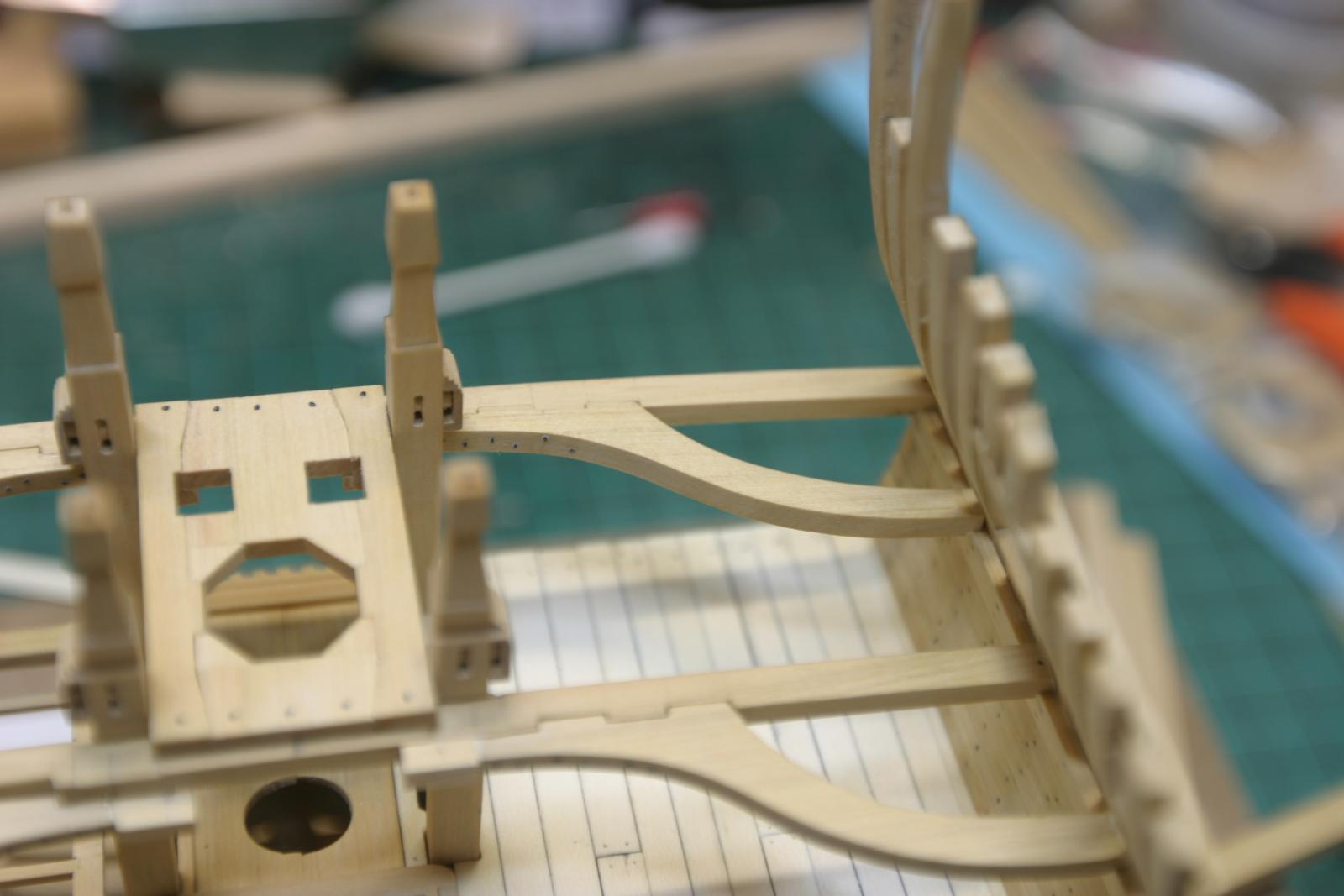
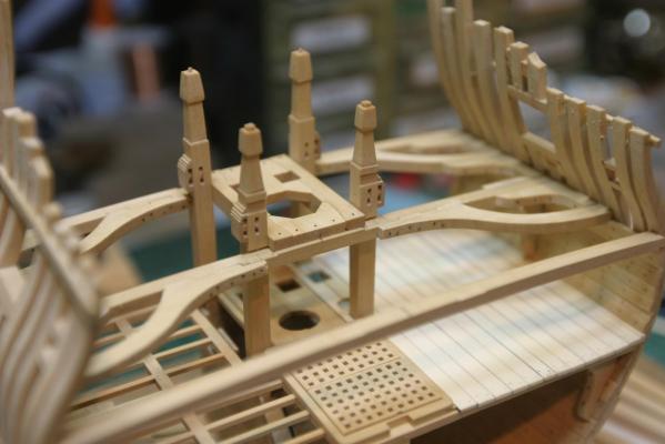
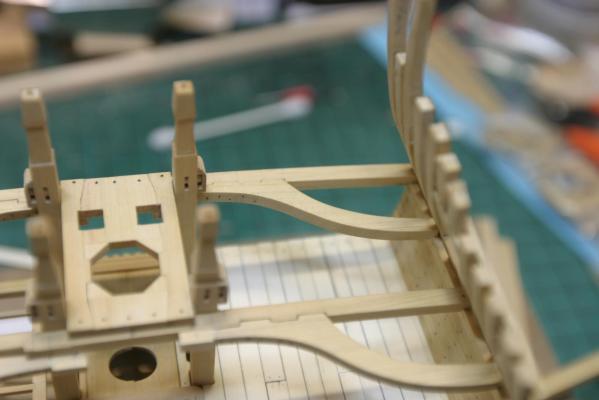
The template for the holes on the upper deck has been put on and off a dozen times to line up the pump cases, etc. Now it's time for the upper deck beam arms and other details. I thought I had mis-measured the length of the beam arms, so I put an extension on the end (visible on the end of the arm near the partners carling). No need. The original measurements allowed for the thickness of the bitts on the aft beam and the carlings on the mid beams. They got sanded off. The order of the pieces is probably important from an ease of access issue. I installed the arms, then went to work on the lodging knees between the beams and arms on the middle beam, then I'll fit the hanging knees and then move to the fore and aft beams. The port side will be decked, so I may skip some of the ledges on that side. All the arms and knees have simulated bolt heads, made with black monofilament line (thanks Ed Tosti). Same on the upper mast carlings and partners, though I'm not sure they would have been that visible. Artistic license. Maury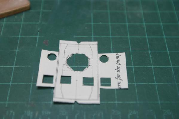
-
Echo by Maury S - FINISHED - Cross-Section
Maury S replied to Maury S's topic in - Build logs for subjects built 1751 - 1800
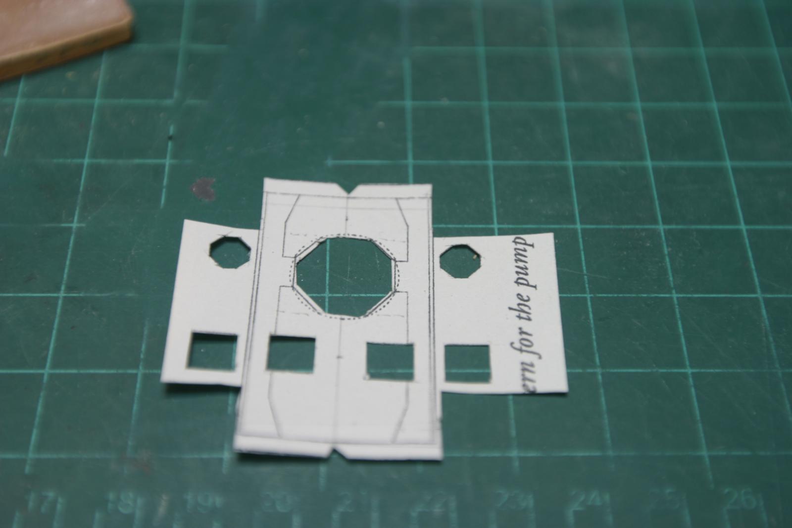
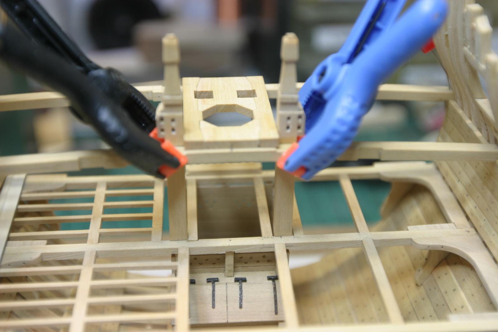
In order to line up the pump cases, elm tree pumps and mast partners the upper deck beams need to be aligned. As I read it, the aft edge of the center beams (upper and lower) must align vertically. Slight variation for the fore and aft beams is tolerable. I used a machinist square to line up the center beam and pin it in place. Once that and the aft beam are situated, you can finish the carlings and partners. Use a card template copy of the scaled partner layout with holes cut out for the cases, elm tree, mast and the bitts. Then the cases can be inserted at the correct angles and positions. This is where I found the problem with the well walls. Once that's done, the lower deck planking can be started. Getting a good fit of the cases through the planking is tricky and best achieved by making a card template and adjusting to make everything fit (Octagonal hole for the elm tree being the most difficult). I went through three card templates and two pieces of wood before I was happy. Maury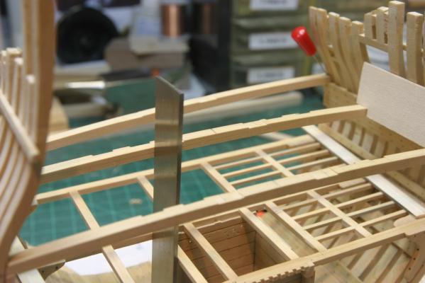

-
Echo by Maury S - FINISHED - Cross-Section
Maury S replied to Maury S's topic in - Build logs for subjects built 1751 - 1800
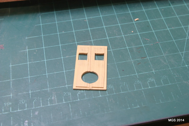
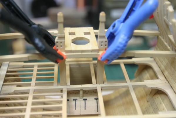
Upper Deck Mast carlings and partners: A challenge but not hard. I squared up a piece to 11" sided and used the table saw to cut out the flat parts, a chisel to cut the angled parts, and I inserted 6" square battens on the lower edge for the ledges/supports. The partners were a bit more of a challenge with the octagonal hole for the mast. Per Greg's technique in TFFM III, I cut little 45 degree corner pieces and glued them in place to created the octagon. It took a few times to get the little pieces to match the size of the other edges. Picture's a bit blurry. Next is lining up the upper deck center beam. Maury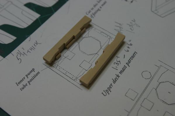
- 324 replies
-
- 10
-
-
Echo by Maury S - FINISHED - Cross-Section
Maury S replied to Maury S's topic in - Build logs for subjects built 1751 - 1800
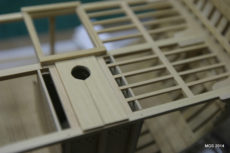
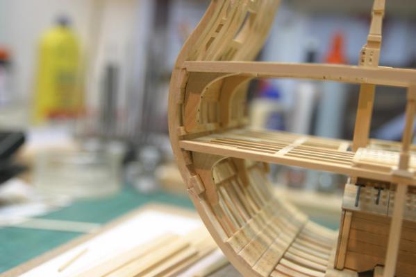
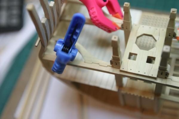
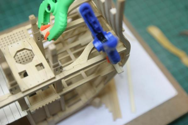
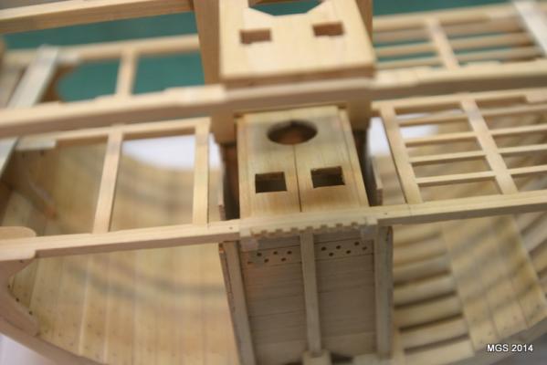
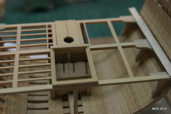
The lower deck partners were modified a bit. A thin strip was added to the inner edge of each piece to push the partners out over the carlings. Under side shows the let-in so they fit between the beams and carlings. There is a minor re-do on the carlings. There needs to be room for the pump cases etc to fit so a second set of carlings is needed outboard of the existing ones. Because the ledges aligned well, I chose to remove the notched carling and relocate it to the outboard position and re-size the ledges. New carlings were then added to the notches left from the removed pieces. Also note...My well is either way too narrow, or the plans needed on-site revisions. The pump cases pass thru the decks, between the set of carlings and intersect the top walls of the well rather than pass through to the limber channel. I can't replace the well at this stage, so I cut out parts of the side walls to allow the cases to at least look like they are going into the well. The inside of the well will not be visible so it's a mistake few will notice. DIfferences can be seen between pics two and three. Maury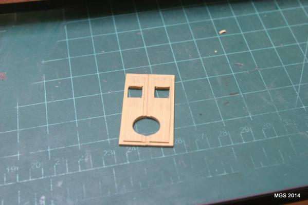

-
Echo by Maury S - FINISHED - Cross-Section
Maury S replied to Maury S's topic in - Build logs for subjects built 1751 - 1800
Grant, Back when I did a lot of (furniture) woodworking, the standard way of cutting a dado involved stacking blades and maybe chippers between. Just be sure the blades are the same diameter and hole same diameter. Maury -
Echo by Maury S - FINISHED - Cross-Section
Maury S replied to Maury S's topic in - Build logs for subjects built 1751 - 1800
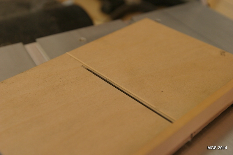
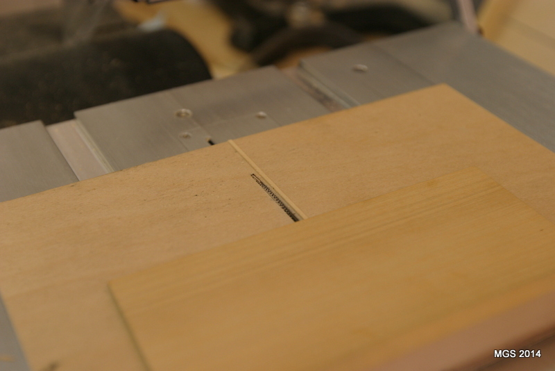
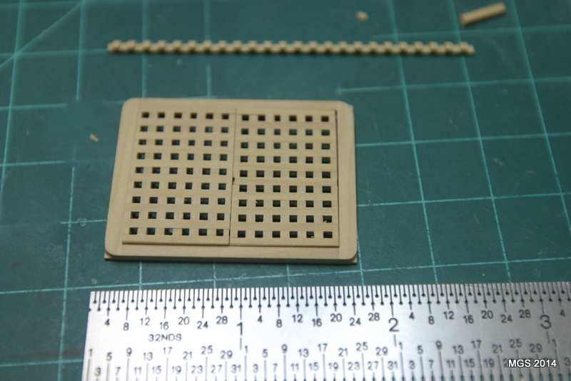
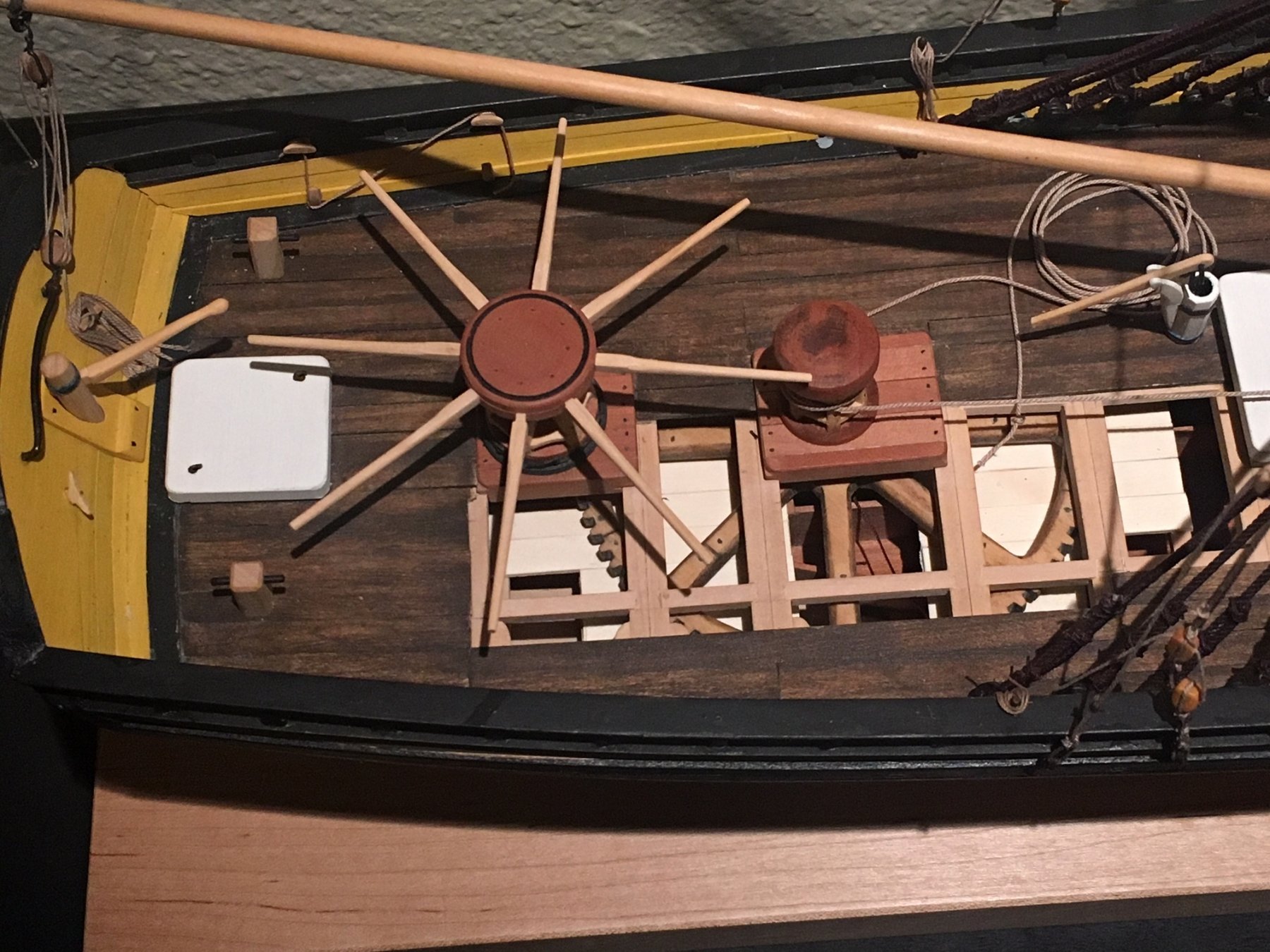
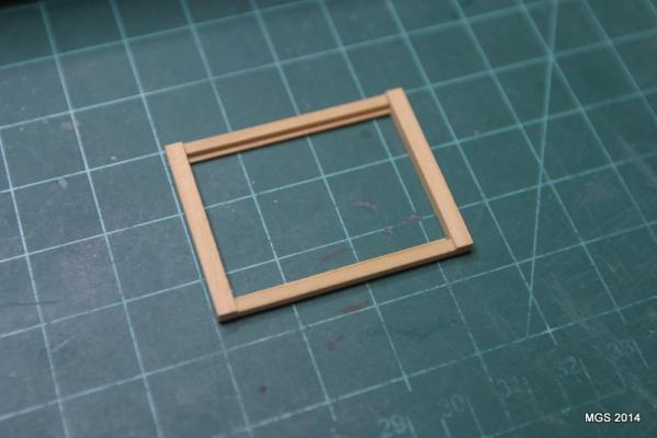
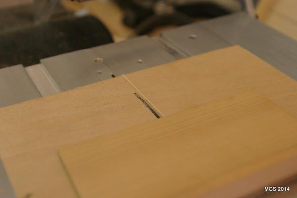
Back at work on the section. Next step is the partners. I drilled a 19" (+ / _) hole in a piece and then cut it in half. Later I added a thin strip to the cut edges to widen it over the carlings...and let down the underside edges 1" on the sides and ends to fit over the beams and carlings. Edges are softened. The coamings and head ledges to the lower deck hatches are 6" wide and 4" thick. There are 2" x 2" rebates in the coamings (not the ledges) for the grating. The corner joints are a simple over-lap. Since the deck planks are 2" thick, I followed David's lead from TFFM. Cut a corner out of a piece of 2" thick scrap and use that as a platform to notch the corners with a chisel, then cut down on a 45 degree angle to the platform (leaving a square section on the lower edge). The 45 degree angles were then rounded off with a 220 grit sanding stick. Time to talk about the gratings. I did not have a slitting blade near the required thickness of about 2 3/4" (.057" at scale) so I put two blades together with a .05" thick paper spacer to attain the required thickness. I first tried the method Greg described in Vol. 3 of TFFM (moving a scrap 2 x the thickness of the cut, adjusting the fence and repeating. They did not come out even so I built a jig. This time I put a square piece of thin plywood against the fence and over the blade and raised the blade well thru the ply. The fence was then loosened and a piece of batten material two times the thickness of the two-blade cut was inserted between the ply and fence and the fence re-tightened. The blade was then lowered, batten removed and ply re-set against the fence. This created an offset the desired width of the gratings. I then raised the blade to cut about 1/2 the thickness of the batten and ran the ply over the blade creating a channel or dado the thickness of the batten. Batten then inserted and glued in the dado creating a fence in the jig. Hardwood sliders cut to fit the channels in the saw table, jig flipped over so the new fence was on the top side, blade raised thru the open slot in the jig, sliders set in the table and glued to the ply. Jig completed. Picture attached. Blade set to the proper height thru the jig and a piece of 1/16" box wood material run cross grain over the blade, repositioned over the fence and repeated until I had enough material. That was then sliced into the notched pieces for the gratings. More later. Maury


-
Emma's a great way to transition to POF. Rabbet is cut before frames are attached while you can work on it laying flat. Very sharp chisels or xacto knives. Very light cuts repeatedly. The angle of the rabbet changes so take your time. Maury
-
Undo what is not right. You will be happier in the end. Maury
-
Ed, What a beauty! Great lines. The soaking and re-clamping is a new one for me. Maury
-
Strip storage
Maury S replied to capt-j's topic in Building, Framing, Planking and plating a ships hull and deck
My experience with storing strips vertically is they take on a bend. Find a way to lay them flat. Maury -
18' Cutter by Maury S - Scale 1:48 - SMALL
Maury S replied to Maury S's topic in - Build logs for subjects built 1751 - 1800
Druxey, Thanks so much. That's a great suggestion. The first plank resting on the transom is in and it came out well.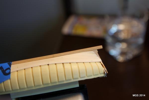
-
18' Cutter by Maury S - Scale 1:48 - SMALL
Maury S replied to Maury S's topic in - Build logs for subjects built 1751 - 1800
Druxey, Thanks. I took it off the plug to re-glue the transom and was shocked at how much glue seepage there was. I apply glue very sparingly with the tip of a pin, but I've been assured that it can be sanded and scraped off. The shell was very stable at that point. Once I get a plank attached to the transom, it will be quite strong. All that time spiling on previous models is paying off. Maury -
18' Cutter by Maury S - Scale 1:48 - SMALL
Maury S replied to Maury S's topic in - Build logs for subjects built 1751 - 1800
Thanks for all the likes and comments. The underside has some glue seepage, but I'm reasonably sure I can get it off. Fore end of the fourth strake is in place. Aft end fits over the transom, so this first plank is going to be a challenge getting it around the sternpost without leaving a gap. A bit of beveling and a notch should make it work. So far, all planks seem even from side to side, top and fore-aft. Pleasing run from all views. Maury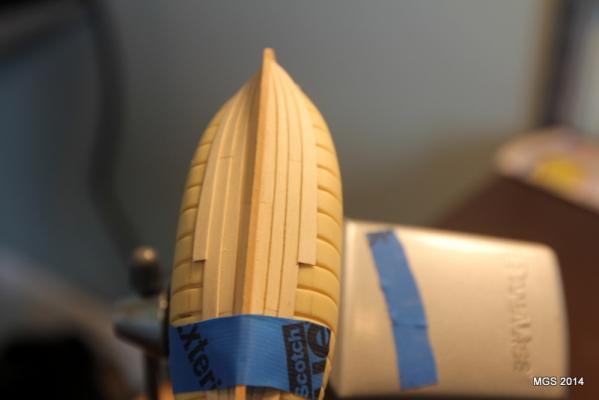
-
18' Cutter by Maury S - Scale 1:48 - SMALL
Maury S replied to Maury S's topic in - Build logs for subjects built 1751 - 1800
Thanks Druxey. The overlaps are sanded. I clean off the glue that seeps out as I attach the plank, but I have no idea how the underside looks. David, the boat will be left natural. First full strakes above the garboard are installed. Some slight trimming needed on the butt joint of the last plank (visible on the left) and after smoothing it will still be under the overlap of the next plank. I'm using the scored lines in the starboard side of the plug as a planking guide, and using tick strips I mark the same distance from the keel on the port side at each rib. So far, the spiling of the planks has matched one side to the other. Maury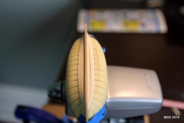
-
18' Cutter by Maury S - Scale 1:48 - SMALL
Maury S replied to Maury S's topic in - Build logs for subjects built 1751 - 1800
Bob, Good eye. David pointed out in the instructions that almost all of the ribs were left on the plug when he lifted the shell off the plug. He therefore recommends that the planks be laid without ribs and then go back and form up the ribs separately and install them inside the finished shell. Maury -
18' Cutter by Maury S - Scale 1:48 - SMALL
Maury S replied to Maury S's topic in - Build logs for subjects built 1751 - 1800
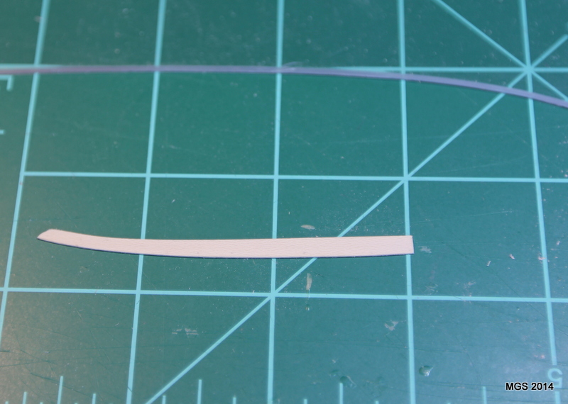
Pic. of the ends of the first planks above the garboard. You can barely see the scores on the plug that guide me to the run of the planks. Both planks are the same width at the ends so there is some camera-angle distortion. My over-lap is much smaller than 1/32". I wonder if that will present a problem when I take it off the plug (not enough gluing surface?) Any thoughts? Maury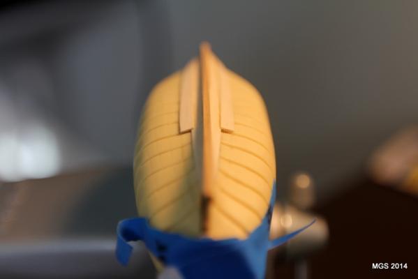
-
18' Cutter by Maury S - Scale 1:48 - SMALL
Maury S replied to Maury S's topic in - Build logs for subjects built 1751 - 1800
Dave, There is about 1/32" over-size to account for the overr-lap if the garboard plank. Whem I fit it on, I had to sand off about 1/64" to line it up to the scores on the plug. As for the exposition, I'm just following the instructions David and Greg put out. Masters, both. It's a good thing that isopropyl disolves titebond glue! Maury -
18' Cutter by Maury S - Scale 1:48 - SMALL
Maury S replied to Maury S's topic in - Build logs for subjects built 1751 - 1800
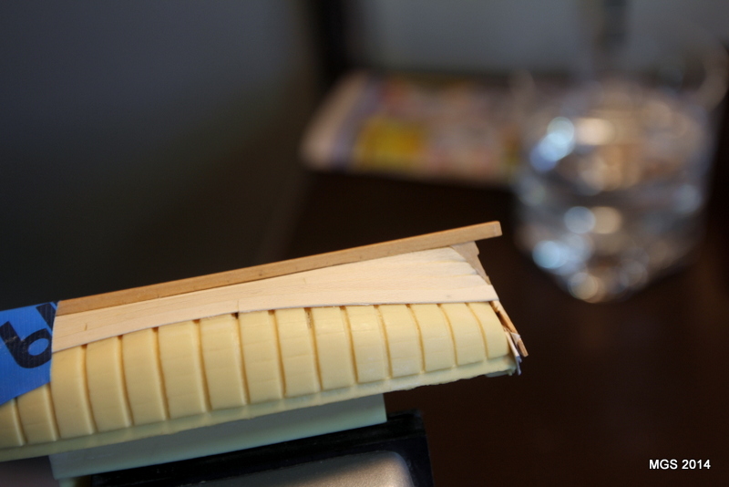
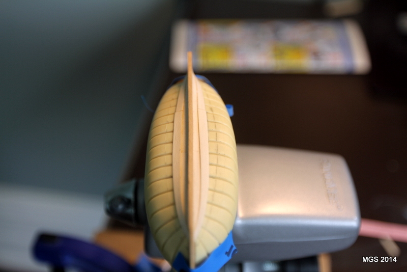
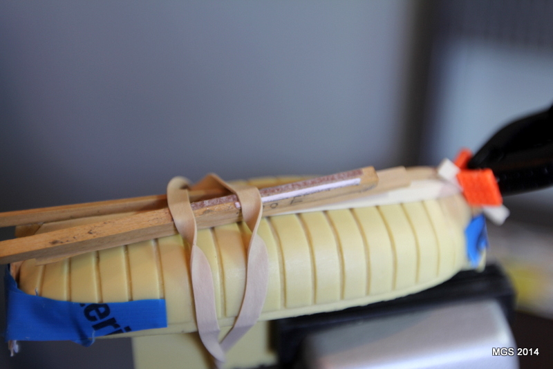
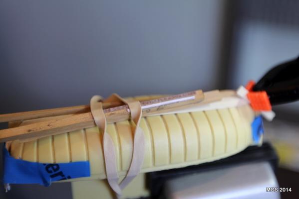
Now on to the first strake above the garboard (mounted upside-down). This is where the edge of the garboard gets sanded a bit and the fore end of the plank gets a rolling bevel to 45 degrees. Not as hard as I thought, but I think I'll do the rolling bevel on the next side before I glue it in place. I don't have a full compliment of clamps so scrap planks and rubber bands will do. Maury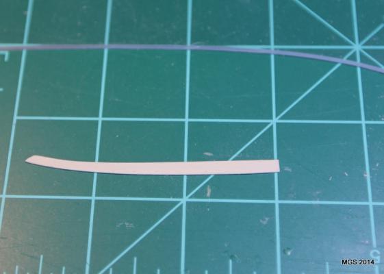
-
18' Cutter by Maury S - Scale 1:48 - SMALL
Maury S replied to Maury S's topic in - Build logs for subjects built 1751 - 1800
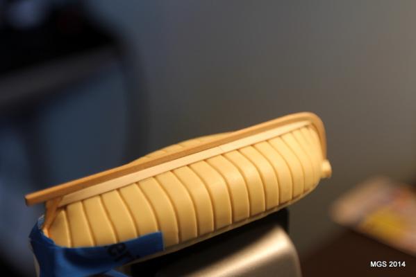
Pics of the garboard planks installed. Butt joint barely visible ate frame 8. Maury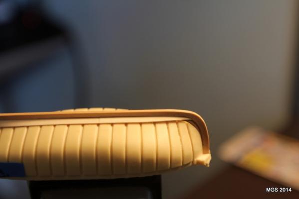
- 43 replies
-
- 11
-