Maury S
-
Posts
1,490 -
Joined
-
Last visited
Content Type
Profiles
Forums
Gallery
Events
Everything posted by Maury S
-
 Thanks for the comments. Jay, I think pre-beveling opens up another can of worms. I actually used a very well honed chisel on the edges of the bulkheads near the bow. If you cut the bulkheads to the plans carefully, sand to the outside edge of the lines (if you have a spindle and disk sander) and just sand away by hand once installed, I think it would work out best. It's rigid enough to hold up to the sanding. Maury
 -
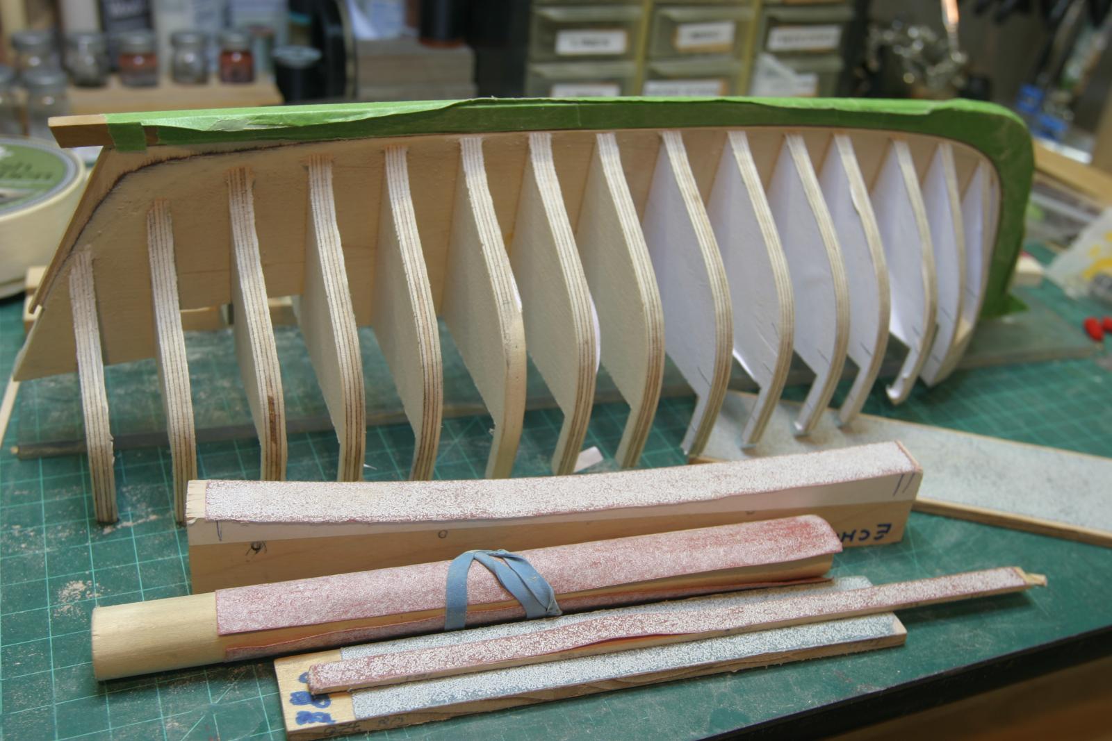
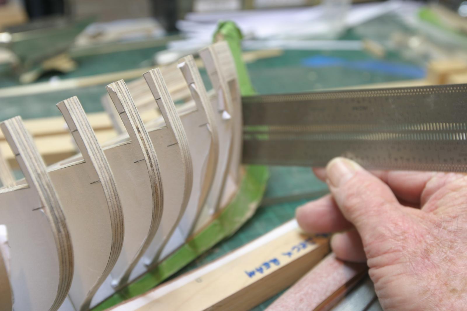
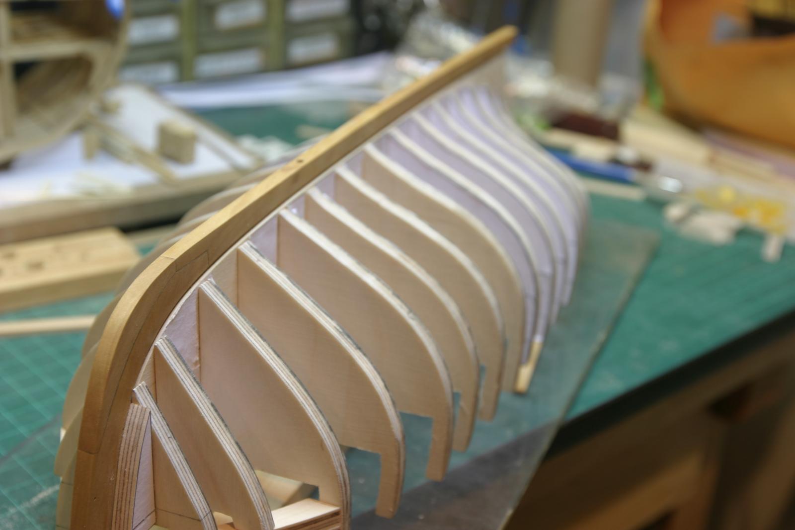
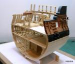
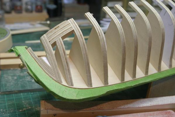
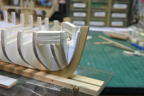
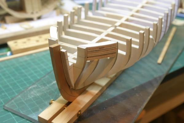
Thanks for all the like and comments. If you see a problem or have a warning, PLEASE point it out. They are easier to fix earlier in the process. Rough fairing in process. Boy, does this make a lot of sawdust! I taped up the stem and keel so I wouldn't damage them with all the sanding to be done. In addition to checking the fairing with a thin batten, I checked the width of each bulkhead from the spine at the reference lines. I added some vertical reference lines to the aft most bulkhead and checked there as well. The sides can be fair, but still not the same from port to starboard (I made that mistake on my Emma C. Berry a few years back). Several minor sanding adjustments and one bulkhead that needed building up by about 1/64". Some 1/32" scrap bass is glued on the edge and will be sanded down to the proper level. More checking along the keel then on to the next step. Maury


-
Thanks Chuck. It's all about learning techniques that work. I've never edge bent a plank before, but since I'm working from your Cheerful plans, and have seen how well (and easy) you make it look, this will be my first. Great discussion!!! Maury
- 1,051 replies
-
- 4
-

-
- cheerful
- Syren Ship Model Company
- (and 1 more)
-
You're creating a real challenge for us with the moldings; but what's life with a few challenges? Maury
- 1,051 replies
-
- 4
-
-
- cheerful
- Syren Ship Model Company
- (and 1 more)
-
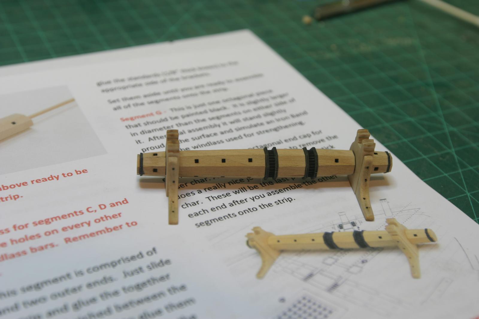
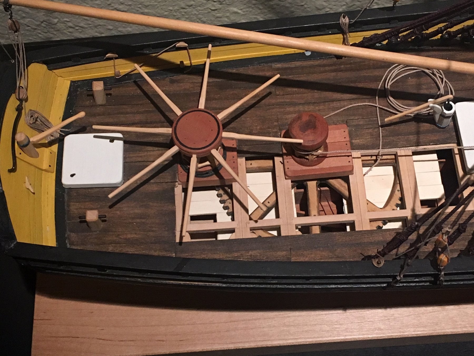
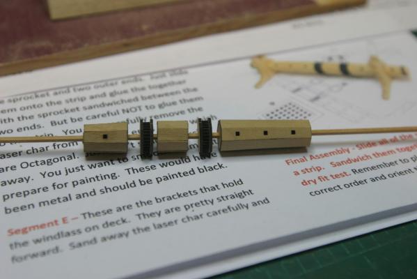
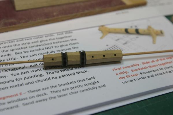
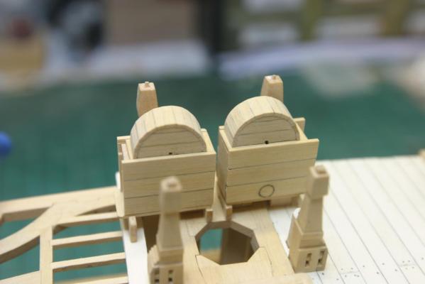
Thanks for all the likes and comments. The windlass is finished. Only one goof. Can you spot it? The holes for the handles on the two outer pieces are out of alignment with those on the center piece. When you assemble each barrel, it would be good to start each one with either the solid or holed face lined up with a square side of the axle and keep it constant. Since the two outer pieces are the same, I don't think I have to take it apart. Warning...some of the pieces are VERY SMALL. It's a great addition to the Cutter Cheerful plans. Maury

-
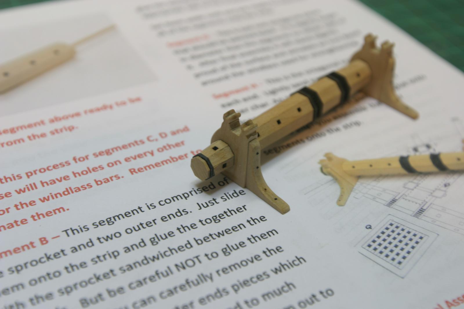
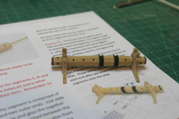
While waiting on more glue to dry, I put a few more pieces of the windlass together. I learned a little trick (after too many tries). Getting the octagonal piece to stay square with the axle while gluing on the faces is awkward. By holding the octagonal piece on the axle against the already assembled gear section on the axle, there is a solid, square base for gluing. Just don't let the two sections get glued together just yet. Hard to explain, but it worked well on the section D I just assembled. I love this little kit. Chuck is a genius. Maury
-
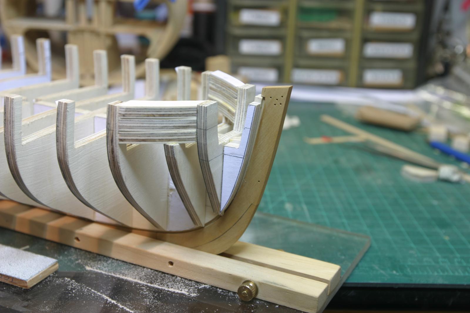
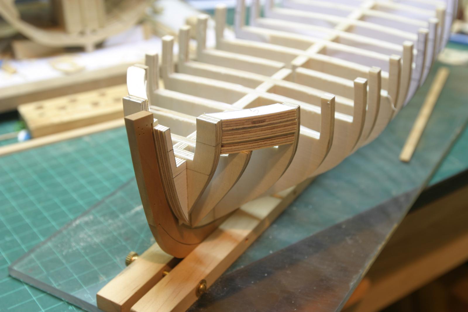
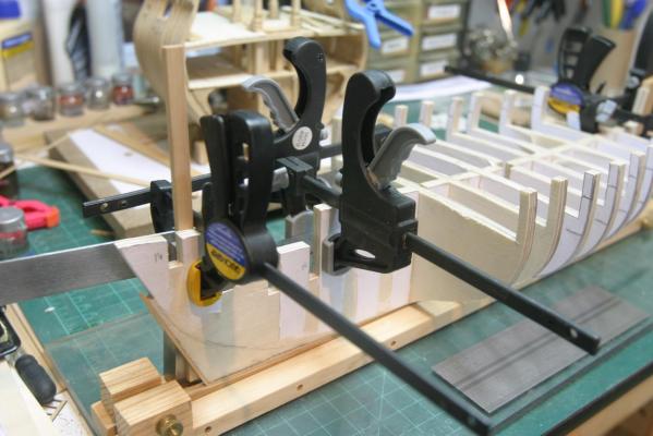
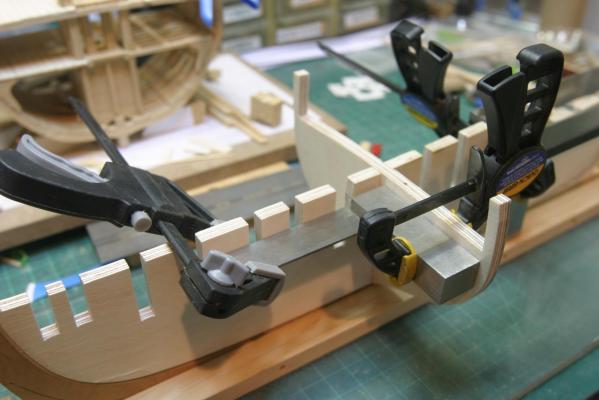
More installation of bulkheads ( clamping with small machinist squares). The only questionable thing so far is the issue of the bow fillers. Chuck's instructions call for special attention to lining up the reference lines. Doing so resulted in the fillers being about 1/8" + lower than the matching tops of the spine and bulkheads. (you can make it out on the 2nd and fourth pictures). I re-checked the reference lines and they are square from the bulkhead "M". I can always fill-in at the top and re-draw ref. lines on the fillers. Chuck's photos show the fillers tops flush with the spine tops. Port fillers were sanded to shape and glued in place. Now to fairing. The plan is to use an 80 grit sanding block and go at it for a few days. There is a lot to remove. As Chuck points out, this is a critical stage!!! Maury

-
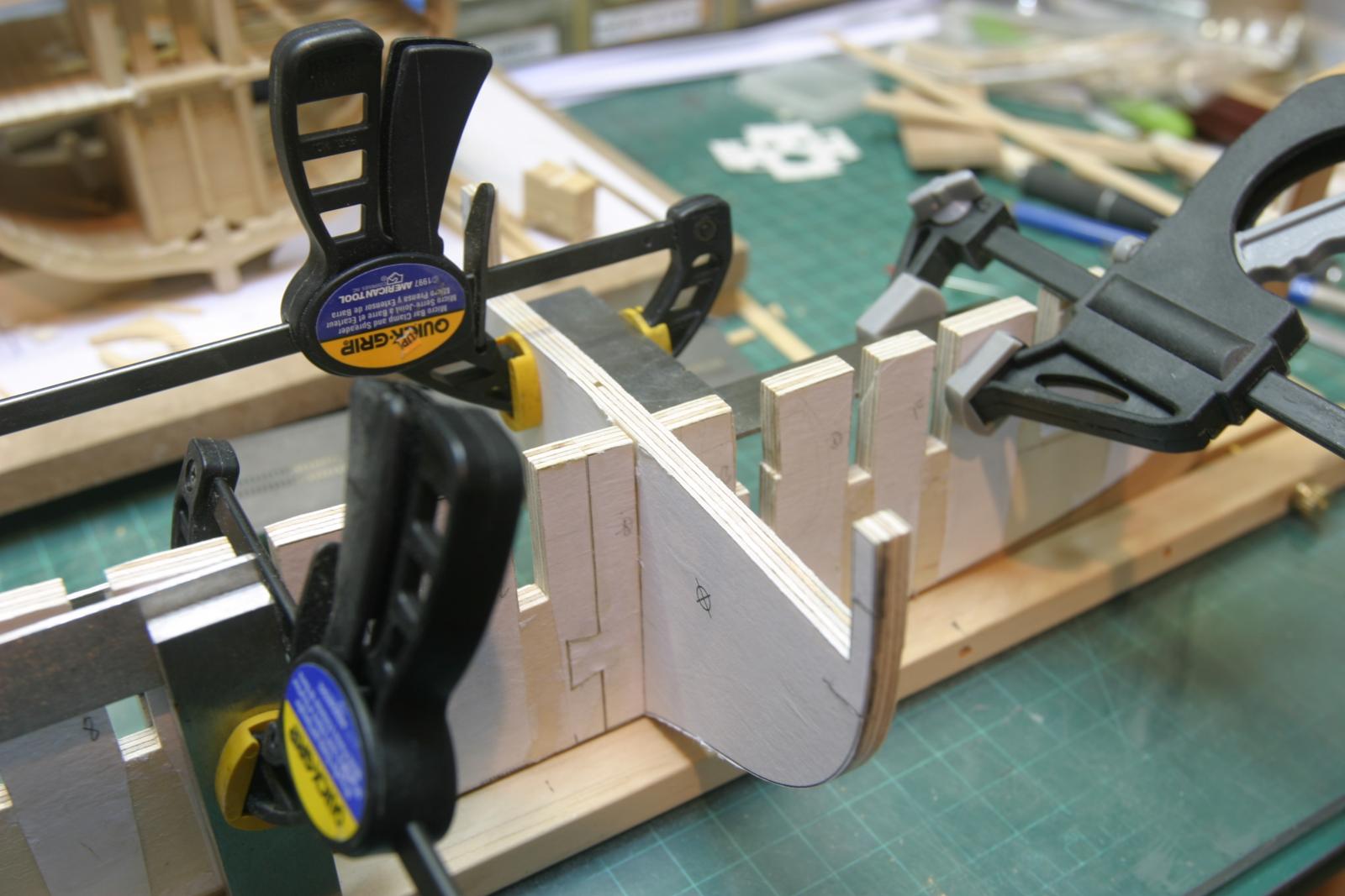
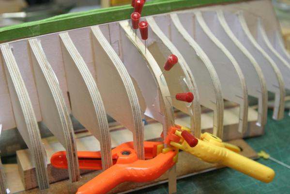
I drilled the mounting holes using my mill to make sure they were centered and plumb, then tapped them. I then started installing the bulkheads to the spine. I clamped the spine plumb in a make-shift jig and then glued and inserted the dead-flat bulkhead (pattern facing aft) and clamped it square to the spine. After about 20 minutes of drying, I can move on to the next bulkhead, working away from dead-flat. Maury

-
As I finished the poly on the stem and keel, I realized I had not made provision for mounting. It might have been easier to drill mounting holes before gluing the keel to the spine. I'll square up the unit in the drill press and drill and tap for 4-32 bolts. Box wood is hard enough to hold mounting bolts in a tapped hole. Maury
-
Blackening brass problem
Maury S replied to Maury S's topic in Metal Work, Soldering and Metal Fittings
I've ordered the Brass Black. Kurt, thanks for the instructions for use! Maury -
The rabbbet is easy...just make sure to align it in the center of the spine. I had to wait for more timber for the keel and stem parts. I bought three 5/16 (rough finish) pieces of box wood from Lumberyard. It has a lot of grain, a few knots and was bowed and warped. Nothing like the quality I was used to from Hobby Mill. I stacked and weighted the pieces and after ten days, they flattened out a lot. The stem pieces and keel were thicknessed to 7/32" (.219"), cut on the scroll saw and finished with the oscillating sander, disk sander and sanding sticks. A lot of trial and error when you cut them like this. Since the stem and keel are .22" vs the .24" of the spine, I used a piece of card stock (manilla folder material) under the pieces while gluing to the spine. Clamped while setting. I'll take off the patterns, finish with wipe-on poly and be ready to set the bulkheads. Maury
-
Blackening brass problem
Maury S replied to Maury S's topic in Metal Work, Soldering and Metal Fittings
Thanks all! Maury -
Echo by Maury S - FINISHED - Cross-Section
Maury S replied to Maury S's topic in - Build logs for subjects built 1751 - 1800
Thanks Toni, The pieces were totally covered with a "silver" soft solder before I filed it down. That's most likely the problem. Maury -
I've run into a problem blackening some brass parts. I've done it hundreds of times before without a problem. Sand or file the pieces, pickle in vinegar for an hour and rinse. Soak in Acetone for an hour and rinse. Put in 1:5 dilute Blacken-It for an hour. There is a reaction, but the result is a pinkish color, not black. Does Blacken-It go bad? Mine's 5 year's old. I understand it's not sold any more. I used Apple Cider vinegar the first time and thought it might be that, but a repeat of the process with white vinegar produced the same result. Any thoughts? Maury
-
Echo by Maury S - FINISHED - Cross-Section
Maury S replied to Maury S's topic in - Build logs for subjects built 1751 - 1800
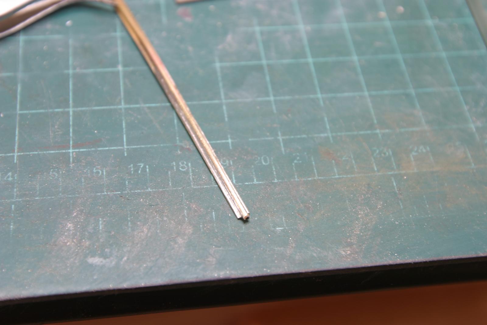
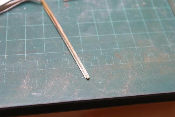
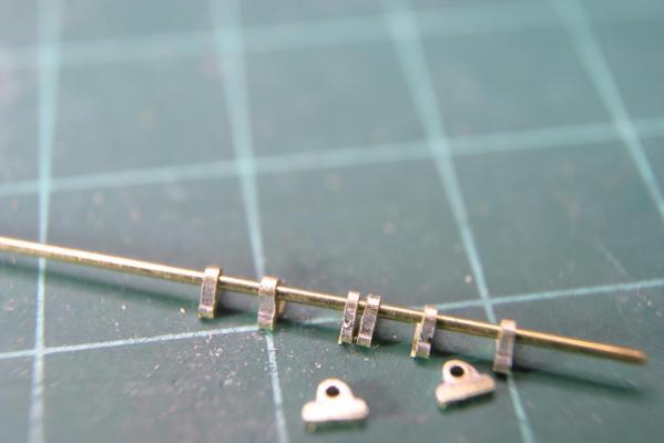
I had some time to do some metal work. The rhodings are bearings that support the chain pump axle. You can't install the cisterns 'til you line up the axle between the bitts and the top of the cistern. I started by lining up the 1/16" tubing on top of a 1/32 x 1/8 strip of brass. I silver-soldered the pieces together for about 2". I then used regular solder to fill in the gap and create a single piece. The regular solder is much softer and melts quickly (way too much solder went on). I had a lot of filing to do to bring it into shape. Once I was happy with the cross-section shape, I cut off 1/32" slices to make the rhodings. A 1/32" brass rod (axle) fits into the tubing. A really good learning exercise with soldering. I blackened them (1:8 dilute Blacken-It), but they came out pinkish, not black. Maybe the apple cider vinegar I used to prep them. Anyone have this experience? I'll re-try with white vinegar and see what happens. Maury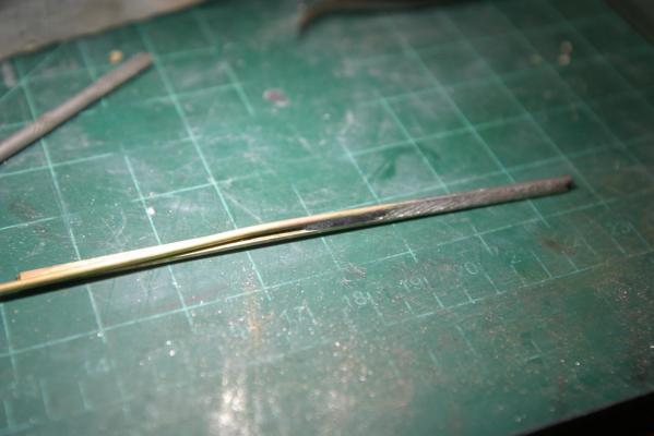
-
18' Cutter by Maury S - Scale 1:48 - SMALL
Maury S replied to Maury S's topic in - Build logs for subjects built 1751 - 1800
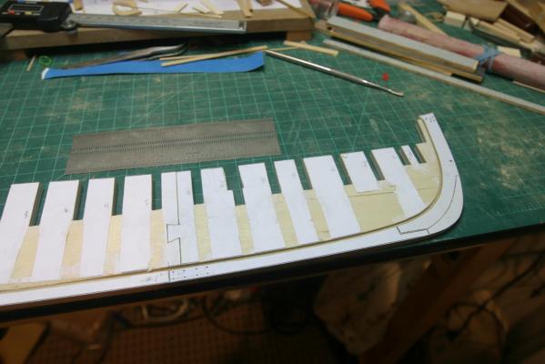
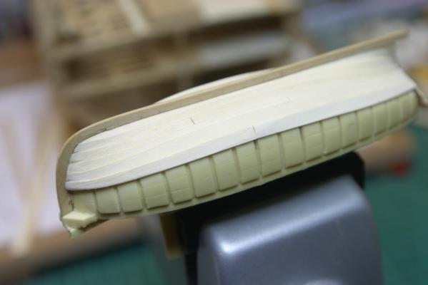
The small cutter is a fill-in project when I can't work on the Echo Section or now Chuck's Cheerful. Every once in a while I'll add another strake of planking. The dip in the last strake will disappear when the next plank goes on. The next few planks will be critical. Maury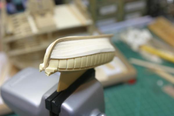

- 43 replies
-
- 15
-
-
Echo by Maury S - FINISHED - Cross-Section
Maury S replied to Maury S's topic in - Build logs for subjects built 1751 - 1800
The axle construction is in the next installment, so I'm finishing off the wood details on the pumps, stanchions etc. Nothing will be glued to the model since lining up the axles thru the rhodings, etc. will be critical. I don't want to get ahead of David and Greg because it will inevitably lead to me taking something apart. Maury -
Echo by Maury S - FINISHED - Cross-Section
Maury S replied to Maury S's topic in - Build logs for subjects built 1751 - 1800
Wow, I'm approaching the 2 year anniversary for this build. I bought the last package of 1/32" rod from Ace. Plunger is temporarily installed (not blackened yet) and the support band around the top of the pump tube painted and installed (Black acid-free paper painted with iron black). It will only be visible from about 1/8" below the out-flow tubing. I'm thinking about the rhodings (bearings) for the chain pump. The 1/32" rod fits inside a 1/16" tubing. If I solder the tubing against a sheet of brass flat material, I could cut off appropriately sized segments for the 5 pieces needed. Worth a try. They would have to be installed on the axle system as it is being assembled / soldered and then attached to the cistern top, bitts and end support. Maury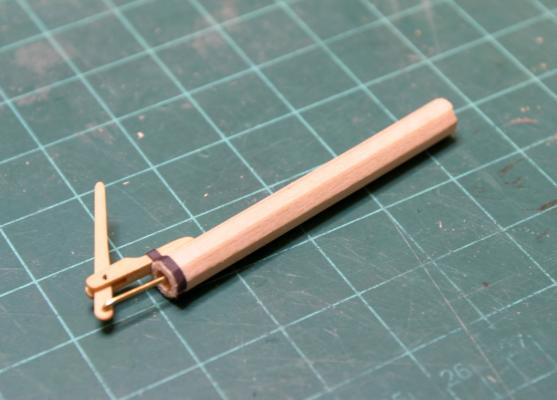
-
Echo by Maury S - FINISHED - Cross-Section
Maury S replied to Maury S's topic in - Build logs for subjects built 1751 - 1800
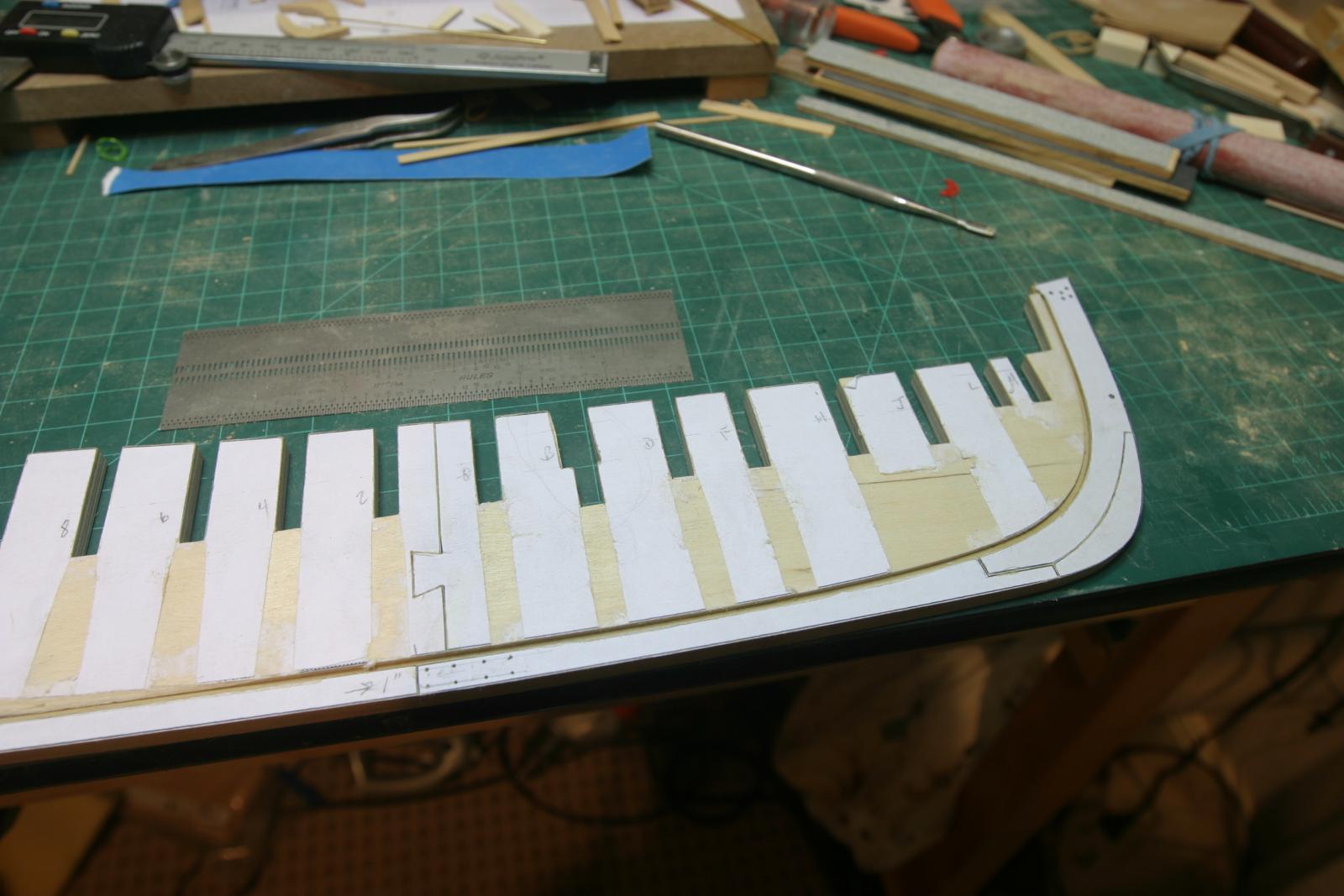
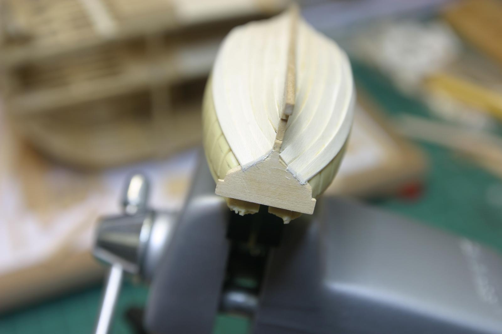
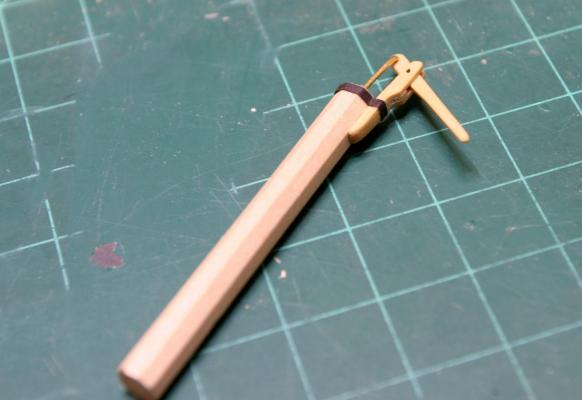
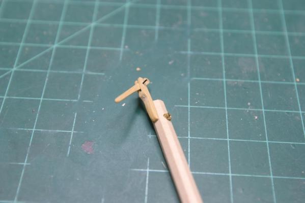
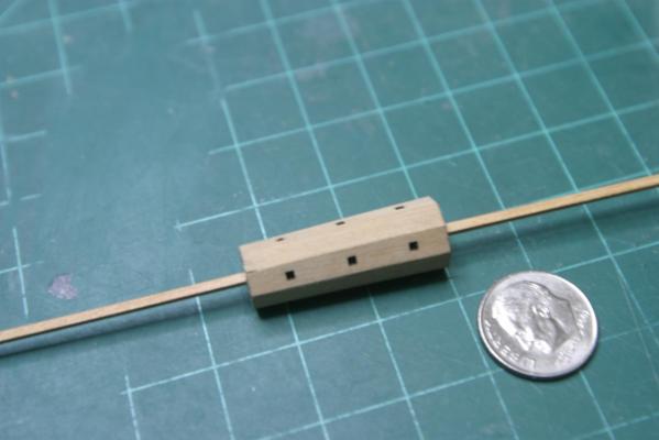
Thanks for all the "likes". Work on the brake pump and handle continues. The only measurement given is the handle. Everything else interpreted from the drawings. The handle is 3' 6" long, 3" at it's widest part and 1 1/2" thick (.03125") . I under-sized it to .03" thick so it would not bind (see next sentence). The bracket for the handle is three sandwiched .03125: pieces, roughly shaped, glued together and then finish-sanded. The center piece is cut short, resulting in a slot for the handle. The out-flow tube is brass, yet to be darkened. The plunger rod is yet to be installed. Each little section is a project into itself. The axle and handle for the chain pump is going to be a challenge. Keeping everything along the axis with several 90 degree bends means soldering pieces, not just bending. As I read the plans, it runs above the edge of the hatch. That must mean it was removed when not in use so it would not interfere with moving material in and out through the hatch. Any thoughts? Maury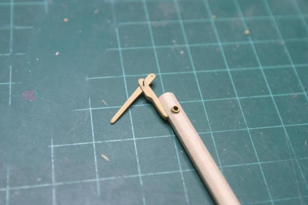
- 324 replies
-
- 10
-
-
Echo by Maury S - FINISHED - Cross-Section
Maury S replied to Maury S's topic in - Build logs for subjects built 1751 - 1800
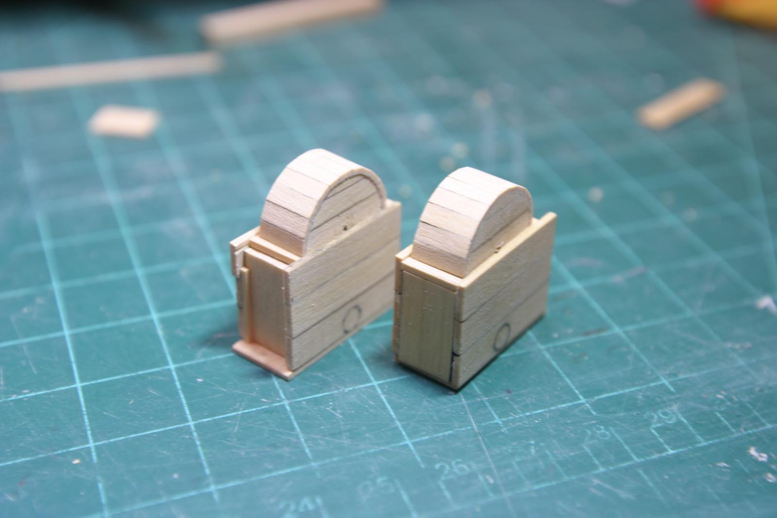
Next stage is the (octagonal) brake pumps and (Square) chain pumps and cisterns. I'm not going to detail the inside of the pumps since they do not fit all the way down to the keel. They will be just solid square pieces. Rather than build a frame for the cistern(s) I cut a solid block for the inside and used a piece of 5/8" dowel cut to 5/16" thick (a full half dowel) for the pump covers. The base is 1/16" and the planking material is 1/32" of assorted widths. The legs are 1/16". I'm not going to install a dale for draining the cisterns, so I made the outer ends with a solid piece that would be removed when the dale was put to use. I don't have any 1/32" brass rods for the axle so I'll have to wait to work of the rhodings (bearing-like fixtures that hold the axles in place). I suspect I'll use brass tubing and sheet material for those. That will be metal working so I'll fiddle with the brake pumps for now. Maury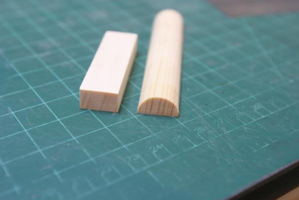

- 324 replies
-
- 13
-
-
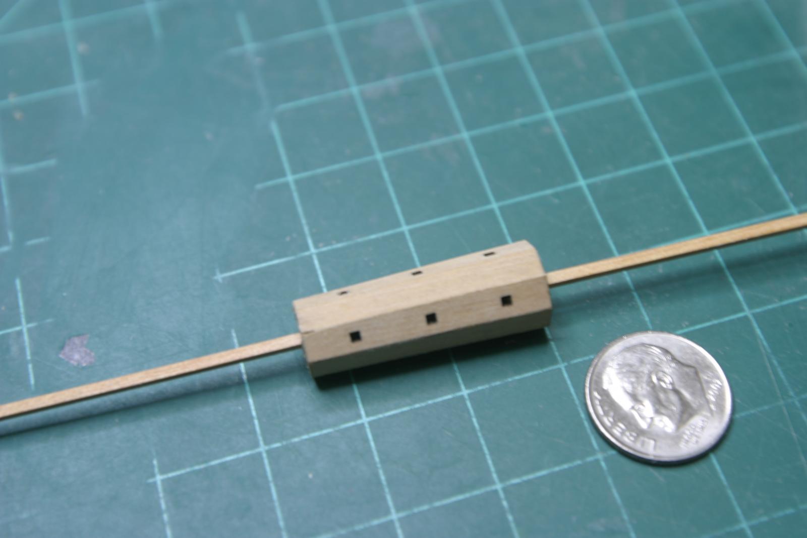
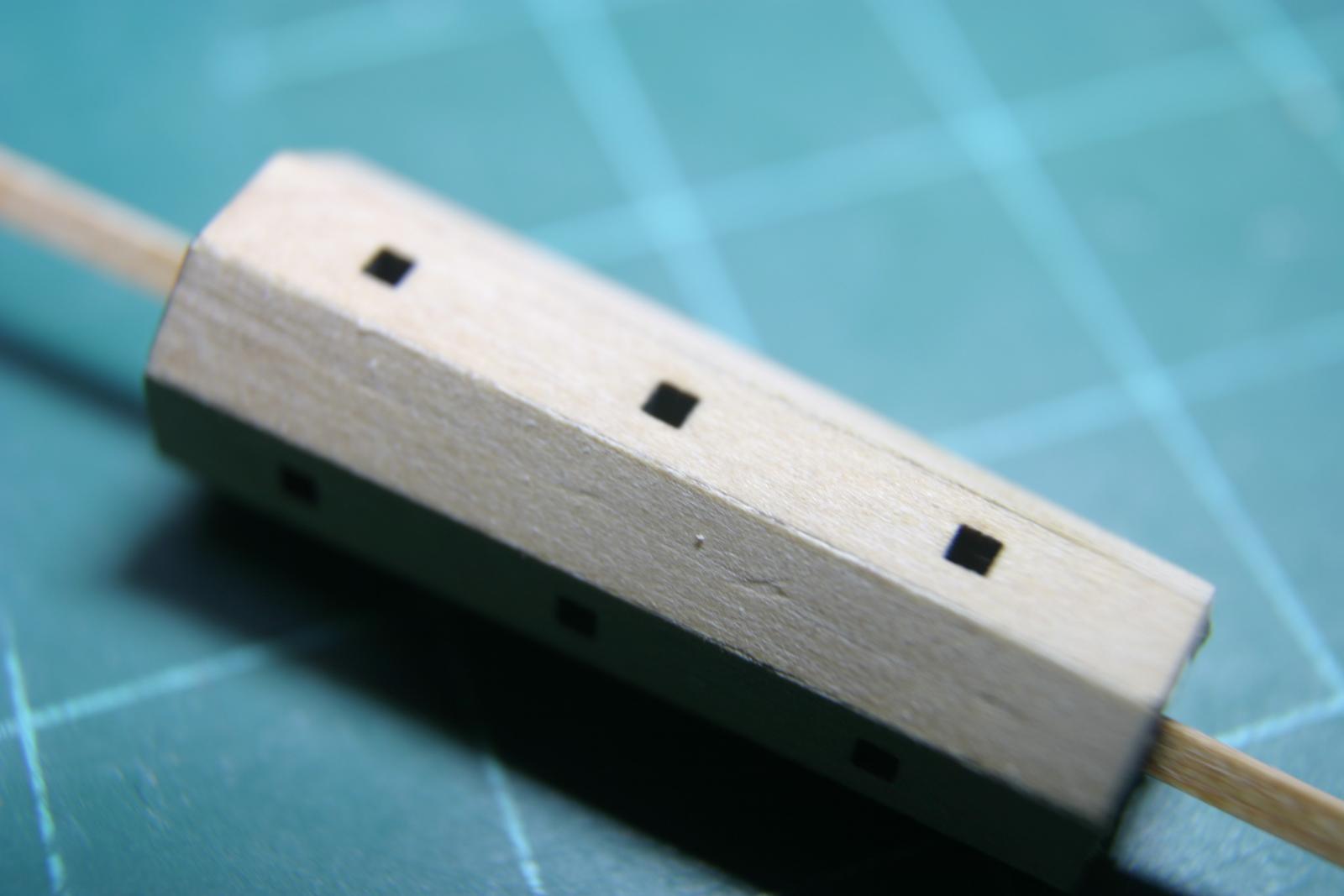
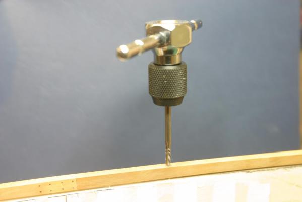
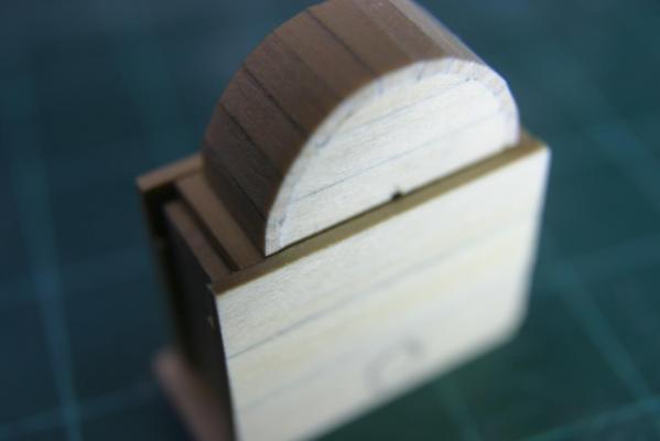
Barrel part C. I took the first attempt apart (that's why they invented isopropyl), and sanded just a hair more off each long edge using the 22.5 degree bevel jig. They fit nicely this time. Snug to the octagonal supports. Lining up the ends of the first side perfectly on the octagon pieces insures everything else coming together. The smaller barrel parts will be a different challenge. Going back to work on the Echo Section http://modelshipworld.com/index.php/topic/513-echo-cross-section-by-maury/ soon, so the windlass is probably on hold for a while. Maury

-
Ed, So you paint soldiers in your spare time? Love the process lessons. Maury
-
Echo by Maury S - FINISHED - Cross-Section
Maury S replied to Maury S's topic in - Build logs for subjects built 1751 - 1800
Greg and David should have the next installment in a few days. Then back to my main project (Echo Section). Looking forward. So much to learn and this is a great way to do it. Maury